lntrodutin9 the ne~ - elpakco.com · lntrodutin9 the ne~ -pony l'in -qua\ified b1 c.ontelh...
TRANSCRIPT


() .. -) -
lntrodutin9 the ne~ -PONY l'IN qua\ified b1 C.ontelh 14searlh for use
in the interlonneltion industr1 espelia\\1 for mu\ti\a1er ballepane\s
----------press-fit into p\ated-thru ho\e, siz.e.o'3o+.oo'3
ac.t.epts \ead siz.es
.01(/'0 to .o?.-5" sq. post
'\\\\
/unique "c." shaped t.ross sec.lion tai\ p\u9s into a standard .o'3o" +.oo'3 diameter 'PT\-\ to form a 9as ti9ht t.onnec.tion
.o<,1--" head diameter for ?.-mm spac.in9 app\ilations
.05i"barb a\\ows pin to mate ~ith a\\ readi\1 avai\ab\e p\astic. wafert> in the standard Dl-P, '5l'P and header st1\es

Quick Find! Table of Contents I
~ DIP Sockets Series Product Description Page Page 5 Specs General Data & Technical Specifications 4
Mfg. Facilities Capabilities 2-3
Series 10 Open Frame DIP Sockets 5
Series 10C Open Frame DIP Sockets with Capacitors 6 Series 11 Glass Epoxy DIP Sockets 7
Break-Away Series 11A DIP Adaptor Boards 8 Strips
·----·--··------~-·-SeriesTO Transistor Sockets 8
Page 9-10
;4111"'•· Series 12 Break-Away Strip Sockets 9
Series 12 Break-Away Adaptors 10 I ________ ----- ...
Series12CW Cut-Away Extender Strip Sockets 13
Series 13 Closed Frame DIP Sockets 14 Series 14 Disposable Aluminum Carrier Sockets 15
Series 15 PGA Sockets 16
Series 15 PGAAdaptors 17 Series 15A Interstitial PGA Sockets 18
Series 15/15A PGA Footprints 19-22
Series 18 Adaptor Sockets 25 Series 19 Crystal Oscillator Sockets 26
Series SD Shrink-DIP Sockets 26 Series20 Elevated Sockets 27
.050x .050 Pinto Pin Strips & Headers 28
Series SMC Decoupling Capacitor Sockets 29 0 SeriesZZ Zig Zag Sockets 30
Series RA Right Angle LED Sockets 31
Series MS Mini Shunts 34
Zig Zag Sockets Series PH .025" Square Post Pin Header 35 Page 30 r--~
Series38 108-Pin Male & Female Connectors 37
Terminals Stamped Terminals 38
Terminals Crimped Terminals 39
Connectors Shorting Plugs 40
Solder Terminals Swager Terminals Swager 40 Page 84-102 ~-,--~ Connectors Teflon Press Mount Style Jacks 41
'~:~~:' M55155 Insulated Feed-thruTerminals 42-44 '~J :,?'~. Terminals One Piece Pin Receptacles 45
JL_ c!. ,.
Terminals Loose Piece Terminals 46-63
Terminals Printed Circuit Pins 64-81 Terminals Wire Wrap Terminals 82
Loose Piece r--·- -·· . ___ ...... Series PMP Ordering Information & Technical Specifications 84 Receptacles ! .,._\ A1,'
Series PMP Solder Terminals · 85-103 Page 46-63 ~ - ~ _ , -
~ ~;t ... , Series MP Mini Pins 104-105
~>t Contacts Loose Contacts 106-112 4. '
Index Part Number Index 113-114
©Elpakco, Inc., 1998
ELPAKCO, INC. 2 Carl Thompson Road, Westford, MA 01886, Tel: 978-392-0400, Fax: 978-392-6814
1
4
General Data
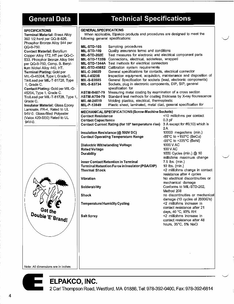
SPECIFICATIONS Terminal Material: Brass Alloy 360 1/2 hard per QQ-B-626. Phosphor Bronze Alloy 544 per QQ-B-750. Contact Material: Beryllium Copper Alloy 172, HT per QQ-C-533. Phosphor Bronze Alloy 544 per QQ-B-750, Comp. B. Beryllium Nickel Alloy 440, HT. Terminal Plating: Gold per MIL-G-45204, Type I, Grade C. Tin/Lead per MIL-T-81728, Type 1, Grade C.
Contact Plating: Gold per MIL-G-45204, Type 1, Grade C. Tin/Lead per MIL-T-81728, Type 1 Grade C. Insulator Material: Glass Epoxy Laminate, FR-4, Rated to UL 94V-0. Glass-filled Polyester (Valox 420-SE0) Rated to UL 94V-0.
Get the Double'E'B randl
Note: All dimensions are in inches
Technical Specifications
GENERAL SPECIFICATIONS When applicable, Elpakco products and procedures are designed to meet the
following general specifications:
MIL-STD-105 MIL-STD-109 MIL-STD-202E MIL-STD-1130B MIL-STD-1344A MIL-STD-45662 MIL-C-39029 MIL-I-45208 MIL-S-83505 MIL-S-83734
ASTM-B487-79 ASTM-A754-79 MIL-M-24519 MIL-P-13949
Sampling procedures Quality assurance terms and conditions Test measures for electronic and electrical component parts Connections, electrical, solderless, wrapped Test methods for electrical connectors Calibration system requirements General specifications for contacts, electrical connector Inspection equipment, acquistion, maintenance and disposition of General Specification for sockets {lead, electronic components) Sockets, plug in electronic components, DIP, SIP, general specification for Measuring metal coating by examination of a cross section Standard test methods for coating thickness by X-ray flourescence Molding plastics, electrical, thermoplastic Plastic sheet, laminated, metal clad, general specification for
MECHANICAL SPECIFICATIONS (Screw-Machine Sockets) Contact Resistance <10 milliohms per contact Contact Capacitance 0.3 pF Contact Current Rating (for 10° temperature rise) 3 A except for #6(10) which is
2A Insulation Resistance(@ 500V DC) Contact Operating Temperature Range
Dielectric Withstanding Voltage Rated Voltage Durability
Inner Contact Retention in Terminal Terminal Retention Force in Insulator (PGA/DIP) Thermal Shock
Vibration
Solderability
Shock
Temperature/Humidity Cycling
Salt Spray
10000 megaohms (min.) -55°C to +150°C (BeCu) -55°C to +225°C (BeNi) 1000V AC 100VAC 1000 Cycles (min.)@ 10 milliohms maximum change 7.5 lbs. (min.) 10 lbs. (min.) <2 milliohms change in contact resistance after 4 cycles No electrical discontinuities or mechanical damage Conforms to MIL-STD-202, Method 208 no discontinuities or mechanical damage (10 cycles of 2000G's) <2 milliohms increase in contact resistance after 21 days, 40 °C, 93% RH <2 milliohms increase in contact resistance after 48 hours, 35°C, 5% NaCi
ELPAKCO, INC. 2 Carl Thompson Road, Westford, MA 01886, Tel: 978-392-0400, Fax: 978-392-6814

('
r
Series 10
DESCRIPTION The Open Frame design allows
for maximum cooling and inspection, All insulators are end-to-end and side-to-side stackable, Series 10 is available in sizes 6 to 64. The precision screw-machine outer shell and the four-finger BeCu inner contact allow for easy IC insertion.
SPECIFICATIONS Insulator Material: Glass-filled Polyester Thickness: .100"to .112" Flammability Rating: UL94V-O Operating Temperature: -55°C to +125°C Shell Material: Brass Contact Material: BeCu Shell Plating: Tin over Nickel and Gold over Nickel Contact Plating: Tin over Nickel and Gold over Nickel Lead Size Range: .015" to .022"
DIMENSIONS
No.of 'A' 'B' ·c· Pins 6 .300 8 .400 10 .500 14 .700 16 .800 .300 .400 18 .900 20 1.00 22 1.10 24 1.20 28 1.40 22 1.10 .400 .500 24 1.20 24 1.20 28 1.40 32 1.60 36 1.80 .600 .700 40 2.00 48 2.40 50 2.50 52 2.60 .900 1.00 64 3.20
Note: All dimensions are in inches
Open Frame DIP Sockets
[IQ]- 3 -18 - 04
Series~·
10 - Open Frame DIP
-T -~
1 OE - Slim Line .050" Thick DIP Spacing 3- .300" 4- .400" 6- .600"
Contact Plating G-10µ" Gold T-150µ" Tin
Shell Plating G -10µ" Gold T-150µ"Tin
Terminal Style 9 - .900" Total Number of Pins
6-64 (Choose from selections below)
T B
_L
-08
A
0 0 00000000 001
C
00000000--1
.193
-:t~ .025 jff' 03 - .500 SQUARE~ ___J_
-02/-03
t .132
j _.1 25
t -132 Series 1 OE Only
-07
f .095
.095
t -451
Series 1 OE Only -8 Press-fit in .030 ±.003 -9 Press-fit in .038 ±.002 -477
ELPAKCO, INC. 2 Carl Thompson Road, Westford, MA 01886, Tel: 978-392-0400, Fax: 978-392-6814
5
6
Series 10C
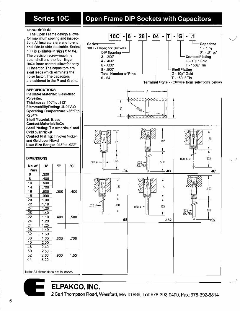
DESCRIPTION The Open Frame design allows
for maximum cooling and inspection. All insulators are end-to-end and side-to-side stackable. Series 1 DC is available in sizes 6 to 64. The precision screw-machine outer shell and the four-finger BeCu inner contact allow for easy IC insertion. The capacitors are axial leads which eliminate the noise factor. The capacitors are soldered to the P and G pins.
SPECIFICATIONS Insulator Material: Glass-filled Polyester. Thickness: .100"to .112" Flammability Rating: UL 94 V-0 Operating Temperature: -76°Fto +284°F Shell Material: Brass Contact Material: BeCu Shell Plating: Tin over Nickel and Gold over Nickel Contact Plating: Tin over Nickel and Gold over Nickel Lead Size Range: .015" to .022"
DIMENSIONS
No.of 'A' 'B' ·c· Pins
6 .300 8 .400 10 .500 14 .700 16 .800 .300 .400 18 .900 20 1.00 22 uo 24 1.20 28 1.40 22 1.10 .400 .500 24 1.20 24 1.20 28 1.40 32 1.60 36 1.80 .600 .700 40 2.00 48 2.40 50 2.50 52 2.60 .900 1.00 64 3.20
Note: All dimensions are in inches
Open Frame DIP Sockets with Capacitors
11oc1Js -Series-----J1
10C - Capacitor Sockets DIP Spacing 3 - .300" 4- .400" 6 - .600" 9 - .900" Total Number of Pins 6 - 64
Capacitor 1 - .1 pf 01 - .01 pf
28 - 04 - T -L-Q}_ Contact Plating G -10µ" Gold T-150µ" Tin
Shell Plating G -10µ" Gold T-150µ" Tin
Terminal Style - (Choose from selections below
A
T 0000000000001
B
l_
-04
-08
C
000000 _l
.193
--f .025t .500 SQUARE I _l
-03
-132
ELPAKCO, INC. 2 Carl Thompson Road, Westford, MA 01886, Tel: 978-392-0400, Fax: 978-392-6814

(',
_r--.
Series 11
DESCRIPTION The Glass Epoxy DIP sockets
are available in custom configurations. There are alternate types of Glass Epoxy material that are available. The tum-around time is very quick! Series 11 is available in sizes 6 to 64. The precision screw-machine outer shell and the four-finger BeCu inner contact allow for easy IC insertion.
SPECIFICATIONS Insulator Material: Glass Epoxy Laminate Thickness: .062" Flammability Rating: UL 94V-O Operating Temperature: -76°F to +284°F Shell Material: Brass Contact Material: BeCu Shell Plating: Tin over Nickel and Gold over Nickel Contact Plating: Tin over Nickel and Gold over Nickel Lead Size Range: .015" to .022"
DIMENSIONS
No.of 'A' 'B' 'C' Pins 6 .300 8 .400 10 .500 14 .700 16 .800 .300 .400 18 .900 20 1.00 22 1.10 24 1.20 28 1.40 22 1.10 .400 .500 24 1.20 24 1.20 28 1.40 32 1.60 36 1.80 .600 .700 40 2.00 48 2.40 50 2.50 52 2.60 .900 1.00 64 3.20
Note: All dimensions are in inches
Glass Epoxy DIP Sockets
Series
~- 3 - 18 - 04 • T -~
11 - Glass Epoxy DIP Contact Plating G -10µ" Gold T-150µ" Tin
DIP Spacing 3 - .300"
Shell Plating G-10µ" Gold T-150µ" Tin 4- .400"
6- .600" 9 - .900"
Terminal Style Total Number of Pins (Choose from selections below) 6-64
A
T 000000000000!
8 C
J_ ~~~~oo"'-',,!Jo ~
-04
-08 POLOPIN
.020 ~
.125
I J
-132
~~~ ~ .310
lli.170 ,125
-07
f .095
.095
t
-451
-83 -98 Press-fit .038 ± .002 -477
ELPAKCO, INC. 2 Carl Thompson Road, Westford, MA 01886, Tel: 978-392-0400, Fax: 978-392-6814
7

8
Series 11A
DESCRIPTION This series 11A is available in
custom configurations. The bifurcated design allows for large diameter components.
SPECIFICATIONS Insulator Material: Glass Epoxy Laminate Flammability Rating: UL 94V-O Operating Temperature: -65°C to +125°C Terminal Material: PhBr Terminal Plating: Tin over Nickel and Gold over Nickel
Note: All dimensions are in inches
Series TO
DESCRIPTION Series TO is available in a
number of custom configurations. The Transistor sockets also have a very low profile.
SPECIFICATIONS Insulator Material: Glass-filled Polyester Flammability Rating: UL 94V-O Operating Temperature: -65C to +125C Shell Material: Brass Contact Material: BeCu Shell Plating: Tin over Nickel and Gold over Nickel Contact Plating: Tin over Nickel and Gold over Nickel Lead Size Range: .015" to .022" diameters
Note: All dimensions are in inches
DIP Adaptor Boards
Series----~ 11A- DIP Adaptor Boards
1
DIP Spacing--~ 3- .300" 4-.400" 6- .600" 9 - .900"
.075
Terminal Plating G - 1 0µ'' Gold T-150µ"Tin
Terminal Style 10- Stamped
Total Number of Terminals 6-64
Tr+-=-==-=-==-==-= -r A 'A" + .150 .062
__L ============ _J ·~mnmm·+ Transistor Sockets
Series---~ TO - Transistor Sockets
•.' ''<{'' ·~·., lti. -B- ,!li -L Contact Plating G-10µ" Gold
Total Number of Pins T-150µ"Tin
'-----Shell Plating G-10µ"Gold T-150µ"Tin
3 4 8 10 8-1
.230 8-1 Pin
j?__ .200 3-Pin
4-Pin
~ --lfot._ 8-Pin
10-Pin
ELPAKCO, INC. 2 Carl Thompson Road, Westford, MA 01886, Tel: 978-392-0400, Fax: 978-392-6814

Series 12
DESCRIPTION Series 12 allows the user to
custom design the Break-away strip to whatever size is desired. Single row strips are available in sizes up to 36 positions. These strips are end-to-end and side-toside stackable. This series can be customized in a Dual (2 x 40) or Single (1 x 36} row format.
SPECIFICATIONS Insulator Material: Glass-filled Polyester Flammability Rating: UL94V-O Operating Temperature: -55°C to +125°C Shell Material: Brass Contact Material: BeCu Shell Plating: Tin over Nickel and Gold over Nickel Contact Plating: Tin over Nickel and Gold over Nickel Lead Size Range: .015" to .022" diameters
BREAK·
AWAY
INTO ANY
REQUIRED
LENGTH!
Note: All dimensions are in inches
Break-Away Strips (SINGLE & DUAL Row)
12 - Standard (.100" Thk.) 12D- Dual Row (.112" Thk) 12E - .050" Thick, Single 12F - .050" Thick, Dual Row
Total Number of Pins 2- 80
-04 -T-, Contact Plating G -10µ" Gold T-150µ" Tin
Terminal Plating G-10µ" Gold T -150µ" Tin
Terminal Style (Choose from selections below)
Single Row (1 x 36) Dual Row (2 x 40)
f-- .100 x NO. OF PINS __j 100 ~ .100 X NO. OF PINS --j I PER ROW I _J_ I PER ROW I _J_ l0IOIO!OIOJQ!QIQIQ]Q]Q]OIO!OI 00000000000000 200 ~ I I~ ' 0000000 000000 ·
-100 --i r- .1 oo-l ~ f --r
I .193
-04
-:+360 .025 ~ 03 - .500 SQUAREW~ l
-02/-03 -07
.095 .OJD t
-08 -132 Series 12E/12F Only -451
.082
t
-83 Press-fit in .030 ± .003 -99 Press-fit in .038 :!: .002 -477
ELPAKCO, INC. 2 Carl Thompson Road, Westford, MA 01886, Tel: 978-392-0400, Fax: 978-392-6814
9

10
Series 12
DESCRIPTION Series 12 allows the user to
custom design the Break-away strip to whatever size is desired. Single row strips are available in sizes up to 36 positions. These strips are end-to-end and side-toside stackable. This series can be customized in a Dual (2 x 40) or Single (1 x 36) row format.
SPECIFICATIONS Insulator Material: Glass-filled Polyester Flammability Rating: UL94V-O Operating Temperature: -55°C to +125°C Terminal Material: Brass Terminal Plating: Tin over Nickel and Gold over Nickel
BREAK
AWAY
INTO ANY
REQUIRED
LENGTH!
Note: All dimensions are in inches
Break-Away Adaptors(SINGLE & DUAL Row)
~-36
Series__J 12 - Standard (.100" Thk.) 12D - Dual Row (.112" Thk.) 12E - .050" Thick, Single 12F - .050" Thick, Dual Row Terminal Style
(Choose from selections below)
Total Number of Pins 2 - 80
Single Row (1 x 36) Dual Row (2 x 40)
j- .100 X NO. or PINS -i I PER ROW I __l I- .100 X NO. OF PINS --J .100
I PER ROW l__l 10IOIO!O[QIOIOIO!OIOIQIOIOIQI
.100--l I-- ' ffi818Bl818B!8Bl818Bl81 -200
.100-l I- f
.018 f .156
_j_ -09
.025
.155
! t
.018 t .156
l -290
-505
.018 • t .156
__L -11
.018 •
.072 f
.018 f
t
1I .050 I 1: t
f .125
t -335
t .125
~ r1 .100
t f
.125
i -585
.018 f t .125
.050
.072 t
~ _J_.210
.050 I l t
f .125
.018 • t -210
.018 f f .125
.050
.072 •
t t
_J_,385
Tl ,100
t f
.125 .018 • t
-385
.018 e
.050
.072 f .050
+ .100
t I
.018 f .125
f -835
ELPAKCO, INC. 2 Carl Thompson Road, Westford, MA 01886, Tel: 978-392-0400, Fax: 978-392-6814

Series 12CW
DESCRIPTION Series 12CW allows the user to
custom design the Cut-away strip to whatever size is desired. Single row strips are available in sizes up to 36 positions. These strips are end-to-end and side-toside stackable.
SPECIFICATIONS Insulator Material: Glass-filled Polyester Flammability Rating: UL 94V-O Operating Temperature: -55°C to +125°C Shell Material: Brass Contact Material: BeCu Shell Plating: Tin over Nickel and Gold over Nickel Contact Plating: Tin over Nickel and Gold over Nickel Lead Size Range: .016" to .022" diameters
DIMENSIONS Term. 'A' 'B' 'C' Stvle 14 .441 .331 .110 15 .561 .431 .130 16 .701 .531 .170
CUT-. AWAY
INTO ANY . REQUIRED
LENGTH! Note: All dimensions are in inches
Cut-Away Extender Strips (SINGLE Row)
Series------' 12CW- Extender Strip
Total Number of Pins 2-36
Terminal Style (Dim. C) 14-.110Tail 15- .130 Tail 16-.170Tail
_,_L.· Terminal Plating G-10µ"Gold T-150µ"Tin
Contact Plating G-10µ"Gold T-150µ"Tin
LJ r.100 TYP. .0507r Series 12CW
.11°0ooooooooooooooooooooooooooooooooo0)
-4 .031 .031
.44 l .561 .701
. 025 SQ.
.110
t130
. 025 SQ .
~~-
.025 SQ . .170
-25 -26 -27
ELPAKCO, INC. 2 Carl Thompson Road, Westford, MA 01886, Tel: 978-392-0400, Fax: 978-392-6814
13

14
Series 13
DESCRIPTION The Closed Frame design
allows for rigid design. All insulators are end-to-end and side-to-side stackable. Series13 is available in sizes 6 to 40.The precision screw-machine outer shell and the four-finger BeCu inner contact allow for easy IC insertion.
SPECIFICATIONS Insulator Material: Glass-filled Polyester Flammability Rating: UL 94V-O Operating Temperature: -76F to +284F Shell Material: Brass Contact Material: BeCu Shell Plating: Tin over Nickel and Gold over Nickel Contact Plating: Tin over Nickel and Gold over Nickel Lead Size Range: .01°5" to .022"
DIMENSIONS
No.of 'A' 'B' 'C' Pins
6 .300 8 .400 1D .500 14 .700 16 .800 .300 .400 18 .900 20 1.Q0 22 1.10 24 1.20 28 1.40 22 1.10 .400 .500 24 1.20 24 1.20 28 1.40 32 1.60 36 1.80 .600 .700 40 2.00 48 2.40 50 2.50 52 2.60 .900 1.00
Note: All dimensions are in inches
Closed Frame DIP Sockets
Series-----' 13 - Closed Frame DIP
DIP Spacing 3 - .300" 4- .400" 6- .600"
Total Number of Pins 6-40
-04
Contact Plating G-10µ"Gold T-150µ"Tin
Shell Plating G-10µ" Gold T-150µ"Tin
Terminal Style (Choose from selections below)
.1 25 ,---__ _1
T
I
-02 -07
-132 Press-fit in .038 ± .002 -477 POLO PIN
.312
.020 ¢ I .170
--Jo3 -98 Press-fit in .030 ± .003 -99 -03
ELPAKCO, INC. 2CarIThompson Road, Westford, MA 01886, Tel: 978-392-0400, Fax: 978-392-6814

Series 14
DESCRIPTION Series 14 Aluminum Carriers
allows the designer to insert the socket receptacles directly into the board for optimum low profile configuration. The Carriers are available in sizes 6 to 40. The Aluminum Carrier is removed after soldering, leaving a precision screw-machine terminal.
SPECIFICATIONS Carrier Material: Aluminum Shell Material: Brass Contact Material: BeCu Shell Plating: Tin over Nickel and Gold over Nickel Contact Plating: Tin over Nickel and Gold over Nickel Lead Size Range: .015" to .022"
DIMENSIONS
No.of 'A' 'B' Pins 6 .300 8 .400
14 .700 16 .800 18 .900 20 1.00 .300 22 1.10 24 1.20 28 1.40 24 1.20 28 1.40 32 1.60 .600 36 1.80 40 2.00
Note: All dimensions are in inches
Disposable Aluminum Carrier Sockets
Series ~- 3 -18 - 85 -T -~
Contact Plating G-10µ" Gold 14 - Aluminum Carrier
DIP Spacing -~ 3- .300" 6 - .600"
Total Number of Pins 6-40
1- A ~1
T-150µ" Tin Shell Plating G -10µ" Gold T-150µ" Tin
Terminal Style (Choose from selections below)
------------------------------- T 8
t .100~~
.055 ¢
.038 0
-85 -5521
.038 0 .038 0
-5522 -772
-04
-667
-451
-08
ELPAKCO, INC. 2 Carl Thompson Road, Westford, MA 01886, Tel: 978-392-0400, Fax: 978-392-6814
15
16
Series 15
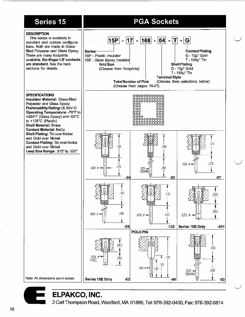
DESCRIPTION This series is available in
standard and custom configurations. Both are made in Glassfilled Polyester and Glass Epoxy. There are many footprints available. Six-finger LIF contacts are standard. See the back sections for details.
SPECIFICATIONS Insulator Material: Glass-filled Polyester and Glass Epoxy Flammability Rating: UL 94V-O Operating Temperature: -76°Fto +284°F (Glass Epoxy) and -65°C to +12s•c (Plastic) Shell Material: Brass Contact Material: BeCu Shell Plating: Tin over Nickel and Gold over Nickel Contact Plating: Tin over Nickel and Gold over Nickel Lead Size Range: .015" to .022"
Note: All dimensions are in inches
PGA Sockets
Series
~- 17
15P - Plastic Insulator 15E - Glass Epoxy lnsulato
Grid Size --~ (Choose from footprints)
-~ Contact Plating G-10µ" Gold T-150µ"Tin
Shell Plating G-10µ" Gold T-150µ" Tin
Terminal Style Total Number of Pins (Choose from selections below) (Choose from pages 19-21)
.165
275
i -0 -02 -07
f .095
.180
t .030
.095
i -08 -132 Series 15E Only -451
POLO PIN
.193
Series 15E Only -83
-+ .025{ .500 SQUARE I I
__J_ -03
ELPAKCO, INC. 2 Carl Thompson Road, Westford, MA 01886, Tel: 978-392-0400, Fax: 978-392-6814
·.__)

,---..
Series 15
DESCRIPTION This series is available in
custom standard and custom configurations. Both are made in Glass-filled Polyester and Glass Epoxy. There are many footprints available.
SPECIFICATIONS Insulator Material: Glass-filled Polyester and Glass Epoxy Flammability Rating: UL94V-0 Operating Temperature: -76°Fto +284°F {Glass Epoxy) and -65°C to +125°C (Plastic) Pin Material: Brass Pin Plating: Tin over Nickel and Gold over Nickel
Note: All dimensions are in inches
PGA Adaptors
Se,;es ~- 17 - 168 - 210 "~,m;nalPlafing
1 SP - Plastic Insulator G - 1 Oµ" Gold 15E - Glass Epoxy Insulator T - 150µ" Tin
Grid Size----~ (Choose from footprints)
Total Number of Pins (Choose from pages 19-21)
000000000000 000000000000 000000000000 000 000 000 000 000 000 000 000 000 000 0000 000 000000000000 000000000000 000000000000
.018 0
Terminal Style {Choose from selections below)
ELPAKCO, INC. 2 Carl Thompson Road, Westford, MA 01886, Tel: 978-392-0400, Fax: 978-392-6814
17

18
Series 15A
DESCRIPTION This series is available in
standard and custom configurations. Both are made in Glass-filled Polyester and Glass Epoxy. There are many footprints to choose from.
SPECIFICATIONS Insulator Material: Glass-filled Polyester and Glass Epoxy Flammability Rating: UL94V-O Operating Temperature: -76°F to +284°F (Glass Epoxy) and -65°C to +125°C {Plastic) Shell Material: Brass Contact Material: BeCu Shell Plating: Tin over Nickel and Gold over Nickel Contact Plating: Tin over Nickel and Gold over Nickel Lead Size Range: .015"to .022"
Note: -12 Terminal style is BeCu One Piece PINTO PIN. Available for 37 x 37 and 39 x 39 only.
Note: All dimensions are in inches
I
Interstitial PGA Sockets
~-Series____=]--
15A - Plastic 15AE - Glass Epoxy
Grid Size --~ (Choose from footprints)
Total Number of Pins (Choose from page 22)
PINTOPIN
.018 •
-14 SOl.0£R STOP
.200
i -29
-~ Contact Plating G -10µ" Gold T-150µ"Tin
Shell Plating G -10µ" Gold T-150µ" Tin
Terminal Style (Choose from selections below)
] .285
.1 20
i
ELPAKCO, INC.
-28
2 Carl Thompson Road, Westford, MA 01886, Tel: 978-392-0400, Fax: 978-392-6814
·J

Series 15 PGA Footprints 11 X 11
00000000000 00000000000 00000000000 000000000 /000000000 00000000000 00000000000
g□gg 00000000000 00000000000
00000000000 gg LJ gg ggo□ g~ 00□0 0000000 00 00 00 00 000 000 800 ooo 00 00 PO oo 00 00 000 000 00 000 00 00 00 00 00 00 000 000 00 000 00 00 00 00 00 00 000 000 00 00 00 00 00 00 00 00 00000000000 60 000 00 00 00 00 00 00 00 00000000000 00000000000 00000000000 00000000000 00000000000 00000000000 00000000000 00000000000 000000000 000000000
96 84 72A 69 68
13 X 13 0000000000000 0000000000000 0000000000000 0000000000000 0000000000000 0000000000000 0000000000000 0000000000000 0000000000000 0000000000000 0000000000000 0000000000000 0000000000000 0000000000000 0000000000000 00000 00000 0000000000000 0000□0000 00000000 000[]000 0000000000000 0000 0000 0000 0000 0000 000 0000000000000 0000 0000 0000 0000 000 000 0000000000000 0000 0000 0000 0000 000 000 0000000000000 0000 0000 0000 0000 0000 0000 0000000000000 0000000000000 0000000000000 00000 00000 0000000000000 0000000000000 0000000000000 0000000000000 0000000000000 0000000000000 0000000000000 0000000000000 0000000000000 0000000000000 0000000000000 0000000000000
169 145 l◄i 133
0000000000000 0000000000000 0000000000000 0000000000000 0000000000000 0000000000000 000 000 000 00000 0000 000 000
000 □ 000 0000 0000 0000 0000 0000 0000 000 000 0000 0000 000 000 000 000 000 000 000 000 000 00000 0000 0000000000000 0000000000000 10000000000000 IO00000000000O 0000000000000 0000000000000
132 12S
14 X 14
00000000000000 00000000000000 00000000000000 00000000000000 00000000000000 00000000000000 00000000000000 00000000000000 loooooooooooooo 00000000000000
ggg□ggg 00000000000000
00000000000000 00000000000000 00000 00000000000000 oooonooo k>oo ooo 000 000
00000000000000 0000 0000 000 000 000 000 00000000000000 0000 0000 000 000 000 000 00000000000000 0000 0000 000 000 000 000 00000000000000 0000 0000 000 000 000 000 00000000000000 0000 0000 000 000 000 000 00000000000000 00000000000000 000 000 000 000 00000000000000 00000000000000 00000000000000 00000000000000 00000000000000 00000000000000 00000000000000 00000000000000 00000000000000 00000000000000 00000000000000 00000000000000
196 160 133 \J2
15 X 15
0000000000000~~ 000000000000000 000000000000000 000000000000000 00000000000000 000000000000000 000000000000000 ooo~goooooooooo ooooooooooooo~g 000000000000000 000000000000000 0000 0000000000 00000000000000 000000000000000 oooo(°oooroo 000 000 000000000000000 0000 0 0000 0000 0000 000 000 000000000000000 0000 0 0000 0000 0000 000 000 000000000000000 0000 0000 0000 0000 000 000 000000000000000 00000 00000 0000 0000 000 000 000000000000000 0000 0000 0000 0000 000 000 000000000000000 0000 0000 0000 0000 000 000 000000000000000 00000 0 0000 0000 0000 000 000 000000000000000 000000000000000 000000000000000 000 000 000000000000000 000000000000000 000000000000000 000000000000000 000000000000000 000000000000000 000000000000000 000000000000000 000000000000000 000000000000000 000000000000000 000000000000000
225 161 176 HS
ELPAKCO, INC. 2 Carl Thompson Road, Westford, MA 01886, Tel: 978-392-0400, Fax: 978-392-6814
19
20
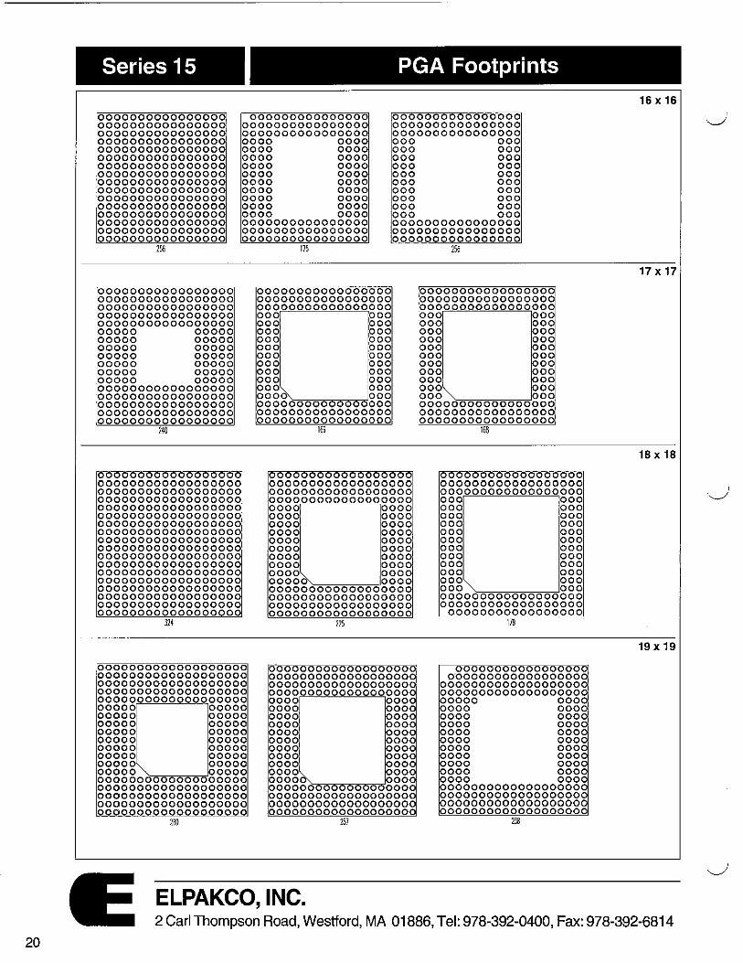
Series 15 PGA Footprints
0000000000000000 0000000000000000 0000000000000000 0000000000000000 0000000000000000 0000000000000000 0000000000000000 0000000000000000 0000000000000000 0000000000000000 0000000000000000 0000000000000000 0000000000000000 0000000000000000 0000000000000000 0000000000000000
000000000000000 0000000000000000 0000000000000000
0000000000000000 0000000000000000 0000000000000000
0000 0000 000 000 0000 0000 000 000 0000 0000 000 000 0000 0000 000 000 0000 0000 000 000 0000 0000 000 000 0000 0000 000 000 0000 0000 000 000 0000 0000 000 000 0000 0000 000 000 0000000000000000 0000000000000000 0000000000000000
0000000000000000 0000000000000000 0000000000000000
256
00000000000000000 00000000000000000 00000000000000000 00000000000000000 00000000000000000 00000 00000 00000 00000 00000 00000 00000 00000 00000 00000 00000 00000 00000 00000 00000000000000000 00000000000000000 00000000000000000 00000000000000000 00000000000000000
24-0
000000000000000000 000000000000000000 000000000000000000 000000000000000000 000000000000000000 000000000000000000 000000000000000000 000000000000000000 000000000000000000 000000000000000000 000000000000000000 000000000000000000 000000000000000000 000000000000000000 000000000000000000 000000000000000000 000000000000000000 000000000000000000
324
0000000000000000000 0000000000000000000 0000000000000000000 0000000000000000000 0000000000000000000 00000 00000 00000 00000 00000 00000 00000 00000 00000 00000 00000 00000 00000 00000 00000 00000 00000 :-,a~~~""-='00000 0000000000000000000 0000000000000000000 0000000000000000000 0000000000000000000 0000000000000000000
160
175
00000000000000000 00000000000000000 00000000000000000 000 000 000 000 000 000 000 000 000 000 000 000 000 000 000 000 000 000 000 000 oooo~~=~c=='ooo 00000000000000000 00000000000000000 00000000000000000
169
000000000000000000 000000000000000000 000000000000000000 000000000000000000 0000 0000 0000 0000 0000 0000 0000 0000 0000 0000 0000 0000 0000 0000 0000 0000 0000 0000 00000:--:-~~~=-='oooo 000000000000000000 000000000000000000 000000000000000000 000000000000000000
225
000000000000000000 000000000000000000 000000000000000000 000000000000000000 0000 000 0000 00 0000 0000 0000 00 0000 00 0000 00 0000 000 0000 00 0000 00 0000 00 0000 ~~~~~=-='000 0000000000 0000000 000000000000000000 000000000000000000 0000000000000000000
257
ELPAKCO, INC.
256
00000000000000000 00000000000000000 000000000 000 000 000 000 000 00 000 000 000 000 000 000 000 000 000 000 000 000 000 000 000 000 =~=~~=-000 00000000000000000 00000000000000000 00000000000000000
168
000000000000000000 000000000000000000 000000000000000000 000 000 000 000 000 000 000 000 000 000 000 000 000 000 000 000 000 000 000 000 000 000 o o o =...,,...,=-==-=--="'=-=-='o o o 000000000000000000 000000000000000000
00000000000000000 179
00000000000000000 0·00000000000000000
0000000000000000000 000000000000000000
0000 000 000 000 000 000 000 000 000 000 000 000 000 000 000 000 000 000 000 000 000 000
000000000000000000 000000000000000000 000000000000000000 0000000000000000000
238
16 X 16
17 X 17
18 X 18
19 X 19
2 Carl Thompson Road, Westford, MA 01886, Tel: 978-392-0400, Fax: 978-392-6814

(
Series 15 PGA Footprints
00000000000000000000 00000000000000000000 00000000000000000000 00000000000000000000 00000000000000000000 00000000000000000000 00000000000000000000 00000000000000000000 00000000000000000000 00000000000000000000 00000000000000000000 00000000000000000000 00000000000000000000 00000000000000000000 00000000000000000000 00000000000000000000 00000000000000000000 00000000000000000000 00000000000000000000 ~0000000000000000000
000000000000 000 00000000000000000000 00000000000000000000 00000000000000000000 0000000 0000 0000000
0000000 000 00000000000000000000 00000000000000000000 00000000000000000000 00000000000000000000
00000 00000 00000 00000 00000 00000 00000 00000 00000 00000 00000 00000
JOO
000000 0000000000 000 000000000000000000000 000000000000000000000 000000000000000000000 000000000000000000000 000000000000000000000 000000000000000000000 000000000000000000000 000000000000000000000 000000000000000000000 000000000000000000000 000000000000000000000 000000000000000000000 000000000000000000000 000000000000000000000 000000000000000000000 000000000000000000000 000000000000000000000 000000000000000000000 000000000000000000000 00000000 000 00000 00
HI
00000 0000000000000000 0000000000000000000000 0000000000000000000000 000000000000000000000 000000000000000000000 000000000000000000000 000000000000000000000 0000000000000000000000 0000000000000000000000 0000000000000000000000
000000000000000000000 000000000000000000000 000000000000000000000
0000 00000 00000 00000 00000 00000 00000 00000 00000 00000 00000 00000 00000 00000 00000 0000 00000 00000 00000 00000 00000 00000 00000 00000 00000 ~~----00000 00000000000000000000 00000000000000000000 00000000000000000000 00000000000000000000 00000000000000000000
00000 .:,-,~~~~~00000 00000000000000000000 00000000000000000000 00000000000000000000 00000000000000000000 00000000000000000000
JOI
00000000000000000000 000000000000000000000 000000000000000000000
00000000000000000000 000000000000000000000 00000 00000 00000 00000 00000 00000 00000 00000
0000 00000 00000 00000
0000 00000 00000 00000 00000 00000 00000 00000 00000 00000 000000000000000000000
00000000000000000000 00000000000000000000
000000000000000000000 00000000000000 0 0
Jl9
000000 0000000000 000 000000000000000000000 0000000000000000000000 0000000000000000000000 0000000000000000000000 0000000000000000000000 000000 000000 000000 000000 000000 000000 000000 000000 000000 000000 000000 000000
00000 000000
JOO
00000000000 000000 00000000000000000000 00000000000000000000 00000000000000000000 0000 ------~oooo 000 0000
0000 0000 0000 0000 0000 0000 0000 0000 0000 0000 0000 0000 0000 0000 0000 0000 0000 0000
000 0000 0000'------____Joooo 000000000000000000000 000000000000000000000 000000000000000000000 000000000000000000000
2/J
0000 0000000000 00000 0000000000000000000000 0000000000000000000000 0000000000000000000000 0000000000000000000000 00000 0000 00000 00000 00000 00000 00000 00000 00000 00000 00000 00000 00000 00000 00000 00000
0000000000000000000000 0000000000000000000000 000000000000000000000 0000000000000000000000 0000000000000000000000 0000000000000000000000 0000000000000000000000 0000000000000000000000 00000000 0000 000 0000
00000 000000 00000 000000
000000 000000 0000000000000000000000 0000000000000000000000 0000000000000000000000 0000000000000000000000 000000000000000000000
0 000 0 00000000000 J8J
00000 00000 00000 0000 00000 0000 00000 0000 0000000000000000000000 0000000000000000000000 0000000000000000000000
000000000000000000000 00000000000000000 0000
340 ™
ELPAKCO, INC.
20 x20
21 X 21
22 X 22
2 Carl Thompson Road, Westford, MA 01886, Tel: 978-392-0400, Fax: 978-392-6814 21
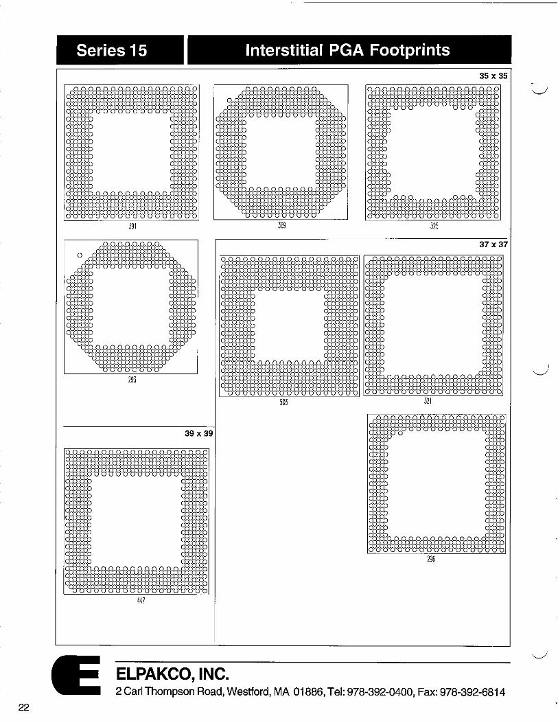
Series 15 Interstitial PGA Footprints
35 X 35
369
37 X 37
293
39 X 39
ELPAKCO, INC. 2 Carl Thompson Road, Westford, MA 01886, Tel: 978-392-0400, Fax: 978-392-6814
22
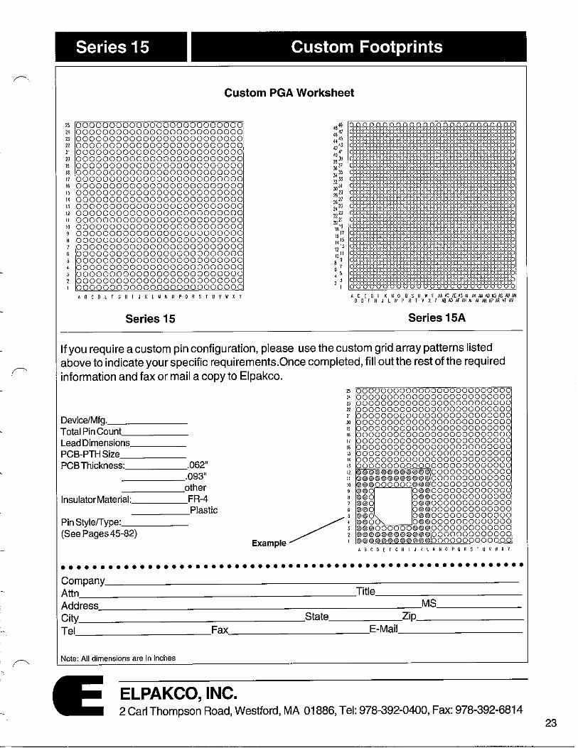
Custom Footprints Series 15 I
Custom PGA Worksheet
25 0000000000000000000000000 18,~ 0000000000000000000000000000000000000000000000000 21 0000000000000000000000000 <6 47 ooooooooooooooodHfPoooooooooooooooooooooooooooo 2J 0000000000000000000000000 ., ,s o0o0o0o0o0o0o0o0o0o0o0o0o0o0o0o0o0o0o0o0o0o0o0o00 21 0000000000000000000000000 1243 oooooooooooa°oOaOOOOOOOQOOOOOOOOOOOOOQOOOQOQOOOOO 21 0000000000000000000000000
40~ 0000000000000000000000000
2J 0000000000000000000000000 OOOOOOOOOOOOOOOOOOOOOOOOOOOQOOOQOQOOOOOOOOOQOQOQO
19 0000000000000000000000000 ;i1 ooooooooooo°ooooooooooooooooooooooooooooooooooo°o
13 0000000000000000000000000 JI )5 OOQOQOQOOOOOOOOOOOOOQOQOOOOOOOQOOOOOOOQOOOOOOOOOO
17 0000000000000000000000000 JZ ll OOOOOOOOOOOOOOOOOOQOOOOOOOOOOOOOOOOOOOOOOOOOOOOOO
16 0000000000000000000000000 JOJI ooooooooooooooooooooooooooooooooooooooo°ooooooooo
I) 0000000000000000000000000 2829 a0
o0
o0
o0
o0
a0
a0
a0
o0
o0
o0
o0
o0
o0
a0
o0
o0
o0
o0
o0
o0
o0
o0
a0
o II 0000000000000000000000000 2627 0
o0
o0
o0
o0
o0
o0
o0
o0
o0
o0
o0
o0
o0
o0
o0
o0
o0
o0
o0
o0
o0
o0
o0
o0
13 0000000000000000000000000 2, 25 o0
o0
o0
a0
o0
o0
o0
o0
o0
o0
o0
o0
o0
o0
o0
o0
o0
o0
o0
a0
o0
o0
o0
a0
o 12 0000000000000000000000000 222) ooooooooooooooooooooooooooooooooooooo~1Wooooooo
II 0000000000000000000000000 0000000000000000000 0000 2021 o0o0o0o0o0o0o0o0o0o0o0o0o0o00ao0o0o0o0o0o0o0o0o0o
10 0000000000000000000000000 1819 o0
o0
o0
o0
o0
o0
o0
o0
o0
o0
o0
o0
o0
o0
o0
o0
o0
o0
o0
o0
o0
o0
o0
o0
o 9 0000000000000000000000000 1617 0000000000000000000000000000000000000000000000000 a 0000000000000000000000000 Hl5 0000000000000000000000000 7 0000000000000000000000000 1213 OOOOOOQOOOOOOOOOOOOOOOOOOOOOOOOOOOOOOOOOOOOOOOOOO
6 0000000000000000000000000 1011 0000000000000000000000000000000000000000000000000
5 0000000000000000000000000 8 9 o0
o0
o0
a0
o0
o0
o0
o0o~
0o
0o
0o
0o
0o
0o
0o
0o0
o0
o0
o0
o0
o0
o0
o
' 0000000000000000000000000 6 7 OOOOOOOOOOOOOOOOO o0o0o0o0o0o0o0o0o0o0o0o0o0o0o0o
3 0000000000000000000000000 4 5 OOOOOOOOOOOOOOOOOOOOOOOOQOOOOOQOQOOOOOOOOOOOOOOOO
2 0000000000000000000000000 2 ) ooooooooooooooooo°ooooooooooooooooooooooooooooooo
l 0000000000000000000000000 I 0000000000000000000000000000000000000000000000000
ABCD[F GHIJKLMNOPQRS! U V W X Y AC [GI K MO OSU WY MACAEIG~AX/J.IIOl,QISAIJAW B O f H J L N P R I V X Z Ill ID I< AH AJ '1. Ni If> Al! Al AV
Series 15 Series 15A
If you require a custom pin configuration, please use the custom grid array patterns listed above to indicate your specific requirements.Once completed, fill out the rest of the required information and fax or mail a copy to Elpakco.
25 0000 00000000000000000001~ 11 000000000000000000000000 2) 000000000000000000000000 n 00000000000000000000000~§
Device/Mfg. 21 0000000000000000000000 00 20 0 000000000 000000000000 000
Total Pin Count 19 0000000000 0000000000000~~ ,s 000000000000000000000000
Lead Dimensions 17 0 00000000000000000000000c
PCB-PTH Size 16 0 00000000000000000000000§ 15 0 00000000000000000000000
PCB Thickness: .062" " o~ggoooooooooooooooooooo~ 13 00 0000000000000 0000 000
.093" 12 ©©©®@@@®®0©@~00000000000 11 ©®@@©@®®©©®© 00000000000
other 10 @©®000000@@®0000000000000 g ~-□••0000000000000
lnsu la tor Material: FR-4 8 ®© 0©@0000000000000 7 ©© 0@@0 000000000000
Plastic 6 @® 0®®0000000000000
Pin Style/Type: 5 @®O 0®©0000000000000
Example~ i ©00 0©©0000000000000
(See Pages 45-82) @©@00 ©©@0000000000000 ©@®®®@©@©©©@ 0000000000000 @@©©@®®©@®@© 0000000000000 ABCDCTCHIJ K LMNOPQRS T UVWXY
•••••••••••••••••••••••••••••••••••••••••••••••••••••••••••• Company Attn Title
Address MS
City State Zip
Tel Fax E-Mail
Note: All dimensions are in inches
ELPAKCO, INC. 2 Carl Thompson Road, Westford, MA 01886, Tel: 978-392-0400, Fax: 978-392-6814
23

i ,r"
Series 18
DESCRIPTION All insulators are end-to-end
and side-to-side stackable.
SPECIFICATIONS Insulator Material: Glass-filled Polyester Flammability Rating: UL 94V-O Operating Temperature: -55°C to +125°C Pin Material: Brass Pin Plating: Tin over Nickel and Gold over Nickel Thickness: .100" to .112" for open frame only
DIMENSIONS
No.of 'A' 'B' 'C' Pins 6 .300 8 .400 10 .500 14 .700 16 .800 .300 .400 18 .900 20 1.00 22 1.10 24 1.20 28 1.40 22 1.10 .400 .500 24 1.20 24 1.20 28 1.40 32 1.60 36 1.80 .600 .700 40 2.00 48 2.40 50 2.50 52 2.60 .900 1.00 64 3.20
Note: All dimensions are in inches
Adaptor Sockets
Series
~- 6 -32
18 - Open Frame DIP 188 - Closed Frame DIP
DIP Spacing 3 - .300" 4- .400" 6 - .600" 9 - .900" Total Number of Pins
6 - 64
T = ""
B
·l_ Terminal Plating G - 10µ" Gold T - 150µ" Tin
Terminal Style (Choose from selections below)
A _____..,J•1 H" ) H H H 0 r
C
l_ m oooooonno " _l
_j_ -------.100 lo .1 12
T
.018
.155
~ t
-09
.016 j I .156
_J_ -11
.018 ~ .156
__ _,_!_ -505
-290
-385
ELPAKCO, INC. 2 Carl Thompson Road, Westford, MA 01886, Tel: 978-392-0400, Fax: 978-392-6814
25

26
Series 19
DESCRIPTION Series 19 is available in
custom configurations. The precision screw-machine outer shell and the four-finger BeCu inner contact allow for easy IC insertion.
SPECIFICATIONS Insulator Material: Glass-filled Polyester Flammability Rating: UL 94V-O Operating Temperature: -55°C to +125°C Shell Material: Brass Contact Material: BeCu Shell Plating: Tin over Nickel and Gold over Nickel Contact Plating: Tin over Nickel and Gold over Nickel Lead Size Range: .015" to .022" diameters Note: All dimensions are in inches
Series SD
DESCRIPTION Series SD is available in a 64-
position format. The Shrink-DIP socket insulator has an open frame design.
SPECIFICATIONS Insulator Material: Glass-filled Polyester Flammability Rating: UL94V-O Operating Temperature: -65°C to +125°C Shell Material: Brass Contact Material: BeCu Shell Plating: Tin over Nickel and Gold over Nickel Contact Plating: Tin over Nickel and Gold over Nickel Lead Size Range: .015" to .022" diameters
Note: All dimensions are in inches
Crystal Oscillator Sockets
Series ----' 19 - Crystal Oscillator
DIP Spacing ---....J 3 - .300" 4-.400" 6 - .600" 9 - .900" Total Number of Pins
4 8
Insulator Size- 8
14 16
Terminal Plating G-10µ" Gold T-150µ"Tin
Contact Plating G-10µ"Gold T -150µ'' Tin
Terminal Style 04
Shrink-DIP Sockets
Series SD - Shrink-DIP
Contact Plating G-10µ"Gold T-150µ"Tin
Total Number of Pins 64
Row Spacing 750- .750"
~ r--070 TYP.
Shell Plating G-10µ"Gold
Terminal Style T - 150µ" Tin 04S
, 00000000000000000000000000000000 T )~ I I .840
1__ 00000000000000000000000000000000 J_ 1-- 2.252 ... 1
5
c:::==================:JJ_ i-
ELPAKCO, INC. 2 Carl Thompson Road, Westford, MA 01886, Tel: 978-392-0400, Fax: 978-392-6814
I '-......,/

i .•. r.
Series 20 Elevated Sockets
DESCRIPTION All insulators are end-to-end
and side-to-side stackable. Series 20 is available in sizes 6 to 64 in both open and closed frame. The precision screwmachine outer shell and the fourfinger BeCu inner contact allow for easy IC insertion. A variety of stand-off heights are available.
Series
~QJ- 6 -28
20- Open Frame DIP 208 - Closed Frame DIP
DIP Spacing 3 - .300" 4- .400"
• 21 · T ·l Terminal Plating G-10µ" Gold T-150µ" Tin
Terminal Plating G -10µ" Gold T-150µ" Tin
'----Terminal Style 6 - .600" 9 - .900" Total Number of Pins (Choose from selections below)
6 - 64
SPECIFICATIONS Insulator Material: Glass-filled ~~~~~~~~~~~;rg:~ Polyester T Flammability Rating: UL94V-O B Operating Temperature: -55°C to J_ +125°C -EIT1Q@QQlTIEmg[QJ
Shell Material: Brass Contact Material: BeCu Shell Plating: Tin over Nickel and Gold over Nickel Contact Plating: Tin over Nickel and Gold over Nickel Lead Size Range: .015" to .022"
DIMENSIONS
No.of 'A' '8' 'C' Pins 6 .300 8 .400 10 .500 14 .700 16 .800 .300 .400 18 .900 20 1.00 22 1.10 24 1.20 28 1.40 22 1.10 .400 .500 24 1.20 24 1.20 28 1.40 32 1.60 36 1.80 .600 .700 40 2.00 48 2.40 50 2.50 52 2.60 .900 1.00 64 3.20
Note: All dimensions are in inches
I
TI OSJo-'' J I j .0400l
I .118 .018 0-- f
ELPAKCO, INC.
1-
T B
J_
A 7 H " oonon "
00000 " onor o
t C
_l _l_ -------.100 to .112 T
.1 70
"' __ .,__f -16
TYPE 'A' -19 .236 -20 .315 -21 .402 -22 .472 -23 .594 -24 .699
-19 to -24
2 Carl Thompson Road, Westford, MA 01886, Tel: 978-392-0400, Fax: 978-392-6814 27

28
.050 11 X .050 11
DESCRIPTION Elpakco's unique low cost
PINTO PIN has been designed as a low insertion force* onepiece three-finger Beryllium Copper pin. The head diameter is only .034" which makes the PINTO PIN an ideal component for Interstitial, Shrink-DIP and 2mm spacing applications. This one-piece pin is available in a variety of plating options which include Gold and Tin.
The spacing is on a .050" grid. The PINTO PIN socket strips will accept lead sizes .015" to .022" diameters as well as .016" square. The two socket types can be mated together to obtain a desired board-to-board height of .265". These .050" spacing socket/header strips can withstand Solder Reflow, lnfared and Vapor Phase processes.
SPECIFICA TTONS Insulator Material: Stanyl 46 Nylon TE 250F6 Rated to UL94V-0 Process Temperature: -65°C to +125°C Pin Material: One Piece Beryllium Copper per QQ-C-530 Gold: PerMIL-G-45204 Tin: PerMIL-T-10727 Nickel: Per QQ-N-290 Lead Size Range: .015" to .022" diameters Insertion Force: 20g Avg.
Note: All dimensions are in inches
Pinto Pin Socket Strips & 1066 Headers
Series - -----~~
21 • S0 • 1
2-~ PlnPlallng
21 - Single Row Strip G -10µ" Gold over 150µ" Nickel 21 D - Dual Row Strip T - 200µ' Tin over 150µ" Nickel 22 - Single Row Header Terminal Style 22D - Dual Row Header 12 - Pinto Pin Socket
Total Number of Pins 1-50 (Single Row) 2-100 (Dual Row)
Insulator Drawings
1066 - Header Pin
I Series 21 I
~~~~~~~~~~~~~~~~~~~~~~~~~~~~~~~~~~~~~~~~~~~~~~~~~~
Terminal Styles
I Type-1066
Insertion Force - 20g Avg. with .0180 Pin
~ .020/.024
.034 ± DIA_-TlrrT1IJ---,--f -
.076 ± .002
3-flNG£RS ACCEPT .QI 5"-.022" DIA. PINS
3 RETENTION BARBS I -.038 OIA. I
.150
SOLDER STOP~ ~---_,__
.026 'E
.115 .OIB 1 .001 DIA.
Type-12
.285
ELPAKCO, INC. 2 Carl Thompson Road, Westford, MA 01886, Tel: 978-392-0400, Fax: 978-392-6814
··J

r
·~.
!
i ' 1 I ·-·
r
Series SMC
DESCRIPTION The Surface Mount Decoupling
capacitor sockets are available in a number of different sizes. The ground plane web covers the entire surface. The capacitors are soldered directly to the VCC and GND pads.The precision screwmachine outer shell and the fourfinger BeCu inner contacts allow for easy IC insertion.
SPECIACATIONS Insulator Material: Glass Epoxy Laminate Flammability Rating: UL94V-O Operating Temperature: -55°C to +125°C Thickness: .062" Shell Material: Brass Contact Material: BeCu Shell Plating: Tin over Nickel and Gold over Nickel Contact Plating: Tin over Nickel and Gold over Nickel Lead Size Range: .015" to .022"
DIMENSIONS
No.of 'A' '8' 'C' Pins 6 .300 8 .400 10 .500 14 .700 16 .800 .300 .400 18 .900 20 1.00 22 1.10 24 1.20 28 1.40 22 1.10 .400 .500 24 1.20 24 1.20 28 1.40 32 1.60 36 1.80 .600 .700 40 2.00 48 2.40 50 2.50 52 2.60 .900 1.00 64 3.20
Note: All dimensions are in inches
Decoupling Capacitor Sockets
Series ~J3-SMC - Decoupling Caps
DIP Spacing 3 - .300" 4- .400" 6 - .600" 9 - .900"
28 - 04 - T - G -~ Capacitor .1 - .1 pf .01 - .01 pf
Contact Plating G - 10µ" Gold T-150µ" Tin
Total Number of Pins ___ __, Shell Plating G -10µ" Gold
6- 64 Terminal Style T - 150µ" Tin
T 8
J_
-04
t .165
.020 lil--f!T ___ .1...,__80
~- ! -08
(Choose from selections below)
-07
.062
J_
~~,
,193
~-~
,025; .500 SQUARE I __J_
-03
-132
ELPAKCO, INC. 2 Carl Thompson Road, Westford, MA 01886, Tel: 978-392-0400, Fax: 978-392-6814
29

30
Series ZZ
DESCRIPTION Elpakco Series ll is available
in any size. Series 20 is also avaliable in a removable carrier design. Call the factory for more details on special designs. The precision screw-machine outer shell and the four-finger BeCu inner contact allow for easy IC insertion.
SPECIFICATIONS Insulator Material: Glass Epoxy Laminate Flammability Rating: UL 94V-O Operating Temperature: -55°C to +125°C Shell Material: Brass Contact Material: BeCu Shell Plating: Tin over Nickel and Gold over Nickel Contact Plating: Tin over Nickel and Gold over Nickel Lead Size Range: .015" to .022"
DIMENSIONS
No.of 'A' 'B' 'C' Pins
14 .600 .700 16 .700 .800 18 .800 .900 20 .900 1.00 .100 24 1.10 1.20 28 1.30 1.40 40 1.90 2.00 60 2.90 3.00
Note: All dimensions are in inches
C
Zig Zag Sockets
___,-i- 18 Series zz -Zig Zag Sockets
Total Number of Pins 14 28 16 40 18 60
- 04 -
Terminal Style
-~ L Contact Plating
G-10µ" Gold T-150µ" Tin
Shell Plating G -10µ" Gold T-150µ" Tin
20 (Choose from selections below) 24
,-~ .s=i_i t ©00000000000®® 2 0
.ffiu©®OOOOOOOOOOO® .O
~ h1Jo TYP. J--Aso TYP.
.193
-04
-+ .025 j1f .360
SQUAREW - t -02
.125
t
.062
c::J_J_ f
.030
095
.095
t
.1 70
--1.03 -83 -98 Press-fit in .030 :1: .003 -99
ELPAKCO, INC. 2 Carl Thompson Road, Westford, MA 01886, Tel: 978~392-0400, Fax: 978-392-6814
·-..__,1'

,r'
-.
~-
Series RA
DESCRIPTION Series RA is available in Glass
filled Polyester insulators. The Precision terminals are plated with Tin shells and Gold contacts. Other varities are available upon request.
SPECIFICATIONS Insulator Material: Glass-filled Polyester Flammability Rating: UL94V-O Operating Temperature: -65°C to +125°C Shell Material: Brass Contact Material: BeCu Shell Plating: Tin over Nickel Contact Plating: Gold over Nickel Lead Size Range: .015" to .022" diameters
DIMENSIONS (Style A & B)
No. of 'A' 'B' 'C' Pins 14 .700 .400 .300 16 .800 .400 .300
18 .900 .400 .300 20 1.00 .400 .300 28 1.40 .400 .300
DIMENSIONS (StyleC)
No. of 'A' 'B' 'C' Pins 28 1.40 .700 .600 32 1.60 .700 .600 40 2.00 .700 .600
Note: All dimensions are in inches
Right Angle LED Sockets
~~-A-~ Series----- Total Number of Pins RA - Right Angle LED 14
Style 16 A- .300 18 B-.100 20 C- .300
7 r.125
.17J -i---.218 J OO
.020 f/J
Style - A (.300 DIP Spacing)
7 r-125
.020 rt,
Style - C (.600 DIP Spacing)
.020 0
.100
Style - B (.300 DIP Spacing)
ELPAKCO, INC. 2 Carl Thompson Road, Westford, MA 01886, Tel: 978-392-0400, Fax: 978-392-6814
31

34
Series MS
DESCRIPTION The series MS mates with
Elpakco .025" square posts pin headers, (Series PH). There are five choices. The standard color is Black.
SPECIFICATIONS Insulator Material: Glass-filled Polyester Flammability Rating: UL 94V-O Operating Temperature: -65°C to +12s0 c Contact Material: Phosphor Bronze Contact Plating: Gold over Nickel and Tin over Nickel
Note: All dimensions are in inches
Mini Shunts
Series-----MSA - Mini, Closed Top MSB - Mini, Open Top, Stackable MSC - Micro, Open Top, Stackable MSD - Double Ended MSBH - Mini, Open Top with Handle
Contact Plating G - Gold Flash T-150µ"Tin
MSA MSB MSC L L I
.256 □ LJ .256 ~ □ .1~ □ 0200(-. _j f-._095 q,200f-- _j f-._.096 --bo□f-· _j f-._096
MSD MSBH
~ 3~ □ {~ 99
q_200(-. _j f--.C96 --booi-- -1 ka96• • 4
ELPAKCO, INC. 2 Carl Thompson Road, Westford, MA 01886, Tel: 978-392-0400, Fax: 978-392-6814
\.._,,/

Series PH .02511 Square Post Pin Header
DESCRIPTION The Elpakco Pin headers have
molded in stand-offs. They are available in single, dual and triple rows on .100" centers. Series PH is end-to-end stackable on .100" centers. This series mates with Elpakco series RS.
SPECIFICATIONS Insulator Material: Glass-filled Polyester Flammability Rating: UL94V-O Operating Temperature: -55°C to +125°C Pin Material: Copper Alloy Pin Plating: Tin over Nickel and Gold over Nickel
Note: All dimensions are in inches
~- PH1
Series~ PH - Pin Headers
Rows------_J PH1 - Single, Straight PH2 - Dual, Straight PH3 - Triple, Straight P1 A - Single, Right Angle P2A - Dual, Right Angle P3A - Triple, Right Angle
PH1
o!° i +w ~D~ P1A
ELPAKCO, INC.
~Plnlength A-C=.240"
D=.120" B- C=.318"
D=.135" Pin Plating
U - 10µ" Gold T-150µ" Tin
Total Number of Pins 1 - 40 - Single Row 4 - 80 - Dual Row 6 - 120 - Triple Row
.1
P2A
PH3 .100
_i C
--+
7 =-.::::
1
==::!J .100 --j DJ
P3A
2 Carl Thompson Road, Westford, MA 01886, Tel: 978-392-0400, Fax: 978-392-6814 35

-_r·
Series 38
DESCRIPTION The 108-pin connectors are
available in both straight and right angle types. The body is made from a Glass-filled Polyester thermoplastic. The polarization slots cause good positive registration. Gold plated pins allow for good wire wrapping. The closed entry socket prevents accidental mating with larger contacts. The chamfered pins allow for easy mating.
SPECIFICATIONS Insulator Material: Glass-filled Polyester Flammability Rating: UL94V-O Color: Black Operating Temperature: -55°C to +125°C Contact Material: Brass Contact Plating: Gold over Nickel
Note: All dimensions are in inches
108 - Pin Male and Female Connectors
Series~ 1381 -108 -M - L Pln PlaUng
38 - 108-Pin Connectors G -10µ" Gold
Style Total Number of Pins 108 F - Female, Straight
M - Mate, Right Angle
4.175
~~~ss~z~~~zs~ssa~am~~Ram~mz ~s~~ • z~~a ~-••••~~ma••e••••• ••••• m~ • ••Rmm•••••
----------------~-------------------J.50□ ---------i
.125 ,
.39o
t .J_: .295
~------------n I .22s
-....U...--------------"--._J_ -r-D T ~~
I ~]' _L_
~m I I 4.435 ,.2001
P/N: 38-108-F-G
L Ir----;::\:'"= .. = .. = .... == .. = .... = .. == .. == .... == .. == .... ::::.:::::: .. :::: .... :::: .. :::: .... :::: .. :::::: .. ::::: .... :::: .. :::: .. ::::: .... :::;: .. ::::: .... :::: .. :::;: .. ::::: .. :/:;----,
A15 - ~~~~~~--~-m~•-B••••am• ~~R®B•• •--9~~ • ••- •••••-•m• ••s•• ••••••~•••• ••• •••m
II. --I i---.100
000 _/
120 •"-,._ ___________ 025_so_~--=-i
~mm 1111 m 1111111 mm 11 1m1111~± 4-40 THR(AO
/
P/N: 38-108-M-G
too~ 2~
.060 1-- .600
ELPAKCO, INC. 2 Carl Thompson Road, Westford, MA 01886, Tel: 978-392-0400, Fax: 978-392-6814
37

Terminals Stamped Terminals
SPECIFICATIONS SP1-X Terminal Material: Brass Alloy 360 1/2 Hard, .025 thick Terminal Plating: 1 Oµ" Gold over
""~'
1.010 1 50µ" Nickel or 200µ" Tin over .300
~ : 100µ" Nickel Tolerances: Lengths - ±.005 I:> .025 SQ
Diameters - ±.002 ' Angles- 2° .062 .034
Range: Press-fit into .035 Mtg. Hole
Note: All Dimension are in inches Plating Options: G - Gold and T- Tin
SPECIFICATIONS SP2-X Terminal Material: Brass Alloy 360, 1/2 Hard, .025 thick Terminal Plating: 10µ" Gold over 50µ" Nickel or 200µ" Tin over
' 1· 0: .540 1 100µ" Nickel
Tolerances: Lengths - ±.005 Diameters - ±.002 -~C "1! I> .025 SO. Angles - 2° i ,
' Range: Press-fit into .035 Mtg. T:1 l-.015 I Hole
Note: All Dimension are in inches Plating Options: G - Gold and T-Tin
SPECIFICATIONS SP3-X Terminal Material: Brass Alloy 360, 1/2 Hard, .025 thick Terminal Plating: 10µ" Gold over 50µ" Nickel or 200µ" Tin over _j_1 · .685 1 100µ" Nickel
or Tolerances: Lengths - ±.005
Diameters - ±.002 .050 c 11 [> .025 so . Angles - 2° )/ • Range: Press-fit into .035 Mtg. T-:lh015
Hole
Note; All Dimension are in inches Plating Options: G - Gold and T- Tin
SPECIFICATIONS 82S-3-F-H-L Terminal Material: Brass Alloy
[: ... ,.J J
360, 1/2 Hard L ±.005 Terminal Plating: 10µ" Gold over
H ±.005 , .065 r-50µ" Nickel or 200µ" Tin over
t Crimp 100µ" Nickel 3 - Star Tolerances: Lengths - ±.005
I I
.042 • STARS)=~ [J
1 - No Star .025 SQ. Cl fl If
Diameters - ±.002,
• II Platlng
Angles - 2° F-Tin
Range: Press-fit into .037 Mtg. G-Gold
Hole 60' Above Board Height
I Total Length
Note: All Dimension are in inches
·-.....
ELPAKCO, INC. 2 Carl Thompson Road, Westford, MA 01886, Tel: 978-392-0400, Fax: 978-392-6814
38

r
i_
I ·-.r
Terminals Crimped Terminals ,-------------...-------------------------------------------------------~ SPECIFICATIONS Terminal Material: Phosphor Bronze Terminal Plating: 1 0µ" Gold over 50µ" Nickel or 200µ" Tin over 100µ" Nickel Tolerances: Lengths - ±.005
Diameters - ±.002 Angles - 2°
Range: Press-fit into .021 Mtg. Hole
SPECIFICATIONS Terminal Material: Phosphor Bronze Terminal Plating: 10µ" Gold over 50µ" Nickel or 200µ" Tin over 100µ" Nickel Tolerances: Lengths - ±.005
Diameters - ±.002 Angles -2°
Range: Press-fit into .021 Mtg. Hole
SPECIFICATIONS Terminal Material: Phosphor Bronze Terminal Plating: 10µ" Gold over 50µ" Nickel or 200µ" Tin over 100µ" Nickel Tolerances: Lengths - ±.005
Diameters - ±.002 Angles-2°
Range: Press-fit into .021 Mtg. Hole
Note: All Dimension are in inches
A ---t------250 --1
.020 ~ * LA .018 ;
Plating Options: G-Gold andT- Tin
~ .350 ....
1
.020~040 , ;---i__j ~~/ ~
.018 lb
Plating Options: G- Gold and T- Tin
.018 (/J
Plating Options: G- Gold and T-Tin
ELPAKCO, INC.
.025~
SECTION A - A
E0250
E0350
.025~
SECTION A - A
E0600
.025~
SECTION A - A
2 Carl Thompson Road, Westford, MA 01886, Tel: 978-392-0400, Fax: 978-392-6814 39

40
Connectors
SPECIFICATIONS Insulator Material: Polypropylene Flammability Rating: UL 94V-O Pin Material: Brass Pin Plating: Gold over Copper
DIMENSIONS
P/N 'A' E2871-01 .200 E2871-02 .250 E3771-01 .400 E3771-02 .500 E2872-01 .200 E2872-02 .250 E2872-03 .300 E2872-04 .400 E2872-05 .500 E3360-01 .200 E3360-02 .250 E3360-03 .300 E3360-04 .400 E3360-05 .500
Note: All dimensions are in inches
Swager
SPECIFICATIONS Swager Material: Cast Iron Swager: Manual pressure cam action with a 5" throat depth. Call the factory for Anvil & Punch sizes.
.161 • TYP
Shorting Plugs .
L__I E_28~7~1 _0__,2 j - G Series ~---'I Basic P/N
Pin Plating G -10µ" Gold
-[[_ Insulation Color
10- Black 12 - Red 16 - Blue
1--111----.040 ~
#E2871
#E2872 Non-Insulated #E3360 Non-Insulated
Terminal Swager
Serk,s~ SW1 - Terminal Swager
L1.ooo =:J_J_ llth:J:200 0 THROAT
~2~~500 Q[[P 1/2 - 24 THREAD
I I 2.250 I .500~
j I 2.250 I .500~
ELPAKCO, INC. 2 Carl Thompson Road, Westford, MA 01886, Tel: 978-392-0400, Fax: 978-392-6814

Connectors
SPECIFICATIONS Insulator Material: Teflon Pin Material: Beryllium Copper Heat Treated (Hour Glass Type) Pin Plating: Gold over Nickel or Tin over Nickel For Panel Thickness: .031 to .125 Capacitance (pF): 1.0
.172 Mtg. Hole Dia. for .080 Dia. Pins
Note: All dimensions are in inches
Teflon Press Mount Style Jacks
142861 - G -
Series-------~! ~Insulation Colo, 10 - Black 4286 - Basic Part Number
.050
~ .175
t
.116
Pin Plating __ ......J
G - Gold over Nickel T - Tin over Nickel
.350 MIN. HOLE DEPTH WITH SMALLER HOLE BENEATH
ONE PIECE JACK FUNl~EL - SHAPED ENTRY
.185 ±.001 1/i
11 - Brown 12 - Red 13 - Orange 14-Yellow 15 - Green 16 - Blue 17 - Violet 18- Gray 19 - White (Standard)
.200 REF.
7
ELPAKCO, INC. 2 Carl Thompson Road, Westford, MA 01886, Tel: 978-392-0400, Fax: 978-392-6814
41
42
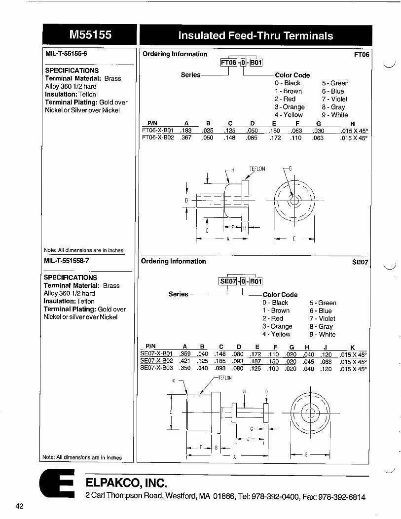
M55155
MIL-T-55155-6
SPECIFICATIONS Terminal Material: Brass Alloy 360 1 /2 hard Insulation: Teflon Terminal Plating: Gold over Nickel or Silver over Nickel
Note: All dimensions are in inches
MIL-T-551558-7
SPECIFICATIONS Terminal Material: Brass Alloy 360 1 /2 hard lnsulation:Teflon Terminal Plating: Gold over Nickel or silver over Nickel
Note: All dimensions are in inches
Insulated Feed-Thru Terminals
Ordering Information
~-~-~ FT06
Series Color Code 0 - Black 5 - Green 1 - Brown 6 - Blue 2 - Red 7 - Violet 3-Orange 8- Gray 4-Yellow 9-White
P/N A B C D E F G H FT06-X-B01 .193 .025 .125 .050 .150 .063 .030 .015 X45° FT06-X-802 .367 .050 .148 .085 .172 .110 .063 .015 X45°
t TEFLON
/
Ordering Information SE07
•t~ Series------ Color Code
P/N A B C D E SE07-X-B01 .359 .040 .148 .080 .172 SE07-X-B02 .421 .125 .165 .093 .187 SE07-X-803 .350 .040 .093 .080 .125
K TEFLON
H
0 - Black 1 - Brown 2-Red 3-Orange 4-Yellow
F G .110 .020 .150 .020 .100 .020
D
H
5- Green 6 - Blue 7 - Violet 8-Gray 9 -White
J .040 .120 .045 .068 .040 .120
K .015X 45° .015 X 45° .015 X45°
ELPAKCO, INC. 2 Carl Thompson Road, Westford, MA 01886, Tel: 978-392-0400, Fax: 978-392-6814
0

('.
·-
M55155 Insulated Feed-Thru Terminals
MIL-T-55155-8
SPECIFICATIONS Terminal Material: Brass Alloy 360 1/2 hard Insulation: Teflon Terminal Plating: Gold over Nickel or Silver over Nickel
Note: All dimensions are in inches
MIL-T-55155-3
SPECIFICATIONS Terminal Material: Brass Alloy 3601/2 hard Insulation: Teflon Terminal Plating: Gold over Nickel or silver over Nickel
Note: All dimensions are in inches
Ordering Information .,-~ Serles Color Code
0 - Black 1 -Brown 2-Red 3-Orange 4-Yellow
P/N A B C D E F SE08-X-B01 .350 .040 .148 .040 .172 .100 SE08-X-B02 .350 .040 .093 .040 .1 25 .100
G
Ordering Information
~l~ Series----T~ Color Code
0 - Black
P/N A B C FT03-X-B01 .375 .040 .148 FT03-X-B02 .515 .040 .148 FT03-X-B03 .675 .125 .165 FT03-X-B04 .515 .040 .093 FT03-X-B05 .343 .040 .093
H
t C
D .040 .040 .040 .040 .040
1 - Brown 2 - Red 3-Orange 4-Yellow
E F G .172 .100 .125 .172 .100 .210 .187 .150 .200 .125 .100 .210 .125 .100 .125
ELPAKCO, INC.
5-Green 6-Blue 7 - Violet 8- Gray 9 -White
G .015 X 45° .015 X45°
5-Green 6- Blue 7 - Violet 8 - Gray 9-White
H .015 X45° .D15X45° .015 X 45° .015 X45° .015 X45°
SE08
FT03
2 Carl Thompson Road, Westford, MA 01886, Tel: 978-392-0400, Fax: 978-392-6814 43

44
M55155
MIL-T-55155-4
SPECIFICATIONS Terminal Material: Brass Alloy 3601/2 hard Insulation: Teflon Terminal Plating: Gold over Nickel or Silver over Nickel
Note: All dimensions are in inches
SPECIFICATIONS Terminal Material: Brass Alloy 360 1/2 hard Insulation: Teflon Terminal Plating: Gold over Nickel or silver over Nickel
Note: All dimensions are in inches
Insulated Feed-Thru Terminals
Ordering Information ·-~-~ Series----_, Color Code
FT04
0 - Black 5 - Green 1 - Brown 6 - Blue 2 - Red 7 - Violet 3 - Orange 8 - Gray 4-Yellow 9 - White
P/N A B C D E F G H J K L FT04-X-801 .500 .040 .148 .080 .172 .100 .210 .020 .040 .100 .015 X 45° FT04-X-B02 .836 .125 .148 .093 .172 .230 .250 .020 .040 .093 FT04-X-B03 .500 .040 .093 .080 .125 .100 .210 .020 .040 .100
L ~ ~ TEFLON
C D
C+----
t
Ordering Information
ffrosil~ Series-~--T~ Color Code
P/N A B C FT05-X-B01 .225 .040 .093 FT05-X-B02 .310 .050 .120 FT05-X-B03 .367 .050 .148
J_ t
---D
T
D .040 .040 .085
H
E
0 - Black 1- Brown 2-Red 3-Orange 4-Yellow
F G .125 .060 .030 .130 .053 .030 .172 .110 .063
TEFLON
/
E
5-Green 6- Blue 7 - Violet 8- Gray 9-White
H .015 X 45° .015 X45° .015 X45°
.015 X45°
.D15X45°
FT05
ELPAKCO, INC. 2 Carl Thompson Road, Westford, MA 01886, Tel: 978-392-0400, Fax: 978-392-6814

' . . .,
Terminals
SPECIFICATIONS Pin Material: Beryllium Copper Alloy 172 1/2 HD and Heat Treated After Forming Tolerances: Lengths - ±.005
Diameters - ±.002 Angles -2°
Note: All dimensions are in inches
98
.062 r/J
.059 ¢ BARB .055 r/J
.020
~ ~ 1.oso
.020 ¢
Head - .056 Mtg. Hole
r1310 1.170 .125
Accepts Leads: .017 0 & .025 Sq. Posts
12
One Piece Pin Receptacles
~-~ Basic Part Number __J LPin Plating 99 - Pony Pin (Prress-fit) 11 - 150µ" Tin over 50µ" Nickel 98 - Polo Pin (Straight) 12 - 10µ" Gold over 50µ" Nickel 12 - Pinto Pin (.050" Spacing Appli.) 13- 30µ" Gold over 50µ" Nickel 2220 - Baby Pinto Pin (1 mm) 14 - 50µ" Gold over 50µ" Nickel
POLO PIN 99 PONY PIN
.062 r/J .020
~ ~ -roso
.055 0 BARB
.020 r/J l .312
.170
Head - .056 Mtg. Hole, Tail - Press-fit in .030±.003 Accepts Leads: .017 0 & .025 Sq. Posts
PINTO PIN 2220 BABY PINTO PIN
.024 0 c'SINK .029 ¢ CHAMFER I h
f=~--L----,-~ .020/.024
.0}4 0 .020/.024 I I --r .076
f!J----'-l .150
3 RETENTION BARB --j - __J .038 0
SOLDER STOP u___,_ ~~ i f .115
.018 0
SOLDER STOP
Insertion Force - 20g Avg. with .0180 Pin Head - .035 Mtg. Hole Accepts Leads: .015 - .022 0
.285
ELPAKCO, INC.
,1 B
Head - .030 Mtg. Hole Tail - .016 Mtg. Hole Accepts Leads: .014 0 & .012 Sq. Posts
.01 4 ~ ±001
I 3X RETENTION BARBS r--.003 ±.001
'.___i_....
.025 SOLDER STOP ;-T
PIN A:t:.003 2220-1 .300 2220-2 .220 2220-3 .180 2220-4 .250
B:t.003 .180 .100 .060 .130
2 Carl Thompson Road, Westford, MA 01886, Tel: 978-392-0400, Fax: 978-392-6814 45

46
Terminals
SPECIFICATIONS Terminal Material: Brass Alloy 360, 1/2 Hard Contact Material: Beryllium Copper Alloy 172 HT Tolerances: Lengths - ±.005
Diameters - ±.002 Angles -2°
Note: All dimensions are in inches
4281
.035 ¢
A I .0140
U ±001
B
Pin Receptacles for .014-.017 0 Pins & .014 0 & .012 Sq.
~- xx - xx-~ Basic Part Numberj Contact Plating
Terminal Plating
Contact Type
11 - 150µ" Tin over 50µ" Nickel 12 - 10µ" Gold over 50µ" Nickel 13 - 30µ" Gold over 50µ" Nickel 14 - 50µ" Gold over 50µ" Nickel 01 - 200µ" Tin over 100µ" Nickel
02 - 1 0µ" Gold over 100µ" Nickel 03 - 30µ" Gold over 100µ" Nickel 04 - 50µ" Gold over 100µ" Nickel 57 - 4281 Only (See Data on pages 112)
P/N A 4281-1 .125 4281-2 .250
.024 0 C'SINK Baby PINTO PIN
1 3X RETENTION BARBS 1--c003 ±.001 P/N A B ~~------~ 2220-1 .300 .180 .025 SOLDER STOP --=2....,.2...,...20.,..._..,.2--.2-c2-o---,.1-oo-;-r 2220-3 .180 .060
--=2-=-2-=-20,-_...,...4-___,_2-=50-,------,.1...,...30.,....
One Piece BeCu - 1 mm Spacing Head Mtg. Hole - .030 0 Tail Mtg. Hole - .016 0 min.
ELPAKCO, INC. 2 Carl Thompson Road, Westford, MA 01886, Tel: 978-392-0400,:Fax: 978-392-6814

I . ' ,
'---
Terminals Pin Receptacles for .015-.021 0 Pins
SPECIACA TIONS Terminal Material: Brass Alloy 360, 1/2 Hard Contact Material: Beryllium Copper Alloy 172 HT Tolerances: Lengths - ±.005
Diameters - ±.002 Angles- 2°
Note: All dimensions are in inches
4000
.058 r/J .031
~~
Basic Part Numberj
Terminal Plating --------' 01 - 200µ" Tin over 100µ" Nickel 02 - 1 0µ" Gold over 100µ" Nickel 03 - 30µ" Gold over 1 00µ" Nickel 04 - 50µ" Gold over 100µ" Nickel
4001
.055 ¢ ~ r ss .034 ¢ y .138.155 t
i .038 1/J l·Tr .023 ¢ HOLE t
4003
4005
.038 0
.036 Min. Mtg. Hole
~~[Tl Tl TT
.040 Min. Mtg. Hole
Hex Press-fit in .041 ±.002 Mtg. Hole
.040 Min. Mtg. Hole
4004
.038 0
P/N A B 4004-1 .136 .120 4004-2 .170 .150
.040 Min. Mtg. Hole
P/N A B 4005-1 .140 .124 4005-2 .170 .154 4005-3 .245 .229
ELPAKCO, INC.
-~ Contact Plating 11 - 150µ" Tin over 50µ" Nickel 12 - 10µ" Gold over 50µ" Nickel 13 - 30µ" Gold over 50µ" Nickel 14 - 50µ" Gold over 50µ" Nickel
Contact Type 30-32 - (See Data on page 106)
4002
.056 r/J m T
.038 r/J i .1 40 .1 60
l I .040 Min. Mtg. Hole
4006 .070 r/J ~t□m-
1 T .040 Min. Mtg. Hole
4007 .058 r/J
.037 r/J
.031 f/J HOLE
P/N 4007-1 4007-2
m ,~,q __ ___,_t_ A
i --A
.083
.138
.039 Min. Mtg. Hole
2 Carl Thompson Road, Westford, MA 01886, Tel: 978-392-0400, Fax: 978-392-6814 47

48
Terminals Pin Receptacles for .015-.021 0 Pins
SPECIFICATIONS Terminal Material: Brass Alloy 360, 1/2 Hard Contact Material: Beryllium Copper Alloy 172 HT Tolerances: Lengths - ±.005
Diameters - ±.002 Angles -2°
~-Basic Part Number J
Terminal Plating
-, Contact Plating 11 - 150µ" Tin over 50µ" Nickel 12 - 10µ" Gold over 50µ" Nickel 13 - 30µ" Gold over 50µ" Nickel 14 - 50µ" Gold over 50µ" Nickel 01 - 200µ" Tin over 100µ" Nickel
02 - 1 0µ" Gold over 100µ" Nickel 03 - 30µ" Gold over 100µ" Nickel 04 - 50µ" Gold over 100µ" Nickel
Contact Type Note: All dimensions are in inches
4008_041 1/J
I~ !,·0751 .L -----r, 50 .175
.038 0-..,.....,,_, T I j ~+J
018 </J _____ffi A
~- t .041 Min.Drill Mtg. Hole
4011 ~ .055 iil~=1=
1
..-..-1 ~,----,-,--,i---,-f----.-t .088
.046 0 "l1L-+-'I~~------'-' .150. 170
~lj .041 ¢
t .120
l 12 .029 • CHAMFER I h
o,==;ri~~.--.-.
.020/.024 I 1 .01&
I
.OJ4 0
111':!~~----'- .150
J RETENTION B~B I - _J .ooaQ --i
SOLVER STOP ·285
~ru-026 t .11s .DIB •-
SOLDER SlOP
.035 Mtg. Hole
ELPAKCO, INC.
30-32 (See Data on page 106)
.046 0
.041 </J
P/N 4008-1 4008-2 4008-3 4008-4 4008-5 4008-6
A .060 .125 .180 .275 .400 .440
I ~ .200
.0181/J,-~~i
.043 Min. Mtg. Hole
4010
_-g:g : .o32_d73 0~5 t t I .043 1/J~'r.-t-i-l~= _I :::~_t-=--l· _·o~i3. 120. 134
.034 1/J I I I .102
.041 Min. Mtg. Hole
1078 .0400/.0405 1t--f r
.031
. 140 ± .OOJ
.125 MIN.
t -.028 ~
.038 0 ± .001
.0395 Min. Mtg. Hole
2 Carl Thompson Road, Westford, MA 01886, Tel: 978-392-0400, Fax: 978-392-6814
I "-._,,I
'----·.

('.
Terminals Pin Receptacles for .015-.021 0 Pins
SPECIFICATIONS Terminal Material: Brass Alloy 360, 1/2 Hard Contact Material: Beryllium Copper Alloy 172 HT Tolerances: Lengths - ±.005
Diameters - ±.002 Angles - 2°
Note: All dimensions are in inches
4013 .010
~-Basic Part Number J
Terminal Plating ----------' 01 - 200µ" Tin over 100µ" Nickel 02 - 1 0µ" Gold over 100µ" Nickel 03 - 30µ" Gold over 1 00µ" Nickel 04 - 50µ" Gold over 100µ" Nickel
4014 .020
.os3 r/J,--1i~L='.::::=::=..2~l .029 r/J
.021 ¢ HOLE .o30 r/J
.057 Min. Mtg. Hole .057 Min. Mtg. Hole
4017
Surface Mount Pin
ELPAKCO, INC.
.095
.095
-, Contact Plating 11 - 150µ" Tin over 50µ" Nickel 12 - 1 0µ" Gold over 50µ" Nickel 13 - 30µ" Gold over 50µ" Nickel 14 - 50µ" Gold over 50µ" Nickel
Contact Type 33 - 36 (See Data on page 109)
4016
.072 ~
.028 .093 .115
! j 151 j .053
.022 ¢ HOLE ·i .108
.030 '/J
.057 Min. Mtg. Hole
2 Carl Thompson Road, Westford, MA 01886, Tel: 978-392-0400, Fax: 978-392-6814 49
50
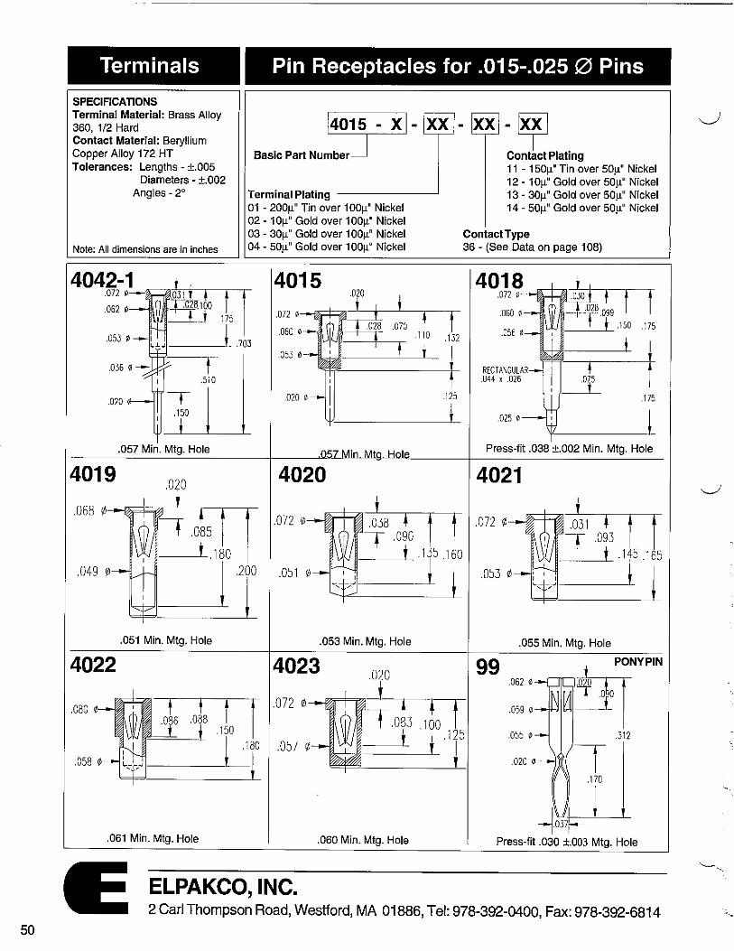
Terminals Pin Receptacles for .015--.025 0 Pins
SPECIFICATIONS Terminal Material: Brass Alloy 360, 1/2 Hard Contact Material: Beryllium Copper Alloy 172 HT Tolerances: Lengths - ±.005
Diameters - ±.002 Angles -2°
~-Basic Part Number J
Terminal Plating
-~ Contact Plating 11 - 150µ" Tin over 50µ" Nickel 12 - 1 0µ" Gold over 50µ" Nickel 13 - 30µ" Gold over 50µ" Nickel 14 - 50µ" Gold over 50µ" Nickel 01 - 200µ" Tin over 100µ" Nickel
02 - 1 0µ" Gold over 100µ" Nickel 03 - 30µ" Gold over 100µ" Nickel 04 - 50µ" Gold over 100µ" Nickel
Contact Type Note: All dimensions are in inches
4042■■1 .072 ¢--
"ii J.Hf'"r'-'-.h
.062 ¢ .175
---~! .703
t .510
.020 T .150
.057 Min. Mtg. Hole
4019 .020
+ .085
-~t .180 .049 !/J ~T
.051 Min. Mtg. Hole
4022
.080 0 f ' t l .086 .088 __t I .150 !
! .180
i
.061 Min. Mtg. Hole
36 - (See Data on page 108)
4015 .020
.on 0--t~~:=:==r-~T- r -----1--"-'02=8 ,070 .060 0 .110 .132
.053 0
j .125
t
4020
.072
.051 r/J
.053 Min. Mtg. Hole
4023 .020
.0 72 r!J ...-.1%~~-....,_J -.-----ii-r t .oL .1bo f
_ _,_j I T .05 7 (/J
.060 Min. Mtg. Hole
4018 .072 0
.060 ~
RECTANGULAR .044 K .026
.025 0
Press-fit .038 ±.002 Min. Mtg. Hole
4021
.055 Min. Mtg. Hole
99 .062 0
.059 0
.055 0
.020 0
~NYPIN
~ _ _1_i__.o o I .312
ELPAKCO, INC. 2 Carl Thompson Road, Westford, MA 01886, Tel: 978-392-0400, Fax: 978-392-6814

Terminals Pin Receptacles for .015-.025 0 Pins
SPECIFICATIONS Terminal Material: Brass Alloy 360, 1/2 Hard Contact Material: Beryllium Copper Alloy 172 HT Tolerances: Lengths - ±.005
Diameters - ±.002 Angles- 2°
Note: All dimensions are in inches
4025
l4oj - xl-easic Part Number
Terminal Plating 01 - 200µ" Tin over 100µ" Nickel 02 - 10µ" Gold over 100µ" Nickel 03 - 30µ" Gold over 100µ" Nickel 04 - 50µ" Gold over 100µ" Nickel
4026
.on 0--l!~~=::±=1~nT .059 ~ KNURL
.053 ¢
.057 Min. Mtg. Hole .057 Min. Mtg. Hole
4028 4275-1
.072 ¢1.031 .060 ¢ .028.100 .162 .20.3
.053 ¢ ~ ,, j i .053 ¢
.1 25
·¥ Contact Plating 11 - 150µ" Tin over 50µ" Nickel 12 - 1 Oµ" Gold over 50µ" Nickel 13 - 30µ" Gold over 50µ" Nickel 14 - 50µ" Gold over 50µ" Nickel
Contact Type 36 - 45 - (See Data on page 108-110)
4027
.072 ¢----.t?lf9=~ ~__,___
.060 ¢
.053 0
.060 0
.D53 0
.033 0
.045 0
.057 Min. Mtg. Hole
.043 J_ .127
'1-"'--------'---t .012 SLOT ----l 1-1 .057 Min. Mtg. Hole .057 Min. Mtg. Hole .038-.040 Hole Prior to Soldering
4031 4275-2 4033
.053 0 .053 0-
020 ¢ .020 ·--{ .275
.022 or .057 Mtg. Hole .057 Min. Mtg. Hole
ELPAKCO, INC. 2 Carl Thompson Road, Westford, MA 01886, Tel: 978-392-0400, Fax: 978-392-6814
51

52
Terminals Pin Receptacles for .015-.025 0 Pins
SPECIFICATIONS Terminal Material: Brass Alloy 360, 1/2 Hard Contact Material: Beryllium Copper Alloy 172 HT Tolerances: Lengths - ±.005
Diameters - ±.002 Angles-2°
Note: All dimensions are in inches
4046 .056 0---
.062 0 BARB
.053 0
.059 Min. Mtg. Hole
~-Basic Part Number J
Terminal Plating -----~ 01 - 200µ" Tin over 100µ" Nickel 02 - 1 0µ" Gold over 100µ" Nickel 03 - 30µ" Gold over 1 00µ" Nickel 04 - 50µ" Gold over 100µ" Nickel
4047 .056 0
.059 ¢ BARB
.057 Min. Mtg. Hole
4280 I- C -j R .062
T A
l_ I
---!043 ~f-S!CIION B - B
I
r s·=1J_ .020
T
~ I I 11--.os4 -J B Lt-.060
45 ' X .005
SECTION A - A
R .042
RIGHT ANGLE SMT RECEPTACLE
Right Angle SMT Receptacle
P/N A B C 4280-1 .157 .125 .110 4280-2 .115 .100 .080 4280-3 .100 .100 .080
ELPAKCO, INC.
PCB
-~ Contact Plating 11 - 150µ" Tin over 50µ" Nickel 12 - 10µ" Gold over 50µ" Nickel 13 - 30µ" Gold over 50µ" Nickel 14 - 50µ" Gold over 50µ" Nickel
ContactType 36 - (See Data on page 108)
4048
.075 .083 .094 .056 I/J
.059 0 BARB
.030 'I! HOLE
.046 I/!
__J_ t t .145
L,J i T .057 Min. Mtg. Hole
98 .062 '/J
.059 I/! BARB .055 ~
.125
l
POLOPIN
.020 I/! li}' .057 Min. Mtg. Hole
4278
.058 it, BARB
.043 !/! HOLE
.020 it,
.057 Min. Mtg. Hole
2 Carl Thompson Road, Westford, MA 01886, Tel: 978-392-0400, Fax: 978-392-6814

Terminals Pin Receptacles for .015-.025 0 Pins
SPECIFICATIONS Terminal Material: Brass Alloy 360, 1/2 Hard Contact Material: Beryllium Copper Alloy 172 HT Tolerances: Lengths - ±.005
Diameters - ±.002 Angles -2°
l4o-j" xl-easic Part Number
Terminal Plating
-, Contact Plating 11 - 150µ" Tin over 50µ" Nickel 12 - 10µ" Gold over 50µ" Nickel 13 - 30µ" Gold over 50µ" Nickel 14 - 50µ" Gold over 50µ" Nickel 01 - 200µ" Tin over 100µ" Nickel
02 - 10µ" Gold over 100µ" Nickel 03 - 30µ" Gold over 100µ" Nickel 04 - 50µ" Gold over 100µ" Nickel
Contact Type Note: All dimensions are in inches
4034
.190 P/N 4034-1
.053 ¢ 4034-2 4034-3 4034-4 4034-5
A
~";____,__J 4034-6 4034-7
A .210 .410 .455 .560 .635 .700
1.215
36 - (See Data on page 108)
4041 .072 1/) ----ie,;;::r:::½I
.060 1/1
.053 ¢ .350
I I
.1 24
i .057 Min. Mtg. Hole .057 Min. Mtg. Hole
4042
.057 Min. Mtg. Hole
4044
I .835
.053 ¢-
.500 .032 ¢ ~
.050 0 ~--_,.03_5--+----~
.020 "'~------·1~65_
.057 Min. Mtg. Hole
4043 .060 1/,-
A
o:~:,{ __ ____._1
.057 Min. Mtg. Hole
4045 .012 ¢ ---11.::±z;,a-iof~o --:!f~7 -! ---.:--i-r
.059 ¢ KNURL r1-----'-- . I 46 .292 I I I
"' • l-.J~j J, .033 1-m _j_
.051 0 , .059
--------'-.018 ¢ 11J= ______ .12~6
.057 Min. Mtg. Hole
ELPAKCO, INC.
P/N A 4043-1 .236 4043-2 .315 4043-3 .402 4043-4 .472 4043-5 .594 4043-6 .699
P/N A 4045-1 .841 4045-2 1.141
2 Carl Thompson Road, Westford, MA 01886, Tel: 978-392-0400, Fax: 978-392-6814 53

54
Terminals Wire Wrap Receptacles for .015-.025 0
SPECIFICATIONS Terminal Material: Brass Alloy 360, 1/2 Hard ~-
Basic Part Number J Contact Material: Beryllium Copper Alloy 172 HT Tolerances: Lengths - ±.005
Diameters - ±.002 Angles- 2° Terminal Plating -----~
01 - 200µ" Tin over 100µ" Nickel 02 - 1 0µ" Gold over 100µ" Nickel 03 - 30µ" Gold over 100µ" Nickel
Note: All dimensions are in inches 04 - 50µ" Gold over 100µ" Nickel
4103 .072 ¢--ti~ ki ♦ -♦-1.020_ ~
~~.100 --TT .162 - t 1
.200
I .260
.055 Min. Mtg. Hole
4106 1.020_ ~
. 062 ¢----i-,1;:1.rm * -i-.058 ¢ KNURL -~.lOO
=-T -r .1l2200
I .260
.055 Min. Mtg. Hole
4104
.055 Mtg. Hole
4107
.055 Min. Mtg. Hole
4109 -~ ~ t
4110 -~. f
.072 0 f
.072 ¢ -~B.10~ .060 ¢ ♦ t,162 .060 0
-~B.100 • 7" t .162
l .193
t I
.260
.057 Min. Mtg. Hole .057 Min. Mtg. Hole
ELPAKCO, INC.
-~ Contact Plating 11 - 150µ" Tin over 50µ" Nickel 12 - 1 0µ" Gold over 50µ" Nickel 13 - 30µ" Gold over 50µ" Nickel 14 - 50µ" Gold over 50µ" Nickel
ContactType 36 - 45 - (See Data on pages 108-110)
.360
.193
t .360
4105
4108 .062 0
.058 el KNURL
.500
.055 Min. Mtg. Hole
Lo20_~ .0 1 .rJ.o!, .100 .162 .
-T t t .200 ,
I .500
.055 Min. Mtg. Hole
4111 -~. t .072 0 t .060 0 -~8100 ♦ t,162
i ,1g3
t .500
2 Carl Thompson Road, Westford, MA 01886, Tel: 978-392-0400, Fax: 978-392-6814
I '-.._.,/
-

,_,,,.,--..
Terminals Pin Receptacles for .025-.032 0 Pins & .025 Sq. Post
SPECIFICATIONS Terminal Material: Brass Alloy 360, 1/2 Hard Contact Material: Beryllium Copper Alloy 172 HT Tolerances: Lengths - ±.005
Diameters - ±.002 Angles- 2°
Note: All dimensions are in inches
4049 .014
.233 .060 0
.063 Min. Mtg. Hole
4052
.020 0
.067 Min. Mtg. Hole
4055
.094 0
t .125
~ Swage Mount in .060 Hole
~-Basic Part Number J
Terminal Plating -------' 01 - 200µ" Tin over 100µ" Nickel 02 - 10µ" Gold over 100µ" Nickel 03 - 30µ" Gold over 100µ" Nickel 04 - 50µ" Gold over 100µ" Nickel
4050 .093 0
030 t t I t.113 I ~ 110 . I .250
LiJ 1-----'-- I .071 Min. Mtg. Hole
.020 ~
.067 Min. Mtg. Hole
P/N BoardThk 4055-1 .031 4055-2 .062 4055-3 .094 4055-4 .125
.128
I
A .051 .082 .113 .145
ELPAKCO, INC.
-~ Contact Plating 11 - 150µ" Tin over 50µ" Nickel 12 - 1 Oµ" Gold over 50µ" Nickel 13 - 30µ" Gold over 50µ" Nickel 14 - 50µ" Gold over 50µ" Nickel
ContactType 54 - {See Data on page 111)
4051 .090 e---~1-&f:1~
t -t I 2t l?l-_____,_ , ,, I
.073 ¢
.076 Min. Mtg. Hole
4054 .oss ¢ ~m;:::g1~_03;;-1 -t-niT
.069 ¢ !3, --'IC--"·0~28.1 28
i .220
' ' I .062 ~- l---)1------'- A
T
.020 ~ .128
P/N A 4054-1 .353 4054-2 .333 4054-3 .413
.067 Min. Mtg. Hole
2 Carl Thompson Road, Westford, MA 01886, Tel: 978-392-0400, Fax: 978-392-6814 55

56
Terminals Pin Receptacles for .025-.032 0 Pins & .025 Square Pins
SPECIFICATIONS Terminal Material: Brass Alloy 360, 1/2 Hard Contact Material: Beryllium Copper Alloy 172 HT Tolerances: Lengths - ±.005
~-Basic Part Number J
Diameters - ±.002 Angles -2° Terminal Plating -----~
01 - 200µ" Tin over 100µ" Nickel 02 - 1 0µ" Gold over 100µ" Nickel 03 - 30µ" Gold over 100µ" Nickel
Note: All dimensions are in inches 04 - 50µ" Gold over 1 00µ" Nickel
4056 4282 .os5 1/J--flrr~ '=::::rr:-r,-r .098 0,--~=ajj~-~--,-..
.070 1/J KNURL .081 ~
.061 '/J .073 0
.210
_J .067 Min. Mtg. Hole Press-fit in .078 Min. Mtg. Hole
4115 .064 0---t1;;;;i;;;;;!I b_ t J f I
.070 '/J KNURL . ♦ .040 .093 I -----+-t ______.t .150 .175
i I .025 SQUARE
P/N A 4115-1 .370
4115-2 .430
f~j .067 Min. Mtg. Hole
ELPAKCO, INC.
-~ contact Plating 11 - 150µ" Tin over 50µ" Nickel 12 - 1 0µ" Gold over 50µ" Nickel 13 - 30µ" Gold over 50µ" Nickel 14 - 50µ" Gold over 50µ" Nickel
Contact Type 54 - {See Data on page 111)
411 Z2s ~--w-~ I : • f j .246 .280
.060 ~
.052 ~
.100 ~ - ,-r-,.....,.,
UJ~ ~ .160
1 .570
.025 SQUARE ! .057 Min. Mtg. Hole
4116 .085 0•---,~-.rnik±-n--r
~-ti I
----2--'-r ~, .510
.079 Min. Mtg. Hole
2 Carl Thompson Road, Westford, MA 01886, Tel: 978-392-0400, Fax: 978-392-6814

Terminals SPECIFICATIONS Terminal Material: Brass Alloy 360, 1/2 Hard Contact Material: Beryllium Copper Alloy "172 HT Tolerances: Lengths - ±.005
Diameters - ±.002 Angles - 2°
Note: All dimensions are in inches
4057
.086 .165
.061 Min. Mtg. Hole
4061
.063 ~
.025 0
.067 Min. Mtg. Hole
Pin Receptacles for .025-.032 0 Pins & .025 Square Pins
~-Basic Part Numberj
Terminal Plating
-~ Contact Plating 11 - 150µ" Tin over 50µ" Nickel 12 - 1 Oµ" Gold over 50µ" Nickel 13 - 30µ" Gold over 50µ" Nickel 14 - 50µ" Gold over 50µ" Nickel 01 - 200µ" Tin over 100µ" Nickel
02 - 1 Oµ" Gold over 100µ" Nickel 03 - 30µ" Gold over 100µ" Nickel 04 - 50µ" Gold over 100µ" Nickel
Contact Type 48 - (See Data on page 111)
4058 .016
4059
.200
i
.065 ¢---ii;;:;;;l::::;jll --'-...L__-l--~--
.072 ¢
.064 ¢
.059 0
.146 I , ___ .,___,__ l .165
I .125
.072 0 - ;;;;;i;;;;~ .030 ,. _ _,__.0_31 .092
' .064 0
.D59 ~
.024 0 ~-------'-l jL 135
.061 Min. Mtg. Hole .061 Min. Mtg. Hole
4271
.086 .165
.185
I .057 rJ;
.200
,1-------------1 l .125
Hex Press-fit in .061 Min. Mtg. Hole
ELPAKCO, INC. 2 Carl Thompson Road, Westford, MA 01886, Tel: 978-392-0400, Fax: 978-392-6814
57

58
Terminals Pin Receptacles for .032-.047 0 Pins
SPECIFICATIONS Terminal Material: Brass Alloy 360, 1/2 Hard Contact Material: Beryllium Copper Alloy 172 HT Tolerances: Lengths - ±.005
Diameters - ±.002 Angles- 2°
Note: All dimensions are in inches
4063 .094 ,
.m~
.091 ,
.040 I
.196
A
1-.167
l
~-Basic Part Numberj
Terminal Plating 01 - 200µ" Tin over 100µ" Nickel 02 - 1 0µ" Gold over 100µ" Nickel 03 - 30µ" Gold over 100µ" Nickel 04 - 50µ" Gold over 100µ" Nickel
P/N Board Thk 4063-1 .031 4063-2 .062 4063-3 .094 4063-4 .125 4063-5 .188
A .062 .094 .125 .156 .219
Swage Mount in .094 Min. Mtg. Hole
4065
.078 ¢
.030 0
.4067
' ' ' I I I
' '
.220
I,,.-=-: ,.-,..JI-------'-
.082 Min. Mtg. Hole
.018
-r,;o t 8
! .075 Min. Mtg. Hole
.250
.125
A
l
.120 ~1-~r---;~..,...-t-----.-----.---,--.065 ~- ~ir-+-,&1'1L~J.,..
I
L.-_'),-----~i T .092 ~
.082 ~
.030 ~ .145
I .089 Min. Mtg. Hole
P/N B A 4067-1 .206 .180 4067-2 .226 .200 4067-3 .270 .241 4067-4 .280 .250
ELPAKCO, INC.
-~ Contact Plating 11 - 150µ" Tin over 50µ" Nickel 12 - 1 0µ" Gold over 50µ" Nickel 13 - 30µ" Gold over 50µ" Nickel 14 - 50µ" Gold over 50µ" Nickel
ContactType 42 - (See Data on page 108)
4064 ooo,
4071
.071 ~
17--,~--I- .180
1------''- .206
Hex Press-fit in .076 Min. Mtg. Hole
4072
.072 ¢ -
.075 Min. Mtg. Hole
2 Carl Thompson Road, Westford, MA 01886, Tel: 978-392-04001 Fax: 978-392-6814

Terminals Pin Receptacles for .032-.047 0 Pins
SPECIACA TIONS Terminal Material: Brass Alloy 360, 1/2 Hard Contact Material: Beryllium Copper Alloy 172 HT Tolerances: Lengths - ±.005
Diameters - ±.002 Angles- 2°
Note: All dimensions are in inches
4073
~-Basic Part Number J
Terminal Plating - - ----' 01 - 200µ" Tin over 100µ" Nickel 02 - 1 Oµ • Gold over 100µ" Nickel 03 - 30µ" Gold over 100µ" Nickel 04 - 50µ" Gold over 100µ" Nickel
4074 .092 0
__L .132 I
.080 .030
l t t .081 0 KNURL .195
.1W 0-~~~ T I o : .2 ,20 .2513 I .140
.078 Min. Mtg. Hole
4076
.120 ¢
.205
l----'--1 T .089 Min. Mtg. Hole
4079
.093 0 KNURL
.080 0
"'""-----r--~.190 I : T I .2so
l I I ' ~-t-J-~ I ...... ,,.,,
I
.089 Min. Mtg. Hole
.088 ~
: I : ~ 1.-+-;,I 1----~ ...... ..,. ....
.091 Min. Mtg. Hole
4077 .020
.036
TT .uo t
.195
, ____ i~.236
.087 Min. Mtg. Hole
4080
.093 0 KNURL
.082 0
.040 ~
.060 0
.083
=i= .089 Min. Mtg. Hole
.190 I .240
j .103
t
ELPAKCO, INC.
-~ Contact Plating 11 - 150µ" Tin over 50µ" Nickel 12 - 10µ" Gold over 50µ" Nickel 13 - 30µ" Gold over 50µ" Nickel 14 - 50µ" Gold over 50µ" Nickel
Contact Type 42 - (See Data on page 108)
4075 .031
f .130
♦ .200
1----'-l'f .087 Min. Mtg. Hole
4078
.063 0 HOLE --j
.020
.036
n .130
t
f--.087 Min. Mtg. Hole
4081 .015
.093 0 KNURL
.080 0
.195
i-- .064 0 HOLE
.089 Min. Mtg. Hole
.236
!
.250
2 Carl Thompson Road, Westford, MA 01886, Tel: 978-392-0400, Fax: 978-392-6814 · 59

60
Terminals Pin Receptacles for .032-.047 0 Pins SPECIFICATIONS Terminal Material: Brass Alloy 360, 1/2 Hard Contact Material: Beryllium Copper Alloy 172 HT Tolerances: Lengths - ±.005
Diameters - ±.002 Angles-2°
Note: All dimensions are in inches
4082
~-Basic Part Number J
Terminal Plating -----~ 01 - 200µ" Tin over 100µ" Nickel 02 - 1 0µ" Gold over 100µ" Nickel 03 - 30µ" Gold over 100µ" Nickel 04 - 50µ" Gold over 100µ" Nickel
4083 .018
11
°' 4TT 1'0,1---♦'- .250
.090 </J
! .,~5
==1=='1__l_ .072 </J .206
.063 ¢ HOLE --l 1---.102 Min. Mtg. Hole
4118
.083 Min. Mtg. Hole
.360
t i
.075 Min. Mtg. Hole (Knock-out Bottom)
.083 Min. Mtg. Hole
ELPAKCO, INC.
-~ Contact Plating 11 - 150µ" Tin over 50µ" Nickel 12 - 10µ" Gold over 50µ" Nickel 13 - 30µ" Gold over 50µ" Nickel 14 - 50µ" Gold over 50µ" Nickel
Contact Type 42 - (See Data on page 108)
2006 .090 ¢
.082 '/J KNURi: .030
.180 .206
! .070 0
CHAMFER .010 X 45'
Press-fit in .078 Mtg. Hole
f .075 .130 t f .205
u Ir .510
l .087 Min. Mtg. Hole
2 Carl Thompson Road, Westford, MA 01886, Tel: 978-392-0400, Fax: 978-392-6814
'---. -~

Terminals
SPECIFICATIONS Terminal Material: Brass Alloy 360, 1/2 Hard Contact Material: Beryllium Copper Alloy 172 HT Tolerances: Lengths - ±.005
Diameters - ±.002 Angles-2°
Note: All dimensions are in inches
4085
Pin Receptacles for .040-.060 0 Pins
~-Basic Part Numberj
Terminal Plating 01 - 200µ" Tin over 100µ" Nickel 02 - 1 0µ" Gold over 100µ" Nickel 03 - 30µ" Gold over 100µ" Nickel 04 - 50µ" Gold over 100µ" Nickel
4086
Contact Type
-~ Contact Plating 11 - 150µ" Tin over 50µ" Nickel 12 - 1 0µ" Gold over 50µ" Nickel 13 - 30µ" Gold over 50µ" Nickel 14 - 50µ" Gold over 50µ" Nickel
41 - 43 (#4084/#4276) - (See Data on pages 109-112)
4087 .120 0~Fl~,f¼r_:1-t_x-~_t--r-.---,.031 .105 ¢
.102 0
4088
.125 0
.100 0
.076 .160
.106 Min. Mtg. Hole
.070
-,- .160
.205 .120 0-.105 ¢
.270 . 109 ¢
I .102 0
.120
.031
.076 .160 .205
i ' ' ~:-;7
.106 Min. Mtg. Hole
.118 0
.270
l .100 0
050
-,- .160
l .255 .290 .. ~1 I
.102 Min. Mtg. Hole
.102 Min. Mtg. Hole Pin Receptacles for .040-.050 0 Pins
4084 .016 I
4276
.100 0 : .260 .290
l.j:,''iI ---~l .088 ¢
.102 Min. Mtg. Hole Quintagonal Press-fit in .103 PTH
ELPAKCO, INC. 2 Carl Thompson Road, Westford, MA 01886, Tel: 978-392-0400, Fax: 978-392-6814
61

62
Terminals Pin Receptacles for .045-.067 0 Pins
SPECIFICATIONS Terminal Material: Brass Alloy 360, 1/2 Hard Contact Material: Beryllium Copper Alloy 172 HT Tolerances: Lengths - ±.005
Diameters - ±.002 Angles -2°
Note: All dimensions are in inches
4089
~-Basic Part Num~er J
Terminal Plating -------01 - 200µ" Tin over 100µ" Nickel 02 - 1 0µ" Gold over 100µ" Nickel 03 - 30µ" Gold over 100µ" Nickel 04 - 50µ" Gold over 100µ" Nickel
4090
.1w,~F~~~
T ·1i0 .Jo .2!3
.136 0
.112 0 KNURe
.015
.037
.098 0
.102 Min. Mtg. Hole
4092
.100 ~
.088 ~ HOLE--!
.102 Min. Mtg. Hole
.050 .134
.088 o HOLE---j ~-
.108 Mtg. Hole
4093 .1 18 ~~~Rl[J.O@Jlr-i1 1T .105 0
.1 09 0
.040 0
.076 .140
.106 Min. Mtg. Hole
.200 .270
.1 25
t
ELPAKCO, INC.
-~ Contact Plating 11 - 150µ" Tin over 50µ" Nickel 12 - 1 Oµ" Gold over 50µ" Nickel 13 - 30µ" Gold over 50µ" Nickel 14 - 50µ" Gold over 50µ" Nickel
ContactType 41 - (See Data on page 109)
4091
.1 18 0--tl~:l=~~
-r .1~4 I i .225
Bl-----'-- ! .100 0 I
I
.088 0 HOLE __j .102 Min. Mtg. Hole
4094 .110 ¢--lJC~~---=~f ---;1~111r
0 .110 .107 0
.255 .290
.096 0 I • l L-,1-) 1----__L_
.102 Min. Mtg. Hole
2 Carl Thompson Road, Westford, MA 01886, Tel: 978-392-0400, Fax: 978-392-6814

-.
Terminals Pin Receptacles for .065-.082 0 Pins
SPECIFICATIONS Terminal Material: Brass Alloy 360, 1/2 Hard Contact Material: Beryllium Copper Alloy 172 HT Tolerances: Lengths - ±.005
Diameters - ±.002 Angles -2°
Note: All dimensions are in inches
4095 .025
'
~-Basic Part Nu~J
Terminal Plating -----~ 01 - 200µ" Tin over 100µ" Nickel 02 - 10µ" Gold over 100µ" Nickel 03 - 30µ" Gold over 100µ" Nickel 04 - 50µ" Gold over 100µ" Nickel
4096 ,143 ¢---{!i;=j~~-'---i-.---r
-l .Oil
.157 ,166 • T .ioo .160
I .340
.1\B ~ .142 • lJJ i 'j' .120 Min. Mtg. Hole .144 Min. Mtg. Hole
4098 4099
I 1
.156 ~ .031 .080
.147 0 .018
.150 .155 .1 95
I .240 .223
I .137 ~ j
.130 Min. Mtg. Hole .142 Min. Mtg. Hole
4102 144'
P/N BoardThk A 4102-1 .031 .062
.440 4102-2 .062 .094 4102-3 .094 .125 4102-4 .125 .156 4102-5 .188 .219
.09) •
.083 .10}
Swage Mount in .096 Mtg. Hole
ELPAKCO, INC.
-~ Contact Plating 11 - 150µ" Tin over 50µ" Nickel 12 - 1 Oµ" Gold over 50µ" Nickel 13 - 30µ" Gold over 50µ" Nickel 14 - 50µ" Gold over 50µ" Nickel
ContactType 40 - (See Data on page 109)
4097
.156 0
4100
.OJ2
T .160
.260
I
.159 Min. Mtg. Hole
.026 .165 1 ~
.120
.136 , I
.142 Min. Mtg. Hole
4101
.309
.150
255
I
.144 I
ITT j 5
.440
.063 Min. Mtg. Hole
2 Carl Thompson Road, Westford, MA 01886, Tel: 978-392-0400, Fax: 978-392-6814 63

64
Terminals
SPECIFICATIONS Terminal Material: Brass Alloy 360, 1/2 Hard Tolerances: Lengths - ±.005
Diameters - ±.002 Angles-2°
Note: All dimensions are in inches
4121 t .016 1/J
.118
.032 1/J
.083 .036 '/J I
I .118
t .034 Min. Mtg. Hole
4124
.020 ¢
Surface Mount
4126 t
.045 '/J
.020 .100
t t t t
A
! .057-.059 Min. Mtg. Hole
Printed Circuit Pins
1412] - xl-lxlxl Basic Part Number
4122 .018 rt,
I .015 .1 5
.020 .040 rt,
.085 .030 r/J l .018 rt,
.125
.033 Min. Mtg. Hole
4125 t
.045 ¢
.020 .125
t t t t
.020 0 .170
l .024 Min. Mtg. Hole
P/N A 4126-1 .250 4126-2 .425 4126-3 .525 4126-4 .550 4126-5 .930
Pin Plating 01 - 200µ" Tin over 100µ" Nickel 02 - 1 0µ" Gold over 100µ" Nickel 03 - 30µ" Gold over 100µ" Nickel 04 - 50µ" Gold over 100µ" Nickel
i .051
.010
.215 .020 r/J
j .031 Min. Mtg. Hole
4127
.072 r/J-
.173
.053 r/J I .057-.059 Min. Mtg. Hole
1066 .016 ¢
.118
hl .0315 I .036 0-'--i--'>·-~: - _
I
.032 0
I .11 s
.015 0 I ~
+-____.__-.035 Min. Mtg. Hole
ELPAKCO, INC. 2 Carl Thompson Road, Westford, MA 01886, Tel: 978-392-0400, Fax: 978-392-6814

Terminals
SPECIFICATIONS Terminal Material: Brass Alloy 360, 1/2 Hard Tolerances: Lengths - ±.005
Diameters - ±.002 Angles -2°
Note: All dimensions are in inches
.049 0
.078 0
.017 ¢
.052 Min. Mtg. Hole
4132
.040 (/J-
.017 ¢
.035 Min. Mtg. Hole
4134 .019 SQUARE
.018 ~
PIN A 4134-1 .303 4134-2 .200
.022 Min. Mtg. Hole
t A
t .030
t .155
'
Printed Circuit Pins
~-~ Basic Part Nu=r- I
P/N A D 4129-1 .051 .035 4129-2 .082 .062 4129-3 .113 .062 4129-4 .145 .062
Ii
062 0
.020
,~ .035 I y t .113
' ! I ~ I .025
' t I I '
~~! 250
I j .043 Min. Mtg. Hole
4136 .020
.026 Min. Mtg. Hole
Pin Plating 01 - 200µ" Tin over 100µ" Nickel 02 - 1 0µ" Gold over 100µ" Nickel 03 - 30µ" Gold over 100µ" Nickel 04 - 50µ" Gold over 100µ" Nickel
4130
.040 ! i
.051
.050 ¢ -~
.050 f ; • .op
.040 Min. Mtg. Hole
4135
' f---r----1--· 02~8 f .102
.053 (/J -
Lf .018 f/J
.1 56
i .057 Min. Mtg. Hole
4136-1
.023 r/J
.028 r/J
.045 r/J
.020
.1 0
i .026 Min. Mtg. Hole
ELPAKCO, INC. 2 Carl Thompson Road, Westford, MA 01886, Tel: 978-392-0400, Fax: 978-392-6814
65

I
66
Terminals
SPECIFICATIONS Terminal Material: Brass Alloy 360, 1/2 Hard Contact Material: Beryllium Copper Alloy 172 HT Tolerances: Lengths - ±.005
Diameters - ±.002 Angles-2°
Note: All dimensions are in inches
4290
Press-fit in .138 Min. Mtg. Hole
4292 .156 I
.122
_l .385
I I I 1.--t--,J 1--~~ ' / " / 'V
Swage Mount in .094 Mtg. Hole
Pin Receptacles for .065-.082 0 Pins
Terminal Plating -----~ 01 - 200µ'' Tin over 100µ" Nickel 02-10µ" Gold over 100µ" Nickel 03 - 30µ" Gold over 100µ" Nickel 04 - 50µ" Gold over 100µ" Nickel
4291
.168 • .105
I
.142 f
I .415
_J .360
I I I l.-r·::-1
.144 Min. Mtg. Hole
.445
P/N BoardThk A 4292-1 .062 .094 4292-2 .094 .125 4292-3 .125 .156
Contact Plating 11 - 150µ" Tin over 50µ" Nickel 12-10µ" Gold over 50µ" Nickel 13 - 30µ" Gold over 50µ" Nickel 14 - 50µ" Gold over 50µ" Nickel
Contact Type 40 - 55 (See Data on page 109 & 112}
4289 .156 f
.650
.600
.146 f .740
.028
.090 .030
142 f BARB-·r--~.....,
.125 ~ -~~;,-==i=~----_j_
Press-fit in .136 Min. Mtg. Hole
ELPAKCO, INC. 2 Carl Thompson Road, Westford, MA 01886, Tel: 978-392-0400, Fax: 978-392-6814
J -
·.,__

r
Terminals
SPECIFICATIONS Terminal Material: Brass Alloy 360, 1/2 Hard Tolerances: Lengths - ±.005
Diameters - ±.002 Angles- 2°
Note: All dimensions are in inches
4145
.057 Min. Mtg. Hole
4148 t
.142
.072
.057 Min. Mtg. Hole
Printed Circuit Pins
l414j - xl-ljl Basic Part Number
4146 ~
,020 .125
------L _•__J~: ¥~1 I t
.057 Min. Mtg. Hole
4149 .018 0
.057 Min. Mtg. Hole
4139-1 .016·026
044 0 KNURl:
.038 1/J
I
I
• . 125
t
t .166
i
Pin Plating 01 - 200µ" Tin over 100µ" Nickel 02 - 1 0µ" Gold over 100µ" Nickel 03 - 30µ" Gold over 100µ" Nickel 04 - 50µ" Gold over 100µ" Nickel
4147
.057 Min. Mtg. Hole
.053 0
.020 0--I
I .295 .053 1/J
.020 rt, iLl .115
i .040 Min. Mtg. Hole .057 Min. Mtg. Hole
ELPAKCO, INC.
.168
l
2 Carl Thompson Road, Westford, MA 01886, Tel: 978-392-0400, Fax: 978-392-6814 67

68
Terminals
SPECIFICATIONS Terminal Material: Brass Alloy 360, 1/2 Hard Tolerances: Lengths - ±.005
Diameters - ±.002 Angles -2°
Note: All dimensions are in inches
.125 .018 ¢ t .057 Min. Mtg. Hole
4156 .021 1/J .095
.0~8 f f ~ B
.018 1/J --+ .155
.057 Min. Mtg. Hole
4158 .018 ¢
.072 0
.060 ¢ KNURL .053 0 .034 0
.024 0
.157
o!i I I I t .028 f 120
I or f
.126
.057 Min. Mtg. Hole
Printed Circuit Pins
~~~ Basic Part Num~ I
P/N A 4153-1 .210 4153-2 .335 4153-3 .585 4153-4 .835
P/N K S 4156-1 .030 .190 4156-2 .040 .430
4159,025
.072 ¢
.063 0
.018 0
.057 Min. Mtg. Hole
Pin Plating 01 - 200µ" Tin over 100µ" Nickel 02 - 1 0µ" Gold over 100µ" Nickel 03 - 30µ" Gold over 100µ" Nickel 04 - 50µ" Gold over 100µ" Nickel
4155 .021 0--m- ., fs
.on•-~~ .028
t t .053 0
~ .021 0 .1 15
t .057 Min. Mtg. Hole
4157 .018 ¢
.072 0
.157
.060 0 KNURL_J•--=:=jt':]!~ .l lO .053 ¢
.225
.057 Min. Mtg. Hole
4160 .018 0
.072 ¢
.063 0
.060 0 .053 0
.018 ¢
'rf ti 252
~ .154
l .057 Min. Mtg. Hole
ELPAKCO, INC. 2 Carl Thompson Road, Westford, MA 01886, Tel: 978-392-0400, Fax: 978-392-6814

r'
Terminals
SPECIFICATIONS Terminal Material: Brass Alloy 360, 1/2 Hard Tolerances: Lengths - ±.005
Diameters - ±.002 Angles- 2°
Note: All dimensions are in inches
4161.0250 .047 0
.072 0
.060 0
.053 0
.018 0
.057 Min. Mtg. Hole
4163_018 0 l
.072
t
1[___.__1 .057 Min. Mtg. Hole
4166
.054
.057 Min. Mtg. Hole
.118
i .484
l .146
t .118
Printed Circuit Pins
~-~ Basic Part Nu::T. I
.072 0
.060 0
.053 0
.018 0
.057 Min. Mtg. Hole
P/N A 4163-1 .210 4163-2 .410
4167
.057 Min. Mtg. Hole
Pin Plating 01 - 200µ" Tin over 100µ" Nickel 02 - 1 Oµ" Gold over 1 00µ" Nickel 03 - 30µ" Gold over 100µ" Nickel 04 - 50µ" Gold over 100µ" Nickel
4164
.018 r/J
.057 Min. Mtg. Hole
4165 .025 ¢
.053 ¢
.018 ¢
.057 Min. Mtg. Hole
4168
.057 Min. Mtg. Hole
ELPAKCO, INC.
t .135
t
2 Carl Thompson Road, Westford, MA 01886, Tel: 978-392-0400, Fax: 978-392-6814 69

70
Terminals
SPECIFICATIONS Terminal Material: Brass Alloy 360, 1 /2 Hard Tolerances: Lengths - ±.005
Diameters - ±.002 Angles -2°
Note: All dimensions are in inches
4169 f .170
.072 0 ! A
t .052 0 .145
t • .021 0 .115 j
.057 Min. Mtg. Hole
4173 .053 0--- f .039 r/J .0{9 .158
.060 ¢~=!=::) o2t1, I t .053 r/J '
.156
t .057 Min. Mtg. Hole
Printed Circuit Pins
l41&j - x 1- lxlxl Basic Part Number
P/N A 4169-1 .052 4169-2 .100 4169-3 .170 4169-4 .460 4169-5 .934
4172 .030 ¢
.018 0-- !
.057 Min. Mtg. Hole
Pin Plating 01 - 200µ" Tin over 100µ" Nickel 02 - 1 0µ" Gold over 100µ" Nickel 03 - 30µ" Gold over 100µ" Nickel 04 - 50µ" Gold over 100µ" Nickel
4170 .030
.072 0
I t I .195
I .QJ~t ! fft1 I .or·T I
.210 .024 ¢ ~
.057 Min. Mtg. Hole
P/N A 4172-1 .417 4172-2 .217
P/N A 4174-1 .121 4174-2 .181
ELPAKCO, INC. 2 Carl Thompson Road, Westford, MA 01886, Tel: 978-392-0400, Fax: 978-392-6814
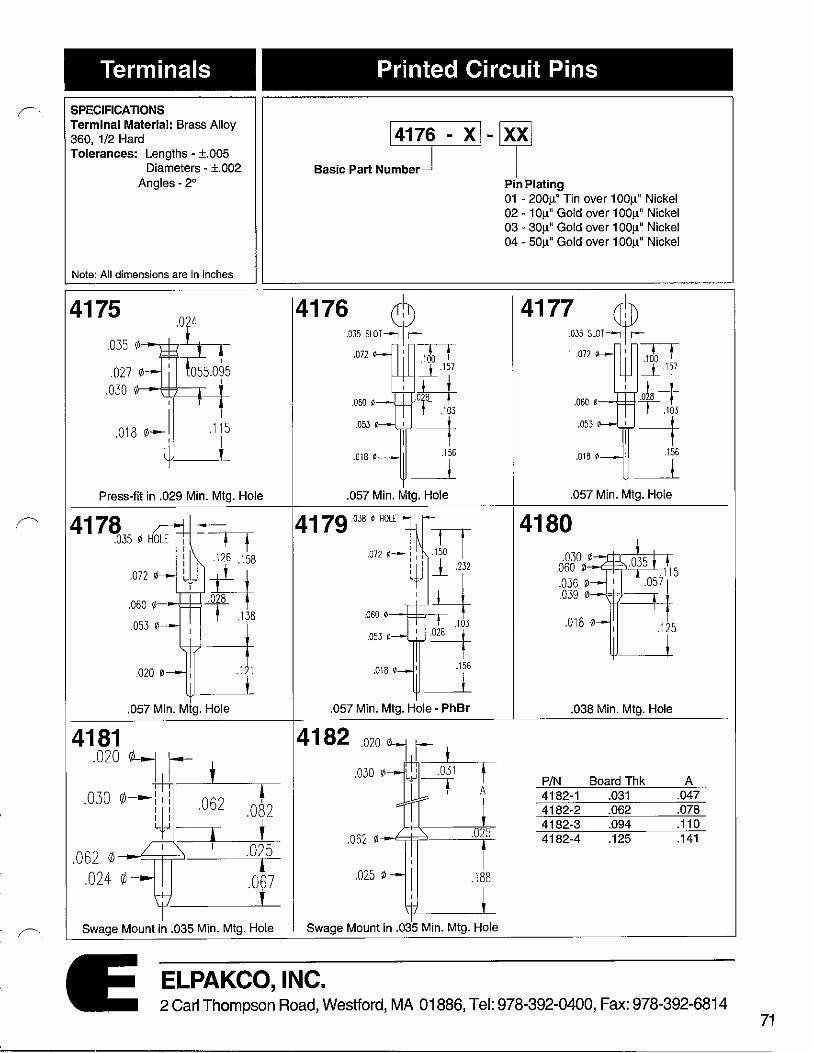
I
r ,
r' I
. r----.
Terminals
SPECIFICATIONS Terminal Material: Brass Alloy 360, 1/2 Hard Tolerances: Lengths - ±.005
Diameters - ±.002 Angles- 2°
Note: All dimensions are in inches
4175 .035 ¢
.024
:o!so1s
.115
t Press-fit in .029 Min. Mtg. Hole
.057 Min. Mtg. Hole
4181 .020 ~ I t
.030 ~ ~ .062 .082
i ' .062 </J .025
.ot7 .024 ¢
t Swage Mount in .035 Min. Mtg. Hole
Printed Circuit Pins
~-~ Basic Part Nu::r- I
41760~ SLOT~t .072 I Tor
_L .157
.H T .103
.053 -+ .018 ¢
.156
t .057 Min. Mtg. Hole
,018 0 I
.057 Min. Mtg. Hole - PhBr
t A
i .062 </J
.025
t .025 ¢ .188
i Swage Mount in .035 Min. Mtg. Hole
Pin Plating 01 - 200µ" Tin over 100µ" Nickel 02 - 1 0µ" Gold over 100µ" Nickel 03 - 30µ" Gold over 100µ" Nickel 04 - 50µ" Gold over 100µ" Nickel
4177,,rn,t · .072 I Tor
_L,157
H 1.103
.053 -+ .016 0 .156
t .057 Min. Mtg. Hole
4180
.038 Min. Mtg. Hole
P/N Board Thk A 4182-1 .031 .047 4182-2 .062 .078 4182-3 .094 .110 4182-4 .125 .141
ELPAKCO, INC. 2 Carl Thompson Road, Westford, MA 01886, Tel: 978-392-0400, Fax: 978-392-6814
71

72
Terminals
SPECIFICATIONS Terminal Material: Brass Alloy 360, 1/2 Hard Tolerances: Lengths - ±.005
Diameters - ±.002 Angles- 2°
Note: All dimensions are in inches
4183 .020 07 r, .031 0-
.050 0 I t
.150
I
Printed Circuit Pins
l41aj - xl-ljl Basic Part Number
P/N 4183-1 4183-2
A .051 .082
Pin Plating 01 - 200µ" Tin over 100µ" Nickel 02 - 1 Oµ" Gold over 100µ" Nickel 03 - 30µ" Gold over 100µ" Nickel 04 - 50µ" Gold over 100µ" Nickel
Swage Mount in .035 Min. Mtg. Hole Swage Mount in .043 Min. Mtg. Hole
4193
P/N A 4184-1 .051 4184-2 .082
.020 .1<'.-0
.1 08
i Swage Mount in .035 Min. Mtg. Hole .057 Min. Mtg. Hole
4199 .040 07 r- 419s .059 ¢
.093 0
.030 0
: I : t : I : .100 : i ___L .125 1.-.,...J-,...J i
.030
ii 1 _240
iLJ .025 0
P/N A 4185-1 .051 4185-2 .082
Swage Mount in .062 Min. Mtg. Hole Swage Mount in .035 Min. Mtg. Hole
ELPAKCO, INC. 2 Carl Thompson Road, Westford, MA 01886, Tel: 978-392-0400, Fax: 978-392-6814

. ('
Terminals
SPECIFICATIONS Terminal Material: Brass Alloy 360, 1/2 Hard
Printed Circuit Pins
Tolerances: Lengths - ±.005 Diameters - ±.002
Angles -2°
l41sj - xl-ljl Basic Part Number
Note: All dimensions are in inches
4186
P/N A 4186-1 .051 4186-2 .082
$wage Mount in .035 Min. Mtg. Hole
4187 .027 011,
.040 0 - t : ,:~035A 1,....,1
I
I . 12s
!
.062 r/J
P/N BoardThk A 4187-1 .031 .051 4187-2 .062 .082 4187-3 .094 .113
Swage Mount in .043 Min. Mtg. Hole
ELPAKCO, INC.
Pin Plating 01 - 200µ" Tin over 100µ" Nickel 02 - 1 Oµ" Gold over 100µ" Nickel 03 - 30µ" Gold over 100µ" Nickel 04 - 50µ" Gold over 100µ" Nickel
4189 .023 ¢7
.047 rt,
.062 (/)-
~ A
J
I --TIT .179 -"" . ~- I
P/N Board Thk A 4189-1 .031 .051 4189-2 .062 .082 4189-3 .094 .113 4189-4 .125 .145
$wage Mount in .052 Min. Mtg. Hole
2 Carl Thompson Road, Westford, MA 01886, Tel: 978-392-0400, Fax: 978-392-6814 73
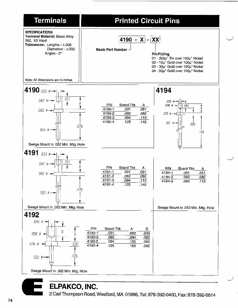
74
Terminals Printed Circuit Pins
SPECIFICATIONS Terminal Material: Brass Alloy 360, 1/2 Hard Tolerances: Lengths - ±.005
Diameters - ±.002
,41s_] - xi- ljl Bas;c Part Numbe,
Angles -2°
Note: All dimensions are in inches
4190 .023 ¢7 1-- t 1 .047 ¢ I
~ .062 r/J
. 047 r/J • A
.062 r/J i
4192 .040•: .~
.058 ¢ , I , A L,-r ~J I t
.078 r/J '---,-,-..........., .030
t .025 (/J .125
i
P/N 4192-1 4192-2 4192-3 4192-4
Swage Mount in .062 Min. Mtg. Hole
ELPAKCO, INC.
P/N BoardThk 4190-1 .031 4190-2 .062 4190-3 .094 4190-4 .125
P/N BoardThk 4191-1 .031 4191-2 .062 4191-3 .094 4191-4 .125
Board Thk A .031 .062 .062 .094 .094 .125 .125 .156
Pin Plating 01 - 200µ" Tin over 100µ" Nickel 02 - 10µ" Gold over 100µ" Nickel 03 - 30µ" Gold over 100µ" Nickel 04 - 50µ" Gold over 100µ" Nickel
4194
A • .051 A t .082 .070 ~
.113 . J, I .145
f__j~ A P/N Board Thk A
.051 4194-1 .031 .051
.082 4194-2 .062 .082
.113 4194-3 .094 .113
.145
Swage Mount in .043 Min. Mtg. Hole
D .040 .062 .062 .062
2 Carl Thompson Road, Westford, MA 01886, Tel: 978-392-0400, Fax: 978-392-6814
'J
i -._./

,,-...,.
Terminals
SPECIFICATIONS Terminal Material: Brass Alloy 360, 1/2 Hard
Printed Circuit Pins
Tolerances: Lengths - ±.005 Diameters - ±.002
Angles-2°
l419j - xi-Ill Basic Part Number
Note: All dimensions are in inches
4195 • t
I P/N
.Q20 4195-1
[ 4195-2
.300 4195-3
Swage Mount in .043 Min. Mtg. Hole
4196 .D25 0----1 I~
.070 ill P/N
4196-1 4196-2
030 0
Swage Mount in .043 Min. Mtg. Hole
4197 t A
t ! P/N 4197-1
.078 i/J .040
t t .030 </J .180
4197-2 4197-3
I Swage Mount in .043 Min. Mtg. Hole
ELPAKCO, INC.
Board Thk A .031 .051 .062 .082 .094 .113
BoardThk A .031 .051 .062 .082
Board Thk A .062 .082 .094 .110 .125 .145
Pin Plating 01 - 200µ" Tin over 100µ" Nickel 02 - 1 Oµ" Gold over 100µ" Nickel 03 - 30µ" Gold over 100µ" Nickel 04 - 50µ" Gold over 100µ" Nickel
4198
.04D r/J t A
i t .D62 'I! .040
t t .030 r/J .180
i
P/N BoardThk A 4198-1 .062 .082 4198-2 .094 .110 4198-3 .125 .145 4198-4 .156 .185
Swage Mount in .043 Min. Mtg. Hole
2 Carl Thompson Road, Westford, MA 01886, Tel: 978-392-0400, Fax: 978-392-6814 75

76
Terminals
SPECIFICATIONS Terminal Material: Brass Alloy 360, 1/2 Hard Tolerances: Lengths - ±.005
Diameters - ±.002 Angles - 2°
Note: All dimensions are in inches
t .165
l Press-fit in .057 Min. Mtg. Hole
4202 to 4205
Printed Circuit Pins
~-~ Basic Part Nu~ I
Pin Plating 01 - 200µ" Tin over 100µ" Nickel 02 - 1 0µ" Gold over 100µ" Nickel 03 - 30µ" Gold over 100µ" Nickel 04 - 50µ" Gold over 100µ" Nickel
4201 4219 - 4221
.030
1 .414
! Press-fit in .040 Min. Mtg. Hole
P/N B P/N B 4202-X .470 4219-X .100 4203-X .562 4220-X .150 4204-X .950 4221-X .300
80ARO THK.
_J_ 4205-X .870
-X Board Thk A C -X BoardThk A 1 .031 .080 .080 1 .031 .051 2 .062 .110 .110 2 .062 .082
3 .094 .113
Swage Mount in .043 Min. Mtg. Hole with Flat Surface Punch Swage Mount in .043 Min. Mtg. Hole
4213 to 4218 .02s 01 I 1t .040 0 I I I ~.0-40~-..----,
Tt i .070 0----r-,--,
.040 0
Swage Mount in .043 Min. Mtg. Hole
ELPAKCO, INC.
-X 1 2 3
P/N B 4213-X .150 4214-X .188 4215-X .300 4216-X .500 4217-X .750 4218-X 1.000
BoardThk A .031 .051 .062 .082 .094 .113
Swage Mount in .062 Min. Mtg. Hole
2 Carl Thompson Road, Westford, MA 01886, Tel: 978-392-0400, Fax: 978-392-6814
·J

/' ..
!'·
Terminals
SPECIFICATIONS Terminal Material: Brass Alloy 360, 1/2 Hard
Printed Circuit Pins
Tolerances: Lengths - ±.005 Diameters - ±.002
Angles-2°
~-~ Basic Part Nu~ I
Note: All dimensions are in inches
422~5~~ .040 t/1 I I .040 !
,:i .071 ~
B
.040 ~ -I .150
'_j Swage Mount in .043 Min. Mtg. Hole
.092 0
I
I .188 045 ~
iLJ Swage Mount in .064 Min. Mtg. Hole
4228 ¾ .050 0
t.125
➔ A
.093 ¢ ➔ I
.040 ~ .150
i Swage Mount in .076 Min. Mtg. Hole
ELPAKCO, INC.
P/N B 4222-X .170 4223-X .420
-X Board Tok A 1 .031 .051 2 .062 .082 3 .094 .113
P/N BoardThk A 4226-X .031 .062 4226-X .062 .094 4226-X .094 .125 4226-X .125 .156
P/N Board Thk A 4228-X .031 .051 4228-X .062 .082 4228-X .094 .113 4228-X .1 25 .145
Pin Plating 01 - 200µ" Tin over 100µ" Nickel 02 - 10µ" Gold over 100µ" Nickel 03 - 30µ" Gold over 100µ" Nickel 04 - 50µ" Gold over 100µ" Nickel
Swage Mount in .062 Min. Mtg. Hole
Swage Mount in .073 Min. Mtg. Hole
2 Carl Thompson Road, Westford, MA 01886, Tel: 978-392-0400, Fax: 978-392-681 4
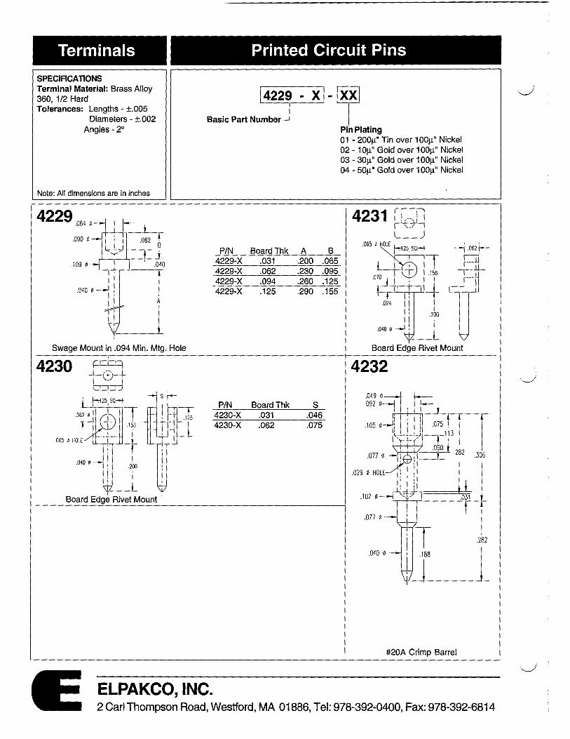
Terminals Printed Circuit Pins
SPECIFICATIONS Terminal Material: Brass Alloy 360, 1/2 Hard Tolerances: Lengths - ±.005
Diameters - ±.002 Angles -2°
~-~ Basic Part Nu~~r ~J . . . I
Note: All dimensions are in inches
4229 .064 0-j ...................... -~~
.090 ¢
P/N
.109 ¢ 4229-X 4229-X 4229-X
.040 9 4229-X
Swage Mount in .094 Min. Mtg. Hole
P/N 4230-X 4230-X
Board Edge Rivet Mount
ELPAKCO, INC.
BoardThk A B .031 .200 .065 .062 .230 .095 .094 .260 .125 .125 .290 .155
Board Thk s .031 .046 .062 .075
Pin Plating 01 - 200µ" Tin over 100µ" Nickel 02 - 10µ" Gold over 100µ" Nickel 03 - 30µ" Gold over 100µ" Nickel 04 - 50µ" Gold over 100µ" Nickel
4231 ~
7 .062f-
Board Edge Rivet Mount
4232
#20A Crimp Barrel
2 Carl Thompson Road, Westford, MA 01886, Tel: 978-392-0400, Fax: 978-392-6814
._)
.__J

Terminals
SPECIFICATIONS Terminal Material: Brass Alloy 360, 1/2 Hard Tolerances: Lengths - ±.005
Diameters - ±.002 Angles- 2°
Note: AU dimensions are In inches
4237to 4239
Swage Mount in .064 Min. Mtg. Hole
4242
Swage Mount in .067 Hole
4244 .on0 I~ .060 0,~ --+--1- I
.313
.053
Press-fit in .057 Mtg. Hole
Printed Circuit Pins
~~~ Basic Part Nu~ I
P/N A 4237-X .094 4238-X .219 4239-X .282
-X Board Thk B 1 .031 .063 2 .062 .094 3 .094 .125 4 .125 .156
P/N BoardThk A 4242-1 .031 .053 4242-2 .062 .084 4242-3 .094 .115
Wire Termination
Pin Plating 01 - 200µ" Tin over 100µ" Nickel 02 - 10µ" Gold over 100µ" Nickel 03 - 30µ" Gold over 100µ" Nickel 04 - 50µ" Gold over 100µ" Nickel
4243
#20A Crimp Barrel
ELPAKCO, INC. 2 Carl Thompson Road, Westford, MA 01886, Tel: 978-392-0400, Fax: 978-392-6814
79

80
Terminals
SPECIFICATIONS Terminal Material: Brass Alloy 360, 1/2 Hard Tolerances: Lengths - ±.005
Diameters - ±.002 Angles - 2°
Note: All dimensions are in inches
4245 .064 ~-1 f- j
j I i .062 •-J~,-,- A , r I
.125 ¢--['.;:::1=:'.J=:::=:::
l I .J)S
.090 ¢
.080 ~
l-1 Swage Mount in .094 Min. Mtg. Hole
42.~?HOL[ ' : -tr
: ll ! .090 . I 00 ¢ l_ ___ J -------r
y-r: !
.050 ¢ HOLE ~ [ i #'280
L~.-J _J_ .125 ¢- -1----r-'
I .Q30 , .. 4+L T 4249
.077 ¢
#20A Crimp Barrel
Printed Circuit Pins
l42j - x1-1y1 Basic Part Number
P/N BoardThk A 4245-1 .062 .094 4245-2 .094 .125 4245-3 .125 .156
4248 .1030
.067 ¢ HOLE
.141 ¢
.080 ¢
#16A Crimp Barrel
P/N A 4249-1 .200 4249-2 .375 4249-3 .500
Pin Plating 01 - 200µ" Tin over 100µ" Nickel 02 - 1 Oµ" Gold over 100µ" Nickel 03 - 30µ" Gold over 100µ" Nickel 04 - 50µ" Gold over 100µ" Nickel
4246 "064 ¢: :--'1-....-.090 0- : I J ,062 •-,t,~, ~ .090
' l I .12>¢--{:;=t=;.
l iLJ .080 ¢
Swage Mount in .094 Min. Mtg. Hofe
P/N A 4248-1 .200 4248-2 .375 4248-3 .500
ELPAKCO, INC. 2 Carl Thompson Road, Westford, MA 01886, Tel: 978-392-0400, Fax: 978-392-6814
\._,/
I ·__,;

Terminals
SPECIFICATIONS Terminal Material: Brass Alloy 360, 1/2 Hard Tolerances: Lengths - ±.005
Diameters - ±.002 Angles -2°
Note: All dimensions are in inches
4137 .025 r/J
.028 0 KNURL
.045 r/J
.018 0
.026 Min. Mtg. Hole
4140 CARRIER PIN
.072 0
.060 r/J--,L-f---',--f---'-=.;= .148
.053 r/J- ·~ .132
! .057 Min. Mtg. Hole
4142 .072 0 .031
. 062 ¢ --<'-+-¼-......+--"''O-'r28'--.173
.053 ¢
~ .020 0 .124
.059 Min. Mtg. Hole
Printed Circuit Pins
~-[@ Basic Part Nu::-J - I
4138
.026 Min. Mtg. Hole
4141 .072 0
E 0 KNURL fft ~ .185 .040 0
I .018 0 .155
.042-.055 Min. Mtg. Hole
4143 .072 0 .031
.060 0 __,-+-..,~---l--'·"'-!;02.:c..B -.165
.053 0 y .022 0 .180
I .057 Min. Mtg. Hole
Pin Plating 01 - 200µ" Tin over 100µ" Nickel 02 - 1 0µ" Gold over 100µ" Nickel 03 - 30µ" Gold over 100µ" Nickel 04 - 50µ" Gold over 1 00µ" Nickel
4139 .055 0
.038 0
.020 0
P/N E Mtg. Hole 4141-1 .058 .055 4141-2 .045 .042
4144
022 .125 . l .019 ! ---i . __J - ' ----1-i
~ 'I' 1--. 1 □8
.018 0 i .057 Min. Mtg. Hole
ELPAKCO, INC. 2 Carl Thompson Road, Westford, MA 01886, Tel: 978-392-0400, Fax: 978-392-6814
81

82
Terminals
SPECIFICATIONS Terminal Material: Brass Alloy 360, 1/2 Hard Tolerances: Lengths - ±.005
Diameters - ±.002 Angles- 2°
Note: All dimensions are in inches
4250 .072 r/J
.500
Press-fit in.042 Min. Mtg. Hole
Press-fit in .056 Min. Mtg Hole
4259 .068 0
.064 0
.058
.055 ¢-
.025 SQUARE
·±1 41
~ .480
j #20A Crimp Barrel
Wire Wrap Terminals
~-[$ Basic Part Numb~ I
4251 .025 SQUARE
.050 0-.058 0 .072 ¢
.520
Press-fit in.053 Min. Mtg. Hole
P/N # ofWra~s A 4252-1 1 .260 4253-2 2 .360 4254-3 3 .500 4255-1 1 .260 4256-2 2 .360 4257-3 3 .500
4260 .066 ¢
.061
Press-fit in .060 Mtg. Hole
C .072 .072 .072 .062 .062 .062
Pin Plating 01 - 200µ" Tin over 100µ" Nickel 02 - 10µ" Gold over 100µ" Nickel 03 - 30µ" Gold over 100µ" Nickel 04 - 50µ" Gold over 100µ" Nickel
4258 .058 r/J KNURL
.065 r/J - ''---'-,..J
.025 SQUARE
Press-fit in .055 Min. Mtg. Hole
4277 TT .072 0
~ 375
.025 SQUARE
i Press-fit in .057 Min. Mtg Hole
.068 r/J
.057 r/J
.060 r/J KNURL .057 0
.052 0
Press-fit in .056 Mtg. Hole
ELPAKCO, INC. 2 Carl Thompson Road, Westford, MA 01886, Tel: 978-392-0400, Fax: 978-392-6814
..._____,;·

(
Terminals
SPECIFICATIONS Terminal Material: Brass Alloy 360, 1/2 Hard Tolerances: Lengths • ±.005
Diameters • ±.002 Angles• 2°
Note: All dimensions are in inches
4262 to 4264 .043
A
i Press-fit in.056 Min. Mtg. Hole
4266 .025 ¢
.052 0
Press-fit in . 59 Min. Mtg Hole
Press-fit in .057 Min. Mtg. Hole
Wire Wrap Terminals
~-~ Basic Part Num=~ !
P/N #of Wraps A 4262-1 1 .260 4263-2 2 .360 4264-3 3 .500
4267
.500
Press-fit in.056 Min. Mtg. Hole
P/N #ofWraps A 4268·1 1 .260 4269-2 2 .360 4270-3 3 .510
Pin Plating 01 - 200µ" Tin over 100µ" Nickel 02 • 1 0µ" Gold over 100µ" Nickel 03 - 30µ" Gold over 100µ" Nickel 04 • 50µ" Gold over 100µ" Nickel
4265.019 0 .147
l
.053
.025 SQUARE
.510
Press-fit in .057 Min. Mtg. Hole
4283 t¥. ~ ~~ .072 ."160
STRAIGHT KNURL 3 .425
.0615 0 Q040 660 AFTER I -,- · KNURi.
.056 0
.235
4284 .025 SQ.
.560
.012 ~ MAX FLAT --H-
ELPAKCO, INC. 2 Carl Thompson Road, Westford, MA 01886, Tel: 978-392-0400, Fax: 978-392-6814
83

84
Series PMP DESCRIPTION
This section shows one of the most comprehensive lines of terminals in the electronics industry.
Elpakco stocks large quantities of every possible configuration of terminals in a variety of plating options.
Also many of the terminals can be customized to customer supplied specifications.
SPECIFICATIONS Terminal Material: Brass Alloy 360 1/2 hard per QQ-B-626. Phosphor Bronze Alloy 544 per QQ-B-750. Terminal Plating: Gold per MIL-G-45204, Type I, Grade C. SilverperQQ-S-365, Type Ill, Grade A. Tin per MIL-T-10727, Type I. Electro Solder per MIL-P-81728. Nickel per QQ-N-290. Copper per MIL-C-14550.
Technical Specifications
GENERAL SPECIFICATIONS When applicable, Elpakco products and procedures are designed to meet the
following general specifications:
MIL-STD-105 MIL-STD-109 MIL-STD-202E MIL-STD-1130B MIL-STD-1344A MIL-STD-45662 MIL-C-39029 MIL-I-45208 MIL-S-83505 ASTM-B487-79 ASTM-A754-79
Sampling procedures Quality assurance terms and conditions Test measures for electronic and electrical component parts Connections, electrical, solderless, wrapped Test methods for electrical connectors Calibration system requirements General specifications for contacts, electrical connector Inspection equipment, acquistion, maintenance and disposition of General Specification for sockets (lead, electronic components) Measuring metal coating by examination of a cross section Standard test methods for coating thickness by X-ray florescence
All Terminals are made to exacting
standards! L ______________________ __.1----------------------------------------------------------=-'
Series PMP
CUSTOM TERMINALS Elpakco has a large inventory
of material used for the manufacturing of custom solder terminals. Below is a list of what type of raw material is available (measured in diameters):
Brass Alloy 360 1/2 hard: .072 - .078 - .125 - .156 - .187 Brass Alloy 360 1/4 hard: .072 - .078 Brass Tubing: .072 OD x .020 ID -.072 OD x .025 ID Phosphor Bronze: .062 - .072 - .078
TOLERANCES Length: ±.005 Diameters: ±.002 Angles: ±2°
Note: All dimensions are in inches
Ordering Information
1102 - 3071-~
Basic Part Number Terminal Plating 1 - 300µ" Silver over 100µ" Copper 3 - 200µ" Tin over 100µ" Nickel 4 - 300µ" Electro-Solder over 100µ"
Copper
Note: Standard plating is Silver (-1). Other plating options are avilable upon request.
ELPAKCO, INC. 2 Carl Thompson Road, Westford, MA 01886, Tel: 978-392-0400, Fax: 978-392-6814
,____,;j

,r-,.
Series PMP Turret Solder Terminals
~
04
.145 ~----c~~ 1
Part Number 'A' . Bd. Tk. 1D6-1A .078 .031 106-18 .109 .062 1D6-1C .140 .094 1D6-1D .172 .125 106-1E .195 .156 1D6-1F .234 .188 106-1G .293 .250
Swage Mount in .116 Hole
1D5-4
Part Number 'A' Bd. Tk. 1D5-4A .075 .031 105-4B .105 .062 1D5-4C .135 .094 1D5-4D .165 .125
Swage Mount in .094 Hole
1KD4-7 .064 0 HOLE -j r ~ . ~
.\25 ¢
L___,...--,-1~, l =+=w
Part Number-c_-'-__J'A+.L
1KD4-7A .Q75 .031 1KD4-7B .105 .062 1KD4-7C .135 .094 1KD4-7D .165 .125
Press-fit & Swage Mount in .088 Hole
1 KD6-2A .075 .031 1 KD6-2B .105 .062 1 KD6-2C .135 .094 1KD6-2D .165 .125 1KD6-2E .195 .156 1 KD6-2F . 230 .187
Swage Mount in .116 Hole
Part Number 'A' 'B' Bd. Tk. 1D5-5A .075 .063 .031 1D5-5B .105 .093 .062 105-5C .135 .093 .094 105-5D .165 .093 .125
Swage Mount in .094 Hole
1D3-8
.046 0 KOLE -----j r I .061 0 l+J ~.--L□,-7 -.□2-,s~l
Part Number 1D3-8AA 1D3-8A 1D3-8B 1D3-8C 1D3-8D
f I n,·T ~ 'A'
.037 ,053 .084 .115 .147
Bd. Tk. .016 .031 .062 .094 .125
S~age Mount in .064 Hole
ELPAKCO, INC.
11 .(]l]
.1!-6 . _j_
ml
Part Number 'A' Bd. Tk. 1FKD6-3A .075 .031 1FKD6-3B .105 .062 1FKD6-3C .135 .094 1FKD6-3D .165 .125 1KFD6-3E .195 .156 1KFD6-3F .230 .187
Swage Mount in .116 Hole
.064 ¢ KOLE
.125 0
1D4-6
.062 A
l
.092 I l t .237
_,--'-'-'-,~
Part Number 'A' Bd. Tk. 1D4-6A .075 .031 104-6B .105 .062 104-6C .135 .094 1 D4-6D .165 .125
Swage Mount in .094 Hole
1KD3-9
~t i
.093 0
L_____,.---.---JJI: i ~
Eld. Tk. Part Number 'A' 1KD3-9AA .037 .015 1KD3-9A .054 .031 1KD3-98 .084 .062 1KD3-9C .115 .188 1KD3-9D .147 .125
Press-fit & Swage Mount in .059 Hole
2 Carl Thompson Road, Westford, MA 01886, Tel: 978-392-0400, Fax: 978-392-6814 85
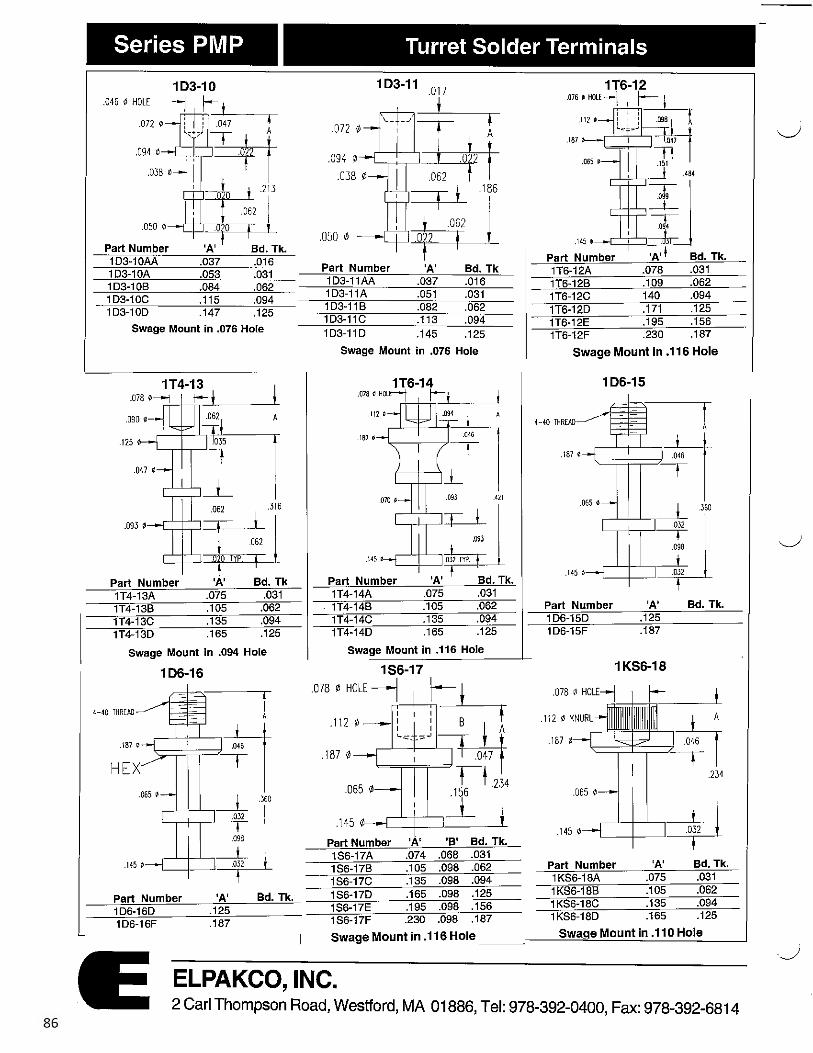
86
Series PMP
1D3-10 .046 0 HOLE
.094 ~
7 r-1 : : _0 ....... 47---~-
\' ~! Part Number
'~~2j3 ·P 'A' Bd. Tk.
103-10AA .037 .016 1D3-10A .053 .031 103-10B .084 .062 1D3-10C .115 .094 103-10D .147 .125
Swage Mount in .076 Hole
1T4-13 I .078 0--1 t--_,_J ___ _.__
.125 0 1-i .093 0
Part Number
062 .316
Tw ,;, l 'A' Bd. Tk
1T4-13A .075 .031 1T4-13B .105 .062 1T4-13C .135 .094 1T4-13D .165 .125
Swage Mount in .094 Hole
1D6-16
4-40 THREAD t A
.187 0
HEX ~~ .065 ~ .----L~..__,__J_ .36D
.032 -r
.098
.145 ¢ ,---,.-1---'---i_L
.032
Part Number 'A' Bd. Tk. 106-16D .125 1D6-16F .187
Turret Solder Terminals
1D3-11 _017
' '"- _.,--.- l .072 0 ,
.094 I/)- I ---+--M .0381/J-- ~ i
.050 0
=TI .186
w I
Part Number 'A' Bd. Tk 1D3-11AA .037 .016 1D3-11A .051 .031 1D3-11B .082 .062 1D3-11C .113 .094 103-110 .145 .125
.145 1--ICJCJ
Part Number 1T6-12A 1T6-12B 1T6-12C 1T6-12D 1T6-12E 1T6-12F
Bd. Tk. .031 .062 .094 .125 .156 .187
Swage Mount in .076 Hole Swage Mount in .116 Hole
1 D6-15
4-40 THREAD
.167 o
.09, .421
.....-'-1--'---;l Part Number 'A' Bd. Tk.
.145
1T4-14A .075 .031 - 1T4-14B .105 .062 Part Number 'A' Bd. Tk.
1T4-14C .135 .094 1D6-15D .125 1T4·14D .165 .125 1D6-15F .187
Swage Mount in .116 Hole
1S6-17 1 KS6-18
.078 ¢ HOLE '.
1
! •-+
1\2r/J---I I ---;---;-r . I I ' A
.187¢ '--,:: 1-::,-'~
I A
' l .046 -.- I .234
.065 1/J
.145 1/J
n .........L--+--1-~ 1 I' T
Part Number 'A' 'B' Bd. Tk. 1S6-17A .074 .068 .031
.065 0
.145 0 ~ 'A' Bd. Tk.
.075 .031
.105 .062
.135 .094
.165 .125
1S6-17B .105 .098 .062 Part Number 1 S6-17C .135 .098 .094 1 KS6-18A 1S6-17D .165 .098 .125 1KS6-188 1S6-17E .195 .098 .156 1KS6-18C 1 S6-17F .230 .098 .187 1 KS6-18D
Swage Mount in .116 Hole ___ ---~S_w_a ____ a_e_M_o_u_n_t_in_._1_1 O_H_o_le __ _J
ELPAKCO, INC. 2 Carl Thompson Road, Westford, MA 01886, Tel: 978-392-0400, Fax: 978-392-6814

Series PMP
1S4-19
.064 ¢ HOLE - --J f-l I i y
. 125 0
i·i~062T A ' ' i...-:;.--;:,,J
' .046 '===-== • t
i ~ ·T .040 ¢
. 075 0
Part Number 'A' Bd. Tk. 1S4-19A .075 .031 1S4-19B .105 .062 1S4-19C .135 .094 1S4-190 .165 .125
Swage Mount in .094 Hole
1$2-25
.028 r/J HOLE--j t-- f lJ~
.047 r/J 7 A
t
1S2-25AA .035 .016 1S2-25A .054 .031 1S2-25B .084 .062 1S2-25C .115 .094 1S2-25D .147 .125
Swa~e Mount in .052 Hole
Turret Solder Terminals
1KS4-20 1$3-21
.063 0 HOLE 7 t
.046 ¢ HOLE--J r, .087 ¢ t l · .052 .072 rt,-
8 A
l .012 ! .125 ~ .046 .094 ¢
--r .038 0 .067 .109 .040 ¢ .181
t ! .050 ¢ ~ ' _l .075 ~ .025 Part Number 'A' Bd. Tk .
+ 1S3-21 AA .037 .016 Part Number 'A' 'B' 'D' Bd. Tk. 1S3-21A .053 .031 1KS4-20A .075 .040 .030 .031 1S3-21 B .084 .062 1KS4-20B .105 .060 .030 .062 1S~·21C .115 .094 1KS4-20C .135 .060 .060 .094 1S3-210 .147 .125 1KS4-20D .165 .060 .060 125
Swage Mount in .077 Hole Press-fit & Swage Mount in .089 Hole
1S2-23 1S3-24_Q17
.046 f/i HOLE -----j j------~
.062 1/J A
i ' L-,-4-.,......J .025 l t f .093
.023 J .050 1/J
'
.072 1/J
t \....I • ../ -~.- !
L.-.--'--,--J-!~ ~.104
t f Part Number 'A' Bd. Tk. 1S2-23AA .037 .016 1S2-23A .053 .031 1S2-23B .084 .062 1S2-23C .115 .094 1S2-230 .147 .125
Part Number 1S3-24AA 1S3-24A 1S3-24B 1S3-24C
'A' Bd. Tk. .037 .016 .051 .031 .082 .062 .113 .094 .145 .125 1S3-24D
Swage Mount in .076 Hole Swage Mount in .067 Hole
1P4-26
.040 ¢ .173
l
L....-:::::i::::=-..-4 j .OS3 ~
.IW0~:~~~~- ·r : 1 .093 0 i
.187 ~
Part Number 'A' Bd. Tk. Part Number 'A' Bd. Tk. 1 P4-26A .075 .031
1S6-26A .075 .031 1 S6-26B .105 .062
1P4-26B .105 .062 1S6-26C .135 .094
1P4-26C .135 .094 1S6-260 .165 .125
- 1P4-26D .165 .125 Swage Mount in .094 Hole
Swa!le Mount in .094 Hole
ELPAKCO, INC. 2 Carl Thompson Road, Westford, MA 01886, Tel: 978-392-0400, Fax: 978-392-6814
87

88
Series PMP Turret Solder Terminals
2D6-31A .075 .031 2D6-31 B .105 .062 206-31 C .135 .094 2D6-310 .165 .125 2D6-31E .195 .156 2D6-31 F .230 .187
Swage Mount in .116 Hole
2S6-34
.112 ¢
A
.187 ~ ~=ti .203
: : =t--1 -l .078 ¢ I--
.145 ~
Part Number 'A' Bd. Tk. 2S6-34A .075 .031 2S6-34B .105 .062 2S6-34C .135 .094 2S6-34D .165 .125 2S6-34E . 195 . 156 2S6-34F .230 . 187
Swage Mount in .116 Hole
2D6-29A .075 .031 2D6-29B .105 .062 2D6-29C .135 .094 2D6-29D .165 .125
Swage Mount in .116 Hole
187,
.043 •--I Part Number 2D6-32A 206-32B 2D6-32C 2D6-32D 2D6-32E 2D6-32F
_l_ J12
~ .0)2
.075
.105
.135
.165
.195
.230
.062
Bd. Tk. .031 .062 .094 .125 .156 .187
Swage Mount in .116 Hole
2S5-35 .078 0 HOLE -1
.108 0
2S5-35A .075 .031 2S5-35B .105 .062 2S5-35C .135 .094 2S5-35D .165 .125 2S5-35E .195 .156 2S5-35F .230 .187
Swage Mount in .113 Hole
ELPAKCO, INC.
Part Number 2D6-30A 2D6-30B 2D6-30C 2D6-30D
.1 56 ¢
.075 .031
.105 .062
.135 .094
.165 .125
tt L ! ' _L 328
i: ~ j I : ___i_ .109 ¢-----1:::'.1:::P~
Part Number 'A' Bd. Tk. 2D5-33A .075 .031 2D5-33B .105 .062 2D5-33C .135 .094 2D5-33D .165 .125
Swage Mount in .082 Hole
2S5-36
.064 0 HOLE 7 1 r
I I
I .091 0-- 1
l I I I
.120¢
Part Number 2S5-36A 2S5-36B 2S5-36C 2S5-36D
---~
I
I I
I I I .266
Ii~ .032
'A' Bd. Tk. .077 .031 .107 .062 .137 .094 .167 125
Swage Mount in .094 Hole
2 Carl Thompson Road, Westford, MA 01886, Tel: 978-392-0400, Fax: 978-392-6814

Series PMP Turret Solder Terminals
Part Number 'A' Bd. Tk. 2S5-37A .075 .031 2S5-37B .105 .062 2S5-37C .135 .094 2S5-37D .165 .125
Swage Mount in .094 Hole
2S3-40 .046 ¢ HOLE---j )--
...:....;~----~
.062 t/J : I : f i I i + . t
.093 t/J
Part Number 2S3-40AA 2S3-40A 2$3-40B 2S3-40C 2S3-40D
-r-1.~
: : + .045 .094 I I
'A' .037 .053 .084 .115 .147
f i Bd. Tk. .016 .031 .062 .094 .125
Swage Mount in .067 Hole
3DO8-43
Part Number 'A' Bd. Tk. 3DD8-43A .075 .031 3D08-43B .105 .062 3DD8-43C .135 .094 3DD8·43D .165 .125 3DD8-43E .195 .156 3DD8-43F .230 .187 3DD8-43G .293 .250
Swage Mount in .206 Hole
2S4-38
A
=H .125 ¢
--. .156
=,=---L Part Number 'A' Bd. Tk. 2S4-38A .053 .031 2S4-388 .084 .062 2S4-38C .115 .094 2S4-38D .147 .125
Swage Mount in .067 Hole
3DD10-41C .135 .094 3DD10-41D .165 .125 3DD10-41E .195 .156 3DD10·41F .230 .187 30D10-41 G .293 .250
Swage Mount in .264 Hole
t 1 7° .032 I JULl
.250 r/J
.062 1/J
~ _J .357
~ ELPAKCO, INC.
2S4-39
.043 '/J HOLE 7 r ----r-
.071 1/J A
.125 r/J +l .187
~ .096 r/J 0
C'SINK 45° Part Number 'A' Bd. Tk. 2S4-39AA .037 .016 2S4-39A .054 .031 2S4-39B . . 084 .062 2S4-39C .115 .094 2S4-'39D .147 .125
Swage Mount in .076 Hole
3DD8-42
Part Number
11--c:±::i 0:1 t t
. ., 41 l ~ 406
®Bd.Tk 3DD8-42B ,075 .031 3DD8-42C .105 .062 3D08-42D .135 .094 30 D8-42E .165 .125 3DD8-42F .195 .156 3DD8-42G .230 .187
Swage Mount in .205 Hole
3KD8•44
~ mu .144 If .312
I ~ .250
~ .344 w Part Number 'A' Bd. Tk. 3KD8-44B .105 .062 3KD8-44C .135 .094 3KD8-44D .165 .125 3KD8-44E .195 .156 3KD8-44F .230 .187
Swage Mount in .206 Hole
2 Carl Thompson Road, Westford, MA 01886, Tel: 978-392-0400, Fax: 978-392-6814 89

90
Series PMP Turret Solder Terminals
.156 •
.187 •
Part Number 3DD6-45A 3D06-45B 3DD6-45C 3D06-45D 3DD6-45E 3ED6451F
Bd.Tk .075 .031 .105 .062 .135 . 094 .165 .125 .195 .156 .230 .187
Swage Mount in .159 Hole
.040
.090 0 --~1""""171
.125 ¢ __ ....___]__
Part Number 'A' 3DD4-48A .075 3D04-48B .105 3DD4-48C .135 3D04-48D .165
Bd. Tk. .031 .062 .094 .125
Swage Mount in .094 Hole
3PD5-51
3PD5-51A .062 .031 3PD5-51 B 094 .062 3PD5-51C .125 .094 3PD5-51D .156 .125 3PD5-51E .195 .156 3PD5-51 .230 .187
Swage Mount In .120 Hole
30D5-46 i
.032
I
.156 ~
t .020 .T
A
--.-t-~~---·04_5 '
-093 0
__,~--., T 1, I l Part Number 'A' Bd. Tk . 3DD5-12A .075 .031 30D5-12B .105 .062 3DD5-12C .135 .094 30D5-12D .165 .125
Swage Mount in .129 Hole
.094 0
3DD3-49A .051 .031 3D03-49B .082 .062 3DD3-49C .113 .094 3D03-49D .145 .125
Swage Mount in .076 Hole
_oga 3PD5-5~
~t f .150
.OOB ~ HO t
ll'JB •
Part Number 'A' Bd. Tk. 3PD5-52B .105 .062 3PD5-52C .135 .094 3PD5-52D .165 .125 3PD5-52E .195 . 156 3PD5-52F .230 . 187
Swage Mount in .144 Hole
ELPAKCO, INC.
3KDD5-47
.1 24
020 _J I
~~¢-~~ I l} I 'A' .020 Bd. Tk. Part Number
3KDD5-47A .075 .031 3KDD5-47B .105 .062 3KDD5-47C .135 .094 3KDD5-47D .165 .125
Swage Mount in .125 Hole
3PD8-50B .105 .062 3PD8-50C .135 .094 3PD8-50D .165 .125 3PD8-50E .195 .156 3PD8-50F .230 .187
Swage Mount in .186 Hole
30S8-53 t .144 ~
.187
t .250
3DS8-53A .075 .031 30S8-53B .1 05 .062 3DS8-53C .135 .094 3DS8-53D .165 .125 30S8-53E .195 .156 3DS8-53F .230 .187
~ ___ S_wage Mount in .206 Hole __
2 Carl Thompson Road, Westford, MA 01886, Tel: 978-392-0400, Fax: 978-392-6814
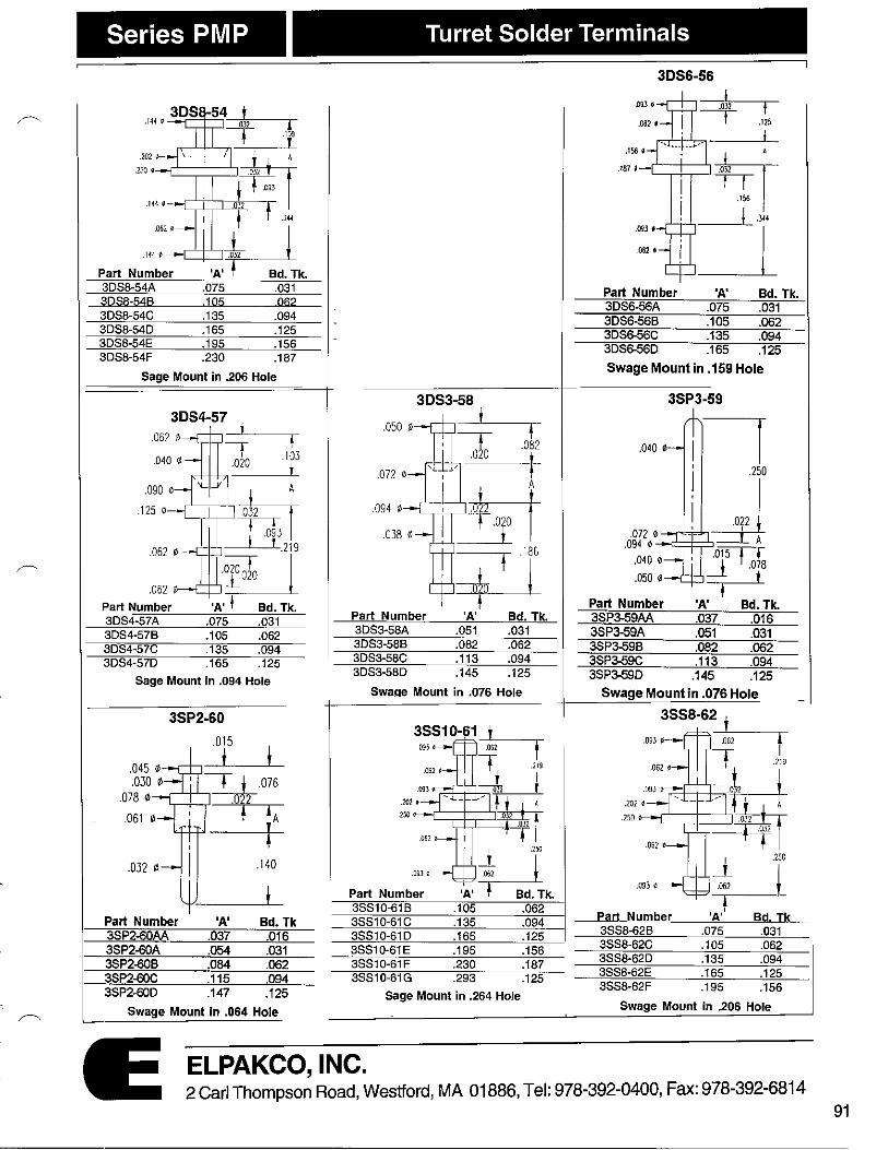
Series PMP Turret Solder Terminals
3DS8-54A .075 .031 3DS8-54B .105 062 3DS8-54C .135 .094 3DS8-54D .165 .125 3DS8-54E .195 .156 3DS8-54F .230 .187
Sage Mount in .206 Hole
3DS4-57
t f .082
103 t
' .125 0 .094 ¢
Part Number 3DS4-57A .075 .031 3D84-57B .105 .062 3DS4-57C .135 .094 3D84-57D .165 .125
Sage Mount in .094 Hole
l .1a6
~ Part Number 'A' Bd. Tk. 3OS3-58A .051 .031 3D83·58B .082 .062 3DS3-58C .113 .094 3D83-58D .145 .125
Swaqe Mount in .076 Hole
3SP2-60
Part Number 3SS10-61B .105 .062
Part Number 'A' Bd. Tk 3SS10-61C .135 .094 3SP2-60AA .037 .016 3S$10-61D .165 .125 3SP2-60A .054 .031 3S$10-61E .195 .156 3SP2-60B .084 .062 3SS10-61F .230 .187 3SP2-60C .115 .094 3SS10-61G .293 .125 3SP2-60D .147 .125 Sage Mount in .264 Hole
Swage Mount In .064 Hole
ELPAKCO, INC.
3D86-56
Part Number 'A' Bd. Tk. 3DS6-56A .075 .031 3D$6-56B .105 .062 3DS6-56C .135 .094 30S6-56D .165 .125
Swage Mount in .159 Hole
35P3-59
.040 0 ,7 j .250
---'=id-,i ~022A .072 0--~ .094 0 --c~==:,
.040 0
.050 0
Part Number 'A' Bd. Tk. 3SP3-59AA .037 .016 3SP3-59A .051 .031 3SP3-59B .082 .062 3SP~59C .113 .094 3SP~59D .145 .125
Swage Mount in .076 Hole
Part Number 3SS8-62B 3SS8-62C 3S88-62D 3SS8-62E 3SS8-62F
Swage Mount in .206 Hole
2 Carl Thompson Road, Westford, MA 01886, Tel: 978-392-0400, Fax: 978-392-6814 91
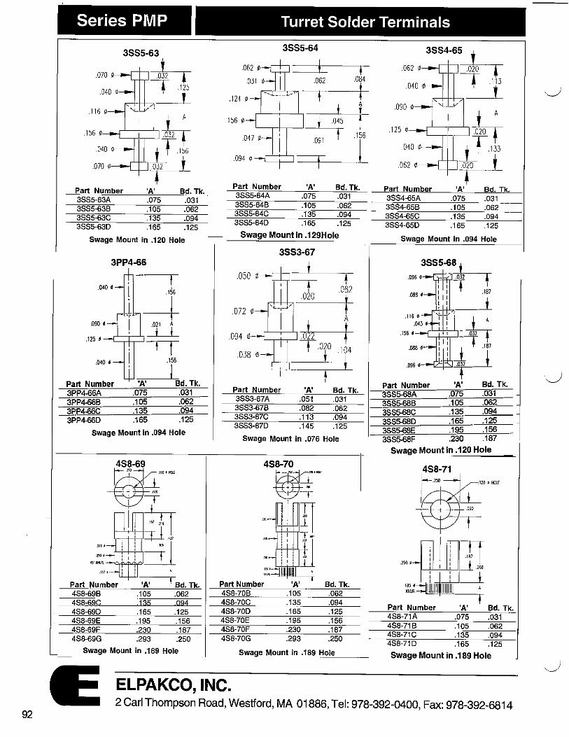
92
Series PMP
3SS5-63
.070 ~
.040 0
Part Number 3SS5-63A 3SS5-63B 3SS5-63C 3SS5-63D
h -r .125
t
'A' Bd. Tk. .075 .031 .105 .062 .135 .094 .165 .125
Swage Mount in .120 Hole
3PP4-66
t
-i .090 • .021 A
i i t t
.O◄O ~ .156
J Part Number 'A' Bd. Tk. 3PP4-66A .075 .031 3PP4-66B .105 .062 3PP4-66C .135 .094 3PP4-66D .165 .125
Swage Mount In .094 Hole
Part Number 'A' 4SB·69B .105 4SB-69C 135 4S8-69D .165 4S8-69E .195 4S8-69F .230 4S8-69G .293
I Bd. Tk. .062 094
.125 .156 .187 .250
Swage Mount in .189 Hole
Turret Solder Terminals
3$S5-64
♦ .062 .084
t '--~+-.----' t .045
~ .156 091 I
.094 r/J -~ r~;:::~ =+--_,_ __ __.f_
156 ~
Part Number 'A' Bd. Tk. 3SS5-64A .075 .031
.125 r/J
.062
Part Number
3SS5-64B 3SS4-65A
..-------.---,~
l__T_,33
t-1 'A' Bd. Tk.
.105 .075 .031
.062 3SS5-64C
3SS4-65B .135 .094
38S5-64D .165 .125
.105 .062 3SS4-65C .135 .094 3SS4-65D .165 .125
Swage Mount in .129Hole Swage Mount in .094 Hole
3SS3-67
.050 ¢ i
l I
.082
.072 ¢ t
Part Number 'A' f
Bd. Tk. 3SS3-67A .051 .031 3SS3-678 .082 .062 3SS3-67C .113 .094 38S3-67D .145 .125
Part Number 'A' Bd. Tk. 3SS5-68A .075 .031 35S5-68B .105 .062 3SS5-68C .135 .094 3S$5-68D .165 .125 3SS5-68E .195 .156
Swage Mount in .076 Hole 35S5-GSF .230 .187
Swage Mount in .120 Hole
120 o 00.I
.250 I
Part Number Bd. Tk. 4S8-70B .105 .062 4S8-70C .135 .094 4S8-70D .165 . 125 4S8-70E .195 .156 4S8-70F .230 .187 4S8-70G .293 .250
Part Number 'A' Bd. Tk . 4S8-71A .075 .031 4$8-71 B .105 .062 4S8-71C .135 .094 4$8-71D .165 .125
Swage Mount in .189 H_o~le __ _ Swage Mount in .189 Hole
ELPAKCO, INC. 2 Carl Thompson Road, Westford, MA 01886, Tel: 978-392-0400, Fax: 978-392-6814
"-J'

-
93
Series PMP Slotted Solder Terminals
Part Number 'A' Bd. Tk. 4S7-72A .075 .031 4S7-72B .105 .062 4S7-72C .135 .094 4S7-720 .165 .125
Swage Mount in .138 Hole
.ut •
Part Number ;.-, Bd. Tk. 4S6-75A .075 .031 4S6-75B .105 .062 4S6-75C .135 .094 4S6-75D .165 .125
Swage Mount In .116 Hole
4S3-78
♦_J_ .034
~
.043 SLOT 7 1 t-
094 ~ i TI
.040 ~ HOLE--j Part Number 1A1 Bd, Tk. 4S3·78A .053 .031 4S3-78B .084 .062 4S3-78C .115 .094 4S3-78D .147 .125
Swage Mount in .067 Hole
.500
.172 ti Part Number 'A' • Bd. Tk. 4S7-73A .075 .031 4S7-73B .105 .062 4S7-73C .135 .094 4S7-730 .165 .125
Swage Mount in .139Hole
4S5-76
~i .,, . ..,, ..... I +-TT .. , "" i _J .iu,
Part Number 4S5-76A 4S5-76B 4S5-76C 4S5-76D 4S5-76E 4S5-76F
=L ·"'
71 i 'A'
. 075 105
,135 .165 .195 .230
Bd. Tk. .031 062 094
.125
.156
.187 Swage Mount in .116 Hole
4D5-79 ~~•QC
.12, 1T7 I _.1 .,,,
~
Part Number 4D5-79A 4D5-798 4D5-79C 405-79C
.105
.135
.165
Bd. Tk. .031 .062 .094 .125
Swage Mount In .082 Hole
ELPAKCO, INC.
@_L ····~ ; c- 4
_,.,. i TT ' .,1 \)
! _J "' ! ii _.__ I ! •l_i_
m• j, ! .01' ,IW--j f-
Part Number 'A' Bd.Tk 4S6-74A .075 .031 4S6-74B .105 .062 4S6-74C .135 .094 486-74D .165 .125 4S6-74E .195 .156 486-74F .230 .187
Swage Mount in .116 Hole
4S5-77
i-⇒ 11: Tf l I l _L .. ll2
.1S6 t
i l I .112 t
.031 o HOLE --j I--Part Number 'A' Bd. Tk . 4S5-77A .045 .031 4S5-77B .094 .062 4S5-77C .125 .094 4S5-77D .156 .125 4S5-77E .195 .156 4S5-77F .230 .187
Swage Mount in .116 Ho_le __ _
4D5-80
.156
Part Number 4D5-80A 4D5-80B 4D5-80C 4D5-800
0'1 • HOU
Bd. Tk. .031 .062 .094 .125
swage Mount In ,091 Hole
2 Carl Thompson Road, Westford, MA 01886, Tel: 978-392-0400, Fax: 978-392-6814

94
Series PMP Turret & Double Ended Solder Terminals
Part Number 'A' Bd. Tk 52S6-81A .075 .031 52S6-81B .105 .062 52S6-81C .135 .094 52S6-81D .165 .125 52S6-81E .195 .156 52S6-81F .230 .187
swage Mount In .138 Hole
Part Number 'A' 'D' Bd. Tk. 5S6-82A .075 .068 .031 5S6-82B .105 5S6-82C .135
,098 .062 .098 .094
5S6-82D .165 .098 .125
swage Mount In .116 Hole
Swage Mount in .116 Hole Swage Mount in .067 Hole
.125 •
Part Number 'A' 5D4-88A 075 5D4-888 .105 5D4-88C .135 504-88D .165
swage Mount In .094 Hole
ELPAKCO, INC.
.070 e HOLE-j
Part Number 52S6-63A 52S6-638 52S6-63C 52S6-63D 52S6-63E 52S6-63F
'A' Bd. Tk. .037 .016 .053 .031 .084 .061 .115 .094 .147 .125 .230 .187
Swage Mount in .116 Hole
5S4-86A .075 .031 5S4-86B .105 .062 5S4-86C .135 .094 5S4-86D .165 .125
Swage Mount in .094 Hole
2 Carl Thompson Road, Westford, MA 01886, Tel: 978-392-0400, Fax: 978-392-6814

' I ,·
Series PMP
2D6-129
r-
,149 0
2D6-129A .078 .031 2D6-129B .109 .062 2D6-129C .140 .094 2D6-129D .171 .125
Swage Mount in .116 Hole _
453-178
♦=f
Part Number 'A' Bd. Tk. 4S3-178A .045 .031 453-1786 .094 .062 4S3-178C .125 094 4S3-178D .156 .125
Swage Mount in .067 Hole
Double Ended Solder Terminals
2S4-139
.043 0 HOLE 7 r ---~
.071 r/J
.125 r/J
.096 r/J
Part Number 2S4-139A .062 .031 2S4-139B .093 .062 2S4-139C .125 .094 2S4-139D .156 .125
Swage Mount in .076 Hole
.OS4 f -
.061 0
.043 f HOL( --l 1--'A' Part Number 4S3-278AA .037 4S3•278A .053 4S3-278B .084
4S3-278C .115 453-278D .147
Bd, Tk. .016 .031 .001
.094
.125 Swage Mount in .067Hole
ELPAKCO, INC. 2 Carl Thompson Road, Westford, MA 01886, Tel: 978-392-0400, Fax: 978-392-6814
95

104
Series MP
DRAWINGS
B
A
DRAWINGS .025 0 X .045 DEEP
.020 Lt L A
1J 9070. B
.040
DRAWINGS---j ~050 0
T .040 0 El
DRAWINGS
.064 ~62 DEEP J
ITT .090 0
.125 t;i--l B
.090 0-- ! Note: All dimensions are in inches
Mini Pins
ORDERING INFORMATION
Part Number 'A' 'B' MP-125-1 .020 .400 MP-125-2 .020 .600 MP-125-3 .020 .900 MP-130-1 .032 .400 MP-130-2 .032 .600 MP-130-3 .032 .900 MP-135-1 .040 .400 MP-135-2 .040 .600 MP-135-3 .040 .900 MP-140-1 .062 .400 MP-140-2 .062 .600 MP-140-3 .062 .900
Standard Plating - Nickel (other Options are Available)
ORDERING INFORMATION
Part Number 'A' 'B' Board Thickness MP-160-1 .051 .200 .031 MP-160-2 .082 .200 .062 MP-162-1 .051 .250 .031 MP-162-2 .082 .250 .062 MP-165-1 .051 .300 .031 MP-165-2 .082 .300 .062 MP-166-1 .051 .400 .031 MP-166-2 .082 .400 .062 MP-170-1 .051 .600 .031 MP-170-2 · .082 .600 .062 MP-172-1 .051 .800 .031 MP-172-2 .082 .800 .062 MP-175-1 .051 .900 .031 MP-175-2 .082 .900 .062
Standard Plating - Gold (other Optlons are Available)
ORDERING INFORMATION Part Number 'A' 'B' MP-200-1 .051 .140 MP-200-1 .082 .140 MP-200-3 .113 .140 MP-205-1 .051 .250 MP-205-2 .082 .250 MP-205-3 .113 .250 MP-205-4 .145 .250
Board Thickness .031 .062 .094 .031 .062 .094 .125
Standard Plating - Silver (other Options are Available)
ORDERING INFORMATION
Part Number 'A' 'B' Board Thickness MP-230-1 .075 .150 .031 MP-230-2 .105 .150 .062 MP-230-3 .135 .150 .094 MP-235-1 .075 .300 .031 MP-235-2 .105 .300 .062 MP-235-3 .135 .300 .094
Standard Plating - Gold (Other Options are Available)
ELPAKCO, INC. 2 Carl Thompson Road, Westford, MA 01886, Tel: 978-392-0400, Fax: 978-392-6814

Series MP Mini Pins
,~ DRAWINGS ORDERING INFORMATION
Part Number 'A' 'B' Board Thickness MP-260-1 .051 .100 .031 MP-260-2 .082 .100 .062 MP-265-1 .051 .200 .031 MP-265-2 .082 .200 .062
.025
Standard Plating - Electro-Solder (Other Options are Available)
DRAWINGS ORDERING INFORMATION
.032 0 X .062 DEEP f .050 1/J
Part Number 'A' Board Thickness MP-290-1 .051 .031 MP-290-2 .082 .062 MP-290-3 .113 .094
.078 0--j
.050 1/J
.032 0 Standard Plating • Electro-Solder (other Options are Available)
DRAWINGS ORDERING INFORMATION
Part Number 'A' Board Thickness
.040 MP-315-1 .051 .031 MP-315-2 .082 .062 MP-315-3 .113 .094
.040 r/J
Standard Plating • Electro-Solder (Other Options are Available)
Note: All dimensions are in inches
ELPAKCO, INC. 2 Carl Thompson Road, Westford, MA 01886, Tel: 978-392-0400, Fax: 978-392-6814
105

106
Contacts Contact Specifications - 3 Finger
#51
7 .043t-DIA. I
7 .083
SPECIFICATIONS Contact Material: Beryllium Copper Alloy 172, HT Tolerances: Lengths - ±.005
#32
Diameters - ±.002 Angles - 2°
---1 031 J-j 01 A. j
7 .075
' SPECIFICATIONS Contact Material: Beryllium Copper Alloy 172, HT Tolerances: Lengths - ±.005
#30
Diameters - ±.002 Angles - 2°
---J 031 J-jDI A. j
7 .075
SPECIFICATIONS Contact Material: Beryllium Copper Alloy 172, HT Tolerances: Lengths - ±.005
Diameters - ±.002 Angles - 2°
ELPAKCO, INC.
200
v,' :::, < 100 0:
~ 90 w 80 u 70 a: 0 60 ... z 50 0 f= 40 u < a: >-
30 X w .;;
z 0 20 ,=.
i!i V
"' ~ 1..---
10
300
vi' 200 :::, <( a: ~ w u 100 a: 90 0 u. 80 z 70 0 60 F u 50 <(
a: >- 40 X w .;; 30
z 0 F a: w <Jl
20
;;;-
10 .,. 0
400
JOO
v,' 200 :::, <(
"' 2. w
1~8 V a: 0 80 ... 15
70 60
f= V 50 < ~ X
40 w .;; 30
z 0
"' "' 20
w "' ;;;-
10 0
0 0
/ /
v 1..---
- i..---
NSE: TION FOR E_,..... ,__.
_/ _/
/ i..---
-L---L---
v 1..----
0
"' ~
EX RAC ION
N N ~
PIN DIAMETER (INCH)
CD
V
/ /
ORCI
n N Cl
/ /
/
v N Cl
/ /
/
/ /
-
----
I
V I
I I
/ /
L.----1,...-- V
E TRACT ON_,Ydi CE
, ____ V L-----
"' ,-.. ci 0
PIN DIAMETER (INCH)
0,
0 0 N ~
I SERT i<J N F( RC£/
/ V
/ /
V I/
~ "1" u') (0 r...
~ ~ ~ ~ C
PIN DIAMETER ( INCH)
/
., 0
/ EXTI
/ /
/ ✓
/
/
I/
ACTIO N FOR
0 N 0
E
..., N 0
Note: All dimensions are in inches. Average operating range.
2 Carl Thompson Road, Westford, MA 01886, Tel: 978-392-0400, Fax: 978-392-6814
'--..__.. )

Contacts Contact Specifications -3 Finger
,,.,...-..__ #56 400
:rno
;;;- 200 /
---,.0311 :; / / « NSER ION F RCE
DIA. a::
/ 8 V EXTf ACllO FOR E
~ g 7 w u 100 /
Q a: 90 .or e 80 z 70 0 60 e= .038- tJ 50 .,
MIN. DIA. ~ tj
40
"6 30
~ z 0 e= 20 a::
SPECIFICATIONS l}l ~
Contact Material: Beryllium Copper Alloy 172, HT Tolerances: Lengths - ±.005 10
Diameters - ±.002 0 q N .., ., "' <D .... "' "' 0 N N
C) C) C) C) C) C) 0 C) Ei N 9 N 9 9
Angles - 2° PIN DIAMETER (INCH)
Note. All d1mens1ons are 1n inches. Average operating range.
ELPAKCO, INC. 2 Carl Thompson Road, Westford, MA 01886, Tel: 978-392-0400, Fax: 978-392-6814
107

108
Contacts Contact Specifications - 4 Finger
#52 ------J .043 t--
1 DIA I
SPECIFICATIONS
.052---111 MIN. 0IA.
7 .083
Contact Material: Beryllium Copper Alloy 172, HT Tolerances: Lengths - ±.005
#36
Diameters - ±.002 Angles - 2°
-----1 .04 3 t--1 DIA. I
SPECIFICATIONS
7 .086
Contact Material: Beryllium Copper Alloy 172, HT Tolerances: Lengths - ±.005
#42
Diameters - ±.002 Angles - 2°
.064 DIA.
SPECIFICATIONS Contact Material: Beryllium Copper Alloy 172, HT Tolerances: Lengths - ±.005
Diameters - ±.002 Angles - 2°
ELPAKCO, INC.
vi' :::;
" "' 2. w u "' ii' z 0
t < ~ >< w .;,i
z 0 i=
::i V)
~
1~88 800
vi' 700
:::; 600
" 0:
B 500
w 400 V
"' 2 JOO z 0 i= u 200 " g, X w .; z 0
100 i= 0: w VJ ~
900 800 700
,;; 600 :::; « 500 "' 2, w 400 u a:: 5: 300 z 0 i= u <{
~ 200 X w
.; 150 z 0 i= a:: w ~ ,~g
BO 70
90 80 70 60
50
20)
100 90 80 70 60
50
40
JO
20
10
... C)
-INS RTI( IN ro RCE ---
J..--
V V i..---
~ -_/'
v V EX RACT ON F ORCE
-----I/
I/
V
i..---v
-
"' 5
NS R
v
"' 0 N N 0
PIN DIAMETER ( INCH)
INS RTIO fl FO CE /v
_/'
l.,,.,,.,,,,, ____ ......
V /
I/
"' N 0
v v EXl RACT ON I ORCE
L.---' ----L.---'
., 5
PIN DIAMETER (INCH)
"' N 0
" N C)
~-----/
vv oi Fl RC 1/
v v
1,,,-
v v v Iv
I--1--- E TRl>.C 101 L--I--
1.---I.---
PIN DIAMETER (INCH)
/
'1) N 0
<O N 0
~--
I V
/
F RCE
~ 0
ImensIons are m me es
2 Carl Thompson Road, Westford, MA 01886, Tel: 978-392-0400, Fax: 978-392-6814

~ . (
r__..__
Contacts Contact Specifications - 4 Finger
#41 --------; .078 I-
I DIA. I
SPECIFICATIONS Contact Material: Beryllium Copper Alloy 172, HT
Tolerances: Lengths - ±.005 Diameters - ±.002 Angles-2°
#40
SPECIFICATIONS Contact Material: Beryllium Copper Alloy 172, HT Tolerances: Lengths - ±.005
#33
Diameters - ±.002 Angles -2°
.1 07 DIA.
--j .043 t--1 DIA. I
♦ .062
SPECIFICATIONS Contact Material: Beryllium Copper Alloy 172, HT Tolerances: Lengths - ±.005
Diameters - ±.002 Angles - 2°
ELPAKCO, INC.
l .1 50
z 0 ;::; u < ~ X w ":I
(5 ;::;
"' w V1 ;!:
800 700 600
vi" 500 " <( It: -'::,
400
L,J u l5 "-
300
% 0
200
F (.) ., 150
g; ~ 188 ":I 80 z 70 0 F 60 ffi 50 "' ;!: 40
JO
1888 800
~ 700 V, 600 " ..
500 0: -'::, w 400 v 0: 0 300 .. ~ F L) 200 .. i': X 150 •,J
al! z ~ 188 It: w 80 "' 70 ~
60
50
10
/
/
/
/ / IN\ ER 101 F JR( E / / /
/
/ / /
,.,,,.,, / /v
---~----V
PIN DIAMETER ( INCH)
./
/
/
/
,v NSI RTI JN Ol'CE ,,, V
V /
~ V /
,- --- v e-- /
~v v
V V EXTRA Tl >N I OR ,E
_v V
PIN OIAMElER (INCH)
-/
V
I~ SER ION fOF 1/ /
V --I---~
I.-- D TRA TIO l FC RCE V
PIN DIAMETER (INCH)
Note: All dimensions are in inches. Average operating range.
2 Carl Thompson Road, Westford, MA 01886, Tel: 978-392-0400, Fax: 978-392-p814 109

Contacts Contact Specifications -6 Finger 400 #34 300
~
7 ,043 1 :s 200 <i 0:
DIA. s 7 lJ
IN~~RTI PN I OR( "" V
~ ~ LJ V 0:
1~8 _,/
& .062 0 "-
~
' z 0 70
./' ;= 60 .052----- LJ --< 50 MIN. DIA. i!c ~ -X 40 w I-- EXT >AC ION FORE -::I 30
~ z 0 ;=
20 SPECIFICATIONS "' w V1
Contact Material: Beryllium Copper ~
Alloy 172, HT 10 Tolerances: Lengths - ±.005
N ,,, ... "' <D r- 00 "" 0 ;::; N n ... "' "' r- en Diameters - ±.002 ci ci ci 0 0 ci ci 0 0 N ()
N N N N N "' N 0 0 0 () () 0 0 0
Angles• 2° PIN DIAMETER (INCH)
#46 20 0
vi'
7,043 1 :s "' 100 0:
DIA. s 90
7 w 80
~ [j u 70 0:
\SI 0 60 u. -- .......-.083 z 50
t 0 INS[ TION FOR, 1/
,_...-;=
40 .052 - u < /
MIN. DIA. g; / j 30
V ----::I V i---~
~ z / --0 20
/ ....... F I.--" SPECIFICATIONS Q'. i-- EX RAC ION ORCI w ~ Contact Material: Beryllium V1
;,; V Copper Alloy 172, HT ~
Tolerances: Lengths - ±.005 10
Diameters - ±.002 .,. "' "' ,... "' "' 0 ;::; N "' ... "' <D ,...
"' 0 ci 0 0 5 5 N () N N N N N N N
Angles - 2° () () () 0 0 0 0 ()
PIN DIAMETER ( INCH)
#45 200
vi'
7.0431 :s
~ <i 100 Q'. DIA. 2, 90
~
7 w 80 ~
8 8j u 70 0: ./'
~ 0 60
V u. INS RTIO N FO ~CE~ ~ .083 z 50 /v t
0 i----;=
40 .052- LJ
~ "' / V !TRAC ION fORC MIN. DIA. [" --i.'., 30 v"'
~ -::I V V z / a 20 ;= V ei V1
SPECIFICATIONS ~
Contact Material: Beryllium Copper Alloy 172, HT 10 Tolerances: Lengths - ±.005 ... "' "' " "' "' 0 ;::; N "' ... U'l "' ,...
"' Diameters - ±.002 0 5 0 0 5 0 N 0 N N N N N N N
0 () 0 0 0 () 0 () Angles - 2° PIN DIAMETER (INCH)
Note. All d1mens1ons are in inches. Average operating range. -~
ELPAKCO, INC.
110 2 Carl Thompson Road, Westford, MA 01886, Tel: 978-392-0400, Fax: 978-392-6814

~ ..
Contacts Contact Specifications - 6 Finger
#53 ---J . 043 t--
1 DIA. I
7
SPECIFICATIONS Contact Material: Beryllium Copper Alloy 172, HT
Tolerances: Lengths - ±.005 Diameters - ±.002 Angles - 2°
#54
.083
---J.051 I DIA. r-
7
SPECIFICATIONS Contact Material: Beryllium Copper Alloy 172, HT Tolerances: Lengths - ±.005
#48
Diameters - ±.002 Angles - 2°
--J . 051 t-[ DIA. I
7
.083
.083
SPECIFICATIONS
.062----➔/
MIN. DIA.
Contact Material: Beryllium Copper Alloy 172, HT Tolerances: Lengths - ±.005
Diameters - ±.002 Angles - 2°
ELPAKCO, INC.
~
"' ::s <(
"' s w V
"' 0 u_
z 0 e= (,) <(
I'!: >< w «l
z 0 r= QC w (/)
,!;
100 90 80 70
VJ 60 ::, <( 50 "' s 40 w (.} er
30 2 /5 ;= (.} <(
"' 20
>-X w .:I z 0 10 ;= "' w V1 ;;;
5
500
400 VJ
~ 300 s w (.}
"' 200 e z i? 150 u < ~ X w 100 '1l 90 6 80 e= 70
ffi 60 "' ~ 50
40
300
200
150
100 90 80 70
60
50
40
30
20
V ~
I___,., .,.--,--
/
/ v /
/ (0
0
NSEF
-----V
-----------/
0 N 0
;::. 0
TION
___.,.,...
-----XTR
PIN DIAMETER (INCH)
NSE rno I F( RCE -------------
FOR( E _,.,... V I.,/
L----- ---1.....-
CTIO N FO CE
/ /
L.-- ---
"' N 0
/
-
/
/
I- DITRA TIO Fl RCE .,, .,,
PIN DIAMETER ( INCH)
I/ I/
1NSE RTI N OR :;, / _.,
...... ~ /
/ ----- --- EXTRA Tl'N OR E -
PIN DIAMETER (INCH)
m N 0
Note: All dimensions are in inches. Average operating range.
2 Carl Thompson Road, Westford, MA 01886, Tel: 978-392-0400, Fax: 978-392-6814 111
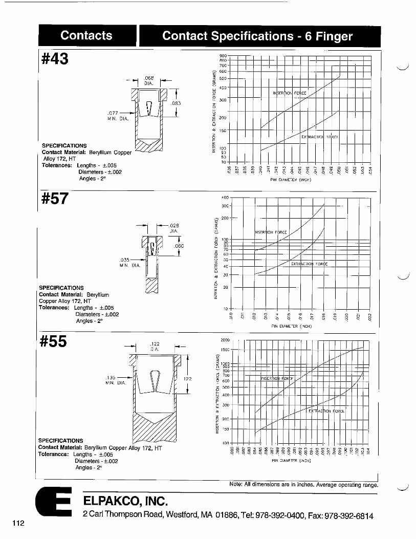
112
Contacts Contact Specifications - 6 Finger
#43 ----1 .068 t--
1 DIA. I
.077 MIN. DIA.
SPECIFICATIONS Contact Material: Beryllium Copper Alloy 172, HT Tolerances: Lengths - ±.005
Diameters - ±.002 Angles - 2°
#57
.083
I
i J--.028 I DIA.
SPECIFICATIONS Contact Material: Beryllium Copper Alloy 172, HT Tolerances: Lengths - ±.005
#55
Diameters - ±.002 Angles - 2°
SPECIFICATIONS
.122 DIA.
Contact Material: Beryllium Copper Alloy 172, HT Tolerances: Lengths - ±.005
Diameters - ±.002 Angles - 2°
ELPAKCO, INC.
7 .060
900 8 00 700
Vi 600
"' 500 -,;
"' 8 400 w u
"' e 300 2 0
" (.) <
200 "' t-X w
"' z 0
" i!'j V1 ~
;;;-::; < "'-s w V "'-0 "-z 0
" () 4:
I?: i:'i
"' z 0
" "' w Vl ~
150
100 90 8 0 70
400
300
200
100 90 80 70 60
50
40
30
20
10
2000
1500
;;;-
! 1000 l.') 900 - 600 ~ 700
2 600
5 500
" u 400 -< 1" ~ .300
8 200
" "' "' tn 150 ;;
100
V
/
IN~ER nON FO CE V V
/ V
/ V /
V V V V
V
V ....
V EX RA< TIOI FOflCE .......
v -
PIN DIAMETER (INCH)
/ V
NSER ION F ~RCE V / V
/
V ./
/ EXm ,CTIO FOR E
----L.----'"
~t"'),q-t()(O ......
~ ~ ~ ~ ~ q PIN DIAMETER ( INCH)
-I/./
v .......
✓
V
IN: ER 10 i I OR E _,.,. /
I/ V V V
/
v v _...v y
vv vv .....-E Tl AC IQ~ OR E vv
vv ..,..
g ~ ~ ~ ~ ~ ::; ~ ~ g, ~ ~ ~ ~ ~ ~ ~ ~ ~ g g O ~ 8 .; q qqoqqo q qq .q q oqqooq~~~~~
PIN DIAMETER (INCH)
Note: All dimensions are in inches. Average operating range.
2 Carl Thompson Road, Westford, MA 01886, Tel: 978-392-0400, Fax: 978-392-6814

Quick Find!! Series & Part Number Index
~ SERIES PAGE PART NO. PAGE PART NO. PAGE PART NO. PAGE PARTNO. PAGE PART NO. PAGE 10 5 4017 49 4095 63 4165 69 4241 79 11 7 4018 50 4096 63 4166 69 4242 79 1S2-23 87 12 9 4019 50 4097 63 4167 69 4243 79 1S3-24 87 13 14 4020 50 4098 63 4168 69 4244 79 14 15 4021 50 4099 63 4169 70 4245 80 1P4-26 87
4022 50 4100 63 4170 70 4246 80 1$6-27 87 18 25 4023 50 4101 63 4172 70 4247 80 2D6-29 88 19 26 4025 51 4102 63 4173 70 4248 80 206-30 88 20 27 4026 51 4103 54 4174 70 4249 80 21 28 4027 51 4104 54 4175 71 4250 82 2D6-31 88
22 28 4028 51 4105 54 4176 71 4251 82 2D6-32 88
38 37 4030 51 4106 54 4177 71 4252 82 205-33 88
10C 6 4031 51 4107 54 4178 71 4253 82 2S6-34 88
10E 5 4033 51 4108 54 4179 71 4254 82 2S5-35 88
11A 8 4034 53 4109 54 4180 71 4255 82 25S-36 88
4041 53 4110 54 4181 71 4256 82 2S5-37 89
4042 53 4111 54 4182 71 4257 82 2S4-38 89
12CW 13 4043 53 4115 56 4183 72 4258 82 2S4-39 89
12D 9 4044 53 4116 56 4184 72 4259 82 2S3-40 89
12E 9 4045 53 4117 56 4185 72 4260 82 3D010-41 89
12F 9 4046 52 4118 60 4186 73 4261 82 3D08-42 89
15A 18 4047 52 4119 60 4187 73 4262 83 30D8-43 89
15AE 18 4048 52 4120 60 4188 72 4263 83 3KD8-44 89
15E 16 4049 55 4121 64 4189 73 4264 83 30D6-45 90 15P 16 4050 55 4122 64 4190 74 4265 83 3D05-46 90 18B 25 4051 55 4123 64 4191 74 4266 83 3KDD5-47 90 20B 27 4052 55 4124 64 4192 74 4267 83 30D4-48 90 21D 28 4053 55 4125 64 4193 72 4268 83 22D 28 4054 55 4126 64 4194 74 4269 83 3D03-49 90
4055 55 4127 64 4195 75 4270 83 3PD8-50 90
MSA 34 4056 56 4129 65 4196 75 4271 57 3PD5-51 90
PH 35 4057 57 4130 65 4197 75 4275 51 3PD5-52 90
4058 57 4131 67 4198 75 4276 61 30S8-53 90
RA 31 4059 57 4132 65 4199 72 4277 82 30S8-54 91
4061 57 4133 65 4200 76 4278 52 3DS6-56 91
SD 26 4063 58 4134 65 4201 76 4280 52 30S4-57 91
SMC 29 4064 58 4135 65 4202 76 4281 46 3DS3-58 91
SW1 40 4065 58 4136 65 4203 76 4282 56 3SP3-59 91
TO 8 4066 58 4137 81 4204 76 4283 83 3SP2-60 91
ll. 30 4067 58 4138 81 4205 76 4284 83 3S810-61 91
PART NO. PAGE 4071 58 4139 81 4213 76 4286 41 3S88-62 91
12 45 4072 58 4140 81 4214 76 3SS3-63 92
1D6-1 85 3S85-64 92 98 45 4073 59 4141 81 4215 76
85 38S4-65 92 99 45 4074 59 4142 81 4216 76 1KD6-2 3PP4-66 92
1066 64 4075 59 4143 81 4217 76 1FKD6-3 85 38S3-67 92
1078 48 4076 59 4144 81 4218 76 105-4 85 38S5-68 92
2006 60 4077 59 4145 67 4219 76 105-5 85 4S8-69 92
2220 45 4078 59 4146 67 4220 76 1D4-6 85 4S8-70 92
4000 47 4079 59 4147 67 4221 76 1KD4-7 85 4S8-71 92
4001 47 4080 59 4148 67 4222 77 103-8 85 4S7-72 93
4002 47 4081 59 4149 67 4223 77 1KD3-9 85 4S7-73 93
4003 47 4082 60 4150 67 4224 76 103-10 86 4S6-74 93
4004 47 4083 60 4153 68 4225 75 103-11 86 4S6-75 93
4005 47 4084 61 4154 67 4226 75 1T6-12 86 4S5-76 93
4006 47 4085 61 4155 68 4227 75 1T4-13 86 4S5-77 93 4S3-78 93
4007 47 4086 61 4156 68 4228 75 1T6-14 86 4D5-79 93 4008 48 4087 61 4157 68 4229 78 106-15 86 4D5-80 93 4010 48 4088 61 4158 68 4230 78 1D6-16 86 52S6-81 94 4011 48 4089 62 4159 68 4231 78 1S6-17 86 5S6-82 94 4012 48 4090 62 4160 68 4232 78 1KS6-18 86 52S6-83 94 4013 48 4091 62 4161 69 4237 79 1S4-19 87 5S26-84 94 4014 49 4092 62 4162 69 4238 79 1KS4-20 87 5S4-85 94
4015 50 4093 62 4163 69 4239 79 1S3-21 87 5S4-86 94
(', 4016 49 4094 62 4164 69 4240 79 5D4-88 94
ELPAKCO, INC. 2 Carl Thompson Road, Westford, MA 01886, Tel: 978-392-0400, Fax: 978-392-6814
113

Quick Find!! Series & Part Number Index PART NO. PAGE PART NO. PAGE CONTACT PAGE
206-129 95 CONTACT PAGE 2S4-139 95 30 106 4S3-178 95 32 106 4S3-278 95 33 109 82S 38 34 110 E0250 39 36 108 E0350 39 40 109 E0600 39 41 109 E2871 40 42 108 E2872 40 43 112 E3360 40 45 110 E3771 40 46 110 FT03 43 48 111 FT04 44 51 106 FT05 44 52 108 FT06 42 53 111 MP-125 104 54 111 MP-130 104 55 112 MP-135 104 56 107 MP-140 104 57 112 MP-160 104 MP-162 104 MP-165 104 MP-166 104 MP-170 104 MP-172 104 MP-175 104 MP-200 104 MP-205 104 MP-230 104 MP-235 104 MP-260 105 MP-265 105 MP-290 105 MP-315 105 SEO? 42 SE08 43 SP1 38 SP2 38 SP3 38
ELPAKCO, INC. 114
2 Carl Thompson Road, Westford, MA 01886, Tel: 978-392-0400, Fax: 978-392-6814
