lms12x/lms13x/lms14x security laser measurement sensors
TRANSCRIPT

Technical information
Laser Measurement Sensors LMS1xx Security
8014487/13Z4/2019-12-02 © SICK AG · Germany · All rights reserved · Subject to change without notice 1
Chapter
LMS12x/LMS13x/LMS14x SecurityLaser Measurement Sensors
Integrator Commissioning Description Security.Supplement to the operating instructions of LMS1xx product family.Valid for commissioning according to Security Applications.
T E C H N I C A L I N F O R M AT I O N

Technical information
Laser Measurement Sensors LMS1xx Security
Chapter
Described product
LMS12x Security IndoorLMS13x/LMS14x Security Outdoor
LMC12x VdS IndoorLMC13x VdS Semi Outdoor
Manufacturer
SICK AGErwin-Sick-Str. 179183 WaldkirchGermany
Copyright
This work is protected by copyright. Any rights derived from the copyright shall be reserved for SICK AG. Reproduction of this document or parts of this document is only permissible within the limits of the legal determination of Copyright Law. Any modification, expurgation or translation of this document is prohibited without the express written permission of SICK AG.
© SICK AG. All rights reserved.
Original document
This document is an original document of SICK AG.
2 © SICK AG · Germany · All rights reserved · Subject to change without notice 8014487/13Z4/2019-12-02

Technical information
Laser Measurement Sensors LMS1xx Security
Chapter
Table of contents
1 About this document .......................................................................................................51.1 Information regarding the Technical Information ..................................................... 51.2 Traget group ................................................................................................................ 51.3 Scope ........................................................................................................................... 51.4 Depth of information ................................................................................................... 71.5 Explanation of symbols ............................................................................................... 71.6 Further information ..................................................................................................... 81.7 Customer service ........................................................................................................ 92 For your safety ..............................................................................................................112.1 Correct use ................................................................................................................ 112.2 Incorrect use .............................................................................................................. 112.3 Hazard warnings and operational safety ................................................................. 123 Getting started with the LMS1xx Security/LMC1xx VdS ......................................... 153.1 Connection buildup ................................................................................................... 153.2 Configuration ............................................................................................................. 164 Product description ...................................................................................................... 174.1 Typical application ..................................................................................................... 174.2 Delivery ...................................................................................................................... 174.3 Device variants .......................................................................................................... 194.4 Special features ........................................................................................................ 224.5 Basic parameters for the measurement of objects ................................................ 234.6 Field application ........................................................................................................ 254.7 VdS-compliant construction ..................................................................................... 275 Mounting ........................................................................................................................ 295.1 Sealing the LMC12x/LMC13x .................................................................................. 295.2 Mounting the VdS mounting kit ................................................................................ 296 Electrical installation ................................................................................................... 316.1 Planning and preparation ......................................................................................... 316.2 Hints for compliance with enclosure rating ............................................................. 326.3 Indoor variants: LMS12x Security/LMC12x VdS connections ............................... 336.4 Outdoor/semi-outdoor variants: Connections of the LMS13x/LMS14x Security and
LMC13x VdS .............................................................................................................. 356.5 Wiring the outputs on the LMS1xx Security/LMC1xx VdS ...................................... 386.6 Wire cross-sections ................................................................................................... 397 Commissioning and configuration ............................................................................. 417.1 Configuration (parameterization) ............................................................................. 417.2 Obstruction protection .............................................................................................. 457.3 Validity check ............................................................................................................. 487.4 EasyTeach .................................................................................................................. 497.5 Automatic Field Adaption ......................................................................................... 557.6 Contamination measurement .................................................................................. 567.7 Additional settings for the LMS12x/LMS13x/LMS14x Security ............................ 568 Maintenance ................................................................................................................. 578.1 Maintenance during operation ................................................................................. 578.2 Exchanging an LMS1xx Security/LMC1xx VdS ........................................................ 588.3 Troubleshooting .........................................................................................................61
8014487/13Z4/2019-12-02 © SICK AG · Germany · All rights reserved · Subject to change without notice 3

Technical information
Laser Measurement Sensors LMS1xx Security
Chapter
9 Technical specifications .............................................................................................. 639.1 Data sheet LMS12x/LMS13x/LMS14x Security and
LMC12x/LMC13x VdS laser measurement sensors .............................................. 639.2 Operating range diagrams ....................................................................................... 699.3 Dimensional drawings .............................................................................................. 7010 Annex ............................................................................................................................. 7510.1 Ordering information ................................................................................................ 7510.2 EU declaration of conformity, VdS certificate, other certificates ........................... 7810.3 Glossary ..................................................................................................................... 7910.4 Abbreviations ............................................................................................................ 8010.5 Figures ....................................................................................................................... 8110.6 Tables ........................................................................................................................ 83
4 © SICK AG · Germany · All rights reserved · Subject to change without notice 8014487/13Z4/2019-12-02

About this documentTechnical information
Laser Measurement Sensors LMS1xx Security
Chapter 1
1 About this document
1.1 Information regarding the Technical Information
This technical information as a supplement to the "LMS1xx Laser Measurement Sensors" operating instructions provides important information on how to handle laser measurement sensors from SICK AG.
Prerequisites for working safely are:
Adherence to all the specified safety instructions and guidelines
Complying with any local work safety regulations and general safety specifications applicable to the use of the laser measurement sensors.
The technical information is intended for specialists and electricians.
Important Read both documents, the supplemental technical information and the operating instructions, carefully before starting any work on the device. So you can familiarize yourself quickly with the LMS1xx Security laser measurement sensor or the LMC1xx VdS laser measurement sensor (certified VdS variant) and its functions.
The technical information and the operating instructions are considered a part of the device. Should the device be passed on to a third party, both documents should be handed over with it.
1.2 Traget group
The target group of this document is persons assigned the following tasks:
LMS1xx Security: For the not VdS compliant installation and commissioning qualified electrical specialists.
LMC1xx VdS:For the VdS compliant installation and commissioning only installers and integrators which were verifiable be approved to VdS.
1.3 Scope
The technical information, used as Integrator Instructions Manual, is designed to address the technical personnel in regards to safe mounting, electrical installation, commissioning and configuration and maintenance of the LMS1xx Security laser measurement sensor Security or the LMC1xx VdS certified laser measurement sensor.A step-by-setp approach is taken for all tasks.
8014487/13Z4/2019-12-02 © SICK AG · Germany · All rights reserved · Subject to change without notice 5
About this document Technical information
Laser Measurement Sensors LMS1xx Security
Chapter 1
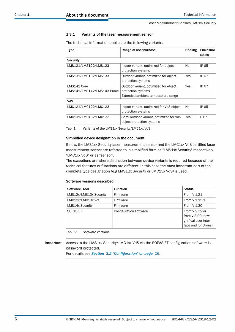
1.3.1 Variants of the laser measurement sensor
The technical information applies to the following variants:
Simplified device designation in the document
Below, the LMS1xx Security laser measurement sensor and the LMC1xx VdS certified laser measurement sensor are referred to in simplified form as "LMS1xx Security" respectively "LMC1xx VdS" or as "sensor". The exceptions are where distinction between device variants is required because of the technical features or functions are different. In this case the most important part of the complete type designation (e.g LMS12x Security or LMC13x VdS) is used.
Software versions described
Important Access to the LMS1xx Security/LMC1xx VdS via the SOPAS ET configuration software is password protected. For details see Section 3.2 “Configuration” on page 16.
Type Range of use/purpose Heaiing Enclosurerating
Security
LMS121/LMS122/LMS123 Indoor variant, optimized for object protection systems
No IP 65
LMS131/LMS132/LMS133 Outdoor variant, optimized for object protection systems
Yes IP 67
LMS141 CoreLMS141/LMS142/LMS143 Prime
Outdoor variant, optimized for object protection systems.Extended ambient temperature range
Yes IP 67
VdS
LMC121/LMC122/LMC123 Indoor variant, optimized for VdS object protection systems
No IP 65
LMC131/LMC132/LMC133 Semi outdoor variant, optimized for VdS object protection systems
Yes P 67
Tab. 1: Variants of the LMS1xx Security/LMC1xx VdS
Software/Tool Function Status
LMS12x/LMS13x Security Firmware From V 1.21
LMC12x/LMC13x VdS Firmware From V 1.15.1
LMS14x Security Firmware From V 1.30
SOPAS ET Configuration software From V 2.32 orfrom V 3.00 (new grafical user inter-face and functions)
Tab. 2: Software versions
6 © SICK AG · Germany · All rights reserved · Subject to change without notice 8014487/13Z4/2019-12-02

About this documentTechnical information
Laser Measurement Sensors LMS1xx Security
Chapter 1
1.4 Depth of information
This technical information is based on the "LMS1xx Laser Measurement Sensors“ operating instructions (part no. 8012471, English version).
These installer instructions are limited to the information necessary for VdS-compliant installation or a security installation.
For the certified sensors LMC12x/LMC13x Vds the installer instructions describe the VdS requirements and implemented test methods.
They contain the following information on the LMS1xx Security/LMC1xx VdS:
Product description
Mounting
Electrical installation
Commissioning and configuration
Ordering information
For inital information, typespecific Notes on Device with the connection diagrams are also included with the devices:
Notes on Device "LMS12x Security Indoor/LMC12x VdS Indoor" (part. no. 8013554, German/English version)
Notes on Device "LMS13x/LMS14x Security Outdoor/LMC13x VdS Semi Outdoor" (part. no. 8013727, German/English version)
1.5 Explanation of symbols
Warnings in this technical information are indicated by symbols. The warnings are introducedby signal words that indicate the extent of the danger.
These warnings must be observed at all times and care must be taken to avoid accidents, personal injury, and material damage.
... indicates a situation of imminent danger, which will lead to a fatality or serious injuries if not prevented.
… indicates a potentially dangerous situation, which may lead to a fatality or serious injuries if not prevented.
.… indicates a potentially dangerous situation, which may lead to minor/slight injuries if not prevented.
8014487/13Z4/2019-12-02 © SICK AG · Germany · All rights reserved · Subject to change without notice 7

About this document Technical information
Laser Measurement Sensors LMS1xx Security
Chapter 1
… indicates a potentially harmful situation, which may lead to material damage if not prevented.
Important … highlights useful tips and recommendations as well as information for efficient and trouble-free operation.
Recommendation Recommendations are designed to give you assistance in the decision-making process with respect to a certain function or a technical measure.
Important Sections marked “Important” provide information about special features of the device.
Explanation Explanations provide background knowledge on technical relationships.
MENU COMMAND This typeface indicates a term in the SOPAS ET user interface.
Terminal output This typeface indicates messages that the LMS1xx Security/LMC1xx VdS outputs via its interfaces.
Take action … Here you must do something. This symbol indicates an instruction to perform an action that contains only one action or actions in warnings where a specific sequence does not need to be followed. Instructions to perform actions that contain several steps in sequence are numbered.
This symbol refers to additionally available documentation.
Software notes show where you can make the appropriate settings and adjustments in the SOPAS ET configuration software.
1.6 Further information
LMS12x/LMS13x/LMS14x Security
Important All the documentation available can be found on the online product page at:
http://www.sick.com/en/lms1xx
The following information is available for download there:
Model-specific online data sheets for device variants, containing technical data, dimensional drawings, and operating range diagrams
Certificates of the product family
Dimensional drawings and 3D CAD dimension models in various electronic formats
Operating range diagrams
“LMS1xx laser measurement sensors“ operating instructions. In English (part no. 8012471) and German (part no. 8012470), and other languages (if applicable)
“Laser Measurement Sensor” telegram listing, in English (part no. 8014631)
8 © SICK AG · Germany · All rights reserved · Subject to change without notice 8014487/13Z4/2019-12-02

About this documentTechnical information
Laser Measurement Sensors LMS1xx Security
Chapter 1
"Laser Measurement Systems of the LMS100 Product Family" product information in English (part no. 8012468) and German (part no. 8012467), and other languages (if applicable)
Publications dealing with accessories
LMC12x/LMC13x VdS
Important All the documentation available can be found on the online product page at:
http://www.sick.com/en/lmc1xx
The following information is available for download there:
Model-specific online data sheets for device variants, containing technical data, dimensional drawings, and operating range diagrams
Certificates of the product family
Dimensional drawings and 3D CAD dimension models in various electronic formats
Operating range diagrams
“LMS1xx laser measurement sensors“ operating instructions. In English (part no. 8012471) and German (part no. 8012470), and other languages (if applicable)
“LMS12x/LMS13x/LMS14x Security“ technical information (installer instructions) as supplement to the operating instructions. In English (part no. 8014487) and German(part no. 8014486), and other languages (if applicable)
“LMS12x/LMS13x/LMS14x Security and LMC12x/LMC13x VdS“ technical information (installer instructions VdS) as supplement to the operating instructions. In English (part no. 8013749) and German (part no. 8013748), and other languages (if applicable)
“Laser Measurement Sensor” telegram listing, in English (part no. 8014631)
"Laser Measurement Systems of the LMS100 Product Family" product information in English (part no. 8012468) and German (part no. 8012467), and other languages (if applicable)
1.7 Customer service
Do not hesitate to contact our customer service should you require any technical information. Please refer to the back page of these operating instructions for your agent's contact details.
Important Before calling, make a note of all type label data such as type code, serial number, etc. to ensure faster processing.
8014487/13Z4/2019-12-02 © SICK AG · Germany · All rights reserved · Subject to change without notice 9

About this document Technical information
Laser Measurement Sensors LMS1xx Security
Chapter 1
10 © SICK AG · Germany · All rights reserved · Subject to change without notice 8014487/13Z4/2019-12-02

For your safetyTechnical information
Laser Measurement Sensors LMS1xx Security
Chapter 2
2 For your safety
This chapter deals with your own safety and the safety of the equipment operators.
Please read this chapter carefully before working with the LMS1xx Security/LMC1xx VdS.
This technical information is based on the "LMS1xx Laser Measurement Sensors“ operating instructions (part no. 8012471, English version).
Follow all notes and warnings in the operating instructions on which these instructions are based as well as the notes and warnings in this technical information!
2.1 Correct use
The LMS1xx Security and LMC1xx VdS sensors are non-contact optical distance measurement sensor for stand-alone or network operation. They are suitable for applications in which precise, electro-sensitive measurements of contours and surroundings are required. It is also possible to create systems, for instance, for collision protection, for building surveillance or for access monitoring.
The sensors must be initialized only by qualified personnel.
Important The sensors are only allowed to be operated in the ambient temperature range allowed (see Section 9.1 “Data sheet LMS12x/LMS13x/LMS14x Security and LMC12x/LMC13x VdS laser measurement sensors” on page 63).
2.2 Incorrect use
The LMS1xx Security and LMC1xx VdS sensors do not constitute a safety component as defined in the relevant applicable safety standards for machines.
The LMS1xx Security and LMC1xx VdS sensors must not be used in explosion hazard areas.
Any other use that is not described as correct use is prohibited.
The use of accessories not specifically approved by SICK is at own risk.
8014487/13Z4/2019-12-02 © SICK AG · Germany · All rights reserved · Subject to change without notice 11

For your safety Technical information
Laser Measurement Sensors LMS1xx Security
Chapter 2
2.3 Hazard warnings and operational safety
2.3.1 Laser radiation
The LMS1xx Security/LMC1xx VdS operates with a infrared-light laser diode. The laser beam cannot be seen with the human eye.
Laser radiation!
The LMS1xx Security/LMC1xx VdS corresponds to laser class 1 (eye safe) as per EN 60 8251:2014. Identical laser class for issue EN/IEC 60825-1:2007Complies with 21 CFR 1040.10 with the exception of the deviations as per Laser Notice No. 50, Juin, 2007.
Incorrect usage can result in hazardous exposure to laser radiation.
Do not open the housing (opening the housing will not switch off the laser).
Pay attention to the laser safety regulations as per IEC 60 8251 (latest version).
Caution – Use of controls or adjustments or performance of procedures other than those specified herein may result in hazardous radiation exposure.
It is not possible to entirely rule out temporary disorienting optical effects, particularly in conditions of dim lighting. Disorienting optical effects may come in the form of dazzle, flash blindness, afterimages, photosensitive epilepsy, or impairment of color vision, for example.
Important No maintenance is necessary to ensure compliance with laser class 1.
Laser power
The laser operates at a wavelength = 905 nm (invisible infrared light). The radiation emitted in normal, appropriate operation is not harmful to the eyes and human skin.
Laser output aperture
The laser output aperture is the window of the optics cover on the LMS1xx Security/LMC1xx VdS.
Window of the optics cover
12 © SICK AG · Germany · All rights reserved · Subject to change without notice 8014487/13Z4/2019-12-02

For your safetyTechnical information
Laser Measurement Sensors LMS1xx Security
Chapter 2
2.3.2 Electrical installation work
Only authorized specialists are allowed to perform the skilled electrical installation work.
Only make and disconnect electrical connections when the device is electrically isolated.
Select and implement wire cross-sections and their correct fuse protection as per the applicable standards.
Do not open the housing.
Observe the current safety regulations when working on electrical systems.
Fig. 1: Laser output aperture
8014487/13Z4/2019-12-02 © SICK AG · Germany · All rights reserved · Subject to change without notice 13

For your safety Technical information
Laser Measurement Sensors LMS1xx Security
Chapter 2
14 © SICK AG · Germany · All rights reserved · Subject to change without notice 8014487/13Z4/2019-12-02
Getting started with the LMS1xx Security/LMC1xx VdSTechnical information
Laser Measurement Sensors LMS1xx Security
Chapter 3
3 Getting started with the LMS1xx Security/LMC1xx VdS
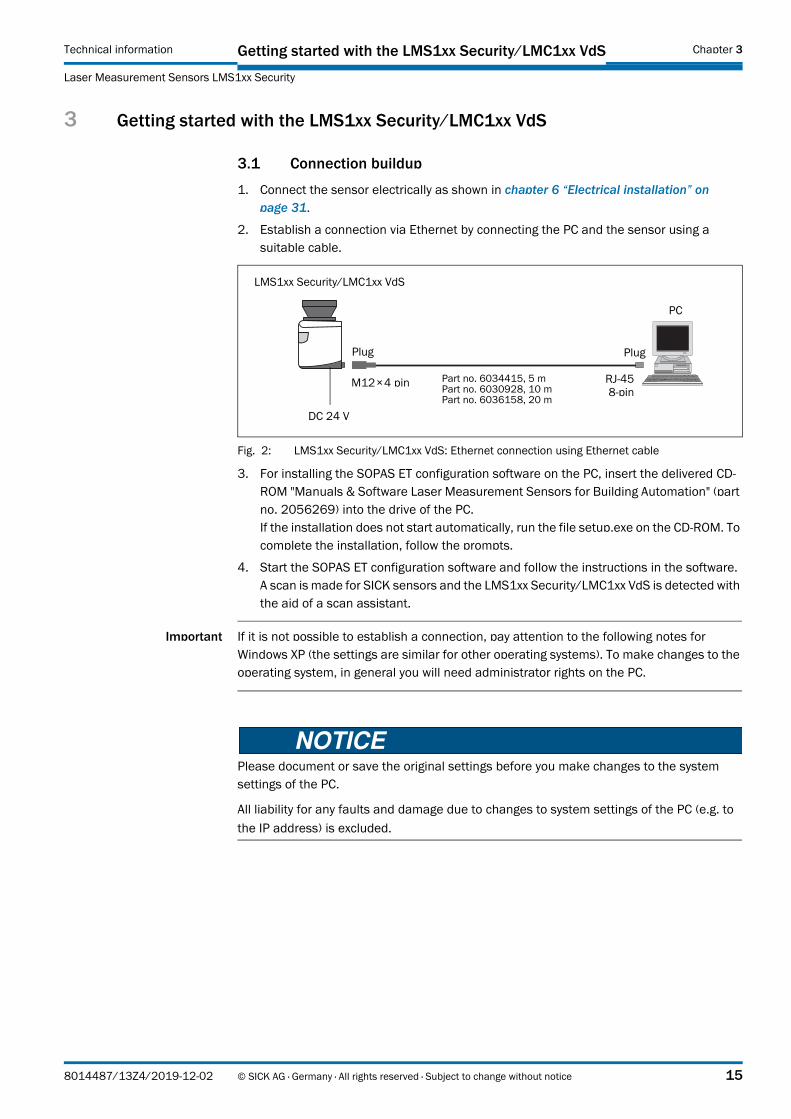
3.1 Connection buildup
1. Connect the sensor electrically as shown in chapter 6 “Electrical installation” on page 31.
2. Establish a connection via Ethernet by connecting the PC and the sensor using a suitable cable.
Fig. 2: LMS1xx Security/LMC1xx VdS: Ethernet connection using Ethernet cable
3. For installing the SOPAS ET configuration software on the PC, insert the delivered CD-ROM "Manuals & Software Laser Measurement Sensors for Building Automation" (part no. 2056269) into the drive of the PC. If the installation does not start automatically, run the file setup.exe on the CD-ROM. To complete the installation, follow the prompts.
4. Start the SOPAS ET configuration software and follow the instructions in the software. A scan is made for SICK sensors and the LMS1xx Security/LMC1xx VdS is detected with the aid of a scan assistant.
Important If it is not possible to establish a connection, pay attention to the following notes for Windows XP (the settings are similar for other operating systems). To make changes to the operating system, in general you will need administrator rights on the PC.
Please document or save the original settings before you make changes to the system settings of the PC.
All liability for any faults and damage due to changes to system settings of the PC (e.g. to
the IP address) is excluded.
LMS1xx Security/LMC1xx VdS
DC 24 V
M12 × 4 pin RJ-45 8-pin
Plug
Part no. 6034415, 5 mPart no. 6030928, 10 mPart no. 6036158, 20 m
Plug
PC
8014487/13Z4/2019-12-02 © SICK AG · Germany · All rights reserved · Subject to change without notice 15

Getting started with the LMS1xx Security/LMC1xx VdS Technical information
Laser Measurement Sensors LMS1xx Security
Chapter 3
Ensure that any “Secure Clients” etc. on your PC/notebook that monitor access are deactivated while the parameters are configured. Check the settings using the START MENU, SETTINGS, NETWORK CONNECTIONS, LOCAL AREA CONNECTION. In the LOCAL AREA CONNECTION STATUS dialog box click PROPERTIES.
Fig. 3: Local Area Connection Properties in Windows XP
Ensure that the IP address of your PC/notebook is correct. LMS1xx Security/LMC1xx VdS and notebook must not have the same IP address.
Fig. 4: IP address in Windows XP
Proxy servers should be disabled or an exception entered for the IP address.
3.2 Configuration
Once the scan assistant has detected the LMS1xx Security/LMC1xx VdS , add the device to a new project.
Logon to configure the parameters on the device. Software access is password protected. In the default delivery status the following passwords are defined:
Make the necessary settings on the LMS1xx Security/LMC1xx VdS on the QUICK-START page in SOPAS ET (for the LMS1xx Security you can also configure the device in the Expert mode).
Setup at least one monitoring field and one monitoring case.
Connect the outputs electrically to the object protection systems as shown in chapter 6 “Electrical installation” on page 31.
User level Password
Operator –
Operator (maintenance personnel) main
Integrator (authorized client) client
Tab. 3: Passwords for LMS1xx Security/LMC1xx VdS
16 © SICK AG · Germany · All rights reserved · Subject to change without notice 8014487/13Z4/2019-12-02

Product descriptionTechnical information
Laser Measurement Sensors LMS1xx Security
Chapter 4
4 Product description
This chapter provides information on the special features and properties of the LMS1xx Security/LMC1xx VdS sensor. It describes the construction and the operating principle of the device. Please read this chapter before mounting, installing and commissioning the device.
4.1 Typical application
The LMS1xx Security/LMC1xx VdS are particularly suitable for use as curtain detectors by using them in front of the objects to be protected, or as intrusion detectors for walls and windows.
They can be used type-dependently indoors and outdoors for the vertical monitoring of fence systems or for the horizontal monitoring of flat open areas such as lawns, courtyards, paths and drives. They are also suitable for monitoring roofs and ceilings.
People or objects who enter the detection range of the sensor will be reliably detected. Interruptions with or without tools are also detected independent of the distance, as are climbing over or climbing through. The sensor also accurately detects people who are walking, running, crawling over an area, or vehicles that are driving over an area.
4.2 Delivery
4.2.1 LMS12x, LMS13x and LMS14x Security
The delivery includes the following components for one sensor:
Quantity Components Comment
1 LMS1xx Security laser measurement sensor
Model type depends on order.
Outdoor variants: M12-round plug-in connectors equipped with protection caps and plugs made of plastic
5 Sealing strips Hardware, self-adhesive
1 Printed safety notes, multilingual Short information and general safety notes
1 "Manuals & Software Laser Measure-ment Sensors for Building Automation" CD-ROM (part no. 2056269), from isssue Stand YIA3.
Content:SOPAS ET configuration softwareProduct literature LMS1xx/LMC1xx
Tab. 4: Items supplied LMS12x, LMS13x and LMS14x Security
8014487/13Z4/2019-12-02 © SICK AG · Germany · All rights reserved · Subject to change without notice 17

Product description Technical information
Laser Measurement Sensors LMS1xx Security
Chapter 4
4.2.2 LMC12x und LMC13x VdS
The delivery includes the following components for one sensor:
Section 10.1 “Ordering information” on page 75 provides an overview of the systems available and the accessories available.
Quantity Components Comment
1 LMC1xx VdS laser measurement sensor
Model type depends on order.
Outdoor variants: M12-round plug-in connectors equipped with protection caps and plugs made of plastic.
In conjunction with the VdS mounting kit, either LMC12x or LMC13x, depending on the order
1 VdS mounting kit Hardware, depending on order
5 Sealing strips Hardware, self-adhesive
1 Additional typeplate for ordered LMC1xx VdS
Is used for substituted device marking on VdS mounting kit.
1 Type-specific notes on device with electrical circuit diagram for getting started (part no. 8013727)
Is included in the LMC1xx packaging
1 "Manuals & Software Laser Measure-ment Sensors for Building Automation" CD-ROM (part no. 2056269), from isssue Stand YIA3.
Content:SOPAS ET configuration softwareProduct literature LMS1xx/LMC1xx (Product informations, operating instructions, technical information)
Tab. 5: Items supplied LMC12x /LMC13x VdS
18 © SICK AG · Germany · All rights reserved · Subject to change without notice 8014487/13Z4/2019-12-02

Product descriptionTechnical information
Laser Measurement Sensors LMS1xx Security
Chapter 4
4.3 Device variants
Indoor Ambient temperature range 0 °C to +50 °C, no fog filter or particle filter activated as factory default setting
Outdoor Ambient temperature range –30 °C to +50 °C, LMS14x Prime/Core Security: –40 °C to +60 °C, fog filter and particle filter are activated as factory default setting
Semi-outdoor Ambient temperature range –30 °C to +50 °C, fog filter is activated as factory default setting, the particle filter is not activated, in accordance with VdS photoelectric switch guidelines can be set to no multiple sampling (class C) or double multiple sampling (class B).
LMC12x/LMC13x VdS
The certified sensors are based on the following VdS guidelines:
2117 requirement (photoelectric switches = LS) in accordance with test method VdS 2485
2312 requirement (movement detectors = BM) in accordance with test method VdS 2326
The test was made …
for LMC12x as per photoelectric switches class C environment class II (indoor),
for LMC13x as per photoelectric switches class C environment class IVa (outdoor).
The variant LMC12x has the VdS approval number G110045.
The variant LMC13x has the VdS approval number G111032.
The devices are suitable for usage in intrusion detection systems as per EN 50 131-1. The devices are suitable as per VdS guidelines for monitoring access to easy-to-enter areas from up to 18 m.
Type Range of use/purpose Heating Enclosure rating
Security
LMS121/LMS122/LMS123 Indoor variant, optimized for object protection systems
No IP 65
LMS131/LMS132/LMS133 Outdoor variant, optimized for object protection systems
Yes IP 67 1)
1) Under the following conditions: the cables plugged into the M12 round plug-in connections must be screwed tight. Any electrical connections that are not being used must be fitted with protective caps or plugs that are screwed tight (as in the delivery condition). The M8 connection on the front is screwed tight
LMS141 CoreLMS141/LMS142/LMS143 Prime
Outdoor variant, optimized for object protection systems.Extended ambient temperature range
Yes IP 67 1)
VdS
LMC121/LMC122/LMC123 Indoor variant, optimized for VdS object protection systems
No IP 65
LMC131/LMC132/LMC133 Semi outdoor variant, optimized for VdS object protection systems
Yes P 67 1)
Tab. 6: Variants of LMS1xx Security/LMC1xx VdS
8014487/13Z4/2019-12-02 © SICK AG · Germany · All rights reserved · Subject to change without notice 19

Product description Technical information
Laser Measurement Sensors LMS1xx Security
Chapter 4
Important The LMC12x/LMC13x have a firmware status that has been approved and documented by the VdS.
VdS-compliant installation of the LMC1xx is only possible using the VdS mounting kit.
For VdS-compliant installation of the LMC1xx the related VdS guidelines, e.g. on planning and installation, are to be followed.
4.3.1 LMS12x Security Indoor
4.3.2 LMS13x Security Outdoor
Type Special feature Part no.
LMS121-10000 Security Laser measurement sensor, indoor variantOperating ambient temperature: 0°C ... 50°CHousing color: pebble gray (RAL7032)
1051384
LMS122-10000 Security Laser measurement sensor, indoor variantOperating ambient temperature: 0°C ... 50°CHousing color: jet black (RAL9005)
1044322
LMS123-10000 Security Laser measurement sensor, indoor variantOperating ambient temperature: 0°C ... 50°CHousing color: signal white (RAL9003)
1044321
Tab. 7: Variants of the LMS12x Security Indoor
Type Special feature Part no.
LMS131-10100 Security Laser measurement sensor, Outdoor variantOperating ambient temperature: –30°C ... +50°CHousing color: pebble gray (RAL7032)
1051379
LMS132-10100 Security Laser measurement sensor, Outdoor variantOperating ambient temperature: –30°C ... +50°CHousing color: jet black (RAL9005)
1051402
LMS133-10100 Security Laser measurement sensor, Outdoor variantOperating ambient temperature: –30°C ... +50°CHousing color: signal white (RAL9003)
1051403
Tab. 8: Variants of the LMS13x Security Outdoor
20 © SICK AG · Germany · All rights reserved · Subject to change without notice 8014487/13Z4/2019-12-02

Product descriptionTechnical information
Laser Measurement Sensors LMS1xx Security
Chapter 4
4.3.3 LMS14x Security Outdoor
4.3.4 LMC12x VdS Indoor
Type Special feature Part no.
LMS141-05100 Core Security
Laser measurement sensor, outdoor variantOperating ambient temperature: –40°C ... +60°CHousing color: pebble gray (RAL7032)
1070209
LMS141-15100 PrimeSecurity
Laser measurement sensor, outdoor variantOperating ambient temperature: –40°C ... +60°CHousing color: pebble gray (RAL7032)
1070409
LMS142-15100 Prime Security
Laser measurement sensor, outdoor variantOperating ambient temperature: –40°C ... +60°CHousing color: jet black (RAL9005)
1070410
LMS143-15100 Prime Security
Laser measurement sensor, outdoor variantOperating ambient temperature: –40°C ... +60°CHousing color: signal white (RAL9003)
1070411
Tab. 9: Variants of the LMS14x Security Outdoor
Type Special feature Part no.
LMC121-11000 - VdS Laser measurement sensor certified, indoor variantVdS mounting kit 1 — longOperating ambient temperature: 0°C ... +45°CHousing color: pebble gray (RAL7032)
1051287
LMC121-11001 - VdS Laser measurement sensor certified, indoor variantVdS mounting kit 2 — shortOperating ambient temperature: 0°C ... +50°CHousing color: pebble gray (RAL7032)
1051314
LMC122-11000 - VdS Laser measurement sensor certified, indoor variantVdS mounting kit 1 — longOperating ambient temperature: 0°C ... +45°CHousing color: jet black (RAL9005)
1051300
LMC122-11001 - VdS Laser measurement sensor certified, indoor variantVdS mounting kit 2 — shortOperating ambient temperature: 0°C ... +50°CHousing color: jet black (RAL9005)
1051315
LMC123-11000 - VdS Laser measurement sensor certified, indoor variantVdS mounting kit 1 — longOperating ambient temperature: 0°C ... +45°CHousing color: signal white (RAL9003)
1051301
LMC123-11001 - VdS Laser measurement sensor certified, indoor variantVdS mounting kit 2 — shortOperating ambient temperature: 0°C ... +50°CHousing color: signal white (RAL9003)
1051316
LMC124-11000 - VdS Laser measurement sensor certified, indoor variantHousing color: jet black (RAL9005)VdS mounting kit 1 — longcolor: uncoated aluminiumOperating ambient temperature: 0°C ... +45°C
1051303
Tab. 10: Variants of the LMC12x Vds Indoor
8014487/13Z4/2019-12-02 © SICK AG · Germany · All rights reserved · Subject to change without notice 21

Product description Technical information
Laser Measurement Sensors LMS1xx Security
Chapter 4
4.3.5 LMC13x VdS (Semi-Outdoor1))
4.4 Special features
Field of view: 270°
Angular resolution: 0.25°/0.5°
Scanning frequency: 25 Hz/50 Hz
Interface: RS-232/Ethernet/OPC
2 relay outputs (alarm, fault) + 1 sabotage output
Supply voltage: LMS12x Security/LMC12x VdS: DC 9 V to 30 VLMS13x Security/LMC13x VdS: sensor: DC 9 V to 30 V, heating: DC 24 V ± 20 %LMS14x Security: sensor: DC 9 V to 30 V, heating: DC 24 V –10 %/+20 %
Enclosure rating::LMS12x Security and LMC12x VdS: IP 65LMS13x/LMS14x Security and LMC13x VdS: IP 67
Type Special feature Part no.
LMC131-11101 - VdS Laser measurement sensor certified, semi outdoor variantVdS mounting kit 2 — shortOperating ambient temperature: –30°C ... +50°CGehäusefarbe: pebble gray (RAL7032)
1051487
LMC132-11101 - VdS Laser measurement sensor certified, semi outdoor variantVdS mounting kit 2 — shortOperating ambient temperature: –30°C ... +50°CHousing color: jet black (RAL9005)
1051488
LMC133-11101 - VdS Laser measurement sensor certified, semi outdoor variantVdS mounting kit 2 — shortOperating ambient temperature: –30°C ... +50°CHousing color: signal white (RAL9003)
1051489
Tab. 11: Variants of the LMC13x VdS Semi Outdoor
1) Semi-outdoor refers to the evaluation time and therefore to the possible multiple sampling settings; this evaluation time is limited to 25 ms for VdS class C for photoelectric switches and to 40 ms for class B!
22 © SICK AG · Germany · All rights reserved · Subject to change without notice 8014487/13Z4/2019-12-02

Product descriptionTechnical information
Laser Measurement Sensors LMS1xx Security
Chapter 4
4.5 Basic parameters for the measurement of objects
The sensor scans with a scanning frequency of 25 or 50 Hz or with an angular resolution of 0.25° or 0.50°. At a higher scanning frequency or a finer angular resolution the sensor supplies more measured values. This means:
At higher frequencies the values arrive faster than at lower frequencies.
With a finer angular resolution there are more values in a scan than with a coarser resolution.
Valid combinations and return values
There are three valid combinations of scanning frequency and angular resolution:
50 Hz and 0.5°
25 Hz and 0.5°
25 Hz and 0.25°
Important The factory default setting is 50 Hz and 0.5° angular resolution and cannot be modified in the VdS mode for the LMC1xx.
4.5.1 Filter
The LMS1xx Security has digital filters for the pre-processing and optimization of the
measured distance values. You can configure either a fog filter, a hardware blanking
window, an echo filter, a particle filter or a mean filter.
Important All filters can be modified in the Expert mode, but only activated and saved in non-volatile memory on the variants LMS12x/LMS13x/LMS14x.
Fog filter
The fog filter suppresses possible glare due to fog. The LMS1xx Security becomes less sensitive in the near range (up to approx. 4 m) with the fog filter.
Important This function is not active in the VdS mode for the LMC1xx and cannot be activated in the VdS mode.
Hardware blanking window
Using the blanking window an area in front of the LMS1xx Securit is completely blanked. As a result the LMS1xx Securit only supplies measured values from a configured distance. You can configure a blanking window from 2 to 15 m.
Important This function is not active in the VdS mode and cannot be activated in this mode.
8014487/13Z4/2019-12-02 © SICK AG · Germany · All rights reserved · Subject to change without notice 23

Product description Technical information
Laser Measurement Sensors LMS1xx Security
Chapter 4
Echo filter
If, when a measurement is taken, two echoes (reflective pulses) are reflected from two objects (drops of rain, edges, etc.), then this filter will remove the first echo.
Important This function is active in the VdS mode and cannot be deactivated in this mode.
Particle filter
The particle filter can be used in dusty surroundings or in case of rain or snow to filter out interference due to particles of dust, rain drops, snow flakes etc.
Due to the particle filter, the reaction to an object in the evaluation field or an infringement of the contour is delayed by the time for a scan. The response time set for the pixel evaluation, blanking and contour evaluation strategies is not changed as a result.
Important On the LMC1xx this function is not active in the VdS mode and cannot be activated in this mode.
Mean filter
The mean filter acts on the measured value output, not on the field application. If the mean filter is active, the mean is formed from a configured number of scans and then output.
The mean filter reduces the scan data output (not a smoothing mean).
Important This function is not active in the VdS mode and cannot be activated in this mode.
24 © SICK AG · Germany · All rights reserved · Subject to change without notice 8014487/13Z4/2019-12-02
Product descriptionTechnical information
Laser Measurement Sensors LMS1xx Security
Chapter 4
4.6 Field application
With the aid of the integrated field application, the LMS1xx Security/LMC1xx VdS evaluates up to 10 evaluation fields (LMS14x Core: 4 fields) within its scan area. Using the field application, along with object protection, you can also realize, e.g., systems for vertical, horizontal or diagonal access monitoring.
The factory default setting includes an evaluation field with pre-configured parameters. In total type-dependent up to nine evaluation fields (LMS14x Core: 3 fields) can be configured as monitoring fields. You can change and adapt the size and shape of all nine fields to suit your needs.
You can also configure a 10th field (LMS14x Core: 4th field). This field is used for Obstruction protection.
Important The Obstruction protection function is only possible with the 10th field (LMS14x Core: 4th field). The 10th respectiveley 4th field field cannot be used as a monitoring field.
4.6.1 Evaluation cases
An evaluation case defines which output field is evaluated in which way and on which output it acts. You can configure ype-dependent up to ten evaluation cases (LMS14x Core: 4 cases), all configured evaluation cases are active simultaneously.
For each evaluation case you configure in SOPAS ET:
Switching inputs that activate an evaluation case, if necessary
The evaluation strategy
The evaluation field
The output on which the evaluation case acts
The response time of the output
Important For the LMS1xx Security/LMC1xx VdS the evaluation cases are already pre-configured in the factory default setting. In the VdS mode all evaluation cases are allocated the same blanking and the same evaluation time.
8014487/13Z4/2019-12-02 © SICK AG · Germany · All rights reserved · Subject to change without notice 25

Product description Technical information
Laser Measurement Sensors LMS1xx Security
Chapter 4
4.6.2 Digital switching inputs
An input combination can be defined for several evaluation cases, e.g. two evaluation cases will then be active simultaneously. The following input assignments are defined for the LMS1xx Security/LMC1xx VdS:
Important The allocation can be modified in the Expert mode, but only activated and saved in non-volatile memory on the variants LMS12x/LMS13x/LMS14x.
Meaning of terms
Armed/disarmed The sensor is switched active for the alarm management via this input assignment. Alarms are signaled. In this state the display and the RS-232 interface are permanently switched off.
Function test In this mode the monitoring functions can be tested. The fault output is switched such that the sensor is no longer armed. However the alarm output is active. The display is activated, the 7-segment display can be read.
Teach-in Using this input, depending on the functionality of the LMS1xx software, it is possible to teach-in without a PC or to perform periodic automatic teach-in. In the configuration it can be defined which field adapts to the new local situation by teaching-in again by activating the input.
The alarm management system is however informed via the fault output that the device is no longer armed during this period. The display is activated, the 7-segment display can be read.
Day configuration/night configuration
Here a differentiation is made between two possible monitoring field configurations. Day and night are only synonyms for the wiring of the input. The total of 9 field configurations (LMS14x Core: 3 field configurations) can be allocated to the related input assignment as required. Here it is conceivable that the monitoring field and its evaluation case are only activated during the “day”, only at “night” or in both cases.
Input Evaluation case
Input 1 Level high, sensor disarmed
Input 1 Level low, sensor armed
Input 2 Level high, sensor inactive (Function test mode)
Input 2 Level low, sensor active
Input 3 Level high, night configuration
Input 3 Level low, day configuration
Input 4 Level high, teach-in activated
Input 4 Level low, teach-in deactivated
Tab. 12: Input assignments
26 © SICK AG · Germany · All rights reserved · Subject to change without notice 8014487/13Z4/2019-12-02

Product descriptionTechnical information
Laser Measurement Sensors LMS1xx Security
Chapter 4
4.6.3 Relay outputs
The LMS1xx Security/LMC1xx VdS has two relay outputs. These are configured as an alarm
output and fault output. The evaluation cases are all linked to the alarm output.
Important The allocation can only be modified in the Expert mode.
The switching outputs can be used as volt-free outputs or as resistance monitored outputs.
4.7 VdS-compliant construction
The hardware meets special VdS-compliant requirements that are described in the following.
Important The standard mounting kits 1a, 1b, 2 and 3 for the LMS1xx Security are not suitable for VdS-compliant mounting.
4.7.1 VdS mounting kit for the LMC12x/LMS13x VdS
The mounting kit VdS is used for VdS-compliant mounting and is included via the type code key in the items supplied with the LMC.
As per VdS guideline 2312 the fixing screws must not be freely accessible. This requirement is met using the mounting kit such that mechanical tampering can be excluded.
The VdS mounting kit comprises three pieces. Two parts form the bottom part that is used for wall/ceiling mounting. The flexible top part (roughcast bush steel sheet) is pulled over the LMC12x/13x VdS.
4.7.2 VdS mounting kit 1 — long
The VdS mounting kit completely encloses the basic housing of the LMC12x VdS. In this way the ambient temperature range in VdS-compliant operation is 0 °C to +45 °C.
Fig. 5: LMC12x VdS with VdS mounting kit 1 — long
The mounting kit VdS 1 — long can be ordered as an accessory in various colors (see section 10.1.2 “Deliverable Accessoires” on page 76).
Important It is not possible to subsequently upgrade an LMS1xx secuirty to an LMC1xx VdS using the mounting kit.
8014487/13Z4/2019-12-02 © SICK AG · Germany · All rights reserved · Subject to change without notice 27

Product description Technical information
Laser Measurement Sensors LMS1xx Security
Chapter 4
4.7.3 VdS mounting kit 2 — short
Mounting kit 2 only partially encloses the basic housing of the LMC12x/LM13x. As a consequence, in VdS-compliant operation, the ambient temperature range is:
LMC12x VdS: 0 °C to +50 °C
LMC13x VdS: –30 °C to +50 °CThe LMC13x VdS is therefore suitable for usage outdoors.
Fig. 6: LMC13x VdS with VdS mounting kit 2 — short
Important The LMC13x VdS is only available with the VdS mounting kit 2.
The mounting kit VdS 2— short can be ordered as an accessory in various colors (see section 10.1.2 “Deliverable Accessoires” on page 76).
4.7.4 Sabotage protection
The LMS1xx Security and the LMC1xx VdS are equipped with an internal relay against sabotage. This relay is between the top part of the housing and the base housing and monitors the screw joint. If the screws for the top part of the housing are undone, a sabotage signal is sent. The sabotage output is switched off.
28 © SICK AG · Germany · All rights reserved · Subject to change without notice 8014487/13Z4/2019-12-02

MountingTechnical information
Laser Measurement Sensors LMS1xx Security
Chapter 5
5 Mounting
5.1 Sealing the LMC12x/LMC13x
Important Five sealing stickers are included in the items supplied. These must be applied to the screw joints and screw openings between the top part and the basic housing of the sensor by the installer. VdS-compliant mounting is then ensured.
Recommendation Perfom the sealing of the sensor at the following positions in two steps:
1. Before mounting the sensor to the VdS mounting kit: Fix one sealing sticker on the front of the top part of the housing (optic cover) above the "AUX" connection.
2. After mounting the sensor to the VdS mounting kit: Fix four sealing stickers over the outer four screws of the VdS mounting kit.
5.2 Mounting the VdS mounting kit
The VdS mounting kit is part of the LMC1xx VdS and is mandatory for a VdS-compliant installation.
The kit consists of four components:
VdS device clamp
Mounting bracket
Roughcast bush steel sheet
Mounting material
Fig. 7: Design of the VdS mounting kits 1 and 2
Kit 1 Kit 2
VdS device clamp
Roughcast bush steel sheet
Mounting bracket
Arrangementfor mounting to e.g. a wall
Arrangement for mounting to e.g. a carrier
8014487/13Z4/2019-12-02 © SICK AG · Germany · All rights reserved · Subject to change without notice 29

Mounting Technical information
Laser Measurement Sensors LMS1xx Security
Chapter 5
When mounting the sensor with the VdS mounting kit, the type label on the device will be hidden.
Important A printed type label for the sensor is included in the items supplied. Please use this type label and apply it to the mounting kit (8) for clear identification.
1. Secure the mounting bracket (1) to a wall or an other object (carrier) and adjust as required. Details on the tilt angles and mounting kit dimensions supported are provided in see section 9.3.3 “Dimensional drawings LMS1xx Security/LMC1xx VdS with mounting kits” on page 72.
2. LMC12x VdS Indoor: pass the cable which is routed to the cable entry through the corresponding drill hole of the VdS device clamp (2).
3. Slide the sensor (3) inwards the VdS device clamp (2) and secure the clamp to the basic housing of the sensor using four screws (4).
4. Slide the VdS device clamp including the sensor into the mounting bracket (1) and secure the clamp in the required position using four screws (5).
5. Slide the roughcast bush steel sheet (6) over the sensor and secure it using four screw (7).
6. Connect the required cables to the M12 round plug-in connectors. Any electrical connections that are not being used must be fitted with protective caps or plugs that are screwed tight.
7. Configure the sensor using the "Ethernet" connection because the "AUX" connection on the front of the housing is hidden by the roughcast bush steel sheet after mounting.
Fig. 8: Mounting with VdS mounting kit
LMC12x VdS with mounting kit 1
LMC12x/LMC13x VdSwith mounting kit 2
30 © SICK AG · Germany · All rights reserved · Subject to change without notice 8014487/13Z4/2019-12-02

Electrical installationTechnical information
Laser Measurement Sensors LMS1xx Security
Chapter 6
6 Electrical installation
6.1 Planning and preparation
6.1.1 Sensor requirements
For commissioning and operating the LMS1xx Security/LMC1xx VdS the following requirements are required at the user:
Data interface RS232 and Ethernet on PC/Host
Device disconnector – installation of a switch in the supply cable
A switch, emergency stop switch, or similar, must be installed in the supply cable to the
device in order to reliably disconnect the device from the supply voltage in the event of a
fault. If the sensor and heater are supplied by separate supply voltages, both supply cables
must be routed via the switch.
Internet The configuration software SOPAS ET, the current system prerequisites for the PC, and the instructions for downloading of the software and the device description file(s) can be found online at:
http://www.sick.com/SOPAS_ET
The SOPAS ET configuration software is also available on the delivered "Manuals &
Software Laser Measurement Sensors for Building Automation" CD-ROM (part no.
2056269).
LMS1xx/LMC1xx variant Supply voltage1) Required power drain of power supply unit
LMS12x/LMS13x/LMS14x as well as LMC12x/LMC13x
Sensor:DC 9 V … 30 V
Sensor:Typ.: 10 W
LMS13x as well as LMC13x Heating:DC 24 V ± 20 %
Heating:Additionally typical 40 W
LMS14x Heating:DC 24 V –10 %/+20 %
Heating:Additionally typical 40 W
1) per IEC 60 364441 (VDE 0100, part 410)
Tab. 13: Required power supply voltages and power drains
8014487/13Z4/2019-12-02 © SICK AG · Germany · All rights reserved · Subject to change without notice 31

Electrical installation Technical information
Laser Measurement Sensors LMS1xx Security
Chapter 6
6.2 Hints for compliance with enclosure rating
6.2.1 Indoor variants: LMS12x Security and LMC12x VdS
Reduced enclosure rating!
If the system connector is removed, the LMS12x Security/LMC12x VdS are no longer compliant with the enclosure rating IP 65.
To prevent damage due to the entry of moisture and dirt, only open the system connector in dry, clean surroundings.
If necessary, pre-wire and fit the system connector in suitable surroundings.
Prerequisites on the device for enclosure rating IP 65
The system connector is plugged on the device, its four screws are tightended.
The cable in the cable entry has a suitable outside diameter and is fixed by the lock nut.
The cable plugged into the M12 round plug-in connection (Ethernet) is screwed tight. If the conncetion is not used,it must be fitted with a protective plug that is screwed tight (as in the delivery condition).
The black rubber plate of the auxiliary interface ("AUX" connection) on the front is closed and must be flush mounted on the housing.
6.2.2 Outdoor variants: LMS13x/LMS14x Security and LMC13x Vds
Prerequisites on the device for enclosure rating IP 67
The device is only connected on the M12 plug-in connectors provided for this purpose.
The cables and the M12 plug-in connectors are compliant with enclosure rating IP 67.
The cables plugged into the M12 round plug-in connections must be screwed tight. Any electrical connections that are not being used must be fitted with protective caps or plugs that are screwed tight (as in the delivery condition).
The black rubber plate of the auxiliary interface ("AUX" connection) on the front is closed and must be flush mounted on the housing. The round cover is screwed tight.
Optional, pre-assembled cables are available as accessories for the connection to the round M12 round plug-in connectors. These comprise the opposed round plug-in connector and an open cable end, in lenght of 5 m, 10 m or 20 m.
32 © SICK AG · Germany · All rights reserved · Subject to change without notice 8014487/13Z4/2019-12-02

Electrical installationTechnical information
Laser Measurement Sensors LMS1xx Security
Chapter 6
6.3 Indoor variants: LMS12x Security/LMC12x VdS connections
The LMS12x Security and the LMC12x VdS are equipped with a removable system connector that has a PG7 cable entry on the rear. The connections are made to the tow screw type terminals in the system connector. In addition these variants have a round M12 plug-in connector for the connection to Ethernet.
You can move the PG7 cable entry and the round plug-in connector from the rear to the underside of the system connector.
On front of the housing an M8 round plug-in connector "AUX" (RS-232) is available for connecting temporarily a PC (configuration/visualization).
6.3.1 Connections of the LMS12x Security/LMC12x VdSt
Fig. 9: LMS12x Security/LMC12x VdS: Position of the electrical connections
System connector with terminal blocks
Cable entry“AUX” connection (behind cover)
“Ethernet” connection
8014487/13Z4/2019-12-02 © SICK AG · Germany · All rights reserved · Subject to change without notice 33

Electrical installation Technical information
Laser Measurement Sensors LMS1xx Security
Chapter 6
Destruction of the device!
Connecting the sensor incorrectly can lead to the destruction of the device.
Connect the supply voltage for the sensor correctly. Reverse connection is not permitted.
Terminal Signal Function
1 Alarm A Alarm Output (relay), contact A
2 Alarm R Alarm Output, resistor monitored
3 Alarm B Alarm Output (relay), contact B
4 Sab B 1) Sabotage Output (relay), contact B
5 Sab A 1) Sabotage Output (relay), contact A
6 A/DA 2) (IN1) Armed/Disarmed (Input 1)
7 GND A/DA 2) (IN1) Ground Armed/Disarmed (Input 1)
8 WT 2) (IN2) Walk Test (Input 2)
9 GND WT 2) (IN2) Ground Walk Test (Input 2)
10 TEACH 2) (IN4) EasyTeach (Input 4)
11 D/N 2) (IN3) Day/Night (Input 3)
12 GND TEACH D/N (IN3/4) Ground EasyTeach and Day/Night (Input 3 and Input 4)
13 Error R Error Output, resistor monitored
14 Error B Error Output (relay), contact B
15 GND Ground Sensor
16 VS Power Supply Sensor
17 Reserved (Do not use)
18 Sab R 1) Sabotage Output, resistor monitored
19 GND CAN Ground CAN bus
20 CAN H CAN bus high
21 CAN L CAN bus low
22 VS CAN 3) Power Supply CAN bus
23 GND CAN Ground CAN bus
24 CAN H CAN bus high
25 CAN L CAN bus low
26 VS CAN 3) Power Supply CAN bus
27 Error A Error Output (relay), contact A
28 Shield Housing/Shield
1) Series configuration of cover contact and semiconductor switch. Fixed assignment.2) Labeling on the LMC12x.3) DC 24 V
Tab. 14: LMS12x Security/LMC12x VdS: Terminal assignments (2 x screw terminal block, 14-pin)
34 © SICK AG · Germany · All rights reserved · Subject to change without notice 8014487/13Z4/2019-12-02

Electrical installationTechnical information
Laser Measurement Sensors LMS1xx Security
Chapter 6
"Ethernet" connection
"AUX" connection
6.4 Outdoor/semi-outdoor variants: Connections of the LMS13x/LMS14x Security and LMC13x VdS
The LMS13x/LMS14x Security and the LMC13x VdS have four multi-pin M12 round plug-in connectors. The cables are connected to the related male or female connectors. Pre-assembled cables are available as accessories for the connection to the round M12 round plug-in connectors. These comprise the opposed round plug-in connector and an open cable end, in lenght of 5 m, 10 m or 20 m.
For pin and wire color assignment please see "LMS1xx Laser Measurement Sensors" operating instructions (part no. 8012471, English versions).
On front of the housing an M8 round plug-in connector "AUX" (RS-232) is available for connecting temporarily a PC (configuration/visualization).
Recommendation For the VdS versions a cable without color coding can be supplied on request.
Pin Signal Function
1 TX+ Transmitter+
2 RX+ Receiver+
3 TX– Transmitter–
4 RX– Receiver–
Tab. 15: LMS12x Security/LMC12x VdS: Pin assignment of the "Ethernet" connection (4-pin M12 female connector, D-coded)
2
1
3
4
Pin Signal Function
1 Reserved (Do not use)
2 RxD AUX Receiver RS-232 (Aux)
3 GND RS Ground RS-232
4 TxD AUX Transmitter RS-232 (Aux)
Tab. 16: LMS12x Security/LMC12x VdS: Pin assignment of the “AUX” connection (4-pin M8 female connector)
1 2
43
8014487/13Z4/2019-12-02 © SICK AG · Germany · All rights reserved · Subject to change without notice 35

Electrical installation Technical information
Laser Measurement Sensors LMS1xx Security
Chapter 6
Destruction of the device!
Connecting the sensor incorrectly can lead to the destruction of the device.
Connect the supply voltage for the sensor correctly. Reverse connection is not permitted.
“Power” connection
Fig. 10: LMS13x/LMS14x Security/LMC13x VdS: Position of the electrical connections
“AUX” connection (behind cover)
System connector
“Ethernet” connection
“Power” connection
“I/0” connection 2)
“Data” connection 1)
Protection caps and plugs (IP 67)
1) LMS1xx Security Outdoor and VdS Semi Outdoor: “Inputs” connection with differing signal assignment2) LMS1xx Security Outdoor and VdS Semi Outdoor: “Alarm” connection with differing signal assignment
Pin Signal Function
1 VS Power Supply Sensor
2 VS heat. Power Supply Heating
3 GND Ground Sensor
4 Reserved (Do not use)
5 GND heat. Ground Heating
Tab. 17: LMS13x/LMS14x Security/LMC13x VdS: Pin assignment of the "Power" connection (5-pin M12 male connector, A-coded)
4
2
3
5
1
36 © SICK AG · Germany · All rights reserved · Subject to change without notice 8014487/13Z4/2019-12-02

Electrical installationTechnical information
Laser Measurement Sensors LMS1xx Security
Chapter 6
“Inputs” connection
“Output” connection
"Ethernet" connection
"AUX" connection
Pin Signal Function
1 A/DA (IN1) Armed/Disarmed (Input 1)
2 WT (IN2) WalkTest (Input 2)
3 CAN H CAN bus high (not for LMS141 Core)
4 CAN L CAN bus low (not for LMS141 Core)
5 GND CAN Ground CAN bus (not for LMS141 Core)
6 D/N (IN3) Day/Night (Input 3) (not for LMS141 Core)
7 TEACH (IN4) Easy Teach (Input 4)
8 GND IN Ground Inputs
Tab. 18: LMS13x/LMS14x Security/LMC13x VdS: Pin assignment of the "Inputs" connection (8-pin M12 male connector, A-coded)
2
1
8
7
65
4
3
Pin Signal Function
1 Alarm A Alarm Output (relay), contact A
2 Alarm B Alarm Output (relay), contact B
3 Alarm R A Alarm Output, resistor monitored, contact A
4 Alarm R B Alarm Output, resistor monitored, contact B
5 Error A Error Output (relay), contact A
6 Error B Error Output (relay), contact B
7 Sab Sabotage Output
8 GND OUT Sab Ground Sabotage Output (digital)
Tab. 19: LMS13x/LMS14x Security/LMC13x VdS: Pin assignment of the "Alarm" connection (8-pin M12 female connector, A-coded)
1
2
3
45
6
7
8
Pin Signal Function
1 TX+ Transmitter+
2 RX+ Receiver+
3 TX– Transmitter–
4 RX– Receiver–
Tab. 20: LMS13x/LMS14x Security/LMC13x VdS: Pin assignment of the "Ethernet" connection (4-pin M12 female connector, D-coded)
2
1
3
4
Pin Signal Function
1 Reserved (Do not use)
2 RxD AUX Receiver RS-232 Aux
3 GND RS Ground RS-232
4 TxD AUX Transmitter RS-232 Aux
Tab. 21: LMS13x/LMS14x Security and LMC13x VdS: Pin assignment of the “AUX” connection (4-pin M8 female connector)
1 2
43
8014487/13Z4/2019-12-02 © SICK AG · Germany · All rights reserved · Subject to change without notice 37

Electrical installation Technical information
Laser Measurement Sensors LMS1xx Security
Chapter 6
6.5 Wiring the outputs on the LMS1xx Security/LMC1xx VdS
The relay outputs on the LMS1xx Security/LMC1xx VdS are open in the normal state, closed in the energized state.
Fig. 11: Relay outputs of the LMS1xx Security/LMC1xx VdS
Alarm output: Connecting to an object protection system, not resistance monitored
Fig. 12: Example: Connection of alarm output to an object protection system, not resistance monitored
Alarm output: Connecting to an object protection system, resistance monitored
Fig. 13: Example: Connection of of alarm output to an object protection system, resistance monitored
Energized stateNormal state
DC 24 V
Alarm control unit
GND
Alarm B
Alarm R
Alarm A IN
IN
LMS1xx Security/LMC1xx VdS
DC 24 V
Alarm control unitGND
Alarm B
Alarm R
Alarm A
R
IN
INLMS1xx Security/LMC1xx VdS
38 © SICK AG · Germany · All rights reserved · Subject to change without notice 8014487/13Z4/2019-12-02

Electrical installationTechnical information
Laser Measurement Sensors LMS1xx Security
Chapter 6
Important The resistance R must be adapted to the related security centre and the number of sensors that are connected to an input.
Connecting to the fault output (optocoupler)
Fig. 14: The fault output with optocoupler
The error output is an optocoupler output that can be used for volt-free switching.
6.6 Wire cross-sections
Wire all connections with copper cables!
Use the following wire cross-sections:
For the LMS1xx Security/LMC1xx VdS the outside diameter of the common cable must be a maximum of 9 mm due to the cable entry.
Important If you use flexible connecting cables with stranded wire, then you must not use ferrules when connecting the wires to the terminals on the LMS1xx Security/LMC1xx VdS.
Connection of Wire cross-sections
Power supply voltage At least 0.25 mm², if local power supply (power supply unit) in the immediate vicinity
At least 1.0 mm² at maximum cable length of 220 m, if connection is made to an existing DC 24 V power supply
Switching outputs At least 0.25 mm², maximum cable length 50 m with 0.5 mm²
Data interfaces At least 0.25 mm²
Tab. 22: Required wire cross-sections
LMS1xx Security/LMC1xx VdS
8014487/13Z4/2019-12-02 © SICK AG · Germany · All rights reserved · Subject to change without notice 39

Electrical installation Technical information
Laser Measurement Sensors LMS1xx Security
Chapter 6
40 © SICK AG · Germany · All rights reserved · Subject to change without notice 8014487/13Z4/2019-12-02

Commissioning and configurationTechnical information
Laser Measurement Sensors LMS1xx Security
Chapter 7
7 Commissioning and configuration
The LMS1xx Security/LMC1xx VdS must be commissioned only by adequately qualified personnel.
Before you operate a machine/system equipped with the LMS1xx Security/LMC1xx VdS for the first time, make sure that the system is first checked and released by qualified personnel. On this issue, observe the notes in chapter chapter 2 “For your safety” on page 11.
7.1 Configuration (parameterization)
To use the VdS functions, the SOPAS ET configuration software is available. During this process only VdS-compliant parameters can be selected as per VdS certification.
Once configured, no further software is required for operation. The settings are saved in non-volatile memory and protected against tampering in the device.
7.1.1 QUICK START LMC12x/LMS13x
The VdS-compliant LMC12x/13x have a simple configuration interface, the so-called QUICK-START page.
Fig. 15: QUICK-START page
Using this page you can set up the monitoring fields. One monitoring field and the related field evaluation set are pre-defined.
In addition a field with the name OBSTRUCTION PROTECTION can be setup for so-called “cover monitoring”. It is used to monitor for unauthorized covering and provides protection against sabotage and obstruction that is not stipulated as mandatory by the VdS (see section 7.2 “Obstruction protection” on page 45).
If the OBSTRUCTION PROTECTION field is configured, the alarm output is switched if the sensor is covered.
8014487/13Z4/2019-12-02 © SICK AG · Germany · All rights reserved · Subject to change without notice 41

Commissioning and configuration Technical information
Laser Measurement Sensors LMS1xx Security
Chapter 7
7.1.2 Login
Only by logging in as an installer on the QUICK-START page changes can be made to the following parameters.
7.1.3 Mode
VdS-compliant
You must activate this menu command in case of VdS-compliant installation. The activation is indicated in the status bar in SOPAS ET in the form of a VdS symbol.
Fig. 16: Selection of the configuration mode
As a result only parameters as per the VdS guidelines are displayed for configuration.
The sensor operates in the VdS-compliant mode as factory default setting.
Expert mode
If the Expert mode is selected, all parameters are available.However then VdS-compliant installation cannot be achieved.
Using the Expert mode further settings such as filters and the like can be made. This aspect is described in more detail in the "LMS1xx Laser Measurement Sensors" operating instructions (part no. 8012471).
Important If you change back from the Expert mode to the VdS-compliant mode, all parameters are reset to the default settings. This means that changes performed will be lost.
Changes in the Expert mode are only accepted by the variants LMS12x/13x Security.
42 © SICK AG · Germany · All rights reserved · Subject to change without notice 8014487/13Z4/2019-12-02

Commissioning and configurationTechnical information
Laser Measurement Sensors LMS1xx Security
Chapter 7
7.1.4 Monitored areas
Fig. 17: Monitored areas
A pre-defined field already exists; the shape and size of this field can be modified. A rectangular field is pre-defined as the factory default setting.
Important If a segmented field (arbitrary shape) is required, the pre-defined rectangular field must be
deleted first. Only then can a segmented field be created on the same field number.
Fig. 18: Monitoring fields
Up to eight monitoring fields (a total of nine can be configured) can be created. The field numbers can be selected as required.
Fig. 19: Field numbers
Important The field with the number 10 is a contour field. This means that the contour as reference
function is reserved for this field.
8014487/13Z4/2019-12-02 © SICK AG · Germany · All rights reserved · Subject to change without notice 43

Commissioning and configuration Technical information
Laser Measurement Sensors LMS1xx Security
Chapter 7
An evaluation case especially for obstruction protection is saved for the field with the number 10.
The creation, editing and deletion of fields and field parameters is described in the online help on the LMS.
7.1.5 Response behavior
Fig. 20: Response behavior
In the response behavior a differentiation is made between the object size and the trigger time. In the VdS-compliant mode three adjustable object sizes can be selected:
30 mm
40 mm (factory default setting)
300 mm
This feature corresponds to VdS guideline 2312.
Two times can be selected as trigger times:
20 ms, corresponds to VdS class C
40 ms, corresponds to VdS class B (factory default setting)
7.1.6 Alarm message
The alarm signal has a fixed assignment to output 1 (Alarm output) and cannot be changed. How long the alarm signal remains set on the output can be changed in the following steps:
1 s
3 s
7 s
10 s
The parameter is set to 3 seconds as factory default setting.
7.1.7 Error signal
The fault signal has a fixed assignment to the “Error” output and cannot be changed.
How long the fault signal remains set can be changed in the following steps:
1 s
3 s
7 s
10 s
The parameter is set to 3 seconds as factory default setting.
44 © SICK AG · Germany · All rights reserved · Subject to change without notice 8014487/13Z4/2019-12-02

Commissioning and configurationTechnical information
Laser Measurement Sensors LMS1xx Security
Chapter 7
7.2 Obstruction protection
7.2.1 General
If pixel evaluation is configured, glare and shading can make it impossible to continue monitoring a field. If blanking is configured, small objects in the near range of the LMS1xx Security/LMC1xx VdScan cause large shadows.
If you use evaluation fields at a distance from the LMS1xx Security/LMC1xx VdS, then the object or the object erroneously measured due to glare is outside the evaluation field and will not be detected.
To prevent this situation arising, you can configure the OBSTRUCTION PROTECTION option. The obstruction protection expands the evaluation field from the object or the contour to the sensor. In this way there can be no unmonitored areas (gaps) between the sensor and the evaluation fields.
Fig. 21: Obstruction protection
The Obstruction protection option switches the evaluation field if …
an object that is smaller than or equal to the blanked object size is in front of the laser output aperture for the configured response time for Obstruction protection.
the LMS1xx Security/LMC1xx VdS is dazzled for longer than the configured response time for Obstruction protection.
Evaluation field
Choose field no. 10 from the evaluation fields already configured for the evaluation case.
Notes On the VdS-compliant LMC12x/LMC13x the obstruction protection is already activated (factory default setting). In the VdS mode this setting cannot be changed by the installer.
If tampering is detected, the detection sensor sets the alarm output low (0 V).
On the LMS1xx the output used can be configured, on the LMC1xx it cannot be configured.
Object smaller than blanking
Area hidden by glare
Sha
ding
Light source
Evaluation field at a distance from the LMS1xx Security/LMC1xx VdS
8014487/13Z4/2019-12-02 © SICK AG · Germany · All rights reserved · Subject to change without notice 45
Commissioning and configuration Technical information
Laser Measurement Sensors LMS1xx Security
Chapter 7
7.2.2 Obstruction protection using contour as reference
With the contour as reference function an evaluation field is placed around the scanned contour of an object. The actual function is activated by the strategy for the evaluation case. Evaluation case and evaluation field must therefore match.
During the evaluation of the field, the contour of an object (e.g. a house wall) must always be within the field. I.e. an object must be present continuously (the scanned contour is used as a reference).
You can either teach-in or set manually an evaluation field for the contour as reference.
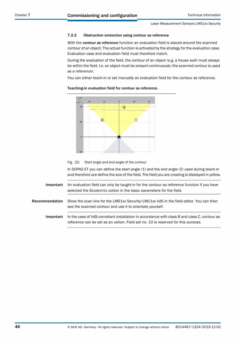
Teaching-in evaluation field for contour as reference.
Fig. 22: Start angle and end angle of the contour
In SOPAS ET you can define the start angle (1) and the end angle (2) used during teach-in and therefore pre-define the size of the field. The field you are creating is displayed in yellow.
Important An evaluation field can only be taught-in for the contour as reference function if you have
selected the SEGMENTED option in the basic parameters for the field.
Recommendation Show the scan line for the LMS1xx Security/LMC1xx VdS in the field editor. You can then see the scanned contour and use it to orientate yourself.
Important In the case of VdS-compliant installation in accordance with class B and class C, contour as reference can be set as an option. Field set no. 10 is reserved for this purpose.
46 © SICK AG · Germany · All rights reserved · Subject to change without notice 8014487/13Z4/2019-12-02

Commissioning and configurationTechnical information
Laser Measurement Sensors LMS1xx Security
Chapter 7
For the contour you must define the positive (2) and the negative (3) distance in relation to the scanned contour (1). The distance should be at least 100 mm (3.94 in), otherwise the contour will be continuously infringed.
Fig. 23: Positive and negative distance to the contour
How to teach-in an evaluation field for the contour as reference function:
1. In the selection field on the top right in the field editor choose the TEACH-IN CONTOUR option.The TEACH-IN CONTOUR dialog box is opened.
2. Enter the values for FIRST ANGLE and LAST ANGLE as well as for the POSITIVE DISTANCE and the NEGATIVE DISTANCE.
3. Click the START button.The contour will be scanned.
4. Then, click the STOP button.The evaluation field with its end points and start points is placed around the contour and displayed.
Manually editing evaluation field for contour as reference
Recommendation Show the scan line for the LMS1xx Security/LMC1xx VdS in the field editor. You can then see the scanned contour and use it to orientate yourself.
Fig. 24: Evaluation field for contour as reference
8014487/13Z4/2019-12-02 © SICK AG · Germany · All rights reserved · Subject to change without notice 47

Commissioning and configuration Technical information
Laser Measurement Sensors LMS1xx Security
Chapter 7
With end points (1) and start points (2) you can define the size of the field that you want to place around the contour of the object (3).
How to manually edit an evaluation field for the contour as reference:
1. In the selection field on the top right in the field editor choose the MANUAL option.
2. Set the end points of the evaluation field.
3. Set the start points of the evaluation field.
4. Ensure the positive and negative distance to the scanned contour for the field is sufficient (> 100 mm (3.94 in)).
7.3 Validity check
The validity check is mandatory on the LMC12x/LMC13x and cannot be deactivated as it can on the security devices.
Tampering within the monitored field areas is prevented with this function.
It is used for final testing and prevents incorrect set-up of the monitoring fields. In a VdS-compliant installation the TEACH-IN VALIDITY AREA function must be run once at the end.
Fig. 25: Validity check on the LMC12x/LMC13x
The following status can be indicated:
OpenValidity check has not yet been undertaken (new fields have been defined, existing fields have been modified or deleted).
InvalidTaught-in contour is invalid (e.g. half of the beams for a field are invalid).
ValidContour has been successfully taught-in.Validity signifies that every laser beam in every angular segment is checked for valid and stable measured values. This test is however only performed for the angular areas in which monitoring fields have been defined. In this way it is ensured that sufficient measured values are available that the LMS can evaluate.
During the validity check all set-up fields are checked for validity.
If all fields are valid, the fault output is cleared and as a result the fault signal removed. If the monitoring fields configured are not found to be valid, the fault output remains activated and generates a fault message.
In the SOPAS ET user interface the outputs are changed from orange to gray.
Important If new fields are defined, or existing fields are modified or deleted, the validity check must be performed again. If this action is not undertaken by the installer, the fault output remains active.
48 © SICK AG · Germany · All rights reserved · Subject to change without notice 8014487/13Z4/2019-12-02

Commissioning and configurationTechnical information
Laser Measurement Sensors LMS1xx Security
Chapter 7
7.4 EasyTeach
With this function an automatic teaching can be started by switching the digital switching input 4. There are three modes available for Easy Teach: INACTIVE, LITE and PRO.
The LMS1xx can be used with up to 10 fields (LMS14x Core: 4 fieldsr). The Lite-Mode can be used, if only one autoteach-in field is required. The Pro-Mode offers the possibility to teach in up to five different fields on the basis of preconfigured master-fields.
This function can be deactivated. The factory setting includes the activated Lite-Mode. This offers the possibility of teaching in a field (Field 1) without using a PC.
For both modes a minimum duration time can be set. It defines the minimum time, how long the teaching process will last once the trigger (Input 4) is activated. This parameter will allow the scanner to do an EasyTeach without the need to hold the trigger input, only a short single pulse is required.
The modes may be chosen by users of level “Integrator” and above.
7.4.1 Mode of Operation
In general the teach-in starts as soon as the digital switching input 4 is switched to “Active High” (factory default). While the input is set, the teaching is in process. In order to influence the field, it can be even limited manually by walking as person around the requested field. (To do so, please wear at least light cloths). The sensor stores the nearest value measured during the teaching process on each angle. When switching input 4 becomes inactive, the values are stored in the sensor and the field is activated.
7.4.2 Mode "Lite"
In this mode, the sensor starts the teach-in of the angle range with the activation of digital switching input 4. When the input gets inactive, the process is finished and all the values are stored permanently.
The “minimum duration time” defines the minimum time span for the teach-in process. This means that the process is expanded to this time, if the digital switching input is activated for a shorter period of time.
There are two field modes available, “Field Contour” or “Reference Contour”.
8014487/13Z4/2019-12-02 © SICK AG · Germany · All rights reserved · Subject to change without notice 49

Commissioning and configuration Technical information
Laser Measurement Sensors LMS1xx Security
Chapter 7
Standard settings for EasyTeach Field
In order to change these values, the user level needs to be at least „Integrator“.
To enable a simple plug&play, an evaluation case is generated automatically.
The following parameters can be changed:
7.4.3 Mode "Pro"
In the Pro-Mode, up to five EasyTeach fields can be defined for automated field generation over the digital switching input. These fields require defined background fields as patterns or region of interest. Background/pattern fields also work as limits for the EasyTeach field. Each EasyTeach field can have its own pattern field.
The teach-in of several fields at one time is possible. The field type of the pattern fields is not relevant.
Are scan points during teach-in within the borders of the pattern field, the borders will be adjusted. The pattern fields define the maximum extension of the final fields. The pattern fields can be chosen from the field numbers 1 to 5. The resulting fields are field numbers 6 to 10. The digital switching input and the field numbers cannot be changed.
The minimum distance to contour can be adjusted for each field separately as well as the minimum duration time for the teach-in.
When no evaluation case for the final fields is available, the sensor selects the standard settings as described in Section 7.4.2 “Mode " Lite"” on page 49.
Feature Value
Field number 1
Field name EasyTeach Field
Start angle –45°
Stop angle 225°
Min. distance to contour 250 mm
Min. distance beyond contour 250 mm
Input 4
Mode Konturfeld
Minimum duration 250 ms
Tab. 23: Standard settings for EasyTeach Field
50 © SICK AG · Germany · All rights reserved · Subject to change without notice 8014487/13Z4/2019-12-02

Commissioning and configurationTechnical information
Laser Measurement Sensors LMS1xx Security
Chapter 7
Procedure
As a first step the customer must create one or more pattern fields defining the maximum borders of the fields, which should be generated in SOPAS Field Editor.
Each EasyTeach field to be created must be defined or configured. Each EasyTeach field has its own parameters. The pattern fields which will be used for the EasyTeach Pro should be filled in with the particular field number. Name, mode and the minimum distance to contour can be adjusted, if required. Finally the teach-in with the digital switching input 4 can be initiated.
Behavour of LEDs (only with activated front panel)
During teach-in, Q2 is on permanently. When the teach-in is finished, Q2 starts blinking for around 10 seconds to visualize the end of the teach-in. In this time the field is set up and saved permanently.
During this time, the measurement is stopped, the LED "OK" goes off and the LED "STOP" is on. When the save process is finished, the measurement is started again, the LED "STOP" goes off and the LED "OK" is on.
Outputs
If the evaluation cases are set up automatically, output 1 is used.
8014487/13Z4/2019-12-02 © SICK AG · Germany · All rights reserved · Subject to change without notice 51

Commissioning and configuration Technical information
Laser Measurement Sensors LMS1xx Security
Chapter 7
Special Cases
Shading of the pattern field
If there is an object ahead of the pattern field and shades it completely or partially, this is treated depending on the field type.
Reference Contour Field
In the shaded areas the contours of the pattern field remain for the resulting field (Fig. 26).
As the obstruction protection is always active with this field type, a field that is infringed in
teach-in state is set up.
Field Contour
In this case the field start and the field end are on one line in the shaded area which is oriented at the start of the pattern field (Fig. 27 on page 53 und Fig. 28 on page 53).
When in this case obstruction protection is inactive (standard setting), there will be no report of this field infringement.
Fig. 26: Shaded reference contour field (yellow) at teach-in with pattern field (grey and yellow)
52 © SICK AG · Germany · All rights reserved · Subject to change without notice 8014487/13Z4/2019-12-02

Commissioning and configurationTechnical information
Laser Measurement Sensors LMS1xx Security
Chapter 7
Fig. 27: Teach-in of field contour with shading
Fig. 28: Teach-in of field contour field (green) with shading with pattern field (grey)
8014487/13Z4/2019-12-02 © SICK AG · Germany · All rights reserved · Subject to change without notice 53

Commissioning and configuration Technical information
Laser Measurement Sensors LMS1xx Security
Chapter 7
No object in the measuring range
If there is no object within the measuring range, the distances are set to the maximum measuring distance deducting the minimum distance in the field contour mode.
In the reference contour mode the field gets invalid.
Minimum distance to contour leads to exceedance of the pattern field
If a point lies outside the borders of the pattern field because of the minimum distance, this is treated like described in Section “Shading of the pattern field” on page 52. If a point is moved inside the pattern field because of the minimum distance, it merges in the field.
Using an existing field for EasyTeach
When an existing field is used for teach-in and the teach-in process is started, the existing field is replaced by the generated.
54 © SICK AG · Germany · All rights reserved · Subject to change without notice 8014487/13Z4/2019-12-02

Commissioning and configurationTechnical information
Laser Measurement Sensors LMS1xx Security
Chapter 7
7.5 Automatic Field Adaption
This feature has been designed for some particular situations. If the sensor is setup to perform a façade monitoring, as an example, there will be a field looking down to the ground level. In the case of snow falling, the level of the snow on the ground will slowly raise to a point where it could infringe the monitoring field.
With the Automatic Field Adaption feature the field will adapt automatically to the shape of the slowly growing snow, as described in the example.
An evaluation case can be configured so that its linked field will be automatically adapted under certain circumstances, for example growing grass, snow piling up and others. In the parameterization assistant of an evaluation case the following settings can be set:
Enable/disable automatic field adaption
Set output to signal field adaption
Set max. possible velocity which determines, if field adaption is valid/possible
With this function activated the sensor will evaluate the edge of the field for any slow intrusion into the setup field.
The speed of the intrusion is determined by the velocity setting.
8014487/13Z4/2019-12-02 © SICK AG · Germany · All rights reserved · Subject to change without notice 55

Commissioning and configuration Technical information
Laser Measurement Sensors LMS1xx Security
Chapter 7
When snow or grass is starting to “touch” the field, the Automatic Field Adaption will trigger. When this triggering is happening the sensor can signalise this triggering via the selected output.
7.6 Contamination measurement
The LMS1xx Security/LMC1xx VdS has an optics cover for protection. This optics cover can become contaminated. For this reason the contamination is measured continuously while the device is in operation. From a certain contamination level, initially a contamination warning is output; if the contamination becomes worse, a contamination error is output and the LMS1xx Security/LMC1xx VdS disables the measurement mode.
Depending on the application in which the LMS1xx Security/LMC1xx VdS is used, you can choose between various strategies for the contamination measurement:
PROJECT TREE, LMS/LMC, PARAMETER, CONTAMINATION MEASUREMENT
INACTIVE: No contamination measurement
HIGHLY AVAILABLE: Contamination warning and contamination error are only output on even contamination of the optics cover.
AVAILABLE: Contamination warning and contamination error are only output on partial contamination of the optics cover.
SENSITIVE: Contamination warning and contamination error are output even with isolated contamination.
You will find further information on the various strategies for contamination measurement in the „LMS1xx Laser Measurment Sensor“ operating instructions (part no. 8012471, English version).
7.7 Additional settings for the LMS12x/LMS13x/LMS14x Security
In the Expert mode special settings for reducing the false alarm rate can be set. Here among others a fog filter, hardware blanking window, echo filter, particle filter or mean value filter can be activated, and also different object sizes can be set specifically for blanking.
As on the security variants it is possible to make changes in the Expert mode, it is imperative the settings on these devices are checked in relation to the specific application prior to commissioning.
56 © SICK AG · Germany · All rights reserved · Subject to change without notice 8014487/13Z4/2019-12-02

MaintenanceTechnical information
Laser Measurement Sensors LMS1xx Security
Chapter 8
8 Maintenance
Claims under the warranty rendered void!!
The housing screws of the detection sensor are sealed. Claims under the warranty against SICK AG will be rendered void if the seals are damaged or the device opened. The housing is only allowed to be opened by authorized service personnel.
8.1 Maintenance during operation
8.1.1 Cleaning the optics cover
The detection sensor is largely maintenance-free. The optics cover on the detection sensor should however be cleaned regularly and if it is contaminated (see section 7.4 “EasyTeach” on page 49). The frequency of cleaning is defined by the local ambient conditions.
Do not use aggressive detergents.
Do not use abrasive cleaning agents.
Important Static charges cause dust particles to be attracted to the optics cover.
You can diminish this effect by using the anti-static plastic cleaner (SICK part no. 5600006) and the SICK lens cloth (part no. 4003353). See also Section 10.1.3 “Consumables” on page 78.
How to clean the optics cover:
1. Use a clean and soft brush to remove dust from the optics cover.
2. Wipe the view window of the optics cover with a clean and damp cloth.
8014487/13Z4/2019-12-02 © SICK AG · Germany · All rights reserved · Subject to change without notice 57

Maintenance Technical information
Laser Measurement Sensors LMS1xx Security
Chapter 8
8.2 Exchanging an LMS1xx Security/LMC1xx VdS
Incorrect or damaged LMS1xx Security/LMC1xx VdS have to removed and reclaped with either new or repaired LMS1xx Security/LMC1xx VdS of the same type.
As all external cable connections end in the system connector or in the round plug-in connectors, it is not necessary to re-install the device electrically on a device replacement. The replacement unit of the same type can then be simply connected.
Cloning (LMS12x Security only)
The sensor saves the parameter values permanently in its internal, non-volatile parameter memory. Additionally, it always saves a permanent copy of the parameter set in the parameter memory of the system plug. (This is initiated using SOPAS ET and the “Save permanent” function.)
If an LMS1xx Security/LMC1xx VdS is replaced, after start-up the replacement device checks whether there is a plausible parameter set in the system plug. If so, the sensor loads this parameter set into its working memory.
Since the existing system plug is reused, a replacement device of the same type can automatically inherit the most recently used parameter values in the system plug (cloning).
Cloning involves the replacement device accepting all the adjustable parameters, including the IP address. Accordingly, the process overwrites all the existing parameter values stored in the device.
The exceptions in this case are the following parameters, which are always device-specific: serial number, MAC address, operating hours counter, and error memory.
If the LMS1xx Security/LMC1xx VdS is to be replaced, proceed as follows:
8.2.1 LMS1xx Security
LMS12x Security:
1. Switch off the voltage supply for the sensor.
2. Remove the sensor from the holder. If necessary, mark the sensor's situation and alignment on the holder or environment.
3. Loosen the system connector on the bottom of the sensor (4 screws) and remove it togehter with all cables.
4. Also remove the system connector on the replacement device.
5. Plug and fix the former system connector on the bottom of the replacement device.
6. Mount the replacement device to the holder (see Chapter 5 “Mounting” on page 29) and check the correct orientation of the device.
If the previous system plug was not reused:
7. Configure the replacement device (see Chapter 7 “Commissioning and configuration” on page 41).
LMS13x/LMS14x Security:
1. Switch off the voltage supply for the sensor.
2. Loosen and remove all connection cables from the system connector on the bottom of the sensor.
3. Remove the sensor from the holder. If necessary, mark the sensor's situation and alignment on the holder or environment.
4. Mount the replacement device to the holder (see Chapter 5 “Mounting” on page 29)
58 © SICK AG · Germany · All rights reserved · Subject to change without notice 8014487/13Z4/2019-12-02

MaintenanceTechnical information
Laser Measurement Sensors LMS1xx Security
Chapter 8
and check the correct orientation of the device.
5. Re-connect all connection cables to the system connector of the replacement device and and fix them.
6. Configure the replacement device (see Chapter 7 “Commissioning and configuration” on page 41).
8.2.2 LMC1xx VdS
LMC12x VdS:
1. Switch off the voltage supply for the sensor.
2. Remove the sensor from the VdS mounting kit 1 or 2:Do do so, remove the 4 sealing strips on the sides of the roughcast bush steel sheet.Loosen the 4 screws of the roughcast bush steel sheet and remove the steel sheet upwards.
3. Loosen the 4 screws of the VdS device clamp on the sensor and carefully excerpt the sensor a small distance with all cables.
8014487/13Z4/2019-12-02 © SICK AG · Germany · All rights reserved · Subject to change without notice 59

Maintenance Technical information
Laser Measurement Sensors LMS1xx Security
Chapter 8
4. Loosen the system connector on the bottom of the sensor (4 screws) and remove it together with all cables.
5. Also remove the system connector on the replacement device.
6. Plug and fix the former system connector on the bottom of the replacement device.
7. Insert the replacement device into VdS device clamp and fix it (see Chapter 5 “Mounting” on page 29).
8. Fix one of the 5 sealing strips, provided with the replacement device, to the AUX connection (on front of device), according to Chapter 5.1 “Sealing the LMC12x/LMC13x” on page 29.
9. Impose the roughcast bush steel sheet of the VdS mounting kit on the sensor and fix it to the basic housing of the sensor.
10. Fix the remaining 4 sealing strips to the am roughcast bush steel sheet covering the screws.
11. Configure the replacement device (see Chapter 7 “Commissioning and configuration” on page 41).
LMC13x VdS:
1. Switch off the voltage supply for the sensor.
2. Remove the sensor from the VdS mounting kit 1 or 2:Do do so, remove the 4 sealing strips on the sides of the roughcast bush steel sheet.Loosen the 4 screws of the roughcast bush steel sheet and remove the steel sheet upwards.
3. Loosen and remove all connection cables from the system connector on the bottom of the sensor.
4. Loosen the 4 screws of the VdS device clamp on the sensor and carefully remove the sensor.
5. Insert the replacement device into VdS device clamp and fix it (see Chapter 5 “Mounting” on page 29).
6. Re-connect all connection cables to the system connector of the replacement device and and fix them.
7. Fix one of the 5 sealing strips, provided with the replacement device, to the AUX connection (on front of device), according to Chapter 5.1 “Sealing the LMC12x/LMC13x” on page 29.
8. Impose the roughcast bush steel sheet of the VdS mounting kit on the sensor and fix it to the basic housing of the sensor.
9. Fix the remaining 4 sealing strips to the am roughcast bush steel sheet covering the screws.
10. Configure the replacement device (see Chapter 7 “Commissioning and configuration” on page 41).
60 © SICK AG · Germany · All rights reserved · Subject to change without notice 8014487/13Z4/2019-12-02

MaintenanceTechnical information
Laser Measurement Sensors LMS1xx Security
Chapter 8
8.3 Troubleshooting
8.3.1 Error displays of the LEDs
Important On the LMS1xx Security/LMC1xx VdS the status indicators are switched off so that as far as possible it cannot be seen that the device is part of an object protection system. In the Function test mode and in the unarmed state these are switched on.
8014487/13Z4/2019-12-02 © SICK AG · Germany · All rights reserved · Subject to change without notice 61

Maintenance Technical information
Laser Measurement Sensors LMS1xx Security
Chapter 8
62 © SICK AG · Germany · All rights reserved · Subject to change without notice 8014487/13Z4/2019-12-02
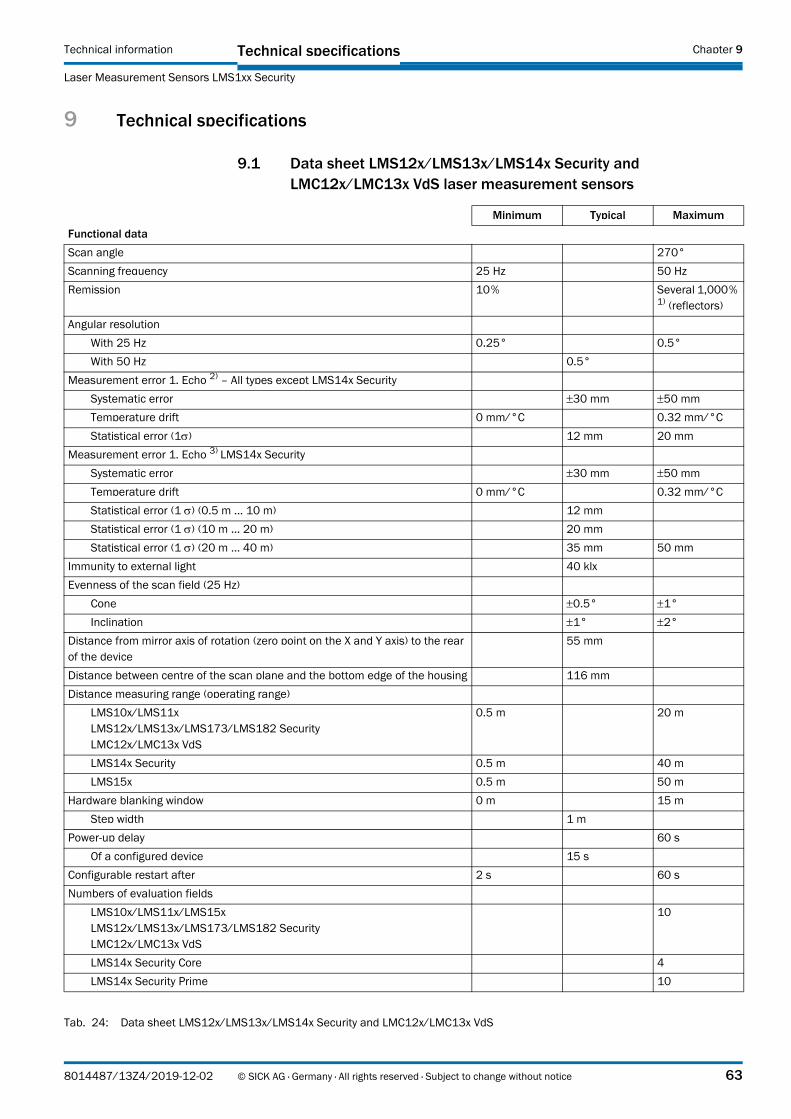
Technical specificationsTechnical information
Laser Measurement Sensors LMS1xx Security
Chapter 9
9 Technical specifications
9.1 Data sheet LMS12x/LMS13x/LMS14x Security and LMC12x/LMC13x VdS laser measurement sensors
Minimum Typical Maximum
Functional data
Scan angle 270°
Scanning frequency 25 Hz 50 Hz
Remission 10 % Several 1,000 % 1) (reflectors)
Angular resolution
With 25 Hz 0.25° 0.5°
With 50 Hz 0.5°
Measurement error 1. Echo 2) – All types except LMS14x Security
Systematic error 30 mm 50 mm
Temperature drift 0 mm/°C 0.32 mm/°C
Statistical error (1) 12 mm 20 mm
Measurement error 1. Echo 3) LMS14x Security
Systematic error 30 mm 50 mm
Temperature drift 0 mm/°C 0.32 mm/°C
Statistical error (1 ) (0.5 m ... 10 m) 12 mm
Statistical error (1 ) (10 m ... 20 m) 20 mm
Statistical error (1 ) (20 m ... 40 m) 35 mm 50 mm
Immunity to external light 40 klx
Evenness of the scan field (25 Hz)
Cone 0.5° 1°
Inclination 1° 2°
Distance from mirror axis of rotation (zero point on the X and Y axis) to the rear of the device
55 mm
Distance between centre of the scan plane and the bottom edge of the housing 116 mm
Distance measuring range (operating range)
LMS10x/LMS11xLMS12x/LMS13x/LMS173/LMS182 SecurityLMC12x/LMC13x VdS
0.5 m 20 m
LMS14x Security 0.5 m 40 m
LMS15x 0.5 m 50 m
Hardware blanking window 0 m 15 m
Step width 1 m
Power-up delay 60 s
Of a configured device 15 s
Configurable restart after 2 s 60 s
Numbers of evaluation fields
LMS10x/LMS11x/LMS15xLMS12x/LMS13x/LMS173/LMS182 SecurityLMC12x/LMC13x VdS
10
LMS14x Security Core 4
LMS14x Security Prime 10
Tab. 24: Data sheet LMS12x/LMS13x/LMS14x Security and LMC12x/LMC13x VdS
8014487/13Z4/2019-12-02 © SICK AG · Germany · All rights reserved · Subject to change without notice 63

Technical specifications Technical information
Laser Measurement Sensors LMS1xx Security
Chapter 9
General data
Laser class Laser class 1 according IEC 60 825-1:2014(wavelength 905 nm, max. pulse power 54 W, max. pulse width 5 ns)-
Enclosure rating As per EN 60 529 (1991-10); A1 (2002-02)
LMS12x SecurityLMC12x VdS
IP 65
LMS13x/LMS14x SecurityLMC13x VdS
IP 67 4)
Protection class III as per EN 50 178 (1997-10)
EMC test As per EN 61 000-6-2 (2005-08), EN 61 000-6-3 (2007-03)
Electrical safety As per EN 50 178 (1997-10)
Operating ambient temperature range
LMS12x SecurityLMC12x VdS
0 °C +50 °C
LMS13x SecurityLMC13x VdS
–30 °C +50 °C
LMC12x VdS with mounting kit 1 –30 °C +45 °C
LMC12x VdS with mounting kit 2 –30 °C +50 °C
LMS14x Security –40 °C +60 °C
Storage ambient temperature range
Alle Typen außer LMS14x Security –30 °C +70 °C, max. 24 h
LMS14x Security –40 °C +70 °C, max. 24 h
Humidity (taking into account the operating temperature range) As per DIN EN 60 068-2-61, Method 1
Max. 95%rF, non-condensing
Vibration resistance As per EN 60 068-2-6 (1995-04)
Frequency range 10 Hz 150 Hz
Amplitude 5 g RMS
Shock resistance As per EN 60 068-2-27 (1993-03), EN 60 068-2-29 (1993-04)
Single shock 15 g, 11 ms
Continuous shock 10 g, 16 ms
Installation height < 5,000 m above sea level
Sender Pulsed laser diode
Wave length 895 nm 905 nm 915 nm
Divergence of the collimated beam (solid angle) 15 mrad
Light spot size at the optics cover 8 mm
Light spot size at 18 m scanning range 300 mm
Housing
Material GD-ALSI12 3.2582.05
Color LMS1x1/LMC1x1 RAL 7032 (pebble gray)
Color LMS1x2/LMC1x2 RAL 9005 (jet black)
Color LMS1x3/LMC1x3 RAL 9003 (signal white)
Color LMC124 RAL 9005 (jet black)VdS-mounting kit: uncoated aluminium
Minimum Typical Maximum
Tab. 24: Data sheet LMS12x/LMS13x/LMS14x Security and LMC12x/LMC13x VdS (cont.)
64 © SICK AG · Germany · All rights reserved · Subject to change without notice 8014487/13Z4/2019-12-02

Technical specificationsTechnical information
Laser Measurement Sensors LMS1xx Security
Chapter 9
Alloy Excellent weather resistance as per DIN EN 106:1988, plate 3
Minimum Typical Maximum
Tab. 24: Data sheet LMS12x/LMS13x/LMS14x Security and LMC12x/LMC13x VdS (cont.)
8014487/13Z4/2019-12-02 © SICK AG · Germany · All rights reserved · Subject to change without notice 65

Technical specifications Technical information
Laser Measurement Sensors LMS1xx Security
Chapter 9
Optics cover
Material Polycarbonate
Surface finish Outside with scratch-resistant coating
System connector (LMS12x Security/LMC12x VdS)
Material GD-ALSI12 3.2582.05
Color RAL 9005 (jet black)
Cable entries (LMS13x Security/LMC13x VdS)
Material Stainless steel/plastic
Dimensions 5)
LMS12x SecurityLMC12x VdS
152 mm
LMS13x/LMS14x SecurityLMC13x VdS
162 mm
Width 102 mm
Depth 106 mm
Total weight (without connecting cables) 1.1 kg
Electrical data (Typical values: Apply to DC 24 V supply voltage unless otherwise stated)
Supply voltage sensorSELV or PELV as per IEC 60 364-4-41 (2005-12)
LMS12x/LMS13x/LMS14x SecurityLMC12x/LMC13x VdS
9 V 6) 24 V 30 V
Permissible residual ripple ±5 %
Supply voltage for the heatingSELV or PELV as per IEC 60 364-4-41 (2005-12)
LMS13x SecurityLMC13x VdS
19.2 V 24 V 28.8 V
LMS14x Security 21.6 V 24 V 28.8 V
All types
Switch on current 2 A
Operating current Sensor 0.33 A 0.4 A at DC 24 V1.0 A at DC 9 V
Power consumption Sensor 8 W 10 W
LMS13x/LMS 14x Security und LMC13x VdS
Power consumption Heating 35 W 45 W
Operating current (Sensor + Heating) with max. heating performance 1.8 A 2.6 A
Power consumption (Sensor + Heating) with max. heating performance 43 W 55 W
Minimum Typical Maximum
Tab. 24: Data sheet LMS12x/LMS13x/LMS14x Security and LMC12x/LMC13x VdS (cont.)
66 © SICK AG · Germany · All rights reserved · Subject to change without notice 8014487/13Z4/2019-12-02
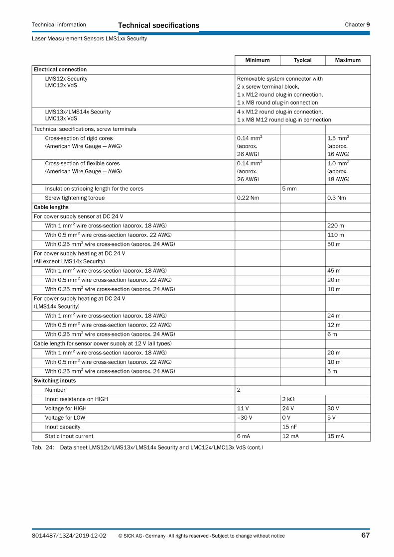
Technical specificationsTechnical information
Laser Measurement Sensors LMS1xx Security
Chapter 9
Electrical connection
LMS12x SecurityLMC12x VdS
Removable system connector with 2 x screw terminal block,1 x M12 round plug-in connection, 1 x M8 round plug-in connection
LMS13x/LMS14x SecurityLMC13x VdS
4 x M12 round plug-in connection,1 x M8 M12 round plug-in connection
Technical specifications, screw terminals
Cross-section of rigid cores(American Wire Gauge — AWG)
0.14 mm²(approx. 26 AWG)
1.5 mm²(approx. 16 AWG)
Cross-section of flexible cores(American Wire Gauge — AWG)
0.14 mm² (approx. 26 AWG)
1.0 mm² (approx. 18 AWG)
Insulation stripping length for the cores 5 mm
Screw tightening torque 0.22 Nm 0.3 Nm
Cable lengths
For power supply sensor at DC 24 V
With 1 mm² wire cross-section (approx. 18 AWG) 220 m
With 0.5 mm² wire cross-section (approx. 22 AWG) 110 m
With 0.25 mm² wire cross-section (approx. 24 AWG) 50 m
For power supply heating at DC 24 V (All except LMS14x Security)
With 1 mm² wire cross-section (approx. 18 AWG) 45 m
With 0.5 mm² wire cross-section (approx. 22 AWG) 20 m
With 0.25 mm² wire cross-section (approx. 24 AWG) 10 m
For power supply heating at DC 24 V (LMS14x Security)
With 1 mm² wire cross-section (approx. 18 AWG) 24 m
With 0.5 mm² wire cross-section (approx. 22 AWG) 12 m
With 0.25 mm² wire cross-section (approx. 24 AWG) 6 m
Cable length for sensor power supply at 12 V (all types)
With 1 mm² wire cross-section (approx. 18 AWG) 20 m
With 0.5 mm² wire cross-section (approx. 22 AWG) 10 m
With 0.25 mm² wire cross-section (approx. 24 AWG) 5 m
Switching inputs
Number 2
Input resistance on HIGH 2 k
Voltage for HIGH 11 V 24 V 30 V
Voltage for LOW –30 V 0 V 5 V
Input capacity 15 nF
Static input current 6 mA 12 mA 15 mA
Minimum Typical Maximum
Tab. 24: Data sheet LMS12x/LMS13x/LMS14x Security and LMC12x/LMC13x VdS (cont.)
8014487/13Z4/2019-12-02 © SICK AG · Germany · All rights reserved · Subject to change without notice 67

Technical specifications Technical information
Laser Measurement Sensors LMS1xx Security
Chapter 9
Relay switching outputs (semiconductor relay/MOSFET) LMS13x/LMS14x Security /LMC13x VdS, from 2012 also LMS12x Security/LMC12x VdS
Number 2
Switching voltage DC/AC 40 V
Switching current 0.5 A
Contact resistance 0.34 0.7 V
Output capacitance 220 pF
Input/output dielectric strength 1500 VAC
Power-up delay 1.3 ms 0.1 ms
Switch off time 0.1 ms 0.5 ms
Relay switching outputs LMS12x Security/LMC12x VdSup to 2012
Number 2
Switching capacity DC 30 W/AC 37.5 VA
Switching voltage DC 110 V/AC 125 V
Switching current 0.5 A at 30 V
Contact resistance 0.34 0.7
Switching cycles 105
Power-up delay 2 ms 4 ms
Switch off time 2 ms 4 ms
Serial auxiliary interface
Communication protocol RS-232 (proprietary)
Transmission speed 9.6 kBd 57.6 kBd 115.2 kBd
Serial host interface
Communication protocol RS-232 (proprietary)
Transmission speed (selectable) 9.6 kBd 57.6 kBd 115.2 kBd
Cable length at 38,4 kBd and wire cross-section 0.25 mm² (approx. 24 AWG) 15 m (49.21 ft)
Galvanic de-coupling Yes
Wire cross-section of the connecting cable 0.25 mm² (approx. 24 AWG)
Ethernet 10/100 Mbit/s
CAN 20 kBit/s, 500 kBit/s, 1 MBit/s
1) Corresponds to Diamond Grade 3000X™ (approx. 1,250 cd/lx × m²).2) After the first echo, you must wait a certain period of time before you can measure with full accuracy again. This depends on the target that reflected
the first echo.3) After the first echo, you must wait a certain period of time before you can measure with full accuracy again. This depends on the target that reflected
the first echo.4) Under the following conditions: the cables plugged into the M12 round plug-in connections must be screwed tight. Any electrical connections that
are not being used must be fitted with protective caps or plugs that are screwed tight (as in the delivery condition). The M8 connection on the front is screwed tight
5) Without fixing screws and projection of cable glands with system connector mounted.6) If the switching inputs are used, the mimimum switching voltage is at least DC 11 V
Minimum Typical Maximum
Tab. 24: Data sheet LMS12x/LMS13x/LMS14x Security and LMC12x/LMC13x VdS (cont.)
68 © SICK AG · Germany · All rights reserved · Subject to change without notice 8014487/13Z4/2019-12-02
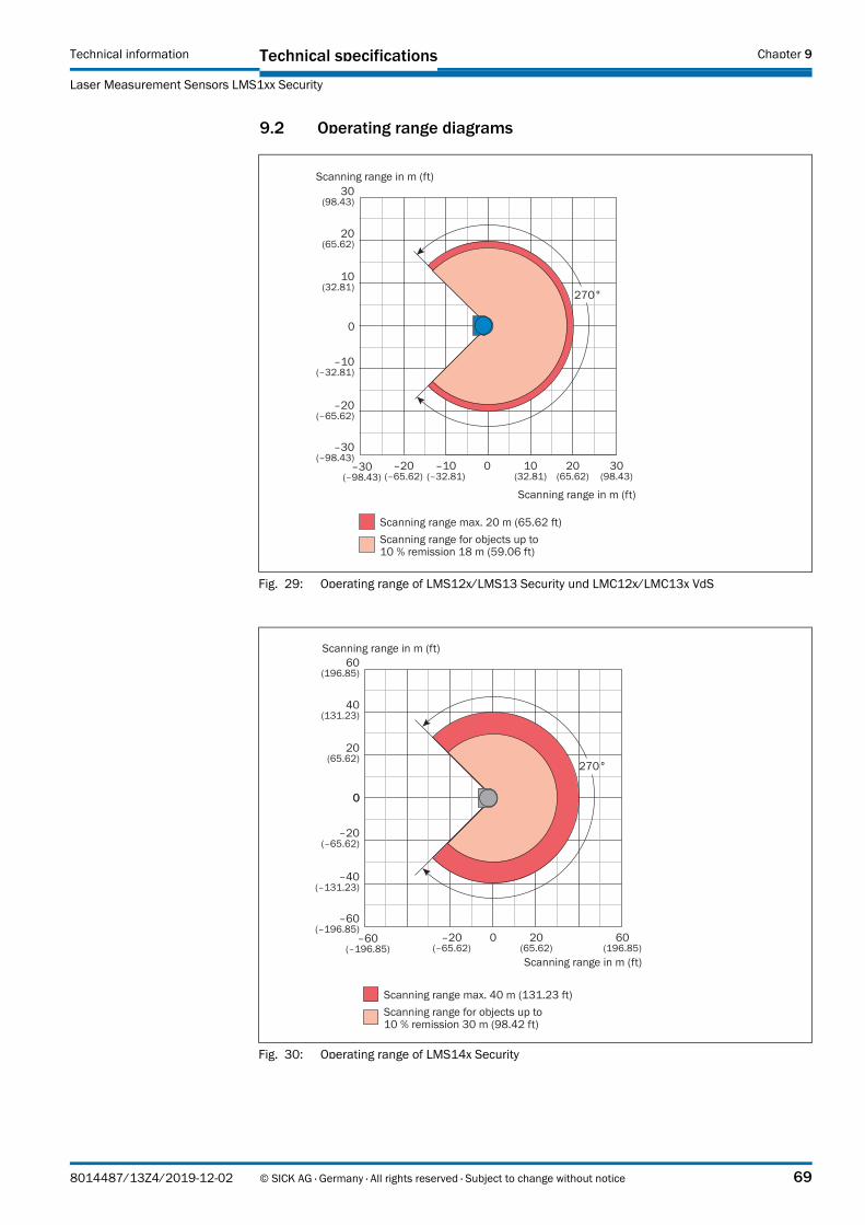
Technical specificationsTechnical information
Laser Measurement Sensors LMS1xx Security
Chapter 9
9.2 Operating range diagrams
Fig. 29: Operating range of LMS12x/LMS13 Security und LMC12x/LMC13x VdS
0
270°
Scanning range in m (ft)
–20(–65.62)
20(65.62)
–30(–98.43)
30(98.43)
–10(–32.81)
10(32.81)
Scanning range in m (ft)
–10(–32.81)
–20(–65.62)
10(32.81)
20(65.62)
30(98.43)
–30(–98.43)
0
Scanning range max. 20 m (65.62 ft)Scanning range for objects up to 10 % remission 18 m (59.06 ft)
Fig. 30: Operating range of LMS14x Security
0
–40(–131.23)
40(131.23)
–60(–196.85)
60(196.85)
–20(–65.62)
20(65.62)
270°
Scanning range in m (ft)
Scanning range in m (ft)
Scanning range max. 40 m (131.23 ft)Scanning range for objects up to 10 % remission 30 m (98.42 ft)
–20(–65.62)
20(65.62)
60(196.85)
–60(–196.85)
0
0
8014487/13Z4/2019-12-02 © SICK AG · Germany · All rights reserved · Subject to change without notice 69

Technical specifications Technical information
Laser Measurement Sensors LMS1xx Security
Chapter 9
9.3 Dimensional drawings
9.3.1 Dimensional drawing LMS12x Security and LMC12x VdS
Fig. 31: Dimensional drawing LMS12x Security and LMC12x VdS
Min. 15
116
23.8
Max
. 20
0
27
0°
10
58
19
10
.54
9
79.3
M5
× 7
.5
739
4
152115.7
79.3
All dimensions in mm
70 © SICK AG · Germany · All rights reserved · Subject to change without notice 8014487/13Z4/2019-12-02

Technical specificationsTechnical information
Laser Measurement Sensors LMS1xx Security
Chapter 9
9.3.2 Dimensional drawing LMS13x/LMS14x Security and LMC13x VdS
Fig. 32: Dimensional drawing LMS13x/LMS14x Security and LMC13x VdS
Max
. 20
0
Min. 15
All dimensions in mm
116
23.8
27
0°
10
5
10
.54
9
79.3 10
M5 ×
7.5
73
94
152115.7
79.3
8014487/13Z4/2019-12-02 © SICK AG · Germany · All rights reserved · Subject to change without notice 71

Technical specifications Technical information
Laser Measurement Sensors LMS1xx Security
Chapter 9
9.3.3 Dimensional drawings LMS1xx Security/LMC1xx VdS with mounting kits
Fig. 33: Dimensional drawing LMC12x VdS with VdS mounting kit 1
adju
stab
le
adju
stab
le
All dimensions in mm
72 © SICK AG · Germany · All rights reserved · Subject to change without notice 8014487/13Z4/2019-12-02

Technical specificationsTechnical information
Laser Measurement Sensors LMS1xx Security
Chapter 9
Fig. 34: Dimensional drawing LMC12x VdS with VdS mounting kit 2
adju
stab
le
adju
stab
le
All dimensions in mm
8014487/13Z4/2019-12-02 © SICK AG · Germany · All rights reserved · Subject to change without notice 73

Technical specifications Technical information
Laser Measurement Sensors LMS1xx Security
Chapter 9
Fig. 35: Dimensional drawing LMC13x VdS with VdS mounting kit 2
adju
stab
le
adju
stab
le
All dimensions in mm
74 © SICK AG · Germany · All rights reserved · Subject to change without notice 8014487/13Z4/2019-12-02
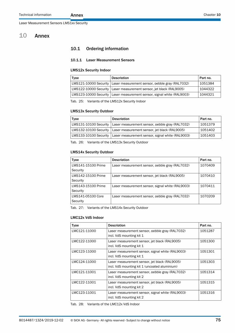
AnnexTechnical information
Laser Measurement Sensors LMS1xx Security
Chapter 10
10 Annex
10.1 Ordering information
10.1.1 Laser Measurement Sensors
LMS12x Security Indoor
LMS13x Security Outdoor
LMS14x Security Outdoor
LMC12x VdS Indoor
Type Description Part no.
LMS121-10000 Security Laser measurement sensor, pebble gray (RAL7032) 1051384
LMS122-10000 Security Laser measurement sensor, jet black (RAL9005) 1044322
LMS123-10000 Security Laser measurement sensor, signal white (RAL9003) 1044321
Tab. 25: Variants of the LMS12x Security Indoor
Type Description Part no.
LMS131-10100 Security Laser measurement sensor, pebble gray (RAL7032) 1051379
LMS132-10100 Security Laser measurement sensor, jet black (RAL9005) 1051402
LMS133-10100 Security Laser measurement sensor, signal white (RAL9003) 1051403
Tab. 26: Variants of the LMS13x Security Outdoor
Type Description Part no.
LMS141-15100 Prime Security
Laser measurement sensor, pebble gray (RAL7032) 1070409
LMS142-15100 Prime Security
Laser measurement sensor, jet black (RAL9005) 1070410
LMS143-15100 Prime Security
Laser measurement sensor, signal white (RAL9003) 1070411
LMS141-05100 Core Security
Laser measurement sensor, pebble gray (RAL7032) 1070209
Tab. 27: Variants of the LMS14x Security Outdoor
Type Description Part no.
LMC121-11000 Laser measurement sensor, pebble gray (RAL7032)incl. VdS mounting kit 1
1051287
LMC122-11000 Laser measurement sensor, jet black (RAL9005)incl. VdS mounting kit 1
1051300
LMC123-11000 Laser measurement sensor, signal white (RAL9003)incl. VdS mounting kit 1
1051301
LMC124-11000 Laser measurement sensor, jet black (RAL9005)incl. VdS mounting kit 1 (uncoated aluminium)
1051303
LMC121-11001 Laser measurement sensor, pebble gray (RAL7032)incl. VdS mounting kit 2
1051314
LMC122-11001 Laser measurement sensor, jet black (RAL9005)incl. VdS mounting kit 2
1051315
LMC123-11001 Laser measurement sensor, signal white (RAL9003)incl. VdS mounting kit 2
1051316
Tab. 28: Variants of the LMC12x VdS Indoor
8014487/13Z4/2019-12-02 © SICK AG · Germany · All rights reserved · Subject to change without notice 75

Annex Technical information
Laser Measurement Sensors LMS1xx Security
Chapter 10
LMC13x VdS Outdoor
10.1.2 Deliverable Accessoires
Mounting Kits for LMS1xx Security
Weather Protection Hoods for LMS1xx Security
Important The LMC1xx VdS cannot be fastened with a weather protection hood.
For dimensional drawings of the weather protection hoods, please see “LMS1xx Laser
Measurement Sensors“ operating instructions (part.no. 8012471, English verions).
Type Description Part no.
LMC131-11101 Laser measurement sensor, pebble gray (RAL7032)incl. VdS mounting kit 2
1051487
LMC132-11101 Laser measurement sensor, jet black (RAL9005)incl. VdS mounting kit 2
1051488
LMC133-11101 Laser measurement sensor, signal white (RAL9003)incl. VdS mounting kit 2
1051489
Tab. 29: Variants of the LMC13x VdS Outdoor
Description Part no.
Mounting kit 1a 1), black.Bracket for mounting to wall or machine from the back
2034324
Mounting kit 1b1), black. Bracket for mounting to wall or machine from the back, with cover protection
2034325
Mounting kit 2 1), black. Bracket, only in combination with bracket 1a or 1b, adjust-ment possible around transverse axis
2039302
Mounting kit 3 1), black. Retention plate, only in combination with bracket 2, adjust-ment possible around longitudinal axis
2039303
1) Including mounting material for laser mesasurement sensor
Tab. 30: Mounting kits for LMS1xx Security
Description Part no.
Weather protection hood, 1), viewing range 190° 2046459
Weather protection hood, 1), viewing range 270° 2046458
Standard mounting kit for weather protection hood 190°/270° 2046025
Rapid-release mounting kit for weather protection hood 190°/270° 2046989
1) Including mounting material for laser mesasurement sensor
Tab. 31: Weather protection hoods for LMS1xx Security
76 © SICK AG · Germany · All rights reserved · Subject to change without notice 8014487/13Z4/2019-12-02

AnnexTechnical information
Laser Measurement Sensors LMS1xx Security
Chapter 10
VdS Mounting Kits for LMC1xx VdS
Important It is not possible to subsequently upgrade an LMS1xx Security to an LMC1xx VdS using the VdS mounting kits.
Data cables (Ethernet, RS-232) for LMS1xx Security/LMC1xx VdS
Description Part no.
VdS mounting kit 1 1), pebble gray (RAL7032) 2056270
VdS mounting kit 1 1), jet black (RAL9005) 2056271
VdS mounting kit 1 1), signal white (RAL9003) 2052396
VdS mounting kit 1 1), uncoated aluminium 2056272
VdS mounting kit 2 1), pebble gray (RAL7032) 2056374
VdS mounting kit 2 1), jet black (RAL9005) 2056375
VdS mounting kit 2 1), signal white (RAL9003) 2056376
1) Including mounting material for laser mesasurement sensor
Tab. 32: VdS Mounting kits
Type Description Part no.
SSL-2J04-G10ME Ethernet cable, twisted pair, shielded, AWG 26, with 4-pin M12 male connector (D-coded), IP 65 and 8-pin RJ45-male connector, Length 5 m. For "Ethernet" connection
6034415
SSL-2J04-G10ME Ethernet cable, twisted pair, shielded, AWG 26, with 4-pin M12 male connector (D-coded), IP 65 and 8-pin RJ45-male connector, Length 10 m. For "Ethernet" connection
6030928
SSL-2J04-G20ME Ethernet cable, twisted pair, shielded, AWG 26, with 4-pin M12 male connector (D-coded), IP 65 and 8-pin RJ45-male connector, Length 20 m. For "Ethernet" connection
6036158
DSL-8D04G02M025KM1 Data cable cable (RS-232), shielded, with 4-pin M8 male connector and 9-pin Sub-D female connector, Length 2 m. For parameterization via "Aux" connection
6021195
DSL-8D04G10M025KM1 Data cable cable (RS-232), shielded, with 4-pin M8 male connector and 9-pin Sub-D female connector, Length 10 m. For parameterization via "Aux" connection
2027649
Tab. 33: Data cables for connecting the LMS1xx Security/LMC1xx VdS to the host or PC
8014487/13Z4/2019-12-02 © SICK AG · Germany · All rights reserved · Subject to change without notice 77

Annex Technical information
Laser Measurement Sensors LMS1xx Security
Chapter 10
Cable for LMS13x/LMS14x Security and LMC13x VdS
For pin and core color assignment of cables with open end, please see “LMS1xx Laser
Measurement Sensors“ operating instructions (part.no. 8012471, English verions).
Important For the VdS versions a cable without color coding can be supplied on request.
In case of VdS-compliant installation, the power supply must be designed correspondingly.
10.1.3 Consumables
10.2 EU declaration of conformity, VdS certificate, other certificates
The EU declaration of conformity and other certificates (e.g., VdS) can be downloaded from the Internet at:
http://www.sick.com/lms1xx
http://www.sick.com/lmc1xx
Description Part no.
Supply cable, 4-core, shielded, with 5-pin M12 female connector (A-coded) and flying leads (open end), Length 5 m. For "Power" connection
6036159
Supply cable, 4-core, shielded, with 5-pin M12 female connector (A-coded) and flying leads (open end), Length 10 m. For "Power" connection
6036160
Supply cable, 4-core, shielded, with 5-pin M12 female connector (A-coded) and flying leads (open end), Length 20 m. For "Power" connection
6036161
I/O cable, 8 core, shielded, AWG 24, with 8-pin M12 male connector (A-coded) and fly-ing leads (open end), Length 5 m. For "I/0" connection
6036155
I/O cable, 8 core, shielded, AWG 24, with 8-pin M12 male connector (A-coded) and fly-ing leads (open end), Length 10 m. For "I/0" connection
6036156
I/O cable, 8 core, shielded, AWG 24, with 8-pin M12 male connector (A-coded) and fly-ing leads (open end), Length 20 m. For "I/0" connection
6036157
Data cable (RS-232, CAN), 8 core, shielded, AWG 24, with 8-pin M12 female connector (A-coded) and flying leads (open end), Length 5 m. For "Data" connection
6036153
Data cable (RS-232, CAN), 8 core, shielded, AWG 24, with 8-pin M12 female connector (A-coded) and flying leads (open end), Length 10 m. For "Data" connection
6028420
Data cable (RS-232, CAN), 8 core, shielded, AWG 24, with 8-pin M12 female connector (A-coded) and flying leads (open end), Length 20 m. For "Data" connection
6036154
Tab. 34: Cables for LMS13x/LMS14x Security and LMC13x VdS
Part number Type Description
4003353 Lens cloth Special cloth for correctly cleaning the window
5600006 Plastic detergent Antistatic, mild detergent solution
Tab. 35: Consumables
78 © SICK AG · Germany · All rights reserved · Subject to change without notice 8014487/13Z4/2019-12-02

AnnexTechnical information
Laser Measurement Sensors LMS1xx Security
Chapter 10
10.3 Glossary
Download
Transmission of the parameter set that has been modified offline in the SOPAS ET configuration software from the PC to the sensor. SOPAS ET transmits either always a complete copy to the memory (RAM) of the sensor (menu COMMUNICATION, DOWNLOAD ALL PARAMETERS TO DEVICE) or only the parameter that has just been edited (menu COMMUNICATION, DOWNLOAD MODIFIED PARAMETERS TO DEVICE). With menu LMS/LMC, PARAMETER, SAVE PERMANENT, the parameter set is saved permanently in the EEPROM of the sensor.
Parameter set
Data set using which the functions implemented in the sensor are initialized and activated. Is transmitted from the sensor to SOPAS ET and in the reverse direction using UPLOAD or DOWNLOAD respectively.
Remission
Remission is the quality of reflection at a surface. The basis is the Kodak standard, known worldwide in, among other areas, photography. The surface-related magnitude of the remission is the remission value.
Scan
A scan includes all measured values determined related to the scan angle.
SOPAS ET
Configuration software, used for the offline configuration (adaptation to the read situation on-site) and the online operation of the sensor in dialog mode.
Upload
Transmission of the parameter set from the sensor to the PC into the SOPAS ET configuration software. The values for the parameters are displayed on the file cards of the configuration software. Prerequisite for the modification of the current parameter set.
8014487/13Z4/2019-12-02 © SICK AG · Germany · All rights reserved · Subject to change without notice 79
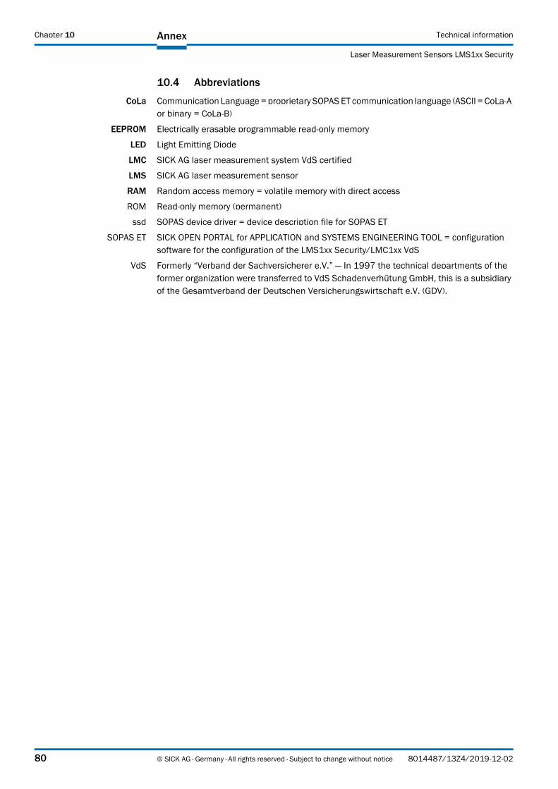
Annex Technical information
Laser Measurement Sensors LMS1xx Security
Chapter 10
10.4 Abbreviations
CoLa Communication Language = proprietary SOPAS ET communication language (ASCII = CoLa-A or binary = CoLa-B)
EEPROM Electrically erasable programmable read-only memory
LED Light Emitting Diode
LMC SICK AG laser measurement system VdS certified
LMS SICK AG laser measurement sensor
RAM Random access memory = volatile memory with direct access
ROM Read-only memory (permanent)
ssd SOPAS device driver = device description file for SOPAS ET
SOPAS ET SICK OPEN PORTAL for APPLICATION and SYSTEMS ENGINEERING TOOL = configuration software for the configuration of the LMS1xx Security/LMC1xx VdS
VdS Formerly “Verband der Sachversicherer e.V.” — In 1997 the technical departments of the former organization were transferred to VdS Schadenverhütung GmbH, this is a subsidiary of the Gesamtverband der Deutschen Versicherungswirtschaft e.V. (GDV).
80 © SICK AG · Germany · All rights reserved · Subject to change without notice 8014487/13Z4/2019-12-02

AnnexTechnical information
Laser Measurement Sensors LMS1xx Security
Chapter 10
10.5 Figures
Fig. 1: Laser output aperture ........................................................................................... 13
Fig. 2: LMS1xx Security/LMC1xx VdS: Ethernet connection using Ethernet cable ...... 15
Fig. 3: Local Area Connection Properties in Windows XP ............................................... 16
Fig. 4: IP address in Windows XP ..................................................................................... 16
Fig. 5: LMC12x VdS with VdS mounting kit 1 — long ...................................................... 27
Fig. 6: LMC13x VdS with VdS mounting kit 2 — short .................................................... 28
Fig. 7: Design of the VdS mounting kits 1 and 2 ............................................................ 29
Fig. 8: Mounting with VdS mounting kit .......................................................................... 30
Fig. 9: LMS12x Security/LMC12x VdS: Position of the electrical connections ............ 33
Fig. 10: LMS13x/LMS14x Security/LMC13x VdS: Position of the electrical connections ............................................................................................................ 36
Fig. 11: Relay outputs of the LMS1xx Security/LMC1xx VdS ........................................... 38
Fig. 12: Example: Connection of alarm output to an object protection system, not resistance monitored ...................................................................................... 38
Fig. 13: Example: Connection of of alarm output to an object protection system, resistance monitored ............................................................................................ 38
Fig. 14: The fault output with optocoupler ........................................................................ 39
Fig. 15: QUICK-START page ................................................................................................... 41
Fig. 16: Selection of the configuration mode .................................................................... 42
Fig. 17: Monitored areas .................................................................................................... 43
Fig. 18: Monitoring fields .................................................................................................... 43
Fig. 19: Field numbers ........................................................................................................ 43
Fig. 20: Response behavior ................................................................................................ 44
Fig. 21: Obstruction protection .......................................................................................... 45
Fig. 22: Start angle and end angle of the contour ............................................................ 46
Fig. 23: Positive and negative distance to the contour .................................................... 47
Fig. 24: Evaluation field for contour as reference ............................................................ 47
Fig. 25: Validity check on the LMC12x/LMC13x ............................................................... 48
Fig. 26: Shaded reference contour field (yellow) at teach-in with pattern field (grey and yellow) .................................................................................................... 52
Fig. 27: Teach-in of field contour with shading ................................................................. 53
Fig. 28: Teach-in of field contour field (green) with shading with pattern field (grey) .... 53
Fig. 29: Operating range of LMS12x/LMS13 Security und LMC12x/LMC13x VdS ........ 69
Fig. 30: Operating range of LMS14x Security ................................................................... 69
Fig. 31: Dimensional drawing LMS12x Security and LMC12x VdS ................................. 70
Fig. 32: Dimensional drawing LMS13x/LMS14x Security and LMC13x VdS .................. 71
Fig. 33: Dimensional drawing LMC12x VdS with VdS mounting kit 1 ............................. 72
Fig. 34: Dimensional drawing LMC12x VdS with VdS mounting kit 2 ............................. 73
Fig. 35: Dimensional drawing LMC13x VdS with VdS mounting kit 2 ............................. 74
8014487/13Z4/2019-12-02 © SICK AG · Germany · All rights reserved · Subject to change without notice 81

Annex Technical information
Laser Measurement Sensors LMS1xx Security
Chapter 10
10.6 Tables
Tab. 1: Variants of the LMS1xx Security/LMC1xx VdS ....................................................... 6
Tab. 2: Software versions ..................................................................................................... 6
Tab. 3: Passwords for LMS1xx Security/LMC1xx VdS .....................................................16
Tab. 4: Items supplied LMS12x, LMS13x and LMS14x Security ....................................17
Tab. 5: Items supplied LMC12x /LMC13x VdS .................................................................18
Tab. 6: Variants of LMS1xx Security/LMC1xx VdS ...........................................................19
Tab. 7: Variants of the LMS12x Security Indoor ...............................................................20
Tab. 8: Variants of the LMS13x Security Outdoor ............................................................20
Tab. 9: Variants of the LMS14x Security Outdoor ............................................................21
Tab. 10: Variants of the LMC12x Vds Indoor ......................................................................21
Tab. 11: Variants of the LMC13x VdS Semi Outdoor .........................................................22
Tab. 12: Input assignments .................................................................................................26
Tab. 13: Required power supply voltages and power drains .............................................31
Tab. 14: LMS12x Security/LMC12x VdS: Terminal assignments (2 x screw terminal block, 14-pin) .........................................................................................................34
Tab. 15: LMS12x Security/LMC12x VdS: Pin assignment of the "Ethernet" connection (4-pin M12 female connector, D-coded) ..............................................................35
Tab. 16: LMS12x Security/LMC12x VdS: Pin assignment of the “AUX” connection (4-pin M8 female connector) .................................................................................35
Tab. 17: LMS13x/LMS14x Security/LMC13x VdS: Pin assignment of the "Power" connection (5-pin M12 male connector, A-coded) ..............................................36
Tab. 18: LMS13x/LMS14x Security/LMC13x VdS: Pin assignment of the "Inputs" connection (8-pin M12 male connector, A-coded) ..............................................37
Tab. 19: LMS13x/LMS14x Security/LMC13x VdS: Pin assignment of the "Alarm" connection (8-pin M12 female connector, A-coded) ...........................................37
Tab. 20: LMS13x/LMS14x Security/LMC13x VdS: Pin assignment of the "Ethernet" connection (4-pin M12 female connector, D-coded) ...........................................37
Tab. 21: LMS13x/LMS14x Security and LMC13x VdS: Pin assignment of the “AUX” connection (4-pin M8 female connector) .............................................................37
Tab. 22: Required wire cross-sections ................................................................................39
Tab. 23: Standard settings for EasyTeach Field .................................................................50
Tab. 24: Data sheet LMS12x/LMS13x/LMS14x Security and LMC12x/LMC13x VdS ....63
Tab. 25: Variants of the LMS12x Security Indoor ...............................................................75
Tab. 26: Variants of the LMS13x Security Outdoor ............................................................75
Tab. 27: Variants of the LMS14x Security Outdoor ............................................................75
Tab. 28: Variants of the LMC12x VdS Indoor ......................................................................75
Tab. 29: Variants of the LMC13x VdS Outdoor ...................................................................76
Tab. 30: Mounting kits for LMS1xx Security .......................................................................76
Tab. 31: Weather protection hoods for LMS1xx Security ...................................................76
Tab. 32: VdS Mounting kits ..................................................................................................77
Tab. 33: Data cables for connecting the LMS1xx Security/LMC1xx VdS to the host or PC ........................................................................................................................77
82 © SICK AG · Germany · All rights reserved · Subject to change without notice 8014487/13Z4/2019-12-02

AnnexTechnical information
Laser Measurement Sensors LMS1xx Security
Chapter 10
Tab. 34: Cables for LMS13x/LMS14x Security and LMC13x VdS .................................... 78
Tab. 35: Consumables ......................................................................................................... 78
8014487/13Z4/2019-12-02 © SICK AG · Germany · All rights reserved · Subject to change without notice 83

8014
487/
13Z4
/201
9-12
-02
Further locations at www.sick.com
AustraliaPhone +61 3 9457 0600 1800 334 802 – tollfreeE-Mail [email protected]
AustriaPhone +43 22 36 62 28 8-0E-Mail [email protected]
Belgium/LuxembourgPhone +32 2 466 55 66E-Mail [email protected]
BrazilPhone +55 11 3215-4900E-Mail [email protected]
CanadaPhone +1 905 771 14 44E-Mail [email protected]
Czech RepublicPhone +420 2 57 91 18 50E-Mail [email protected]
ChilePhone +56 2 2274 7430E-Mail [email protected]
ChinaPhone +86 20 2882 3600E-Mail [email protected]
DenmarkPhone +45 45 82 64 00E-Mail [email protected]
FinlandPhone +358-9-2515 800E-Mail [email protected]
FrancePhone +33 1 64 62 35 00E-Mail [email protected]
GermanyPhone +49 211 5301-301E-Mail [email protected]
Hong KongPhone +852 2153 6300E-Mail [email protected]
HungaryPhone +36 1 371 2680E-Mail [email protected]
IndiaPhone +91 22 6119 8900E-Mail [email protected]
IsraelPhone +972 4 6881000E-Mail [email protected]
ItalyPhone +39 02 274341E-Mail [email protected]
JapanPhone +81 3 5309 2112E-Mail [email protected]
MalaysiaPhone +6 03 8080 7425E-Mail [email protected]
MexicoPhone +52 (472) 748 9451E-Mail [email protected]
NetherlandsPhone +31 30 2044 000E-Mail [email protected]
New Zealand Phone +64 9 415 0459 0800 222 278 – tollfreeE-Mail [email protected]
Norway Phone +47 67 81 50 00E-Mail [email protected]
PolandPhone +48 22 539 41 00E-Mail [email protected]
RomaniaPhone +40 356 171 120 E-Mail [email protected]
RussiaPhone +7 495 775 05 30E-Mail [email protected]
SingaporePhone +65 6744 3732E-Mail [email protected]
SlovakiaPhone +421 482 901201E-Mail [email protected]
SloveniaPhone +386 591 788 49E-Mail [email protected]
South AfricaPhone +27 11 472 3733E-Mail [email protected]
South KoreaPhone +82 2 786 6321E-Mail [email protected]
SpainPhone +34 93 480 31 00E-Mail [email protected]
SwedenPhone +46 10 110 10 00E-Mail [email protected]
SwitzerlandPhone +41 41 619 29 39E-Mail [email protected]
TaiwanPhone +886 2 2375-6288E-Mail [email protected]
ThailandPhone +66 2645 0009E-Mail [email protected]
TurkeyPhone +90 216 528 50 00E-Mail [email protected]
United Arab EmiratesPhone +971 4 88 65 878E-Mail [email protected]
United KingdomPhone +44 1727 831121E-Mail [email protected]
USAPhone +1 800 325 7425 E-Mail [email protected]
VietnamPhone +84 945452999E-Mail [email protected]
SICK AG | Waldkirch | Germany | www.sick.com