livox horizon€¦ · overview 7 connectors 8 lidar connector 8 power cable and sync cable 9...
TRANSCRIPT

Livox Horizon
v1.0
2019.10
User Manual

2 © 2019 Livox Tech. All Rights Reserved.
Using this ManualLegend
Warning Important Hints and Tips Explanation
Downloading Documents
Visit the link below to download the latest Livox Horizon User Manual and other documents related to the Livox Horizon.
www.livoxtech.com/horizon
Downloading Livox ViewerVisit the link below to download Livox Viewer.www.livoxtech.com/horizon
Downloading Livox SDKVisit the link below to download the Livox SDK:https://github.com/Livox-SDK
Searching for KeywordsSearch for keywords such as “FOV” and “mount” to find a topic. If you are using Adobe Acrobat Reader to read this document, press Ctrl+F on Windows or Command+F on Mac to begin a search.
Navigating to a TopicView a complete list of topics in the table of contents. Click on a topic to navigate to that section.
Printing this DocumentThis document supports high resolution printing.

© 2019 Livox Tech. All Rights Reserved. 3
Contents
Using this Manual 2Legend 2Downloading Documents 2Downloading Livox Viewer 2Downloading Livox SDK 2
Product Profile 4Introduction 4Product Characteristics 4Overview 7
Connectors 8LiDAR Connector 8Power Cable and Sync Cable 9Ethernet Port 10
Mounting the Livox Horizon 10Effective Field of View (FOV) Range 10Mounting Notice 11Dimensions 12Removing the Self-Dissipation Module 12
Getting Started 14External Power Supply 14Connection 15
Usage 17Coordinates 17Output Data 17Working States & Working Modes 20Dual Return Mode 21IMU 21Livox Viewer 21Software Development Kit (SDK) 26
Storage, Transportation, and Maintenance 26Storage 26Transportation 27Maintenance 27
Troubleshooting 27After-Sales Information 28Appendix 28
Appendix 1 28Appendix 2 29Appendix 3 29
Specifications 30

4 © 2019 Livox Tech. All Rights Reserved.
Product ProfileIntroduction
Livox Horizon (hereinafter referred as “Horizon”) features a long detection distance, high precision, wide field-of-view (FOV), and high reliability, and can be used for multiple applications including autonomous driving, robotics, automated guided vehicles, and unmanned aircrafts, and more.
High FOV Coverage: The Horizon utilizes Livox’s unique non-repetitive scanning technology and multi-laser and multi-APD DL-Pack technology. This ensures a high-density point cloud which is approximately three times more dense than the Livox Mid-40 within the same period.
Wide FOV: Compared with the circular FOV of Livox Mid-40, Horizon has a more rectangular and larger FOV of 81.7° horizontally and 25.1° vertically. The Horizon scans horizontally from nearly top to bottom, increasing its compatibility with algorithms used to process common point cloud data.
Single Return and Dual Return Modes Supported: Horizon can be set to Dual Return mode. In Dual Return mode, Horizon has a point rate of 480,000 points per second, which is twice the amount than in Single Return mode.
High Reliability: The Horizon offers enhanced reliability as the cutting-edge design works normally without rotating internal electronic devices such as the transmitter and receiver. The Horizon has undergone rigorous reliability testing required by the automotive industry. In addition, the Horizon has achieved an IP67 waterproof and dustproof rating under GB 4208-2008 and IEC 60529 standards. Note the included cables do not meet the same standards.
Environmental Adaptation: Even under 100 kilolux conditions, the Horizon boast a low noise rate below 0.01%. Thanks to innovative de-noising algorithms built into the unit, the Horizon is able to effectively reduce the interference of stray lights from other LiDAR sensor. Additionally, with the tag information embedded in the point cloud data of the Horizon, users can quickly identify if a point cloud is a erroneously detected noise.
Built-in IMU Module: The model of the build-in inertial measurement unit (IMU) is BMI088. The IMU module can be enabled or disabled using Livox Viewer or an SDK. The push frequency of the IMU module is 200 Hz.
User-friendly Livox Viewer: Livox Viewer is a Windows software specially designed for Livox LiDAR sensors. It displays and records real-time point cloud data, replays point cloud videos, and analyzes the 3D point cloud data. Users can set product parameters and calibrate extrinsics using Livox Viewer. The simple interface makes Livox Viewer easy to use.
Livox SDK: A software development kit (SDK) is provided to help develop customizable applications using the data acquired from point clouds. Livox SDK supports Windows/Linux/Mac OS/ROS.
• Horizon has a detection range of up to 260 m, which can be reached when the target object reflects 80% or more of light (e.g., grey concrete walls and roads have a reflectivity range from 15% to 30%, while white plaster walls have a reflectivity range from 90% to 99%). (260 m range measured in an environment with a temperature of 25° C (77° F))
• Before using for the first time remove the screen protector from the optical window.
Product Characteristics
The Horizon utilizes Livox’s unique non-repetitive scanning technology and multi-laser and multi-APD DL-Pack technology. This ensures a high-density point cloud which is approximately three times denser than the Livox Mid series within the same period. Over time, the coverage inside the FOV increases

Livox Horizon User Manual
© 2019 Livox Tech. All Rights Reserved. 5
Figure 1.2.2 displays the typical point cloud patterns of the Horizon.
Figure 1.2.1 Point Cloud Allocation of the Horizon within 0.1s (coordinates units: °)
0.1s 0.2s 0.5s
Figure 1.2.2 Point cloud patterns of the Horizon accumulated over an extended period
Figure 1.2.3 displays the FOV coverage of the Horizon compared with other non-Livox LiDAR sensors that use common mechanical scanning methods. The diagram shows that when the integration time is less than 0.1 seconds, the FOV coverage of the Horizon approaches 60%, similar to the 64-line LiDAR sensor. As the integration time increases to 0.5 seconds, the FOV coverage approaches 100%, so almost all areas are illuminated by laser beams.
significantly and reveals more detailed information of the surroundings.
Figure 1.2.1 displays the point cloud allocation of the Horizon inside the FOV within 0.1s. In the center of the FOV, the scanning density is denser with the average spacing of lines being 0.2° (most line spacing is from 0.1° to 0.3°), which is much denser than traditional 64-line LiDAR sensors, in which the spacing of lines is 0.3° to 0.6°. The two circular areas on both sides have a lower scanning density, with an average line spacing of 0.4° (most line spacing is between 0.2° to 0.8°), rivaling traditional 64-lines LiDAR sensors within 0.1s.

Livox Horizon User Manual
6 © 2019 Livox Tech. All Rights Reserved.
Laser Wavelength 905 nm
Laser Safety Class 1 (IEC 60825-1:2014) (Safe for eyes)
Detection Range (@100 klx) 90 m @ 10% reflectivity, 130 m @ 20% reflectivity260 m @ 80% reflectivity
FOV 81.7° (Horizontal) × 25.1° (Vertical)
Distance Random Error (1σ @ 20 m) < 2 cm
Angular Random Error 1σ < 0.05 º
Beam Divergence 0.28° (Horizontal) × 0.03° (Vertical)
Point Rate 240,000 points/s (first or strongest return)480,000 points/s (dual return)
False Alarm Ratio (@100 klx) < 0.01%
• Livox Horizon cannot precisely detect objects which are less than 0.5 m away. In this situation, the serial number of the Livox Horizon displayed on Livox Viewer will change color to warn users. If in use at the time, the SDK can be checked for more information about the warning. The point cloud may distort to a varying extent when the target object is within the range of 0.5 to 3 m. Contact Livox for support if you r equire precise objects detection within this range.
• Tested in an environment at a temperature of 25° C (77° F) with a target object that has a reflectivity of 80%. The actual environment may differ from the testing environment. The figure listed is for reference only.
• The performance of Livox Horizon may decrease in extreme environments, such as those where the temperature is -40° C (-40° F) or 85° C (176° F) or those that cause high vibration.
Table 1.2.1 Point cloud specifications
Figure 1.2.3 The FOV coverage of the Horizon and non-Livox LiDAR sensors using common mechanical scanning methods. The 16-line non-Livox LiDAR sensor has a vertical FOV of 30°, the 32-line non-Livox LiDAR
sensor is 41°, and the 64-line non-Livox LiDAR sensor is 27°.
64 Lines
32 Lines
16 Lines
Livox Horizon
FO
V C
ove
rag
e (%
)
Integration time(s)
0 0.2 0.4 0.6 0.80
20
40
60
80
100
The performance of the scanning method is defined by the FOV coverage, which is calculated as the fraction of FOV illuminated by laser beams. The FOV coverage (C) can be calculated with the following formula:
Refer to the official Livox website for more information about how the FOV coverage is calculated.
C =Total area in FOV
Total area illuminated by laser beams×100%

Livox Horizon User Manual
© 2019 Livox Tech. All Rights Reserved. 7
Overview
Livox Horizon
4
5
1
2
3 6
1. Optical Window The laser passes through the optical window
and scans objects in the FOV.2. Self-Dissipation Module The self-dissipation module is removable. If
it is removed, an external thermal dissipation sys tem is requ i red to ensure tha t the temperature of the LiDAR's shell does not exceed 85° C (185° F). Otherwise, the Horizon may enter the over temperature error status and stop working. The self-dissipation module is not designed to be mounted and detached several times. Only remove the self-dissipation module when necessary.
3. Self-Dissipation Module Screws Seven black M2 screws are used to secure the
self-dissipation module. If the self-dissipation module is detached, make sure to store the screws properly for future use.
4. 1/4 Inch Mounting Hole Can be mounted on a tripod or other bases
outfitted with a 1/4 inch screw.5. LiDAR Connector The LiDAR connector is used to connect
the Livox Converter 2.0. I t a lso can be modif ied by users. Refer to the Cables section for information on signal definition. The operating voltage range is 10 V to 15 V, with a recommended voltage of 12 V. The minimum working voltage should be increased
in a low temperature environment. When the Horizon is connected to the external power source directly, make sure the output voltage range of the external power source is within the working voltage range of the Horizon. When an extension cable is required, make sure to increase the output voltage of the external power source due to the extra voltage reduction. Make sure the maximum voltage does not exceed 15 V. Note that the power cable may generate voltage fluctuation where the voltage exceeds 15 V in some scenarios such as if the power cable is interfered with or other devices connected to another power source in the parallel circuit suddenly power off. In such scenarios, the Horizon may not work normally or may become damaged.
6. Air Inlet/Fan The fan enables airflow to cool the LiDAR.
Make sure there are at least 10 millimeters between the air inlet and the nearest objects.
7. M3 Mounting Holes Make sure to use the correct screws when
mounting. 8. Air Outlet The air outlet allows warm air to exit the self-
dissipation module. Make sure there are at least 10 millimeters between the air outlet and the nearest objects.
78

Livox Horizon User Manual
8 © 2019 Livox Tech. All Rights Reserved.
Livox Converter 2.0
1. LiDAR Connector PortA JAE MX34012NF1 type connector port used to connect to the Horizon. The mating connector is JAE MX34012SF1 LiDAR.
2. Power PortConnects to an external power supply. When the Horizon is connected to Livox Convertor 2.0, users can use a power supply of 9 to 30 V. The connector type is MOLEX 1053313-1102. The mating connector is MOLEX 105307-1202.
3. Ethernet Port
An RJ45 type Ethernet connector is used to connect to Ethernet cables.
4. Sync PortThe 3-pin sync port supports 3.3V LVTTL sync signal input. Refer to Table 2.2.2 for more information. The mating connector of the sync port connector is Famfull 9.510A0-003-1R0, and JST GHR-03V-S is also compatible.
1
2 3 4
ConnectorsLiDAR Connector
Below is more information on the LiDAR connector:
Figure 2.1.1 LiDAR Cable Connector
Pin Signal Type Description Color
1 Power+ Power DC 10-15 V (max 15 V) Blue/white
2 Ground Power Ground Silver bare wire
3 Ethernet_TX+ Output 100BASE-TX, TX+ Orange/white
4 Ethernet_TX- Output 100BASE-TX, TX- Orange
Table 2.1.1 LiDAR Cable Connector Description
43
1211109
21 5
87
6 28
5/11
173
4
612
9
10

Livox Horizon User Manual
© 2019 Livox Tech. All Rights Reserved. 9
Sync signal description
Figure 2.1.2 Sync signal description
*Refer to the Software Development Kit (SDK) section for more information about the sync signal.
5 Ground Power Ground Silver braided wire
6 Sync+ Input RS485_A, Pulse Per Second Grey/white
7 Power+ Power DC 10-15 V (max 15 V) Blue
8 Ground Power Ground Silver bare wire
9 Ethernet_RX+ Input 100BASE-TX, RX+ Green/white
10 Ethernet_RX- Input 100BASE-TX, RX- Green
11 Ground Power Ground Silver braided wire
12 Sync- Input RS485_B, Pulse Per Second Grey
Pulse Per Second(PPS)
t0t1
t0=1s1ms<t1<300ms
秒脉冲(PPS)
t0t1
t0=1s1ms<t1<300ms
Power Cable and Sync CableThe Horizon cables package includes a power cable and sync cable.
Power CableConnect “A” to the power port of the Livox Converter 2.0 and connect “B” to an external DC power supply. The connector type of this power cable is MOLEX 105307-1202.
Figure 2.2.1 Power cable
21
A B500±25 mm
Pin Signal Type Description Color
1 Power+ Power DC 9 - 30 V (max 30 V) Red
2 Ground Power Ground Black
Table 2.2.1 Power cable description

Livox Horizon User Manual
10 © 2019 Livox Tech. All Rights Reserved.
Pin Signal Type Description Color
1 Ground Power Ground Black
2 Sync+ Input 3.3 V LVTTL, Pulse Per Second Blue
3 Reserved Reserved Undefined White
Table 2.2.2 Sync cable description
Sync cableConnect “A” into the sync port of the Livox Converter 2.0 and connect “B” to the sync signal. The sync cable has a 3-pin connector. The connector type is Famfull 9.510A0-003-1R0, which is compatible with JST GHR-03V-S type connectors. Refer to the Data Synchronization section for more information.
Figure 2.2.2 Sync cable
Ethernet PortThe Livox Converter 2.0 supports 100BASE-TX standard RJ45 Ethernet port. The Horizon uses two twisted pairs to send and receive data.
1A B
23
500±25 mm
Mounting the Livox HorizonEffective Field of View (FOV) Range
As shown below, the Horizon has a FOV of 81.7° horizontally and 25.1° vertically. When mounting a Livox Mid Series LiDAR sensor, make sure that the FOV is not blocked by any objects. Visit www.livoxtech.com/horizon to download the 3D models of the Horizon and its FOV.
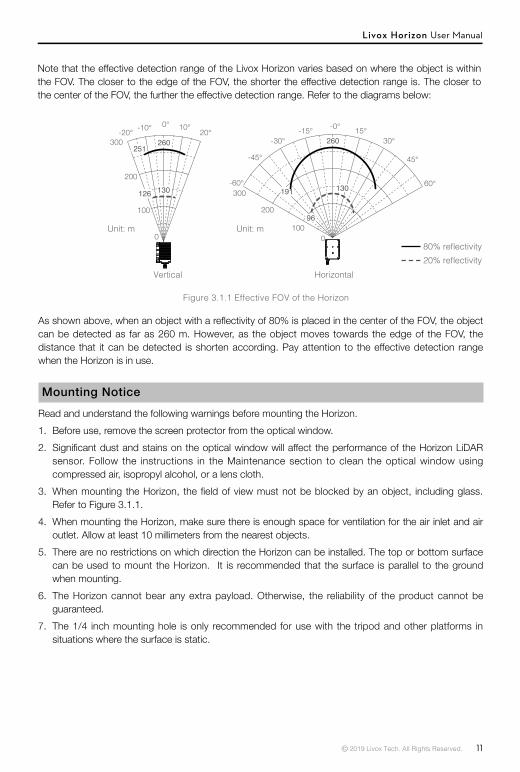
Figure 3.1.1 Effective FOV of the Horizon
Horizontal FOVVertical FOV
50.1mm
25.1° 81.7°
Livox Horizon User Manual
© 2019 Livox Tech. All Rights Reserved. 11
Figure 3.1.1 Effective FOV of the Horizon
Note that the effective detection range of the Livox Horizon varies based on where the object is within the FOV. The closer to the edge of the FOV, the shorter the effective detection range is. The closer to the center of the FOV, the further the effective detection range. Refer to the diagrams below:
As shown above, when an object with a reflectivity of 80% is placed in the center of the FOV, the object can be detected as far as 260 m. However, as the object moves towards the edge of the FOV, the distance that it can be detected is shorten according. Pay attention to the effective detection range when the Horizon is in use.
Mounting NoticeRead and understand the following warnings before mounting the Horizon. 1. Before use, remove the screen protector from the optical window. 2. Significant dust and stains on the optical window will affect the performance of the Horizon LiDAR
sensor. Follow the instructions in the Maintenance section to clean the optical window using compressed air, isopropyl alcohol, or a lens cloth.
3. When mounting the Horizon, the field of view must not be blocked by an object, including glass. Refer to Figure 3.1.1.
4. When mounting the Horizon, make sure there is enough space for ventilation for the air inlet and air outlet. Allow at least 10 millimeters from the nearest objects.
5. There are no restrictions on which direction the Horizon can be installed. The top or bottom surface can be used to mount the Horizon. It is recommended that the surface is parallel to the ground when mounting.
6. The Horizon cannot bear any extra payload. Otherwise, the reliability of the product cannot be guaranteed.
7. The 1/4 inch mounting hole is only recommended for use with the tripod and other platforms in situations where the surface is static.
80% reflectivity20% reflectivity
HorizontalVertical
0100
200
300
0
100
200
300-20° -10° 0° 10° 20°
-60°
-45°
-30°-15° -0° 15°
30°
45°
60°
Unit: m Unit: m

Livox Horizon User Manual
12 © 2019 Livox Tech. All Rights Reserved.
Figure 3.3.1 Removing the Self-Dissipation Module
Removing the Self-Dissipation ModuleThe self-dissipation module is located at the bottom of the Horizon. Users are allowed to detach the self-dissipation module. Before doing so, make sure to prepare an alternative dissipation system so that the Horizon can work properly without the self-dissipation module. Otherwise, the highest working temperature of the Horizon may be decreased when the self-dissipation module is detached. The self-dissipation module is not designed to be mounted and detached several times. Only remove the self-dissipation module if necessary.
To remove the self-dissipation module, make sure the bottom of the Horizon is facing upward, and remove the seven black M2 screws using the hex screwdriver included. Detach the self-dissipation module. Make sure the connectors on the bottom of the Horizon and the self-dissipation module are aligned, and secure the self-dissipation module using seven black M2 screws. When the self-dissipation module is detached, make sure to attach the provided rubber seal to the fan connector on the bottom of the Livox Horizon to prevent liquids or dust from coming into contact with the Livox Horizon.
Dimensions
Livox Horizon (with the self-dissipation module)The top surface of the Horizon has six M3 mounting holes with a depth of 6 mm while the bottom surface has four M3 mounting holes with a depth of 6 mm. Make sure all the screws have been secured with a depth deeper than 4 mm. The center of the bottom surface of the Horizon has a 1/4 inch mounting hole. The Horizon can be attached to the tripod using this hole. Note that this 1/4 inch mounting hole is only used in situations where the surface is static.
37.0
1/4-20 UNC 115.
0
71.622.0
27.0
56.0
27.0
15.4
66.5
50.1
4-M3 6
37.5
7.0
63.0
35.5
60.00
4.0+0.05 0
+0.1 0
2
4.06.0
6-M3 6
50.1
77.0
84.1

Livox Horizon User Manual
© 2019 Livox Tech. All Rights Reserved. 13
Unit: mm
Unit: mm
Figure 3.4.2 The Horizon Dimensions without Self-Dissipation Module (refer to Appendix 2)
Weight (with cable) Approx. 1180 g (Built-in cable length: Aprox. 1.5 m, weight: 150 g)
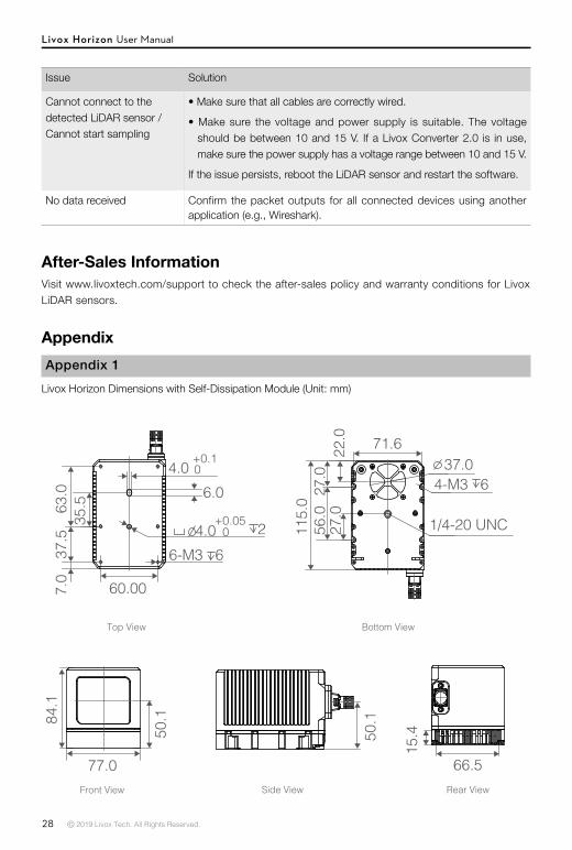
Dimensions 77 × 115 × 84 mm
Table 3.4.1 The Horizon Weight & Dimensions (with self-dissipation module)
Table 3.4.2 The Horizon Weight & Dimensions (without self-dissipation module)
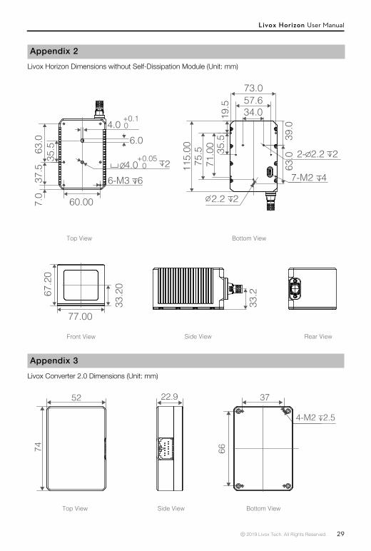
Weigh (with cable) Approx. 1010 g
Dimensions 77 × 115 × 67 mm
37.0
1/4-20 UNC 115.
0
71.622.0
27.0
56.0
27.0
15.4
66.5
50.1
4-M3 6
37.5
7.0
63.0
35.5
60.00
4.0+0.05 0
+0.1 0
2
4.06.0
6-M3 6
50.1
77.0
84.1
Figure 3.4.1 The Horizon Dimensions with Self-Dissipation Module (refer to Appendix 1)
Livox Horizon (without the self-dissipation module)The six M3 mounting holes with a depth of 6 mm on the top surface of the Horizon can be used to secure the Horizon when the self-dissipation module is detached.
33.2
0
67.2
0
77.00
73.057.6
2.2 2
2- 2.2 2
19.5
71.0
0 35.5
75.5
63.0
39.0
115.
00
34.0
7-M2 4
33.2
37.5
7.0
63.0
35.5
60.00
4.0+0.05 0
+0.1 0
2
4.06.0
6-M3 6

Livox Horizon User Manual
14 © 2019 Livox Tech. All Rights Reserved.
Weight Approx. 88 g
Dimensions 74 × 52 × 23 mm
Table 3.4.3 Livox Converter 2.0 Weight & Dimensions
Livox Converter 2.0Refer to the dimensions below to mount the Livox Converter 2.0.
7452 22.9 37
66
4-M2 2.5
Figure 3.4.3 Livox Converter 2.0 Dimensions (refer to Appendix 3)
Getting StartedExternal Power Supply
The working voltage range of the Horizon is from 10 to 15 V. When an extension cable is required, make sure to increase the output voltage of the external power source due to the extra voltage reduction. Make sure the maximum voltage does not exceed 15 V. The minimum working voltage should be increased in a low temperature environment. Note that the power cable may generate voltage fluctuation where the voltage exceeds 15 V in some scenarios such as if the power cable is interfered with or other devices connected to another power source in the parallel circuit suddenly power off. In such situations, the Horizon may work normally or may even become damaged.
Normally, the working power of the Horizon is 12 W. In an environment where the temperature is from -40° to -20° C (–40° to -4° F), the Horizon will first enter self-heating mode, which lasts at least three minutes. In self heating mode, the working power of the Horizon may reach up to 42 W. The working power of the Horizon varies at different temperature. Below shows the relationship between the temperature of the environment and the working power of the Horizon.
Figure 4.1.1 The working power of the Horizon at varying temperatures
Temperature (° C)
Pow
er (W
)
Without self-dissipation module
With self-dissipation module
-30 10-40 5020 40 60
13w12w
70300-10
45
0510152025303540
-20 80 85
Unit: mm

Livox Horizon User Manual
© 2019 Livox Tech. All Rights Reserved. 15
Figure 4.2.1 Connecting using static IP address
Connection
The Horizon uses a compact and reliable electrical connector for power supply as well as control signal and data transmission. Refer to the Cables section for more information about the connector. The Livox Converter 2.0 integrates a LiDAR port, a sync port, a power port, and an Ethernet port. To ensure optimal performance, it is recommended to always use a Livox Converter 2.0.
The Horizon supports two IP modes: dynamic IP address mode and static IP address mode. All Horizon LiDAR sensors are set to static IP address mode by default with an IP address of 192.168.1.1XX (XX stands for the last two digits of the Livox Horizon LiDAR sensor’s serial number). The default subnet masks of the Livox Horizon LiDAR sensors are all 255.255.255.0, and their default gateways are 192.168.1.1. Directly connect the Livox Horizon to the computer before using for the first time. The static and dynamic IP addresses are connected in different ways. 1.The static IP address is connected by default and in this mode, the Horizon can be connected to a computer directly. 2. To connect to the dynamic IP address, make sure the Horizon is switched to dynamic IP mode by using the Livox Viewer or SDK. In dynamic address mode, the addresses are assigned to the Horizon using dynamic host configuration protocol (DHCP).
Static IP address :
1. Follow the steps to set the IP address of your computer to static IP address:
Windows system
a. Click to enter in the Network and Sharing Center under Control Panel.
b. Click the network you are using, and click “Properties”.
c. Double click “Internet Protocol Version 4 (TCP/IPv4)”.
d. Set the static IP address of the computer to 192.168.1.50 and the subnet mask to 255.255.255.0. Click “OK” to complete.
Ubuntu-16.04 system
The IP address of the computer can be configured by using the ifconfig command at the terminal. The configuration code is as below:
~$ sudo ifconfig enp4s0 192.168.1.50 (replace “enp4s0” with the network port name of the computer)
2. Connect the Horizon, Livox Converter 2.0, external power source, and computer by following Figure 4.2.1.
Livox Converter
Livox HorizonExternal Power Suppply
Ethernet Cable

Livox Horizon User Manual
16 © 2019 Livox Tech. All Rights Reserved.
Figure 4.2.2 Connecting using dynamic IP address
a. Connect the Horizon to the Livox Converter 2.0.
b. Connect the computer and the Livox Converter 2.0 to the router using Ethernet cables. Make sure both the Livox Converter 2.0 and the computer are connected to the LAN port on the router.
c. Connect the Livox Converter 2.0 to an external power source.
Dynamic IP address:
1. Follow Figure 4.2.1 to connect the Horizon, Livox Converter 2.0, external power source, and computer.
2. Run Livox Viewer, click to open settings page, and set the IP address of the Horizon to dynamic IP address.
3. Disconnect the Horizon, Livox Converter 2.0, external power source, and computer.
4. Follow the steps to set the IP address of your computer to dynamic IP address:
Windows system
a. Click to enter the Network and Sharing Center under Control Panel.
b. Click the network you are using, and click “Properties”.
c. Double click “Internet Protocol Version 4 (TCP/IPv4)”.
e. Select “Obtain an IP address automatically” and “Obtain DNS server address automatically”, then click “OK” to complete.
Ubuntu-16.04 system
a. Click to open “Network”.
b. Click “IPv4”, and then click “Automatic (DHCP)”. Click “Apply” to complete.
5. Connect the Horizon, Livox Converter 2.0, router, computer, and external power supply by following Figure 4.2.2.
Livox Horizon
External Power Suppply
Router with DHCPEthernet Cable
• If multiple Horizon LiDAR sensors are set to static IP addresses, make sure all the Horizon LiDAR sensors have different IP addresses and use a switchboard to connect them to the computer.
• Launch Livox Viewer after the Horizon is connected. Click the device that the static IP address should be altered. Click to open settings page and set the static IP address of the Horizon.
• If more than six Horizon LiDAR sensors are required, use a kilo mega switchboard. Otherwise, data may get lost and there may be connection failures.
a. Connect the Horizon to the Livox Converter 2.0.
b. Connect the Livox Converter 2.0 to your computer using an Ethernet cable.
c. Connect the Livox Converter 2.0 to an external power source.

Livox Horizon User Manual
© 2019 Livox Tech. All Rights Reserved. 17
• If more than six Horizon LiDAR sensors are required, use a kilo mega router.• The broadcast number for each LiDAR sensor can be viewed in the Device Manager of Livox
Viewer or the SDK. For the Horizon, the broadcast number will be its serial number ending in an additional “1”.
UsageCoordinates
The Horizon has a built-in IMU. The coordinates of the point cloud O-XYZ and of the IMU O'-X'Y'Z' are defined as below:
Figure 5.1.1 Coordinates of the Horizon
Figure 5.2.1.1 Relationship between Cartesian coordinates and Spherical coordinates
Output DataThe output information of Livox Horizon LiDAR sensors includes point cloud data and IMU data. Both point cloud data and IMU data have timestamp and status codes, while point cloud data also has the target reflectivity, coordinates and tag information.
Point Cloud DataA point cloud is the collection of the points where the surface of an object was detected in the FOV of the LiDAR sensor. Each point contains the following information.
Target reflectivity: 0 to 255. 0 to 150 corresponds to the reflectivity within the range of 0 to 100% in the Lambertian reflection model. 151 to 255 corresponds to the reflectivity of target objects with retroflection properties.
Coordinates: Can be expressed as Cartesian coordinates (x, y, z) and Spherical coordinates (r, θ, φ). The relationship between Cartesian and Spherical coordinates is shown in the figure below. When there is no object within the detective range or the object is placed beyond the detective range, the coordinates of the point cloud will be expressed as (0, 0, 0) in Cartesian coordinates while as (0, θ, φ) in Spherical coordinates.
50.1mm
Z
Y
X X
Z
X
Y
Z
M
P(r,θ,φ)
o
θ
φ
Y
81.7°
25.1°
给出定义坐标系下IMU坐标为:(-55.12,-22.26,29.70)
The origin O' of IMU coordinates is defined in the point cloud coordinates as (-55.12, -22.26, 29.70) (Unit: mm).
x= r×sin(θ)×cos(φ)y = r×sin(θ)×sin(φ)z = r×cos(θ)
50.1
mm
Z
Y
X X
Z
X
Y
Z
M
P(r,θ,φ)
o
θ
φ
Y
81.7
°
25.1
°
X'Y'
Z'
oX
Z
Y
o'

Livox Horizon User Manual
18 © 2019 Livox Tech. All Rights Reserved.
Tags: Indicates the return type of the laser and if the point detected is a noise. The format of the tag is as shown below:
bit7 bit6 bit5 bit4 bit3 bit2 bit1 bit0Reserved Return number:
00:return 0 01:return 110:return 211:return 3
Point property based on intensity:00:Normal01:High confidence level of the noise 10:Moderate confidence level of the noise 11:Reserved
Point property based on spatial position:00:Normal01:High confidence level of the noise10:Moderate confidence level of the noise11:Low confidence level of the noise
Each tag is composed of one byte. In this byte, bit7 and bit6 are Group 1, bit5 and bit4 are Group 2, bit3 and bit2 are Group 3 while bit1 and bit0 are Group 4.
Group 2 indicates the return sequence of the sampling point. Featuring a coaxial optical path, the Horizon itself will generate a laser return even if there is no detectable object around. This return is recorded as return 0. After that, if there is any object within the detectable range, the first laser that returns to the Horizon is recorded as return 1, and then return 2, and so on. If the object is too close to the Horizon such as 1.5 m away, the first effective return will be merged into return 0, and be recorded as return 0.
Group 3 indicates if the sampling point is a noise based on the intensity of the return. Normally, the intensity of the returns of the noises generated due to the interference of atmosphere particles such as dust, rain, fog, and snow is quite low. Therefore, the noises are divided into two categories based on the intensity of the return received: "01" stands for low intensity of the return, indicating that the samples have a high possibility of being noises such as dust; "10" stands for moderate intensity of the return, indicating that the samples have a moderate possibility of being noises such as rain and fog. The lower the confidence level of the sample is, the lower the possibility that it being a noise is.
Group 4 indicates if the sampling point is a noise based on its spatial position. Normally, when the Horizon LiDAR sensors detect two close objects, there will be some thread-like noises between the two objects. The noises are divided into three categories. The lower the confidence level of the noise is, the lower the possibility that it being a noise is.
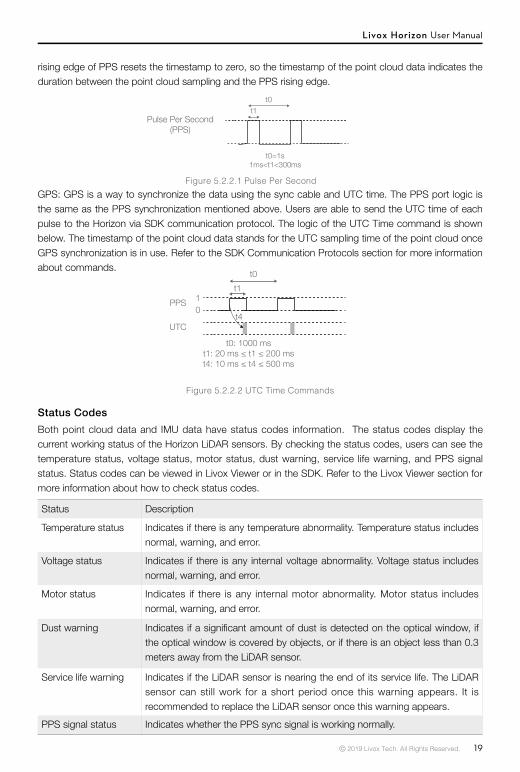
TimestampBoth point cloud data and IMU data have timestamp information. There are three ways to synchronize data with the Horizon: IEEE 1588-2008, Pulse Per Second (PPS) and GPS (PPS+UTC).
IEEE 1588-2008: IEEE 1588-2008 is the Precision Time Protocol (PTP) enabling precise synchronization of clocks in measurement and control systems by Ethernet. Livox LiDAR sensors, as the ordinary clock in the PTP, only supports UDP/IPV4 for PTP. Livox LiDAR sensors support the following message events: Sync, Follow_up, Delay_req, Delay_resp.
PPS: PPS uses the sync cable for data synchronization. Refer to the Cables section for more information. The synchronization logic is shown in the figure below. The pulse interval in PPS is 1s (t0 = 1 s) while the continuous time of high-level voltage is from 1 ms to 300 ms (1 ms <t1< 300ms). The
Livox Horizon User Manual
© 2019 Livox Tech. All Rights Reserved. 19
rising edge of PPS resets the timestamp to zero, so the timestamp of the point cloud data indicates the duration between the point cloud sampling and the PPS rising edge.
Pulse Per Second(PPS)
t0t1
t0=1s1ms<t1<300ms
秒脉冲(PPS)
t0t1
t0=1s1ms<t1<300ms
Figure 5.2.2.1 Pulse Per Second
Figure 5.2.2.2 UTC Time Commands
GPS: GPS is a way to synchronize the data using the sync cable and UTC time. The PPS port logic is the same as the PPS synchronization mentioned above. Users are able to send the UTC time of each pulse to the Horizon via SDK communication protocol. The logic of the UTC Time command is shown below. The timestamp of the point cloud data stands for the UTC sampling time of the point cloud once GPS synchronization is in use. Refer to the SDK Communication Protocols section for more information about commands.
PPS
UTC
10
t0t1
t4
t0: 1000 mst1: 20 ms ≤ t1 ≤ 200 mst4: 10 ms ≤ t4 ≤ 500 ms
Status Description
Temperature status Indicates if there is any temperature abnormality. Temperature status includes normal, warning, and error.
Voltage status Indicates if there is any internal voltage abnormality. Voltage status includes normal, warning, and error.
Motor status Indicates if there is any internal motor abnormality. Motor status includes normal, warning, and error.
Dust warning Indicates if a significant amount of dust is detected on the optical window, if the optical window is covered by objects, or if there is an object less than 0.3 meters away from the LiDAR sensor.
Service life warning Indicates if the LiDAR sensor is nearing the end of its service life. The LiDAR sensor can still work for a short period once this warning appears. It is recommended to replace the LiDAR sensor once this warning appears.
PPS signal status Indicates whether the PPS sync signal is working normally.
Status CodesBoth point cloud data and IMU data have status codes information. The status codes display the current working status of the Horizon LiDAR sensors. By checking the status codes, users can see the temperature status, voltage status, motor status, dust warning, service life warning, and PPS signal status. Status codes can be viewed in Livox Viewer or in the SDK. Refer to the Livox Viewer section for more information about how to check status codes.

Livox Horizon User Manual
20 © 2019 Livox Tech. All Rights Reserved.
Working states Description
Initializing The LiDAR sensor is powering on.
Normal The LiDAR sensor is powered on and working normally.
Standby The LiDAR sensor is powered on, but the laser beams are not active.
Power saving All components are powered off apart from the communication module.
Error The LiDAR sensor will enter error status when an error is detected and all the components are powered off apart from the communication module.
Working States & Working ModesThe working states of the Livox Horizon includes initializing, normal, standby, power saving, and error.
The Horizon also has three working modes: Normal, Standby, and Power Saving. These modes can be set in Livox Viewer and SDK.
Figure 5.3.1 Relationship between the different working states
Power saving
Initializing
Error
StandbyNormal
Figure 5.3.2 Relationship between the different working modes available in Livox Viewer
Power saving
StandbyNormal
Livox Horizon User Manual
© 2019 Livox Tech. All Rights Reserved. 21
Dual Return Mode
The Horizon can be set to Dual Return mode using Livox Viewer or SDK. The Horizon can generate a point cloud of up to two returns in Dual Return mode, which has a point rate of 480,000 points per second.
To set the return mode, run Livox Viewer after the Horizon is connected. Click the desired device under the device manager page. Click to select the return mode.
IMU
Horizon has a built-in IMU providing the altitude data of the Horizon.
The push frequency of the IMU can be set using Livox Viewer or SDK. Setting the IMU push frequency is the same as setting the return mode of the LiDAR sensor.
Livox Viewer
Livox Viewer is a computer software designed for Livox LiDAR sensors and Livox Hub. Users can check real-time point cloud data of all the Livox LiDAR sensors connected to a computer, and also record the point cloud data to view offline or for future application use. The simple interface makes it easy to use.
Visit www.livoxtech.com to download the latest Livox Viewer. Livox Viewer supports WINDOWS®7/8/10 (64 bit) and UBUNTU®16.04 (64 bit).
• For Windows users, turn off firewalls on your computer before using Livox Viewer. Otherwise, Livox Viewer may not be able to detect the Livox LiDAR sensors. Make sure the graphics driver is correctly installed. Otherwise, Livox Viewer may not launch or may crash.
For Windows users: unzip the Livox Viewer file and click to open the .exe file named “Livox Viewer.”
For Ubuntu users: unzip the Livox Viewer file and click to open the “./livox_viewer.sh” file under the root directory.

Livox Horizon User Manual
22 © 2019 Livox Tech. All Rights Reserved.
Livox Viewer Homepage
5.7.1 Livox Viewer Homepage
File: Click “Open File” to open a saved point cloud data file in .lvx format. Click “Open Device Manager” to open the Device Manager to scan and detect the connected LiDAR sensors. Click” Save as->.las file” to save the point cloud data in .las format. Click “Save as->.csv file” to save the point cloud data in CSV format. Click “Clear” to remove the point cloud data.
Tools: Click “Grid Property” to set the grid type, color, and coordinates. Click “Device Settings” to check the parameters of current device, and set the parameters. Click “Firmware Update” to update the firmware of Livox LiDAR sensors and Livox Hub. Click “Extrinsic Parameter Tool” to import extrinsics. Click “Lvx to Las Tool” to allow users to convert .lvx format files into .las format. Note that when clicking “Lvx to Las Tool”, the whole .lvx file will be converted to a .las file which contains only one point cloud image. The .lvx file cannot be converted to .las files frame by frame. Click “Options” to set the file path to record point cloud data, select the way to color the point cloud and enable some advanced functions.
Net Adapter: Select the internet connection.
Help: Click for more information about Livox Viewer.
: Click to open a saved point cloud data file in .lvx format.
: Click to open the Device Manager to search for all the Livox LiDAR sensors and Livox Hubs in the LAN.
: Click to open the Settings to check the parameters of current device and set the parameters.
: Click to open the Lvx Manager when displaying the saved point cloud data.
: Click this to open the spreadsheet to pick a certain area of the point cloud, and check the detailed information of this selected area of the point cloud.
: Click to display or hide the grid. Livox Viewer displays a virtual grid composed of 13 concentric circles. The first 10 concentric circles, which are equally distanced, show the distance from 10 m to 100 m. The 11th, 12th, and 13th circles show the distance of 150 m, 200 m, and 300 m.
: Click to automatically adjust the position of the point cloud on the grid so that the point cloud can be viewed clearly.
: Click to choose the angle view. Choose from right view, front view, top view, and back view. The angle view can be manually adjusted using the mouse and keyboard.
a. Zoom in or out using the mouse wheel.
Livox Horizon User Manual
© 2019 Livox Tech. All Rights Reserved. 23
b. Hold the left mouse button and move the mouse to adjust the angle view.
c. Press “Ctrl” on the keyboard, hold the left mouse button, and move the mouse to rotate the point cloud.
d. Press “Shift” on the keyboard, hold the left mouse button, and move the mouse to move the grid.
e. Hold the right mouse button and move the mouse to zoom in and out the point cloud.
: Display or hide the color bar. The color bar works as a reference of the point cloud data. You can set to display the color bar according to the color depth or the reflectivity.Color: reflectivity : Click to select the way to color the point cloud. Users can select solid color or set based on reflectivity or LiDAR ID. Note that by default the point cloud will be colored based on reflectivity.Point Size 1px : Click to set the point size. Choose from 1 px, 2 px, 3 px, 4 px, and 5 px. It is recommended to select 2 px.
Viewer controls:
: Click to rewind to the beginning (not available when checking real-time point clouds).
: Click to fast forward to the end (not available when checking real-time point clouds).
: Click to rewind by one frame (not available when checking real-time point clouds).
: Click to fast forward by one frame (not available when checking real-time point clouds).
: Click to play or pause.
: When one or more Livox LiDAR sensors are connected, click to start recording the live data. Click again to stop recording.
Frame Time 100ms : Click to set the frame time: Click to set the frame time. Choose from 50, 100, 200, 500, 1000, and 3000 ms. The longer the frame time is, the denser the point cloud will be. The recommended frame time for Livox Horizon is 200 ms.
Playback Speed 4.0x : Click to set the frame speed. Choose from x0.5, x1.0, x2.0, and x4.0 (not available when checking real-time point clouds).
00:00:00/00:00:00 Drag to adjust the time of the saved point cloud data file (not available when checking real-time point clouds).
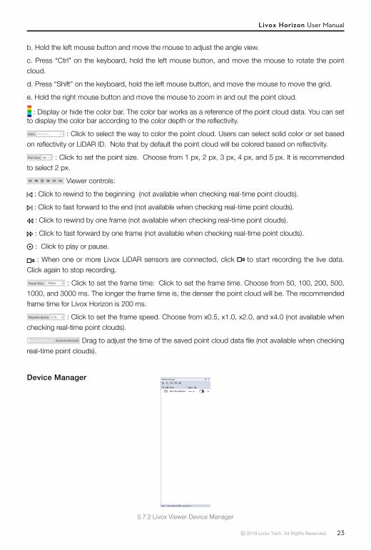
Device Manager
5.7.2 Livox Viewer Device Manager

Livox Horizon User Manual
24 © 2019 Livox Tech. All Rights Reserved.
: Connect all devices.
: Disconnect all devices.
: Display the point cloud data of all connected LiDAR sensors.
: Hide the point cloud data of all connected LiDAR sensors.
: Click to sort all connected LiDAR sensors by their broadcast numbers.
Note that the two icons mentioned can only display or hide the point cloud data displayed in Livox Viewer, but they will not enable or disable the LiDAR sensors by sampling point cloud data.
Lidar Hub : Select the type of device you would like to check.
: Displays all the devices in the LAN.
: Check the working states. When in error state, users can check the status codes.
: Display or hide the point cloud of the selected Livox LiDAR sensor.
: Click to connect or disconnect the selected Livox LiDAR sensor.
Checking Real-Time Point Cloud Data1. Connect the Livox LiDAR sensor, and run Livox Viewer. Click to open Device Manager. The Device
Manager will display all the devices in the LAN.
2. Select LiDAR in Device Manager.
3. Select a Livox LiDAR sensor to check, and click to connect. Alternatively, select the Livox LiDAR sensor, right click, and click “Connect Device”. Click to connect all Livox LiDAR sensors.
4. After connecting, click to view the point cloud data.
Recording Point Cloud DataWhen one or more Livox LiDAR sensors are connected, click to start recording the live data. Click again to stop recording.
Displaying Saved Point Cloud DataClick or click File > “open file” to open the saved point cloud data. Use the viewer controls to adjust the video. While displaying saved point cloud data, you can click on the homepage. The Lvx Manager window will appear. You can click to hide or display the selected Livox LiDAR sensor.
Extrinsics CalibrationFollow the steps below to import the extrinsics when necessary.
Click Tools > Extrinsic Parameter Tool to enter the Extrinsic Parameter Tool page.Make sure the format of the code in the extrinsics import page matches the example below:

Livox Horizon User Manual
© 2019 Livox Tech. All Rights Reserved. 25
In the example above, “1HDDG6U00100201” represents the broadcast code of the Livox LiDAR sensor. Click “Start Cali” to check the coordinates of all the Livox LiDAR sensors connected. Users can manually enter each coordinate.
Alternatively, select a coordinate and use the wheels at the bottom of the screen to adjust the coordinates. Press “Ctrl” when using the wheels to select multiple coordinates in the same column to adjust them simultaneously.
Click “Load From File” to import extrinsics.
Click “Read From Device” to check the current coordinates of all Livox LiDAR sensors. All Livox LiDAR sensors can store extrinsics. Storing extrinsics will not affect the real-time point cloud data. Refer to the Software Development Kit (SDK) section for more information.
Click “Save Param As” to save the coordinates of all detected Livox LiDAR sensors
Click “Apply” to confirm the new coordinates. A pop-up window will appear. Choose to write the current extrinsics to the Livox LiDAR sensor. Otherwise, there will be no change in the coordinates.
• The new coordinates will only be effective after you click Apply. • For more information regarding the extrinsic parameters, refer to the SDK Communication Protocol.
Switching the Angle ViewClick the following buttons to change the angle view of the point clouds:
Right View Front View Top View Back View
Alternatively, the angle view can also be adjusted using a mouse and keyboard.
a. Zoom in or out using the mouse wheel.
b. Hold the left mouse button and move the mouse to adjust the angle view.
c. Press “Ctrl” on the keyboard, hold the left mouse button, and move the mouse to rotate the point cloud.
d. Press “Shift” on the keyboard, hold the left mouse button, and move the mouse to move the grid.
e. Hold the right mouse button and move the mouse to zoom in and out the point cloud.

Livox Horizon User Manual
26 © 2019 Livox Tech. All Rights Reserved.
Make sure the computer is connected to the internet when downloading the firmware. Once the firmware is downloaded, an internet connection is no longer required.
Software Development Kit (SDK)Besides using Livox Viewer to check real-time point cloud data, users can also use the SDK or the ROS to apply the point cloud and IMU data acquired from Livox LiDAR sensors to different scenarios.
SDK Communication Protocol
With the SDK Communication Protocol, users can learn how to customize the Livox LiDAR sensors. The SDK Communication Protocol encompasses the following three types of data:
Control Command Data: Configuration and query of LiDAR parameters and status information.
Point Cloud Data: Point cloud data generated by LiDAR.
IMU Data: IMU data generated by the built-in IMU.
All data is stored in little-endian format.
Visit http://www.livoxtech.com/sdk to learn more information about SDK communication protocol, Livox SDK API reference, and ROS Toolkit.
Storage, Transportation, and MaintenanceStorage
The storage temperature range for the Livox Horizon is from -40° to 85° C (-40° to 185° F). Keep Livox Horizon LiDAR sensors in a dry and dust-free environment.• Make sure the Horizon LiDAR sensors are not exposed to environments containing poisonous or
corrosive gases or materials. • DO NOT drop Livox Horizon LiDAR sensors and be careful when placing a LiDAR sensor in storage or
taking it out of storage.
Firmware UpdateThe firmware of Livox LiDAR sensors and Livox Hub can be updated by using Livox Viewer. To update the firmware, follow the steps below:1. Click Tools > Firmware Update. A page will appear displaying all connected devices.2. Select “Lidar Update” under Update Mode to display all detected Livox LiDAR sensors.3. Click “Check Firmware” to check the current firmware version of the selected Livox LiDAR sensors.4. Select the firmware version under “Firmware Version”, and click “Download” to download the
firmware to the computer. 5. After downloading the file, select the Livox LiDAR sensor you wish to update under “Firmware
Update” and click “…” to select the downloaded firmware.6. Click “Start” to update the firmware of the selected Livox LiDAR sensor.7. The Livox LiDAR sensor will restart and reconnect to the computer after the update. Repeat the
steps above if the update fails.

Livox Horizon User Manual
© 2019 Livox Tech. All Rights Reserved. 27
• If a Horizon LiDAR sensor is not to be used for more than three months, regularly check the sensors and connectors for abnormalities.
TransportationBefore transportation, place Livox Horizon LiDAR sensors in a suitable box for transportation and make sure it is secure.
Make sure to place foam inside the transportation box and that the box is clean and dry.
DO NOT drop Horizon LiDAR sensors and always be careful when carrying a LiDAR sensor.
MaintenanceIn normal conditions, the only maintenance required for the Livox Horizon is to clean the optical window of the LiDAR sensor. Dust and stains on the optical window can negatively affect the performance of the LiDAR sensor.
First, check the surface of the optical window to see if cleaning is necessary. If it is necessary to clean, follow the steps below:
1. Use compressed or canned air:DO NOT wipe a dusty optical window, as it will only cause more damage. Dust the optical window with compressed or canned air before wiping the optical window. Note that if the optical window has no visible stains afterward, it is not necessary to wipe it also.
2. Wipe the stains:DO NOT wipe using a dry lens tissue, as it will scratch the surface of the optical window.If the optical window is still dirty, a mild soap solution can be used to gently wash the window. Repeat Step 2 to remove any remaining soap residue.
Issue Solution
Cannot detect the LiDAR sensor
• Make sure that all cables are correctly wired.• Make sure the voltage and power supply is suitable. The voltage
should be between 10 and 15 V. If a Livox Converter 2.0 is in use, make sure the power supply has a voltage range between 10 and 15 V.
• Make sure that the LiDAR sensor is not connected to other software.• Make sure the LAN is selected.• Make sure no security software is installed that would block Ethernet
broadcasts.If the issues persists, try to turn off all firewalls and search again. Confirm the packet outputs for all connected devices using another application (e.g., Wireshark).
TroubleshootingThe table below shows you how to troubleshoot and resolve common issues with Livox Horizon LiDAR sensors. If the issue persists, please contact Livox.
Livox Horizon User Manual
28 © 2019 Livox Tech. All Rights Reserved.
After-Sales InformationVisit www.livoxtech.com/support to check the after-sales policy and warranty conditions for Livox LiDAR sensors.
AppendixAppendix 1
Livox Horizon Dimensions with Self-Dissipation Module (Unit: mm)
37.0
1/4-20 UNC 115.
071.622
.027
.056
.027
.0
15.4
66.5
50.1
4-M3 6
37.5
7.0
63.0
35.5
60.00
4.0+0.05 0
+0.1 0
2
4.06.0
6-M3 6
50.1
77.0
84.1
37.0
1/4-20 UNC 115.
0
71.622.0
27.0
56.0
27.0
15.4
66.5
50.1
4-M3 6
37.5
7.0
63.0
35.5
60.00
4.0+0.05 0
+0.1 0
2
4.06.0
6-M3 6
50.1
77.0
84.1 37.0
1/4-20 UNC 115.
071.622
.027
.056
.027
.0
15.4
66.5
50.1
4-M3 6
37.5
7.0
63.0
35.5
60.00
4.0+0.05 0
+0.1 0
2
4.06.0
6-M3 6
50.1
77.0
84.1
Top View Bottom View
Side View Rear View
37.0
1/4-20 UNC 115.
0
71.622.0
27.0
56.0
27.0
15.4
66.5
50.1
4-M3 6
37.5
7.0
63.0
35.5
60.00
4.0+0.05 0
+0.1 0
2
4.06.0
6-M3 6
50.1
77.0
84.1
37.0
1/4-20 UNC 115.
0
71.622.0
27.0
56.0
27.0
15.4
66.5
50.1
4-M3 6
37.5
7.0
63.0
35.5
60.00
4.0+0.05 0
+0.1 0
2
4.06.0
6-M3 6
50.1
77.0
84.1
Front View
Issue Solution
Cannot connect to the detected LiDAR sensor / Cannot start sampling
• Make sure that all cables are correctly wired.
• Make sure the voltage and power supply is suitable. The voltage should be between 10 and 15 V. If a Livox Converter 2.0 is in use, make sure the power supply has a voltage range between 10 and 15 V.
If the issue persists, reboot the LiDAR sensor and restart the software.
No data received Confirm the packet outputs for all connected devices using another application (e.g., Wireshark).
Livox Horizon User Manual
© 2019 Livox Tech. All Rights Reserved. 29
Appendix 3Livox Converter 2.0 Dimensions (Unit: mm)
Appendix 2Livox Horizon Dimensions without Self-Dissipation Module (Unit: mm)
33.2
0
67.2
0
77.00
73.057.6
2.2 2
2- 2.2 2
19.5
71.0
0 35.5
75.5
63.0
39.0
115.
00
34.0
7-M2 4
33.2
37.5
7.0
63.0
35.5
60.00
4.0+0.05 0
+0.1 0
2
4.06.0
6-M3 6
33.2
0
67.2
0
77.00
73.057.6
2.2 2
2- 2.2 2
19.5
71.0
0 35.5
75.5
63.0
39.0
115.
00
34.0
7-M2 4
33.2
37.5
7.0
63.0
35.5
60.00
4.0+0.05 0
+0.1 0
2
4.06.0
6-M3 6
33.2
0
67.2
0
77.00
73.057.6
2.2 2
2- 2.2 2
19.5
71.0
0 35.5
75.5
63.0
39.0
115.
00
34.0
7-M2 4
33.2
37.5
7.0
63.0
35.5
60.00
4.0+0.05 0
+0.1 0
2
4.06.0
6-M3 6
74
52 22.9 37
66
4-M2 2.5
Top View Bottom View
Side View Rear ViewFront View
Top View Bottom ViewSide View
Livox Horizon User Manual
30 © 2019 Livox Tech. All Rights Reserved.
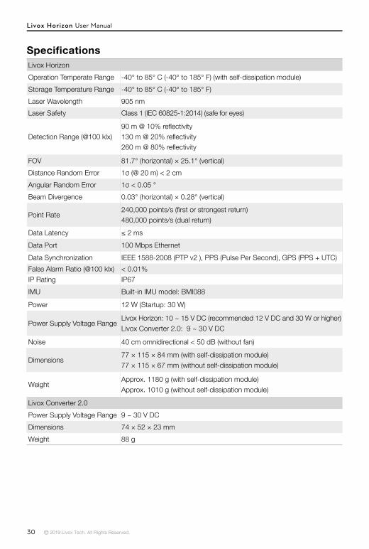
Livox HorizonOperation Temperate Range -40° to 85° C (-40° to 185° F) (with self-dissipation module)Storage Temperature Range -40° to 85° C (-40° to 185° F)Laser Wavelength 905 nmLaser Safety Class 1 (IEC 60825-1:2014) (safe for eyes)
Detection Range (@100 klx)90 m @ 10% reflectivity130 m @ 20% reflectivity260 m @ 80% reflectivity
FOV 81.7° (horizontal) × 25.1° (vertical)Distance Random Error 1σ (@ 20 m) < 2 cmAngular Random Error 1σ < 0.05 °Beam Divergence 0.03° (horizontal) × 0.28° (vertical)
Point Rate240,000 points/s (first or strongest return)480,000 points/s (dual return)
Data Latency ≤ 2 msData Port 100 Mbps EthernetData Synchronization IEEE 1588-2008 (PTP v2 ), PPS (Pulse Per Second), GPS (PPS + UTC)False Alarm Ratio (@100 klx) < 0.01%IP Rating IP67 IMU Built-in IMU model: BMI088
Power 12 W (Startup: 30 W)
Power Supply Voltage RangeLivox Horizon: 10 ~ 15 V DC (recommended 12 V DC and 30 W or higher)Livox Converter 2.0: 9 ~ 30 V DC
Noise 40 cm omnidirectional < 50 dB (without fan)
Dimensions77 × 115 × 84 mm (with self-dissipation module)77 × 115 × 67 mm (without self-dissipation module)
WeightApprox. 1180 g (with self-dissipation module)Approx. 1010 g (without self-dissipation module)
Livox Converter 2.0 Power Supply Voltage Range 9 ~ 30 V DCDimensions 74 × 52 × 23 mmWeight 88 g
Specifications

Copyright © 2019 Livox Tech. All Rights Reserved.Livox and Livox Mid are trademarks of Livox Technology Company Limited.Windows is a registered trademark of Microsoft Corporation in United States and other countries.