little david microjet ac - loveshaw · little david ® microjet ac ™ ink jet coders by ......
TRANSCRIPT
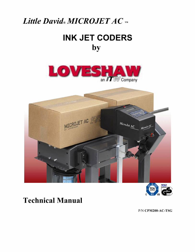
Little David® MICROJET AC ™
INK JET CODERS by
Technical Manual
P/N CPM200-AC-TSG

Loveshaw, an ITW Company Loveshaw Products Division 2206 Easton Turnpike, PO. Box 83 South Canaan, PA 18459 Tel: 1-800-962-2633 • 570-937-4921 Fax: 570-937-4016 www.Loveshaw.com [email protected] Loveshaw Europe A Division of ITW LTD. Unit 9 Brunel Gate West Portway Industrial Estate Andover, Hampshire SP10 3SL ENGLAND Tel: 264-357511 Fax: 264-355964 www.LOVESHAW.com [email protected]
Revised June 28, 2005. Copyright © 2003-2005 Loveshaw. All rights reserved worldwide.
CPM200-AC-TSG.doc 06/28/05 2

TABLE OF CONTENTS Introduction . . . . . . . 4 Unit Overview . . . . . . . 5 PC Communication Installation . . . . 6 Maintenance . . . . . . . 9 General Maintenance . . . . . 36 Fuse Change . . . . . . 14 EPROM Replacement . . . . 15 Battery Replacement . . . . . 15 Printhead Replacement . . . . 16 AC CPU Board CPMA32-003 . . . . 17 AC Driver Board CPMA32-001 . . . . 21 Diagnostic LEDs . . . . . 24 AC Power Supply Board CPMA32-002 . . . 25 AC Power Board Module Assembly CPMA75-230 . . 27 Power Harness Assembly 4 Pin MJ AC CPMA75-232 . 28 Reservoir Assembly Complete CPMA75-229 . . 29 Photocell Assembly CPMA75-212 . . . . 30 AC Quick Initial Start-Up Procedure . . . 31
CPM200-AC-TSG.doc 06/28/05 3

Introduction The MICROJET AC is a low cost, large character ink jet coder using a high resolution Alpha Coder printhead. They are totally enclosed and completely self-contained. Measuring only 13” x 6” x 6”and have been designed for easy installation on any standard conveyor line, minimal maintenance and maximum flexibility.
Standard features include: 5x5, 7x5, and 11x6 dot matrix print. All units include bold double dotting at speeds up to 200 feet per minute. Automatic date and time coding, day of the week designation, Julian dating, alpha/numeric incrementing, automatic box counting, lockout capability and complete keyboard are also included. Keys are also provided for print control
of dot size, product delay and automatic character width. Both are user friendly in every way. Its small size and sophisticated capabilities combine with extraordinary ease of installation, maintenance and operation, for the ultimate in satisfaction – at low cost. Made of sturdy steel, the MICROJET AC is also available in stainless steel.
Personal Protection Equipment: Safety glasses and latex gloves are recommended when using ink jet printers.
CPM200-AC-TSG.doc 06/28/05 4

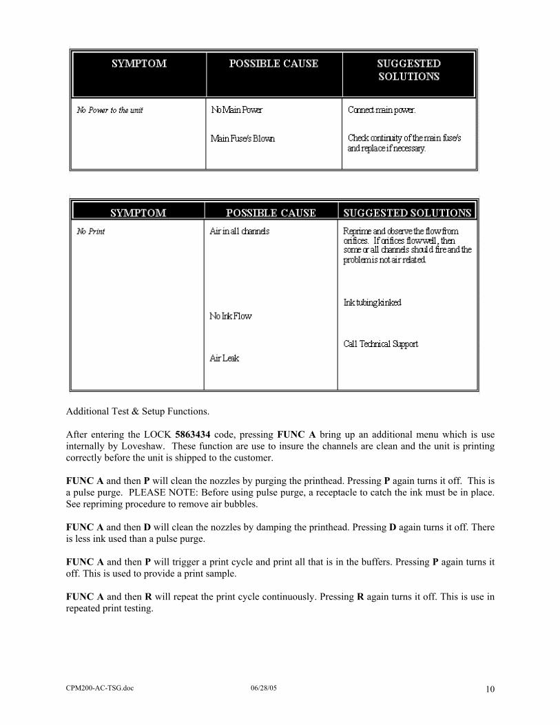
Unit Overview
CPM200-AC-TSG.doc 06/28/05 5

PC Communication Installation (Optional) Communications Port is custom ordered item. Default setup is RS232. RS232 connection is a point-to-point connection where only one COM port may be connected to one MICROJET AC. Using USB RS232 adaptors up to 256 COM ports can be made available. A maximum cable length is typically 50 feet. A maximum cable length is 300 feet using Braided Shielded Extended Quite Cable.
The most common problem occurs because the cable pins 2 and 3 are reversed or the ground wire is not connected. Some RS232 boards have different pin-outs, review hardware supplier provided documentation. The MICROJET AC by default is set to RS232 communications when specially ordered.
CPM200-AC-TSG.doc 06/28/05 6
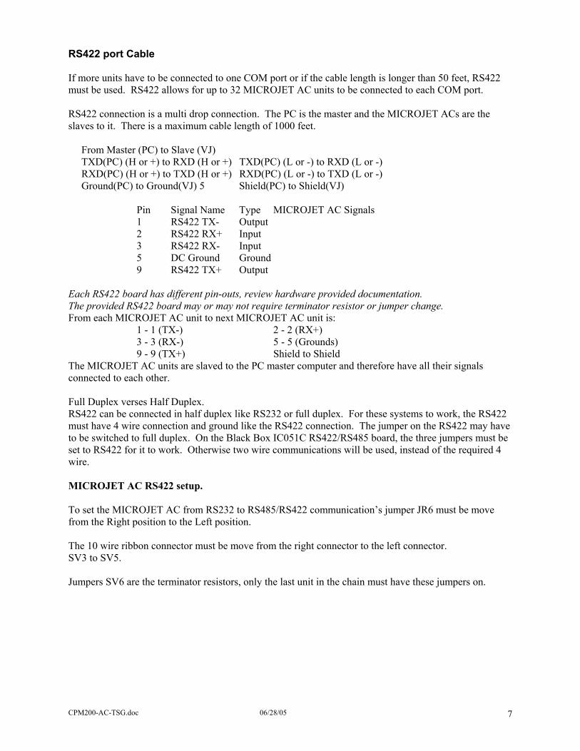
RS422 port Cable If more units have to be connected to one COM port or if the cable length is longer than 50 feet, RS422 must be used. RS422 allows for up to 32 MICROJET AC units to be connected to each COM port. RS422 connection is a multi drop connection. The PC is the master and the MICROJET ACs are the slaves to it. There is a maximum cable length of 1000 feet. From Master (PC) to Slave (VJ) TXD(PC) (H or +) to RXD (H or +) TXD(PC) (L or -) to RXD (L or -) RXD(PC) (H or +) to TXD (H or +) RXD(PC) (L or -) to TXD (L or -) Ground(PC) to Ground(VJ) 5 Shield(PC) to Shield(VJ) Pin Signal Name Type MICROJET AC Signals 1 RS422 TX- Output 2 RS422 RX+ Input 3 RS422 RX- Input 5 DC Ground Ground 9 RS422 TX+ Output Each RS422 board has different pin-outs, review hardware provided documentation. The provided RS422 board may or may not require terminator resistor or jumper change. From each MICROJET AC unit to next MICROJET AC unit is: 1 - 1 (TX-) 2 - 2 (RX+) 3 - 3 (RX-) 5 - 5 (Grounds) 9 - 9 (TX+) Shield to Shield The MICROJET AC units are slaved to the PC master computer and therefore have all their signals connected to each other. Full Duplex verses Half Duplex. RS422 can be connected in half duplex like RS232 or full duplex. For these systems to work, the RS422 must have 4 wire connection and ground like the RS422 connection. The jumper on the RS422 may have to be switched to full duplex. On the Black Box IC051C RS422/RS485 board, the three jumpers must be set to RS422 for it to work. Otherwise two wire communications will be used, instead of the required 4 wire. MICROJET AC RS422 setup. To set the MICROJET AC from RS232 to RS485/RS422 communication’s jumper JR6 must be move from the Right position to the Left position. The 10 wire ribbon connector must be move from the right connector to the left connector. SV3 to SV5. Jumpers SV6 are the terminator resistors, only the last unit in the chain must have these jumpers on.
CPM200-AC-TSG.doc 06/28/05 7
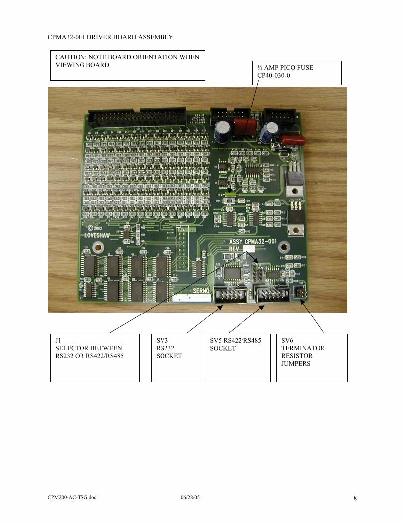
CPMA32-001 DRIVER BOARD ASSEMBLY
CAUTION: NOTE BOARD ORIENTATION WHEN VIEWING BOARD ½ AMP PICO FUSE
CP40-030-0
SV5 RS422/RS485 SOCKET
SV3 RS232 SOCKET
J1 SELECTOR BETWEEN RS232 OR RS422/RS485
SV6 TERMINATOR RESISTOR JUMPERS
CPM200-AC-TSG.doc 06/28/05 8
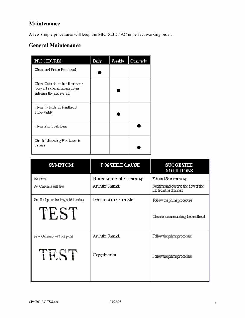
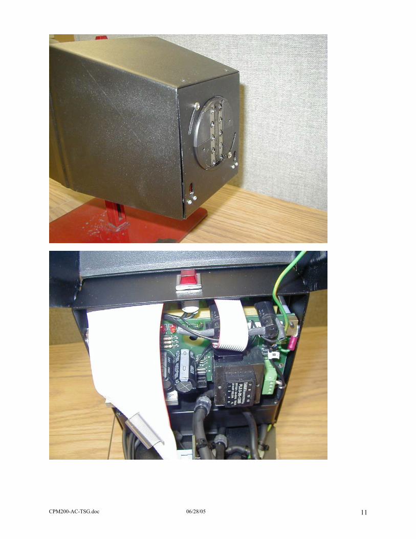
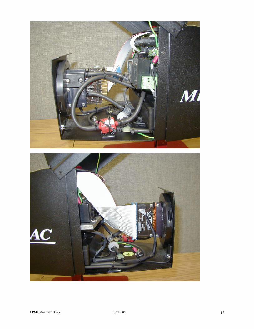
Maintenance A few simple procedures will keep the MICROJET AC in perfect working order. General Maintenance
CPM200-AC-TSG.doc 06/28/05 9
Additional Test & Setup Functions. After entering the LOCK 5863434 code, pressing FUNC A bring up an additional menu which is use internally by Loveshaw. These function are use to insure the channels are clean and the unit is printing correctly before the unit is shipped to the customer. FUNC A and then P will clean the nozzles by purging the printhead. Pressing P again turns it off. This is a pulse purge. PLEASE NOTE: Before using pulse purge, a receptacle to catch the ink must be in place. See repriming procedure to remove air bubbles. FUNC A and then D will clean the nozzles by damping the printhead. Pressing D again turns it off. There is less ink used than a pulse purge. FUNC A and then P will trigger a print cycle and print all that is in the buffers. Pressing P again turns it off. This is used to provide a print sample. FUNC A and then R will repeat the print cycle continuously. Pressing R again turns it off. This is use in repeated print testing.
CPM200-AC-TSG.doc 06/28/05 10
CPM200-AC-TSG.doc 06/28/05 11
CPM200-AC-TSG.doc 06/28/05 12

CPM200-AC-TSG.doc 06/28/05 13
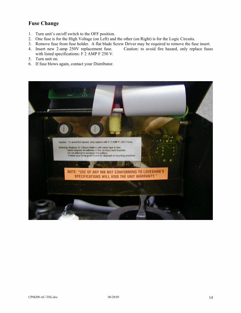
Fuse Change 1. Turn unit’s on/off switch to the OFF position. 2. One fuse is for the High Voltage (on Left) and the other (on Right) is for the Logic Circuits. 3. Remove fuse from fuse holder. A flat blade Screw Driver may be required to remove the fuse insert. 4. Insert new 2-amp 250V replacement fuse. Caution: to avoid fire hazard, only replace fuses
with listed specifications: F 2 AMP F 250 V. 5. Turn unit on. 6. If fuse blows again, contact your Distributor.
CPM200-AC-TSG.doc 06/28/05 14

EPROM Replacement The EPROM is located at U9 on the CPU board in the lid compartment. First the plastic cover must be removed by unscrewing the two 6-32 Phillip screws and long M3 screw. Flip the piggyback board over. This will allow the CPU board to be viewed. The EPROM is in the upper left hand corner, up side down to the viewer. Make sure pin 1 and all pins are in the correct socket, note where the notch is. (The picture below is the board facing the opposite direction.) Battery Replacement Like the EPROM replacement, the battery is on the CPU board in the lid compartment. First the plastic cover must be removed by unscrewing the two 6-32 Phillip screws and long M3 screw. Flip the piggyback board over. This will allow the CPU board to be viewed. The Battery is located in the lower right hand corner. Make sure the plus side is facing up. LITHIUM BATTERY WARNING CAUTION! This product contains a lithium battery. There is danger of explosion if battery is incorrectly replaced. Replace only with a Duracell DL2430 or equivalent. Make sure the battery is installed with the correct polarity. Discard used batteries according to manufacturer's instructions. ADVARSEL! Lithiumbatteri - Eksplosjonsfare. Ved utskifting benyttes kun batteri som anbefalt (Duracell DL2430) av apparatfabrikanten. Brukt batteri returneres apparatleverandøren. ADVARSEL! Lithiumbatteri - Eksplosjonsfare ved fejlagtig håndtering. Udskiftning må kun ske med batteri av samme fabrik(Duracell DL2430) at og type. Levér det brugte batteri tilbage til leverandøren. VAROITUS! Paristo voi räfähtää, jos se on virheellisesti asennettu. Vaihda paristo ainoastaan laitevalmistajan suosittelemaan tyyppin (Duracell DL2430). Hävitä käytetty paristovalmistajan ohjeiden mukaisesti. VARNING! Explosionsfar vid felaktigt batteribyte. Använd samma batterityp eller en ekvivalent typ (Duracell DL2430) som rekommenderas av apparattillverkaren. Kassera använt batteri enligt fabrikantens instruktion. ATTENTION! Il y a danger d’explsion s’il y a remplacement incorrect de la batterie. Remplacer uniquement avec une batterie du même type (Duracell DL2430) ou d’un type équivalent recommandè par le constructeur. Mettre au rebut les batteries usagées conformèment aux instructions du fabricant.
CPM200-AC-TSG.doc 06/28/05 15

Printhead Replacement
CPM200-AC-TSG.doc 06/28/05 16
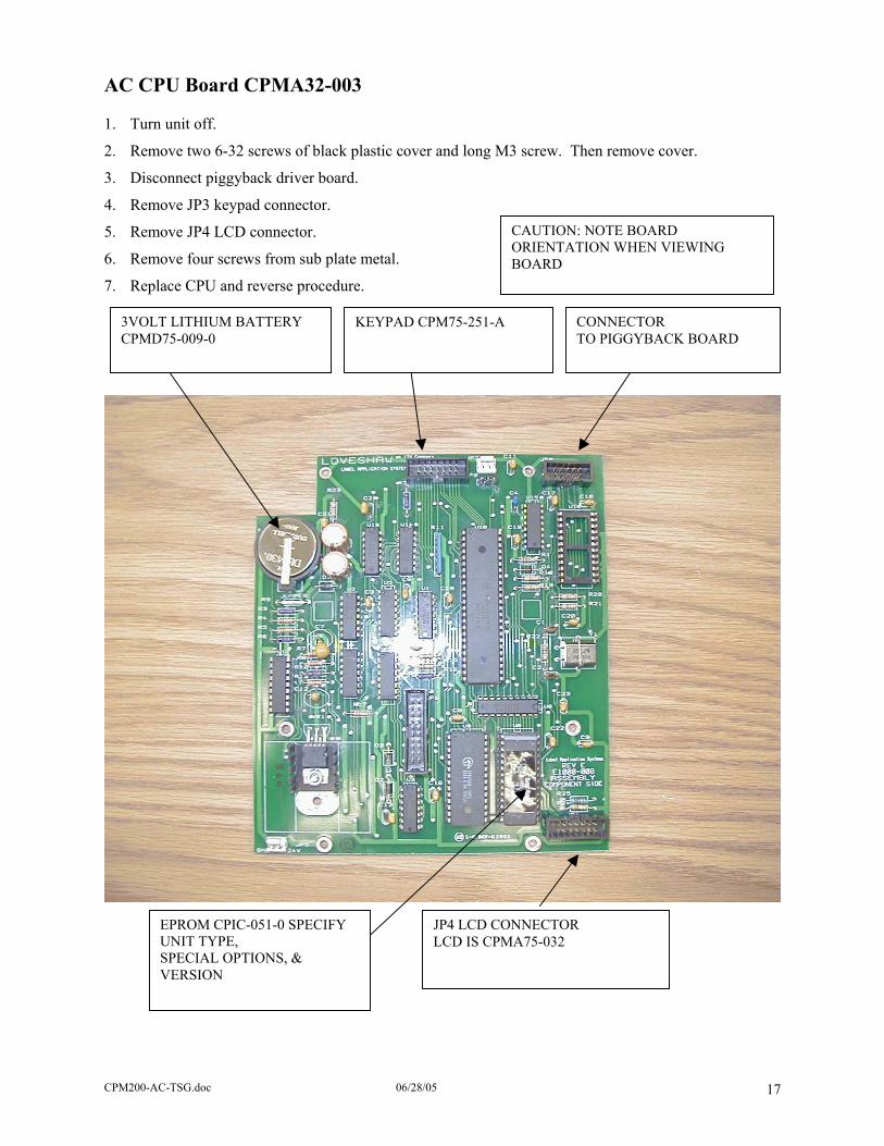
AC CPU Board CPMA32-003 1. Turn unit off.
2. Remove two 6-32 screws of black plastic cover and long M3 screw. Then remove cover.
3. Disconnect piggyback driver board.
4. Remove JP3 keypad connector. CAUTION: NOTE BOARD ORIENTATION WHEN VIEWING BOARD
5. Remove JP4 LCD connector.
6. Remove four screws from sub plate metal.
7. Replace CPU and reverse procedure.
3VOLT LITHIUM BATTERY CPMD75-009-0
KEYPAD CPM75-251-A CONNECTOR TO PIGGYBACK BOARD
JP4 LCD CONNECTOR LCD IS CPMA75-032
EPROM CPIC-051-0 SPECIFY UNIT TYPE, SPECIAL OPTIONS, & VERSION
CPM200-AC-TSG.doc 06/28/05 17

Copyright Loveshaw 2002-2004, All Rights Reserved. CPU Board CPMA32-003
CPM200-AC-TSG.doc 06/28/05 18

Copyright Loveshaw 2002-2004, All Rights Reserved.
CPM200-AC-TSG.doc 06/28/05 19
Copyright Loveshaw 2002-2004, All Rights Reserved.
CPM200-AC-TSG.doc 06/28/05 20
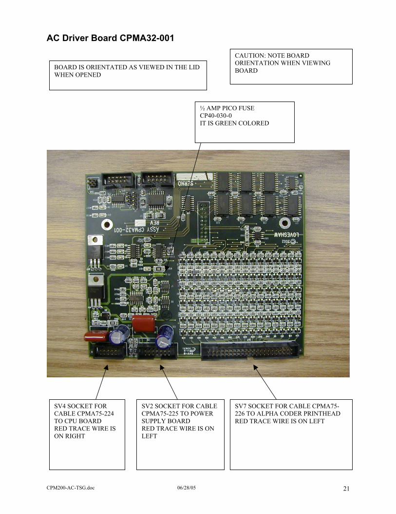
AC Driver Board CPMA32-001
CAUTION: NOTE BOARD ORIENTATION WHEN VIEWING BOARD
BOARD IS ORIENTATED AS VIEWED IN THE LID WHEN OPENED
½ AMP PICO FUSE CP40-030-0 IT IS GREEN COLORED
SV4 SOCKET FOR CABLE CPMA75-224 TO CPU BOARD RED TRACE WIRE IS ON RIGHT
SV2 SOCKET FOR CABLE CPMA75-225 TO POWER SUPPLY BOARD RED TRACE WIRE IS ON LEFT
SV7 SOCKET FOR CABLE CPMA75-226 TO ALPHA CODER PRINTHEAD RED TRACE WIRE IS ON LEFT
CPM200-AC-TSG.doc 06/28/05 21

F1 – ½ Amp Pico Fuse
Copyright Loveshaw 2002-2004, All Rights Reserved.
CPM200-AC-TSG.doc 06/28/05 22
Copyright Loveshaw 2002-2004, All Rights Reserved.
CPM200-AC-TSG.doc 06/28/05 23

Diagnostic LEDs
THIS IS VIEW WHEN LID IS OPEN AND BOARD IS IN LID COMPARTMENT.
D9 D10
D6 D7 D4 D5 D11 D3
D3 Heater Voltage On CAUTION: NOTE BOARD
ORIENTATION WHEN VIEWING BOARD
D4 Heater On Signal D5 Low Ink D6 Printhead AT Temperature D7 Printhead High Voltage OK D9 +12VDC D10 +5VDC D11 +150VDC
CPM200-AC-TSG.doc 06/28/05 24

Power Supply Board CPMA32-002 CAUTION: NOTE BOARD ORIENTATION WHEN VIEWING BOARD
Fuse F1 High Voltage Input Power
Photocell 1Photocell 2
Fuse F2 Circuit Power
Power to Piggyback Board
Two Spare Photocell Connectors
Relay Connection 1 +24VDC 2 NC 3 Common 4 NO 5 Ground
LED Indicators D3 +24VDC D4 +12VDC D5 +150VDC
CPM200-AC-TSG.doc 06/28/05 25

AC Power Board CPMA32-002
Copyright Loveshaw 2002-2004, All Rights Reserved.
CPM200-AC-TSG.doc 06/28/05 26
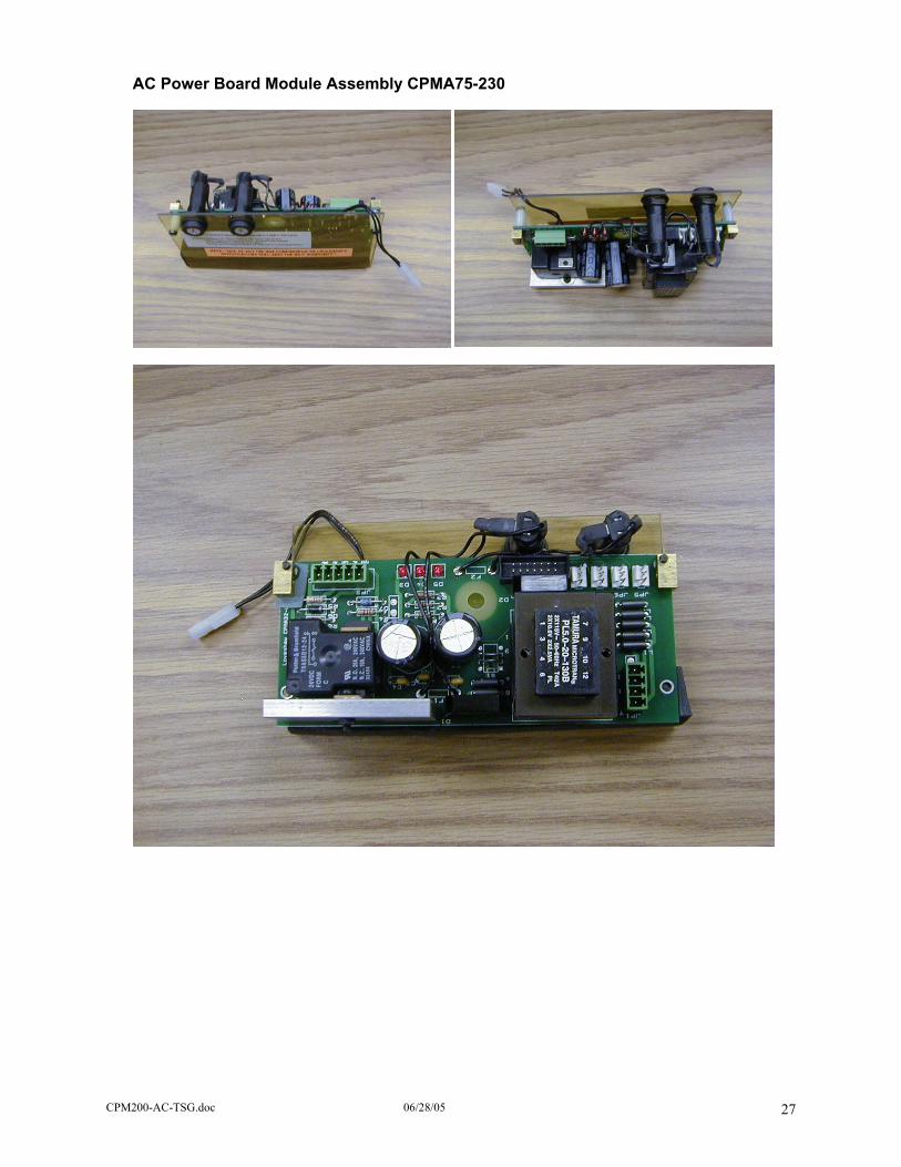
AC Power Board Module Assembly CPMA75-230
CPM200-AC-TSG.doc 06/28/05 27
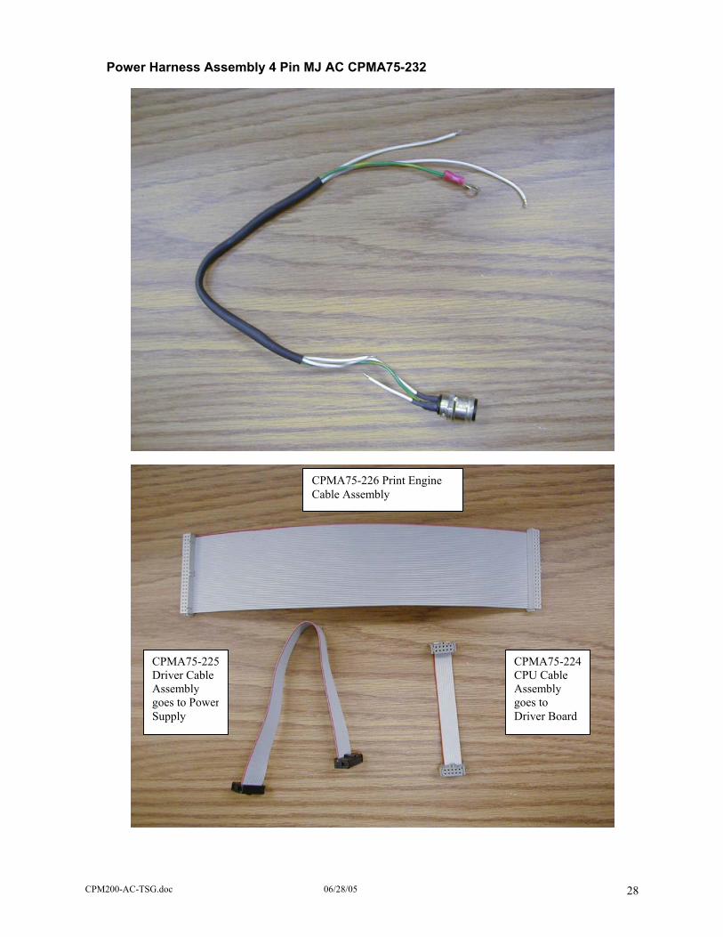
Power Harness Assembly 4 Pin MJ AC CPMA75-232
Board
CPMA75-226 Print Engine Cable Assembly
CPMA75-225Driver Cable Assembly goes to PowerSupply
CPMA75-224CPU Cable Assembly goes to Driver
CPM200-AC-TSG.doc 06/28/05 28
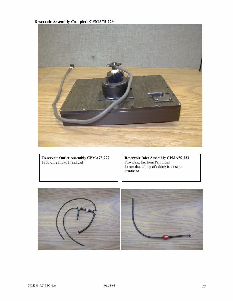
Reservoir Assembly Complete CPMA75-229
Reservoir Outlet Assembly CPMA75-222 Providing Ink to Printhead
Reservoir Inlet Assembly CPMA75-223 Providing Ink from Printhead Insure that a loop of tubing is close to Printhead
CPM200-AC-TSG.doc 06/28/05 29
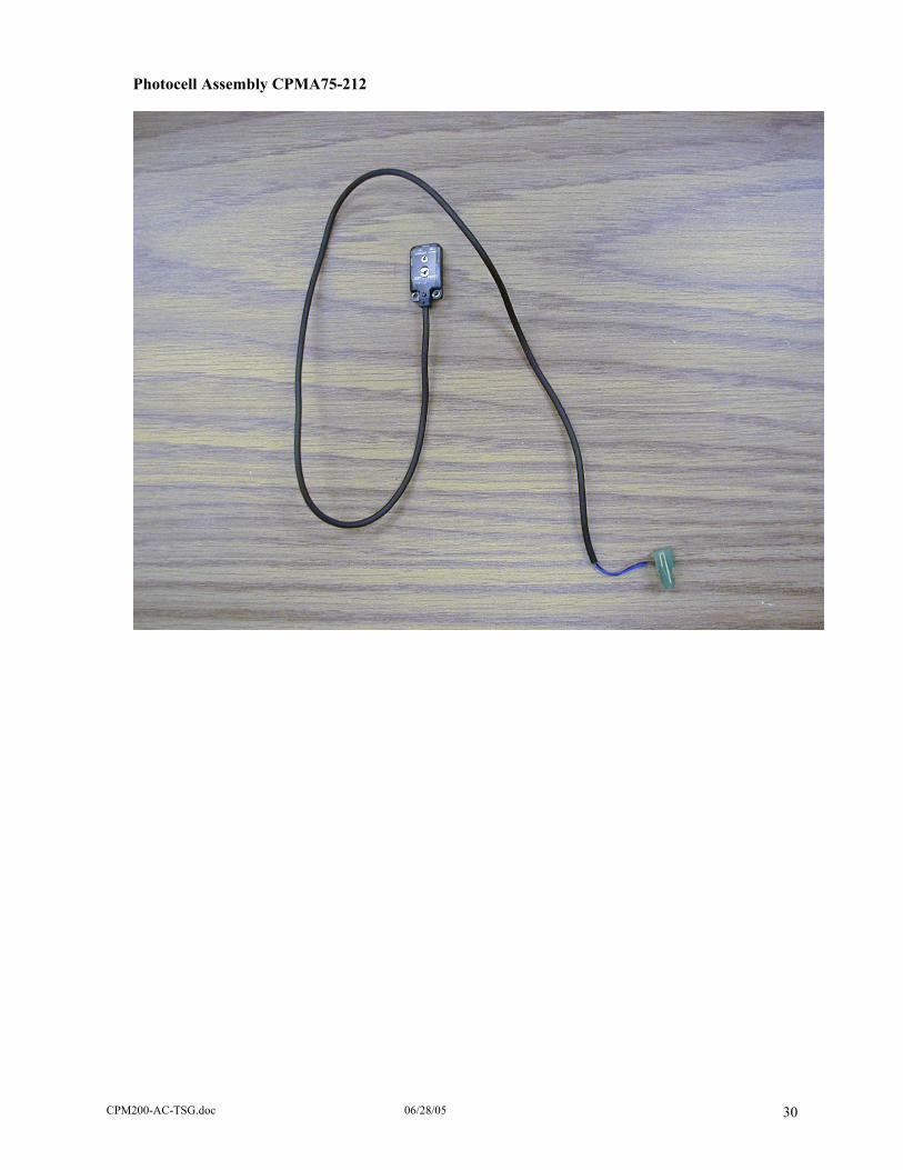
Photocell Assembly CPMA75-212
CPM200-AC-TSG.doc 06/28/05 30

CPM200-AC-TSG.doc 06/28/05 31
MicroJet AC Quick Initial Start-Up Procedure (Follow Completely)
1. Remove MicroJet AC, Transformer, Mounting Block and L-Bracket from shipping box.
2. Bolt Mounting Block Assembly to desired location.
3. Slide L-Bracket into block and lock into position with Hand Knob of Mounting Block.
4. Loosen two wing nuts of Clamping Nut and slide MicroJet AC onto L-Bracket.
5. After MicroJet AC is secured on L-Bracket, system must be level on length and width of unit.
6. Plug secondary line of Transformer to MicroJet AC.
7. Align keyway of four-pin connector to mating connector on bottom corner of unit and tighten.
8. Plug primary line of Transformer into AC outlet.
9. A dedicated AC line or line conditioner is recommended.
10. Lift open rear panel until locked in position.
11. Open vent cap. Note: vent cap must remain open for normal operation.
12. Unscrew Ink Reservoir Cap and set aside on clean dust-free surface.
13. Open AlphaMark Ink bottle by removing plastic seal. Insure all of plastic seal is removed.
14. Align bottle to Ink Reservoir fill opening, invert and firmly screw into Ink Reservoir fill opening.
15. Allow several minutes for bottle to empty into reservoir.
16. After Reservoir is filled, remove AlphaMark Ink bottle and replace Ink Reservoir Cap.
17. Close rear cover by depressing spring plunger on side of unit and gently close rear cover.
18. Push power switch on rear panel to the “on” position.
19. Low Ink Lamp must be off. If Lamp is on, repeat ink fill section of procedure.
20. To unlock MicroJet AC, type in 5 8 6 3 4 3 4.
21. First time start-up requires priming of system.
22. Allow print engine of MicroJet AC to heat to proper temperature. Average time is ten minutes.
23. Press MENU D 5 to view the print engine temperature; @temp:0 not to temp @temp:1 to temp.
24. Leave this MENU function on to keep unit from printing.
25. Push (do not squeeze or pinch) Priming Bulb in firmly, release until bulb to returns to dome state.
26. Repeat prime for four to five times to prime system. Ink recycles back to Ink Reservoir.
27. Remove Ship Cap from front of unit by removing two screws.
28. Save Ship Cap and screws in safe location. Replace Ship Cap if shipping or storing unit.
29. While pushing Priming Bulb lightly, gently wipe faceplate of print engine with lint free cloth.
30. Repeat until air is removed from system.
31. Align unit perpendicular to product.
32. Press EDIT key, type in desired message then ENTER. 33. Print.