literature review and problem statement - bu.edu.eg · pdf filethe fifth category is the...
TRANSCRIPT

1
1 Literature Review and Problem Statement
Chapter (1)
Literature Review and Problem Statement
1.1 Introduction
In recent years, electrohydraulic systems have been widely used in modern industries because of
their durability, high power to weight ratio, controllability, accuracy and reliability. The
electrohydraulic systems are often employed in high performance applications. These applications
include the control of active suspension systems [1,2], power steering systems [3], material testing
systems[4], camless engines [5], earth moving industries [6], load simulators [7], the control of
multi-axis robotic manipulators [8].
The hydraulic system composed of six basic components, a tank (reservoir) to carry the hydraulic
oil, a pump to force the oil through the system with a certain flow rate, an electric motor or other
power source to drive the pump with a suitable torque, valves to control oil direction, pressure, and
flow rate, an actuator to convert the pressure of the oil into mechanical force or torque to do
a useful work (they are in the form of cylinders or motors), and a piping system, or transmission
lines, which carry the oil from one location to another. They can be summarized as shown in
Fig. 1.1.
Fig. 1.1 The functional block diagram of hydraulic power systems
The hydraulic actuator, usually a cylinder, converts the hydraulic power to mechanical power
appears in the motion of the load attached to the hydraulic system. The control valves either meters
the fluid into the actuator as a spool traverses within the valve body (i.e. flow control), or changing
the direction of oil flow (i.e. direction control), or make an action according to the increase (or
decrease) of the system pressure (i.e. pressure control).

2
1 Literature Review and Problem Statement
There are five categories of control according to [9]. The first category is the most common
solenoid valve (i.e. on/off valve). Each has a simple built-in electrical solenoid-and-armature
actuator, to open and close the valve passage. Flow and subsequent pressure build-up are well
defined by the size and nature of the valve and other circuit elements, but the valve does not have
variable flow.
The second category is the proportional solenoid valve (i.e. proportional valve). Basically, its valve
spool position is made to vary directly in response to electrical current fed to the solenoid that
drives it. Some designs are complex and can adjust either flow or pressure under close control of
the input electrical signal. A sophisticated proportional valve can behave in many ways like a
servo valve.
The third category is the servo valve. It designed primarily for feedback control. It predates
proportional solenoid valves and usually is based on controlling the position of the main valve
spool with pilot valves. The pilot valves are moved with electrical force motors or torque motors
that respond precisely to low-power electrical input signals.
The fourth category is the rapid on-off solenoid valve (i.e. fast switching valve). It modulates flow
by rapidly opening and closing the valve passage, alternately passing and blocking flow. The
variation in length of on-time vs. off-time establishes an average flow (or pressure build-up) of any
amount desired. Some engineers prefer the term "pulse-width-modulated (PWM) valve" instead of
"rapid on-off valve" because the operation parallels, in principle, the pulse-width modulation of
high-speed, solenoid-state electronic switches, but at a much slower cycling rate.
The fifth category is the stepmotor-modulated valve wherein a microprocessor control sends
discrete signal pulses to a stepmotor, which in turn positions the pilot or spool.
The most common two types of control valves used for accurate continuous control purposes are
the proportional valve and the servo valve. Table 1.1 demonstrates some of the basic differences
between them.
3
1 Literature Review and Problem Statement
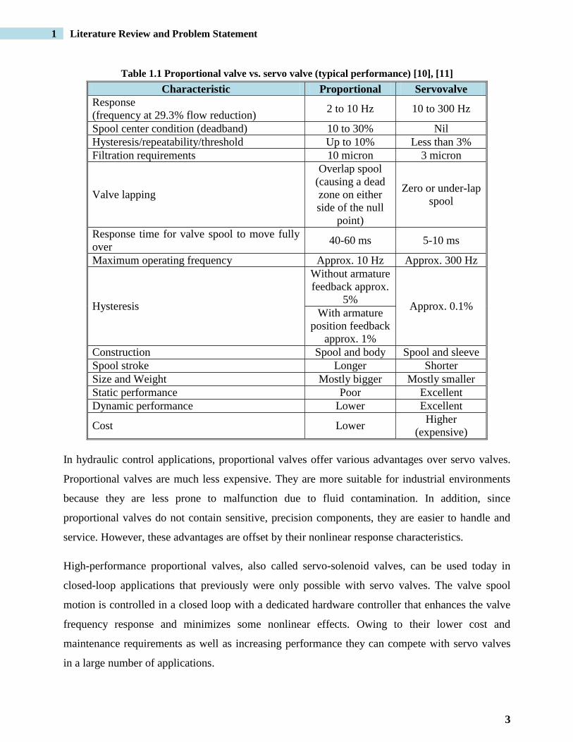
Table 1.1 Proportional valve vs. servo valve (typical performance) [10], [11]
Characteristic Proportional Servovalve
Response
(frequency at 29.3% flow reduction) 2 to 10 Hz 10 to 300 Hz
Spool center condition (deadband) 10 to 30% Nil
Hysteresis/repeatability/threshold Up to 10% Less than 3%
Filtration requirements 10 micron 3 micron
Valve lapping
Overlap spool
(causing a dead
zone on either
side of the null
point)
Zero or under-lap
spool
Response time for valve spool to move fully
over 40-60 ms 5-10 ms
Maximum operating frequency Approx. 10 Hz Approx. 300 Hz
Hysteresis
Without armature
feedback approx.
5% Approx. 0.1%
With armature
position feedback
approx. 1%
Construction Spool and body Spool and sleeve
Spool stroke Longer Shorter
Size and Weight Mostly bigger Mostly smaller
Static performance Poor Excellent
Dynamic performance Lower Excellent
Cost Lower Higher
(expensive)
In hydraulic control applications, proportional valves offer various advantages over servo valves.
Proportional valves are much less expensive. They are more suitable for industrial environments
because they are less prone to malfunction due to fluid contamination. In addition, since
proportional valves do not contain sensitive, precision components, they are easier to handle and
service. However, these advantages are offset by their nonlinear response characteristics.
High-performance proportional valves, also called servo-solenoid valves, can be used today in
closed-loop applications that previously were only possible with servo valves. The valve spool
motion is controlled in a closed loop with a dedicated hardware controller that enhances the valve
frequency response and minimizes some nonlinear effects. Owing to their lower cost and
maintenance requirements as well as increasing performance they can compete with servo valves
in a large number of applications.

4
1 Literature Review and Problem Statement
1.2 Literature Review
The literatures survey can be organized as follows:
- Survey about works related to different types of control valves,
- Survey about works related to valve actuators,
- Survey about works related to modeling and identification of hydraulic systems,
- Survey about works related to the main problems of control valves (nonlinearities),
- Survey about works related to the applications of different controllers for electrohydraulic
servo systems, and
- Survey about cerebellar model articulation controller and its applications.
1.2.1 Works related to different types of control valves
In this part of the review, the works related to the performance enhancement for different control
valves types are introduced. The literatures used in this part are summarized in sections according
to the control valve type.
1.2.1.1 On/off solenoid valves
The following researches deal with the on/off solenoid valves. Malaguti and Pregnolato [12]
investigated about continuous and proportional control of on/off solenoid driving spool directly by
nonlinear control using variable structure control VSC and using solenoid model to estimate spool
position. Magnetic model of solenoid and hydraulic flow forces of valve were carried out without
to use FEM techniques. The spool position was estimated without a sensor by using the derivative
of current method.
Ahn and Yokota [13] presented a modified pulse-width modulation (MPWM) valve pulsing
algorithm allows on/off solenoid valves to be used in place of costly servo valves. A state-
feedback controller with position, velocity and acceleration feedback was successfully
implemented as a continuous controller. A switching algorithm for control parameters using a
learning vector quantization neural network (LVQNN) has newly proposed, which classifies the
external load of the pneumatic actuator.
Gentile et al. [14] presented a position-controlled pneumatic actuator using pulse width modulation
(PWM) valve pulsing algorithms. A proportional integrative (PI) controller with position

5
1 Literature Review and Problem Statement
feedforward is successfully implemented. Experimental tests under a variety of conditions such as
system mass, input type (step, multisteps or ramp) and flow control settings (on and wide open)
were applied. The result was a fast, accurate and inexpensive position-controlled pneumatic
actuator that may he applied to a variety of practical positioning applications.
Tao et al. [15] presented an optimal design method on the HSV‟s (high-speed response solenoid
valve) magnetic field by making a full consideration of the effects of various soft magnetic
material‟s properties and geometries on the HSV‟s electronic performance. They tried to achieve a
larger magnetic force and a lower power of an HSV by adjusting the structural parameters of the
solenoid valve and selecting various soft magnetic materials that are of different B–H (flux density
vs. field intensity) curves.
1.2.1.2 Proportional valves
The following literatures are directed to the work with proportional valves in electrohydraulic
systems and the different control algorithms used for enhancing their performance.
Eryilmaz and Wilson [16] developed a unified model for proportional control valves and analyzed
the effect of spool lapping on open-loop hydraulic system properties. The developed nonlinear
equations were used to obtain simplified flow rate expressions under generally accepted
assumptions. These unified model equations are useful for simulation and nonlinear controller
design.
Renn and Tsai [17] built an electro-hydraulic proportional flow control valve with lowest cost by
developing a proportional switching solenoid. The fuzzy-logic controller was used to linearize the
force/stroke characteristics of the normal switching solenoid valve.
Hamdan and Gao [18] developed a Modified PID (MPID) controller to control and minimize the
effect of hysteresis in Pneumatic proportional valves. It consists of four parts: a Proportional-
Integral-Derivative (PID) controller, a Feedforward term, an Anti-Windup mechanism, and a
Bang-Bang controller. The result is a unique Modified PID (MPID) control scheme that
demonstrates better command following and disturbance rejection qualities than a conventional
PID (PID + Feedforward + Anti-windup) scheme, and also provides better step response,

6
1 Literature Review and Problem Statement
command following, robust control in the presence of significant dynamic variations in the valve,
and greater bandwidth than conventional methods.
Kiković [19] developed a mathematical model of filling chamber controlled with proportional
spool valve. Use different geometry of valve output port; the aim was defining optional geometry
so that pressure response in chamber is sufficiently linear and quick. Valve dynamics, the
nonlinearity of the valve effective area with respect to the coil current, and the nonlinear turbulent
flow through the valve orifice were also considered. The other construction aspects of proportional
valve were analyzed. For example, the spool spring constant has huge influence on time of
pressure response and it is possible to have this time less than 1 sec what is demand for
hydrodynamic brake.
Dobchuk [20] developed a model reference control scheme to provide control of the valve spool
displacement for a particular electrohydraulic proportional valve. He presented the conditions by
which the linearizing feedforward controller produces excellent velocity tracking characteristics
and concluded that the linearizing feedforward approach has the potential for excellent response,
disturbance rejection and repeatability when used as a single component pressure compensated
flow control device.
Ferreira et al. [21] described a new semi-empirical modeling approach for hydraulic proportional
spool valves to be used in hardware-in-the-loop simulation experiments. The model described the
behavior of the whole hydraulic valve package (valve, spool position transducer and electronic
controller card). Spool dynamics are modeled by a non-linear second-order system, with limited
velocity and acceleration, the parameters being adjusted using optimization techniques. The
developed models use either data sheet or experimental values to fit the model parameters in order
to reproduce both static (pressure gain, leakage flow rate and flow gain) and dynamic (frequency
response) valve characteristics. The model accurately reproduces the amplitude Bode diagram up
to 200 Hz. The phase response still has room for improvement, mainly at high frequencies.
Lee et al. [22] introduced a tracking position controller (type PID) for a pneumatic actuator and
evaluated it experimentally. The positioning system is composed of a pneumatic actuator and a 5-
port proportional valve. The experimental results indicate that the tracking performance can be
significantly improved with the proposed controller. If the model of dynamic nonlinearities such as

7
1 Literature Review and Problem Statement
friction and compliance are identified and incorporated into the feedback linearization, and if the
noise coming from differentiating position is minimized by directly measuring the velocity, further
improvement of tracking accuracy may be achieved.
1.2.1.3 Servo valves
Yuan and Lew [23] presented a nonlinear model and a control strategy of two stage twin spool
servo valves in the load-sensing mobile applications were developed featuring energy saving. The
multiple sliding surface mode control method was then utilized to accomplish the motion control
while regulating back pressure. The simulation verifies that the proposed control scheme for the
twin spool valve, can offer the more significant energy-saving even with load-sensing pump
application than the traditional proportional valves.
Wang et al. [24] presented a nonlinear dynamic model for a 4-port servo valve with dual fixed
orifices and dual nozzles. This includes the dynamics of the torque motor, the flow rate
characteristics of the fixed orifices and variable nozzle-flappers, and the flow force on the flapper.
The model was validated by simulation using Matlab/Simulink. A linear model was derived from
the nonlinear model, and is applicable over a range of about ±30% of the rated input current.
1.2.1.4 Fast switching valves
Topçu et al. [25] designed a simple fast switching valve controlled with PWM for applications of
pneumatic position control has been investigated. Four prototype 2/2 on-off valves had been built
and the basic mode of operation confirmed. The theoretical and experimental results have shown
that the opening time of the valves were as fast as 3 ms and the closing time of the valves was 6 ms
under 7*105 N/m2 of supply pressure. PWM controlled valves provide a good linearity up to 33
Hz. It has been demonstrated that the switching speed of the valves can be enhanced by the
application of overdriving current to the coils during the switching action and then by reducing the
applied current to a holding current level after the switching is completed. With this way, the
electrical power required to hold the close after switching is completed can be reduced about 6%
of the peak power and the closing time of the valves can be reduced about 50% of the highest
closing time. The valves developed in this study have a simple construction and provide higher
flow rates (460 l/min) as single stage valves than conventional servo valves and fast switching
valves.

8
1 Literature Review and Problem Statement
Ertl et al. [26] presented a 2D nonlinear magneto-mechanical analysis of an electromagnetic
actuator based on finite elements. The presented method enables the simulation of the complete
switching cycle of fast switching, short stroke solenoid actuators with sufficient accuracy. This
could be achieved by considering nonlinear magnetics, eddy current induction and a physical
correct implementation of the contact mechanics, which are relevant for the complex dynamics of
this valve types. Combining the concepts of pre-magnetization as well as over excitation to
optimize the actuator dynamics, the pure valve needle flight time at valve opening can be reduced
to 200ms. The developed numerical tools enable a systematic study of several methods to optimize
the dynamics.
Pohl et al. [27] presented a model of a fast 2/2 switching valve where both the magnetic path as
well as the spool assembly are modeled. The model also includes a description of the hysteresis
characteristics of the magnetic path. An optimization strategy has been utilized in order to
parameterize the model against measured data. However, even for major deviations from the
operational point used for the model adaptation, the model predicts the valve response sufficiently
accurately. The switching cycle was less than 10 ms.
Zöppig et al. [28] discussed the application of switching valves with electromagnetic actuators for
servopneumatic drives. Fast acting (switching times of 1 ms or less) valves with nominal bores of
1 mm or more (at the industrial pressure of 6 bars) are needed in order to replace expensive 5/3-
way proportional valves. The needed control, power and communication electronics were done by
the use of the modular framework for microsystems "Match-X”. A valve was presented for an
integrated servopneumatic cylinder.
Garstenauer [29] used another principle for a hydraulic switching valve in order to achieve short
switching time and low energy consumption. He used piezoelectric actuator because of its
properties like very high dynamics, high forces and small displacement. A combined simulation
model for piezo actuator, beam, and power electronics was developed and showed results for a 1
ms valve. Two prototypes were presented with hydraulic actuation showed 2.5 and 5 ms valves.
Belforte et al. [30] developed and tested a method for coordinating the use of PWM driven digital
valves with different flow rate and response time within pneumatic servosystems. They used a
system that uses couples of valves in parallel; a valve is supposed to be characterized by low size

9
1 Literature Review and Problem Statement
and very short commutation time 10/20 ms, while the other one‟s main characteristics are large
size and long commutation time. The first valve is intended to ensure precision and high command
signal update frequency, while the aim of the second valve is to ensure large flow rate when
necessary. The final result makes it possible to significantly increase the dynamic performance of
pneumatic servo systems with PWM piloted digital valves. The experimentation was carried out on
a sample case of pressure control and it highlighted an increase in the servo system‟s passband,
which approaches 2 Hz compared with values of 0.6–0.9 Hz measured with the high frequency
valve alone.
1.2.2 Works related to valve actuators
The dynamic response, null shift, threshold, and hysteresis are the most critical valve parameters
that strongly influence the dynamic and static characteristics of the hydraulic actuator. These
characteristics are related to the type of the electromechanical valve transducer. The classification
of the electromechanical valve transducers can be summarized according to [31] as shown in
Fig. 1.2.
Fig. 1.2 Electromechanical valve transducers according to the principle of operation
Eyabi and Washington [32] presented the modeling and control of an electromagnetic valve
actuator. The model was nonlinear and took into account secondary nonlinearities like hysteresis,
Piezoelectric
Transducers
Electromechanical
Transducers
Electromagnetic
Transducers
Linear Force Motor
(linear)
Proportional
Solenoid
Solenoid Actuators
(linear)
Torque Motor
(rotary)
On/off (switching)
Solenoid

10
1 Literature Review and Problem Statement
saturation, bounce and mutual inductance. A sliding mode based „„sensorless‟‟ control strategy
was implemented in simulation and experimentally to reduce impact noise and seating velocity.
Karpenko and Sepehri [33] presented a neural network pattern classifier to carry out fault
diagnosis and identification upon the actuator of a Fisher–Rosemount 667 industrial process valve.
Valve deadband, hysteresis, dynamic linearity and dynamic errors were considered. The test results
show that the resulting network has the ability to detect and identify various magnitudes of
incorrect supply pressure, diaphragm leakage, and vent blockage faults.
Yun et al. [34] introduced a pressure regulator which is used for controlling the reducing pressure
in the piezoelectrically driven pneumatic valve. The pneumatic valve of this study object is 2-stage
type and consists of a piezoelectric actuator, a controller, a poppet valve and a pressure regulator.
Nominal flow of 50 1pm, maximum operating pressure of 0.9MPa and frequency characteristic of
1OHz and over are required in this pneumatic valve, the pressure regulator is needed because
piezoelectric actuator has no ability to control the pressure of 0.9MPa directly. The actuator used
was bimorph type PZT actuator with maximum operating force of 0.052 N and maximum
displacement of 63 µm were gotten from the fabricated PZT actuator. It was confirmed that the
performance characteristics of manufactured pressure regulator are superior in the common use
pressure range of 0.5 MPa to 0.7 MPa. The results show that the proposed pressure regulator is
suitable for the pneumatic valve with a PZT actuator.
Wong et al. [35], [36] studied the performance of the poppet valve through investigation of inflow
and outflow for the range of small and controllable openings made available from the employment
of a practical piezo-electric stack driver. CFD package were used to simulate the results. The
results from which are verified experimentally for several outflow, poppet lifts, cone angles, and
pressure drops for the steady, non-isothermal flow of a test liquid. (Tellus R37). unsteady/moving
boundary and transient flow was tackled using a fast and precise piezo stack to actuate the same
poppet head variations (as in the steady state case) as are the effects of manufacturing tolerances
on poppet eccentricity, angular misalignment, and seat chamfering for small displacements.
Li et al. [37] presented a permanent-magnet actuator with bidirectional and high levels of linear
force over short strokes which can be used in high pressure applications like electrohydraulic
valves. Its static and dynamic performances were analyzed by using two-dimensional finite-

11
1 Literature Review and Problem Statement
element magnetic field solutions that take into account the nonlinearity of the material. The
actuator can produce a force of ±60 N, its nonlinearity is less than 0.5 %, and the hysteresis is less
than 2 % within a stroke of ± 1 mm. The actuator has a bandwidth reach 150 Hz.
Bang et al. [38] presented two systems of two-stage electrohydraulic servo valve with a nozzle-
flapper pilot stage, which is controlled by stack-type piezoelectric elements and a displacement-
magnifying mechanism. These systems can compensate for the hysteresis problem and thermal
expansion of the piezoelectric elements. They achieved a frequency response reached to 600 Hz
for the flapper moving mechanism and 300 Hz for the simplified servo valve system at 3 dB
amplitude decrease and 90º phase delay under the supply pressure of 210 bar.
1.2.3 Works related to modeling and identification of hydraulic systems
An important step in designing a control system is the modeling of the plant to be controlled. An
exact plant model should produce output responses similar to those of actual plant. Without a
proper model, accurate nonlinear analysis of hydraulic system performance is not possible. System
identification is a prerequisite to analysis of a dynamic system.
Ziaei and Sepehri [39] analyzed the identification of a typical electrohydraulic positioning system.
They showed that in spite of highly nonlinear behavior of such a system, a third-order discrete-
time linear model was shown to be flexible enough to fit the observations well, and it is suitable
for adaptive control techniques that are based on single-step-ahead predictions such as model
reference controllers.
Yousefi et al. [40] studied the application of differential evolution algorithm to solve the minimal
representation problem in system identification of a servo-hydraulic system with a flexible load.
The results show that the DE algorithm accurately identified the time delay, structure and
parameters of the system with a fast convergence rate. The advantage of the DE algorithm over
conventional system identification methods are its simplicity, speed of calculation, and
convergence, accurate solutions regardless of the initial conditions of parameters.
Ning and Bone [41] presented a methodology for deriving a nonlinear dynamic model for a
pneumatic servo system. The model included cylinder dynamics, payload motion, friction and
valve characteristics. Methods for estimating the model parameters from simple experiments are

12
1 Literature Review and Problem Statement
also described. It is shown that the standard mass flow rate valve model is not well suited to an
open-center proportional valve. Their validation tests demonstrated that the model is quite accurate
when the valve is operating in either the fully filling or fully discharging modes. However, its
performance in the partially filling/discharging region was much less accurate.
Helling et al. [42] presented the development of a Data Acquisition (DAQ) system to be used in
conjunction with fuzzy modeling to derive a dynamic mathematical model of a control valve. The
valve specific physical data, such as temperatures, mass flow rate, pressures and corresponding
valve opening, were included.
Eryilmaz [43] developed detailed nonlinear models of orifice and leakage flows in proportional
and servo valves, and studied the application of singular perturbation control to hydraulic systems.
The valve model provided a concise description of orifice flows for a wide range of proportional
valves with various spool types. The leakage model resulted in a better characterization of leakage
flow within servo valves, especially around null spool position where leakage flow is likely to
dominate. The singular perturbation control ensured robustness against uncertain and time-varying
fluid bulk modulus, an effect present in all hydraulic systems.
1.2.4 Works related to the main problems of control valves (nonlinearities)
Linear systems can be defined by those systems having elements described by linear differential
equations. Some attributes of linear systems are:
1. Because a mathematical theory exists for the solution of these equations, all aspects of
performance, such as stability and response, are predictable.
2. Using the principle of superposition, the system response to several inputs can be obtained
by adding individual responses.
3. They are completely described by transfer functions.
4. Simplicity of analysis.
5. Availability of many design techniques
Thus, the presence of nonlinearities, e.g., hysteresis, stiction or deadband in a control valve limits
the control loop performance.

13
1 Literature Review and Problem Statement
Choudhury et al. [44] introduced a generalized definition and mechanism of valve stiction based
on the investigation of the real plant data and proposed another data-driven empirical model of
stiction. It also validates the simulation results generated using the proposed model with that from
a physical model of the valve. Finally, valuable insights on stiction have been obtained from the
describing function analysis of the newly proposed stiction model.
Choudhury et al. [45] introduced a non-invasive method for detecting and quantifying stiction in
control valve. The method first detects nonlinearity in a control loop by the use of the sensitivity of
the normalized bispectrum or bicoherence to the nonlinear interactions that may be present in the
control error signal. If nonlinearity is detected, filtered process output and controller output signals
were plotted. If an ellipse can be fitted suitably onto their plots, this is an indication of the
signature of valve stiction. Over a dozen industrial case studies have demonstrated the wide
applicability and practicality of this method as a useful diagnostic aid in control loop performance
monitoring.
Yamashita [46] developed a method to detect valve stiction for diagnosis of oscillation based on
observations of control loops. Formalism for the qualitative description of input–output
characteristics of a valve is also proposed for implementation of the detection algorithm. The
proposed index was applied to industrial plant data and can detect all stictions and can also
distinguish stiction from poor controller tuning and external disturbances. Therefore, this index
will be a useful index for monitoring process control loops. It showed excellent performance in
detecting stiction.
The second important nonlinearity is the hysteresis phenomenon. Hysteresis can be defined by the
difference in actuator input currents required to produce the same actuator output as the actuator
slowly cycles between plus and minus rated current. The total hysteresis value has two
components; the first one is the magnetic reversal of the magnetic solenoid parts and the second is
connected with friction force in the mobile parts. The improvement of the hysteresis characteristic
can be achieved using the dither [31], that is, the armature oscillations at high frequency exist to
overcome static friction. In this case, low amplitude (about 10 to 15% from the maximum value of
the control signal), a relatively high-frequency (about 10 to 15 times more than the solenoid‟s
natural frequency) periodic signal is superimposed on the input current signal.

14
1 Literature Review and Problem Statement
1.2.5 Works related to the applications of different controllers for electrohydraulic servo
systems
Electrohydraulic systems exhibit significant nonlinearities in their dynamics. To obtain satisfactory
performance in the presence of these nonlinearities, adding linear, nonlinear or hybrid controllers
are often necessary.
Sam and Hudha [1] presented modeling and force tracking control of hydraulic actuator to be used
for an active suspension system. The force tracking control done by using PI controller which gave
an acceptable force tracking error. The effect of road disturbances can be rejected by using a
limited state feedback controller. This controller achieved significant improvement in reducing
both magnitude and settling time of the body acceleration, body displacement and suspension
displacement. The settling time of wheel-hop for the active systems is better than passive system.
Du and Zhang [2] proposed a fuzzy state feedback control strategy for electrohydraulic active
suspensions to deal with nonlinear actuator dynamics, sprung mass variation, and control input
constraint problems. The nonlinear uncertain electrohydraulic actuator was modeled by a T-S
fuzzy method in defined regions, and by PDC scheme a fuzzy state feedback controller was
designed to optimize the H∞ performance of ride comfort.
Kemmetmuller et al. [3] presented the mathematical modeling and the nonlinear controller design
for a novel electrohydraulic power-steering system. The controller design task proceeded in two
steps, firstly, a flatness-based nonlinear controller for the two chamber pressures of the assistance
cylinder combined with a suitable trajectory planning was designed, and secondly, an impedance
matching design was developed for the steering torque to provide a good steering feeling to the
driver. A large number of tests, both on test stand and in the test car at different vehicle speeds we
performed to confirm the proposed controller robustness.
Lee and Tsao [4] designed and implemented the backstepping controller to control a nonlinear
electrohydraulic actuated material testing machine. Large control input and chattering occurred in
the transition state were avoided by applying reduction factors in the feedback terms during the
initial transient stage. It is shown by experimental comparisons that superior tracking control
performance can be achieved by the backstepping design approach when the specimen nonlinearity
is accurately modeled.

15
1 Literature Review and Problem Statement
Ukpai [5] dealed with the design of a control system for an electrohydraulic fully flexible valve
actuator with a mechanical feedback for a camless engine. A fifth-order actuator model was
obtained using a frequency response identification method. The problem was formulated by
quantitative feedback theory (QFT) because of the presence of uncertainties. Results showed some
improvements only at low-speed range.
Xiangyong et al. [7] established the transfer function and analyzed the frequency characteristic of
marine electrohydraulic load simulator. The feed-forward compensator which meets the system
requirements was designed. An adaptive fuzzy PID controller was designed to satisfy the
robustness of the control system. The real loading experiments results indicated that the simulator
works steadily and loading accuracy of active and passive load satisfies the design indexes.
Weiss and Woern [8] introduced the concept of a new modular anthropomorphic robot hand which
its fingers were driven by a servo hydraulic power transmission. Micro hydraulic cylinders were
integrated in the finger segments to actuate the joints. Losses caused by friction and slip stick
effects were reduced by the use of a surface coating. They were driven by a position controlled
piston pump rather than servo valves to reduce the overall size of the actuation system. The
prototype of the hand was established with a low level control done by a reconfigurable system on
chip and the results showed that the fingers were very robust and even water resistant.
Guan and Zhu [47] improved the position tracking accuracy of an electrohydraulic servo system by
presenting a control method which combines the time-varying sliding mode control with adaptive
control through introducing a parameter adaptation scheme based on Lyapunov analysis. The time-
varying sliding mode control avoids the reaching phase of conventional sliding mode control, and
adaptive control is used to identify the system parameters to overcome the influence of the
uncertain parameters and disturbances. This method eliminating the chattering phenomena, makes
the tracking error converge to zero in finite time, yields considerably faster transient responses
than the conventional time-invariant sliding mode control.
Nazir and Wang [48] developed an optimum fuzzy PID controller to achieve high performance and
to reduce tracking errors of a nonlinear hydraulic servo system. They developed the mathematical
model for the system with dynamic friction effect. To acquire the global optimal state controller
was optimized by genetic algorithm. The proposed controller was compared with PID and fuzzy

16
1 Literature Review and Problem Statement
control. The results indicated that optimum fuzzy PID can offer super performance under
increasing friction, disturbance and parameters excursion. Therefore, this controller can be an
attractive choice for the applications which involve trajectories with direction or velocity reversals.
Phakamach and Akkaraphong [49] presented an optimal feedforward integral variable structure
controller (FIVSC) for an electrohydraulic position servo control system. The system combines the
nonlinear integral variable structure control with additional feedforward controller. The control
function has derived the conditions that ensure the existence of a sliding mode control. The
application of FIVSC to an electrohydraulic system has show that the proposed approach can
improved the tracking performance by 65% and 75% when compared to integral variable structure
control IVSC and modified integral variable structure control (MIVSC). The simulation results
illustrated that the proposed approach can achieve a zero steady state error for ramp input and has
an optimal motion with respect to a quadratic performance index. The proposed approach was
robust in presence of plant parameter variation, load variations and nonlinear dynamic interactions.
Duan et al. [50] presented a B-spline neural network based variable structure controller (VSC) for
a class of nonlinear systems with parameter uncertainties. The neural network compensator was
used to compensate the uncertainties in the systems. The tracking performance and stability was
guaranteed by the VSC controller. The asymptotical stability of overall systems was verified by the
Lyapunov stability criterion. The simulation results of an electrohydraulic force servo control
system showed a good tracking performance and robustness of the proposed control method.
Yuan [51] designed unstable valves using the unstable flow induced forces, thereby alleviating the
large solenoid need. The experimental results showed that the unstable valve with the smaller size-
3 solenoids mounted has faster step response and larger bandwidth compared to the commercial
counterparts with same flow rating, in which the larger size-5 solenoids are used. The designed
valve was applied to control a hydraulic cylinder. Two different controllers, the velocity
feedforward controller and the Internal Model Controller (IMC) were developed. Good trajectory
tracking performance for various reference inputs was achieved. The valve cost was reduced by
introducing self-sensing solenoid actuators depending on the inductance of the solenoid varies
according to spool displacement, two types of model based observers, the Boxcar observer and the
Kalman filter, were developed. A self-calibration method was also developed to estimate the

17
1 Literature Review and Problem Statement
parameters of the two-parameter solenoid model. The self-sensing concept was verified both in
simulation and experimentally.
1.2.6 Cerebellar model articulation controller and survey about related literatures
The cerebellum (Latin for little brain) is a region of the brain that plays an important role in motor
control [52]. It is also involved in some cognitive functions such as attention and language, and
probably in some emotional functions such as regulating fear and pleasure responses, but its
function in movement is the most clearly understood. The human cerebellum, which is shown in
Fig. 1.3, constitutes a vital part of the brain system that possesses the capability to accurately
model highly nonlinear physical dynamics.
Motor control is defined as the information processing related activities carried out by the central
nervous system that organize the musculoskeletal system to create coordinated movements and
skilled actions [53]. Motor control is also the name of a thriving field within Neuroscience that
analyzes how people, animals and their nervous system controls movement.
Fig. 1.3 (a) A human brain, with the cerebellum, (b) Drawing of the human brain
The cerebellum does not initiate movement, but it contributes to coordination, precision, and
accurate timing. It receives input from sensory systems and from other parts of the brain and spinal
cord, and integrates these inputs to fine tune motor activity. Because of this fine-tuning function,
damage to the cerebellum does not cause paralysis, but instead produces disorders in fine
movement, equilibrium, posture, and motor learning [52].

18
1 Literature Review and Problem Statement
The Cerebellar Model Articulation Controller (CMAC) is a type of neural network based on a
model of the mammalian cerebellum. It is also known as the Cerebellar Model Arithmetic
Computer. It is a type of associative memory [54]. David Marr produced a first paper that defines
the theory of cerebellar cortex in 1969. Then James Albus [54] introduced the theory of cerebellar
function. He stated that CMAC is a memory management technique which causes similar inputs to
tend to generalize so as to produce similar outputs, and dissimilar inputs result in outputs which are
independent. Albus clarified that CMAC computes control functions by referring to a table rather
than by solution of analytic equations or by conventional analog servo techniques.
The cerebellum theory is analogous to a Perceptron. Consequently, the structure of a Perceptron
shown in Fig. 1.4 will be the base of CMAC. It consists of sensory cells (input vector) that produce
an association cell vector by using a suitable mapping function and the association cell output is
passed through weights to the response cell.
CMAC has two basic features if it compared to neural networks (NN), it has a very fast learning
capability, and it requires minimal a prior knowledge of the system. The CMAC also has good
generalization capability and information storing ability. CMAC is more suitable for real time
implementation, since it does not contain time consuming sigmoid activation functions. But
besides these attractive features it has a serious drawback: its memory complexity may be very
large. In multidimensional case this may be so large that practically it cannot be implemented.
Fig. 1.4 Classical Perceptron structure

19
1 Literature Review and Problem Statement
CMAC was applied during the last decade to different engineering applications for the purposes of
intelligent control and performance enhancement. Abdelhameed et al. [55] introduced an adaptive
learning algorithm for CMAC in order to solve the instability problem occurred with the
conventional CMAC after a long period of real time runs. PI controller was integrated with CMAC
for performing the trajectory tracking control of a piezoelectrically actuated tool post. The
experimental results showed the stability and high tracking performance achieved with the
proposed controller.
Alcozer et al. [56] presented a system based on a higher order Cerebellar Model Articulation
Controller to improve the linearity and to compensate the hysteresis of a control valve. They used a
process valve called “Masoneilan Camflex II” as a practical test bead. These results show that
CMAC can effectively improve the valve performance. This improvement can be obtained by first
collecting a set of data and then allowing CMAC to learn the necessary actions to compensate the
non-linear effects.
Pinsopon et al. [6] added a CMAC neural network system to the PI control to improve the tracking
performance of an electrohydraulic control system used in earth-moving vehicles. The
nonlinearities such as deadband and variation in the system gain were learned by the CMAC
within 5-10 cycles of desired velocity profile and gave superior tracking performance to the PI
control.
Chan and Asokanthan [57] used a CMAC neural network in improving the control of a hydro-
mechanical system. CMAC was chosen over other various neural networks for its fast convergence
and flexibility to system changes. Pure PID controllers show large tracking errors. Adding a
CMAC neural network to the PID control scheme improved the tracking and disturbance rejection
performance significantly in the presence of nonlinearities due to fluid flow, oil compressibility,
leakages and static friction.
Tsai and Yeh [58] developed a CMAC NN speed estimator for speed-sensorless induction motor
drives. They used the gradient-type learning technique to provide a real-time adaptive estimation
of the motor speed. Experimental results showed that the estimator performs well under load
variation or variable speed operation, accurate tracking response can be obtained due to the online

20
1 Literature Review and Problem Statement
learning capability of CMAC NN and the model has a low cost condition compared to the
traditional ANN.
Yu et al. [59] built a hybrid controller includes a proportional-derivative compensator (PD) and a
fuzzy CMAC for position tracking and anti-swing of an overhead crane. They discussed the
stability of the system using a Lyapunov method and an input-to-state stability technique and
proved that the controller is robustly stable with bounded uncertainties. The controller was
efficient for real-time experiments compared to regular crane controllers.
Ding et al. [60] introduced a dynamic compensation method based on CMAC neural network for
an accelerometer to avoid the noises, the drift error and the disturbances of the system. The data of
the accelerometer dynamic response was measured and used for creating the dynamic
compensation model without knowing it. Model parameters were trained by CMAC NN. The
experimental results (using a micro-silicon piezoresistance accelerometer) showed that the method
gives a fast training process, high precision and easy realization of the compensated device.
Li an Xu [61] designed another hybrid controller in which CMAC feedforward and PID feedback
control was employed for XY parallel micropositioning stage. PID controller was adopted for each
axis. CMAC neural network with adjustable learning rate was employed into the PID control to
compensate the hysteresis arising from piezoelectric actuator used for micropositioning.
Experimental results show that the hysteresis loop was greatly reduced and the stage can achieve a
sub-micron accuracy within input frequencies range up to 0.12Hz. But this work needs to be
implemented for the high-rate tracking.
Weihong and Lei [62] made a dynamic control of a flight simulator servo system using another
CMAC hybrid controller. This time the controller consisted of the Radial basis function neural
network (RBF identifier), the single neuron PID controller and the CMAC feedforward controller.
The RBF NN was used to identify the plant model and adjust PID controller‟s parameters. The
simulation results showed the robustness of the controller through the stability enhancement and
the control rapidness.
Hsu [63] applied CMAC NN as a controller for the DC-DC converters. Hsu‟s controller was
composed of a CMAC NN and a robust controller follow L2 control theory. CMAC NN used to
online mimic an ideal controller, and the robust controller used to achieve L2 tracking performance

21
1 Literature Review and Problem Statement
with desired attenuation level. The robustness of that proposed controller appeared as the
controller performance was compared to PI controller, and adaptive neural controller. The
experimental results showed that the controller can guarantee the system stability with the input
voltage and load resistance variations while providing fast transient response and simple
computation since the on-line learning scheme was applied.
Liu et al. [64] developed another CMAC approach called a sliding-mode-based diagonal recurrent
fuzzy CMAC (SDRFCMAC), for the human-robot rehabilitation system for stroke patients. The
CMAC in this case was integrated with sliding mode technology which is used to reduce the
control system dimensions, and with fuzzy logic and diagonal recurrent structure which is used to
solve dynamic problems. The control architecture was represented in terms of stepping
optimization system architecture comprising two learning stages to provide robotic assistance for
an upper arm rehabilitation task and improve the safety of the human-robot system. Liapunov
stability theorem and Barbalat's lemma were adopted to guarantee the system stability. The
simulation results demonstrated the effectiveness of the controller.
Ortiz et al. [65] presented another form of CMAC structure called Recurrent Fuzzy CMAC
(RFCMAC) for nonlinear system modeling and identification. A new simple training algorithm
with time-varying learning rates was introduced to assure the algorithm stability. But it needs
further works on structure training and adaptive control, and also the real-time implementation
needs to be tested.
Yu [66] proposed a Hierarchical Fuzzy CMAC (HFCMAC) to model nonlinear systems with
input-output and state-space forms. The modeling process can be realized in each block
independently. Two stable and effective training algorithms were developed. The new algorithms
with time-varying learning rates were proven to be stable with input-to-state stability.
Yu‟s structure offered many advantages, with regarding to standard FCMAC memory
requirements reduced, and with regarding to normal fuzzy systems and neural networks lesser
training time, greater convergence speed, lesser parameters, and simpler structure were achieved.
Several works were done for medical applications of CMAC, Bucak and Baki [67] used CMAC
ANN to avoid the long times taken by the physician to make a diagnosis of liver disease. They
developed an expert diagnosis system has a three-stage CMAC ANN architecture for classifying
the healthy liver (liver data with no liver disease), hepatitis, and cirrhosis through the interpretation

22
1 Literature Review and Problem Statement
of the data consisted of the liver enzymes. The classification had a 100% success rate, shorten the
medical diagnostic process, and help the physician in the complex cases which are difficult to
perceive.
Wen et al. [68] proposed a self-organizing cerebellar model articulation controller (SOCMAC) for
the real-time classification of ECG complexes. The data collected were divided into two groups,
for training and testing. The well-trained classifier used to classify the testing set and gives a
classification accuracy of 98.21% which is comparable to the existing results.
Teddy [69] presented a kernel density-based CMAC (KCMAC) model for clinical decision
support. This model is differ than the classical CMAC by employing a multi-resolution
organization scheme of its computing cells and adopting the Takagi–Sugeno–Kang (TSK) fuzzy
model to define its network computation. KCMAC was applied to two case studies, breast cancer
diagnosis and the modeling of the human glucose metabolic cycle and the experimental results
were encouraging.
Ting and Quek [70] used a zero-ordered TSK fuzzy cerebellar model articulation controller (TSK0-
FCMAC) for regulating the blood glucose for type I (insulin-dependent) diabetes mellitus patients.
The proposed CMAC model is able to capture the glucose-insulin dynamics of individuals under
different dietary profiles without prior knowledge of disturbance (e.g., food intake). The model is
capable of performing localized online training and respond swiftly to changing environment such
as human‟s endocrine system. The simulation results showed that the blood glucose level is kept
within the state of euglycemia.
Lin et al. [71] developed a Parametric Fuzzy CMAC (P-FCMAC) network for classification
applications. It resembles a neural structure that derived from the Albus CMAC and Takagi–
Sugeno–Kang (TSK) parametric fuzzy inference systems. The proposed model used the Gaussian
basis function, to model the hypercube structure and the linear parametric equation of the TSK-
type output that can proper to express the various input state. The proposed learning algorithm was
composed of the self-clustering algorithm (SCA) to perform input space partition and the modified
genetic algorithm (MGA) to perform parameter learning. The advantages of the proposed P-
FCMAC network are (1) it implements scatter partitioning of the input space dynamically; (2) it
can keep a smaller rms error; and (3) it has much lower memory requirement than conventional

23
1 Literature Review and Problem Statement
CMAC network. The two examples given confirm the effectiveness of the proposed model: the
face detection problem, and the Wisconsin breast cancer diagnostic data.
Lin and Lee [72] used P-FCMAC again but that time the used self-constructing learning algorithm,
was consisted of the self-clustering method (SCM) and the back-propagation algorithm. The
clustering technique does not require prior knowledge of things such as the number of clusters
present in a data set. The back-propagation algorithm was used to tune the adjustable parameters in
place of MGA. The performance and applicability of the proposed model were proven through
three examples: prediction of the chaotic time series, approximation of a Sugeno‟s nonlinear
function, and identification of a nonlinear system.
Hsu et al. [73] introduced an Adaptive CMAC Neural Control (ACNC) system with a PI-learning
algorithm. This controller is composed of an adaptive CMAC and a hyperbolic tangent function
compensation controller. Adaptive CMAC was used to mimic an ideal controller and the
compensation controller was designed to dispel the approximation error between adaptive CMAC
and ideal controller. Therefore, the control system can speed up the convergence of tracking error
and can dispel the control chattering. The control system was guaranteed to be uniformly
ultimately bounded based on the Lyapunov stability theorems. The effectiveness of the proposed
ACNC system was verified by applying it to control two chaotic systems, a Genesio chaotic
system and a Duffing–Holmes chaotic system. Simulation results validate the good tracking
performance and robustness of the proposed ACNC system.
Horvath and Gati [74] presented a solution for the memory complexity problem of CMAC through
using Kernel CMAC (KCMAC). KCMAC reduce the memory complexity of the CMAC networks
without deteriorating its performance. The complexity reduction approach used a properly
constructed hash coding combined with regularized kernel representation. Thus, the proposed
version exploits the benefits of kernel representation and the complexity reduction effect of hash-
coding, while smoothing regularization helps to reduce the performance degradation.
Lee et al. [75] developed a self-constructing fuzzy cerebellar model articulation controller (SC-
FCMAC) model for control, identification, and classification problems. The self-constructing
learning algorithm used was consisted of the self-clustering method (SCM) and the back-
propagation algorithm. The self-clustering method (SCM) used to perform input space partitioning

24
1 Literature Review and Problem Statement
and the back-propagation algorithm used to perform parameter learning or tuning. The advantages
of the proposed SC-FCMAC model were: (1) it implements scatter partitioning of the input space
dynamically; (2) it results in a smaller rms error; (3) it has a much lower memory requirement; and
(4) the clustering method does not require prior knowledge, such as the number of clusters in a
data set. Simulation results were obtained to show the performance and applicability of the
proposed model.
Yeh and Tsai [76] developed a standalone single-input CMAC control system with online learning
ability. CMAC this time used to work alone without need of conventional controller and it can
provide the control effort to the plant at each online learning step without preliminary offline
learning. The differentiable CMAC was trained online using the learning rules derived by the
gradient descent algorithm. Even though the plant is unknown, the updating rules were used to
adjust the parameters. The conditions on the learning rates guaranteeing the convergence of the
output error were derived based on a discrete-type Lyapunov function. The concept of the dead-
zone function was introduced into the learning rule which is used to effectively stop the CMAC
learning process when the error (the signed distance) is small and, at the same time, to allow the
system to respond to any change in the reference command. Simulation results demonstrated that
the proposed control scheme achieves a good tracking performance for the three different plants,
which are assumed to be unknown.
1.3 Problem Statement and Research Objectives
The electrohydraulic control systems are used mainly in automated systems in which the high
performance operations are done. The motion control is an important topic for those systems for
using in different applications to do accurate functions (such as robotic manipulators). Several
simple controllers can be applied to enhance the motion control performance and increase the
system bandwidth, but this enhancement is stopped at a certain limit even with optimal controller
gains. This limit is determined by the existence and magnitudes of nonlinearities.

25
1 Literature Review and Problem Statement
The basic nonlinearities in hydraulic systems can be listed as below:
Deadband in valves due to overlapping,
Deadband in valves due to friction (i.e. stick-slip effect),
Hysteresis in valves use solenoids or coils, and
Deadband in cylinders due to friction (i.e. stick-slip effect).
The deadband nonlinearity is the range through which an input signal can be varied, upon reversal
of direction, without initiating an observable change in the output signal. The deadband behavior
can be shown in Fig. 1.5. The hysteresis nonlinearity (defined earlier in this chapter) is shown in
Fig. 1.6.
Fig. 1.5 Deadband nonlinearity
Fig. 1.6 Hysteresis nonlinearity

26
1 Literature Review and Problem Statement
Those nonlinearities degrade the dynamic performance of the electrohydraulic systems. The
performance can be enhanced by applying hardware or software developments. The valves use
new actuators (e.g. piezoelectric actuators) don‟t have any hysteresis because they are don‟t
include any coils and don‟t depend on the electromagnetic theory for actuation. But those actuators
suffer from thermal drifts which also need to be solved. The other solution is to develop some
intelligent and nonlinear digital control theory and apply the control signal to the valve actuator to
compensate the nonlinearities by a suitable learning algorithm.
The work in control strategies needs some potential to offer and develop competitive methods
which have some characteristics such as working in real-time, have fast learning capabilities, and
easily implemented by graphical programming (e.g. using Simulink models).
The main objective of this work is to introduce a hybrid control algorithm for enhancing the
dynamic performance of the electrohydraulic control systems through overcoming the effects of
the nonlinearities.
The objectives of the present study are to:
1. Study the mathematical model of the electrohydraulic control systems.
2. Estimate the system parameters using Matlab parameter estimation toolbox.
3. Design a PV controller and tune its gains, and design CMAC and estimate its parameters.
4. Enhance the system dynamic performance by applying the conventional digital control
algorithm of Proportional-Velocity (PV) controller.
5. Enhance the system dynamic performance by applying the proposed hybrid controller of
PV-plus-CMAC.
6. Apply the proposed controller on a real-time control system and evaluate its performance.
1.4 Thesis Organization
The thesis is written into six chapters. The chapters are outlined as follows:
Chapter 1 “Literature Review and Problem Statement” includes a brief introduction about
electrohydraulic systems and control valves, and the Cerebellar Model Articulation Controller
27
1 Literature Review and Problem Statement
(CMAC). Also the literature review on the previous works related to the topic of our study is
presented. It includes also the problem statement of this research.
Chapter 2 “Modeling and Identification” includes the estimation of the model order, mathematical
modeling of the electrohydraulic system used as a test rig in this research, and the estimation of the
model parameters is also included.
Chapter 3 “Control System Design” contains the mathematical model of the PV controller and
CMAC, and the implementation of each of them using Matlab/Simulink program.
Chapter 4 “Experimental Setup” demonstrates the experimental setup used as a platform for the
experimental work done in this research, and the technical specifications of each component. The
computer programs used in this research are also listed, and finally the experimental procedure is
presented.
Chapter 5 “Results and Discussions” includes the tuning of each controller parameters and gains
to give the best control actions and the results of the experimental work and simulation for both
discussed control systems, PV and PV-plus-CMAC. The discussion of the results and the
comparison between them are found also in this chapter.
Chapter 6 “Conclusions and Future Work” contains a list of conclusions summary, and some
future potentials for this research.