litepoint iqnfc overview - ace · pdf fileiso 10373-6 contactless smart cards ... • q...
TRANSCRIPT

© 2014 LitePoint Corp. LitePoint Confidential Information L i teP o i n t C on f i d e n t i a l© 2014 L i t eP o in t , A Te r ad yn e C om pan y. A l l r i gh t s r e se r ved .
LitePoint IQnfc Overview
Production NFC PHY Layer Test

• Near field communication (NFC) is a set of short-range wireless communication technologies
• NFC offers safe, yet simple communication between electronic devices• NFC is based on RFID technology that uses magnetic field induction
between electronic devices in close proximity• NFC physical layer specification:
- Operates at 13.56 MHz
NFC Overview
© 2014 LitePoint Corp. LitePoint Confidential Information
- Operates at 13.56 MHz - Data rates ranging from 106 kbps to 848 kbps- Modulation type: Amplitude Shift Keying (ASK)
2

Standard Test Spec Main Use CasesDUT as
transmitterDUT as receiver
ISO 14443 Type A and B (Proximity)
ISO 10373-6 Contactless smart cards(mobile identification, ticketing, access control, toll-gate)
PCD PICC
ISO 15693 (Vicinity) ISO 10373-7 VCD VICC
ISO 18092 (NFC-IP1)
ISO 22536 and 23917
E-Wallet, mobile phone data transfer
Initiator Target
NFC Standards and Terminologies
© 2014 LitePoint Corp. LitePoint Confidential Information
NFC ForumNFC Forum analog and digital test specs
Based on ISO 18092 and 14443. Promote NFC and ensure interoperability
Polling DeviceListening Device
FeliCaBased on 18092Japanese standard
Polling DeviceListening Device
EMVcoEMVCo L1 analog and digital test specs
Contactless specification for payment systems
PCD PICC
•3
• PCD= Proximity Coupling Device; PICC=Proximity Integrated Circuit Card
• VCD= Vicinity Coupling Device; VICC=Vicinity Integrated Circuit Card

Card Emulation Mode• Transport & Ticketing• Access Control• Mobile Payment
Phone (Passive acting as a Tag), Reader (Active )
Reader Mode
Applications
NFC Operating Modes
CPU
OS
© 2014 LitePoint Corp. LitePoint Confidential Information 4
Reader Mode• Smart Posters• ID Check• Mobile Advertising
Phone (Active), Tag (Passive)
Peer to Peer Mode• Data Exchange• P2P Payment
Phone (Active), Device (Active )
Matching circuit and antenna
NFC Chip
SIM or SE

Simplified Pairing
(for Bluetooth and WiFi)
NFC will be Used for Mission Critical Applications
Financial transactions enabled by
NFC
Business and Home Access
enabled by NFC
© 2014 LitePoint Corp. LitePoint Confidential Information
and WiFi)
5
Advertisingenhanced with NFC (provides link to browser)
Simplified Access to
Public Transportation

NFC: Theory of Operation
• NFC is very different from other wireless technologies such as Wi-Fi or BT
• NFC relies on the coupling of two highly tuned, low frequency, narrowband coils- The loop antennas provide strong electromagnetic mutual induction resonance
• Q Factor are typically high to allow efficient transfer of energy- Small variation in resonant circuitry can significantly affect Q
© 2014 LitePoint Corp. LitePoint Confidential Information
- Small variation in resonant circuitry can significantly affect Q
6

NFC IC
C
LC
R
R
Integrated Circuit Matching Components Coil
Where Can Things Go Wrong with NFC
Functional Blocks:
© 2014 LitePoint Corp. LitePoint Confidential Information 7
• Insufficient drive level from IC
• Bad matching affects efficient power transfer
• Variant in film thickness changes coil’s inductance and resistance.
• Poor contact to PCB (coil on battery or back cover)
• Bad/missing component(s)• Wrong component(s)• Component tolerance variation• Bad solder joint(s)
• NFC performance is all about energy transfer and quality of transmitted signal.• Analog variations in any of these three areas will affect overall NFC performance.
• E.g. Prevent communication between devices
Potential Failure Mechanisms:

Small Shifts Have Large Performance Impacts(5% variations in component tolerance values—shifts power and frequency)
Production Issues• Wrong value components• Wrong tolerance components• Bad components
Performance Impact
© 2014 LitePoint Corp. LitePoint Confidential Information 8
Performance Impact• Higher power consumption• Reduced operating range
Poor User Experience• Financial transactions fail• Denied entry to mass transit• etc.
500 kHz shifton a 13 MHz signal
(4% shift)

• NFC operation is all about energy transfer and quality of the transmitted signal- Analog performance parameters must be monitored and controlled- Component and assembly variations will affect performance- Digital operation will not vary (so no need to test)
• Key performance indicators to ensure NFC functionality in production are:- Resonant frequency of the circuit- Q Factor
Testing NFC in Production
© 2014 LitePoint Corp. LitePoint Confidential Information
- Q Factor- Field Strength- Load Modulation Amplitude
• Implications of poor NFC performance:- Communication failure between devices- High current consumption by device
9

Pass/Fail (golden DUT) Test is a Risky Method
• Gives no indication of individual device performance, or trends in performance• Provides no run chart to visualize shifts and signal yield risks• Pass/fail involves multiple insertions/stations, adding to cycle time• Limits and guard bands cannot be controlled • High likelihood of passing marginal units (or failing good ones)• What assures the golden DUTs are centered and stable?
© 2014 LitePoint Corp. LitePoint Confidential Information 10
Passive Tag Active Reader

Large Performance Spread in Commercial Devices(Data taken from a sampling of NFC-enabled Smart Phones, using IQnfc)
6
8
10
12
14
16
Num
ber
of D
UTs
Tes
ted
Spread in Resonant Frequency Measurement over Sampl e Population
© 2014 LitePoint Corp. LitePoint Confidential Information 11
• >90% of DUTs tests showed substantial shift from ideal 13.56MHz operating frequency• This increases probability that NFC link will not consistently work in real world situations
0
2
4
6
13.00 13.20 13.40 13.60 13.80 14.00 14.20 14.40 14.60 14.80 15.00 15.20 15.40 15.60 15.80 16.00 16.20
Num
ber
of D
UTs
Tes
ted
Resonant Frequency (MHz)
13.56MHzLink Frequency

IQnfc at a GlanceSingle-insertion testing:
Universal Test Head covers all NFC proximity standards, keeping
test time to under 5 seconds.
Built for the manufacturing floor: Rugged 1U design can handle demanding factory conditions
to maximize up-time and minimize maintenance.
© 2014 LitePoint Corp. LitePoint Confidential Information 12
Compatible with all key NFC chipsets: Use of reduced signal stack eliminates need for PC-based DUT drivers, and
enables system rollout in just a few hours.
Everything Needed for Easy Setup: Monitor, Transceiver, and Control cables included,
along with Universal Test Head and Test Instrument.
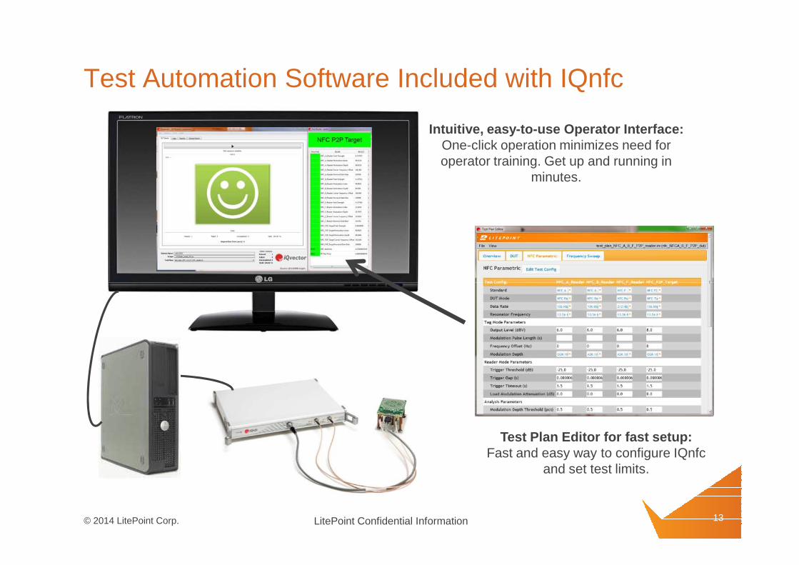
Test Automation Software Included with IQnfc
Intuitive, easy-to-use Operator Interface: One-click operation minimizes need for operator training. Get up and running in
minutes.
© 2014 LitePoint Corp. LitePoint Confidential Information 13
Test Plan Editor for fast setup: Fast and easy way to configure IQnfc
and set test limits.

Manual Test Software Included with IQnfc
User friendly GUI for detailed RF parametric results: Transceiver mode and Frequency sweep mode
© 2014 LitePoint Corp. LitePoint Confidential Information 14
Detailed waveform shape and modulation parameters

IQnfc Summary
• Captures key performance parameters that must be measured in production:- Resonant frequency, Q Factor, Field Strength, Load Modulation Amplitude
• High-throughput solution:- Single insertion testing; 5 second typical test time- Less time than typically used for multi-insertion, pass/fail testing
© 2014 LitePoint Corp. LitePoint Confidential Information
• Deploys in minutes:- Single universal test head covers all key standards- Utilizes simplified signaling layer to eliminate need for DUT drivers- All cables included
15