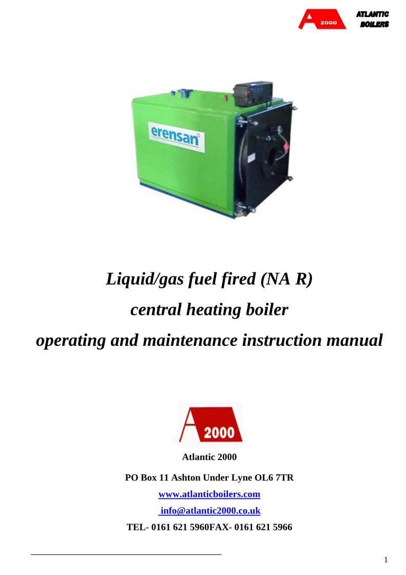
liquid/gas fuel fired (na r) central heating boiler ... · central heating boiler operating and...
TRANSCRIPT
1
Liquid/gas fuel fired (NA R)
central heating boiler
operating and maintenance instruction manual
Atlantic 2000
PO Box 11 Ashton Under Lyne OL6 7TR
www.atlanticboilers.com
TEL- 0161 621 5960FAX- 0161 621 5966

2

3
liquid/gas fuel fired (NA R)
central heating boiler
operating and maintenance instruction manual

4
MAKE SURE THE BOILER PERSONNEL READS THIS MAINTENANCE PROCEDURE!

5
CONTENTS
o Properties of liquid/gas fuel fired boilers...................……………… 6
o Manufacturing and testing standards applied........…0………… . 6
o Introduction.............................................................………………………………..7
o Boiler dimension...................................................................................................8
o Boiler operating personnel…………………………………………………. 9
o Transportation and temporary storage……………………………….. 9
o Boiler installation………………………………………………………………..10
o Burner selection and installation………………………………………... 12
o Fuel selection and storage ………………………………………………… 12
o Filling the system with water……………………………………………... 13
o Preparation of the boiler for operation……………………………….. 14
o Safety rules………………………………………………………………………… 14
o Putting boiler in operation………………………………… 16
o Heating system adjustments……………………………………………… 18
o Discharge of boiler water……………………………………………………19
o Taking boiler out of operation…………………………………………… 20
o Prevention of low temperature corrosion…………………………. 21
o Inspection and maintenance of boiler……………………………….. 22
o General maintenance...............................................…………………………...22
o Hydraulic test........................................................………………………………...23
o General boiler failures...........................………………………....................... 24
o Boiler control panel installation instructions.......……………....... 26
o Control panel dimensions..............................…………….…………………27
o Boiler control panel …………………………………………………………... 28
o Electrical schema……........………………………………………………….... 28
o System circuit schema(sample…………………………... 31
o Boiler feed water and boiler water chemical char………… 32
o Boiler water for hotwater boilers…………………………. 33
o Boiler life span..........................................................……………………………..33
6
FEATURES OF BOILERS
• By virtue of pressurized combustion, the flame is reversed within the combustion chamber.
• Gases and half-burned fuel particles that meet the flame a second time are re-burned and converted
to heat and flue gases are annihilated totally.
• The heat of bright flame formed in the combustion chamber by means of the double pass
concentrated combustion is transferred from the combustion chamber to the water via radiation heat
transfer.
• Flue gas turbulators increase the speed of the smoke and gases in the flame tubes and enable the
maintenance of an optimal-level convection heat transfer.
STANDARDS APPLIED TO MANUFACTURING AND TESTING
NAR 60 – NAR 800 RANGE BOILERS
TS EN 303-1
TS EN 303-2
TS EN 303-3
TS EN 304
NAR 1000 – NAR 2500 RANGE BOILERS
TS 497
TS 4040
TS 4041

7
INTRODUCTION
9
10
8 7 6 45 123
11
12
1. Chimney duct outlet
2. Smoke box
3. Expansion line
4. Cold water return
5. Hot water outlet
6. Control panel
7. Door hinge
8. Handle
9. Observation port
10. Burner adapter flange
11. Drain/filling nozzle
12. Condensate drain nozzle

8
BOILER DIMENSION

9
BOILER OPERATING PERSONNEL
Boiler operating personnel (boiler operator) should have a knowledge of general boiler failures and repair,
and also must know very well the tasks and working principles of all the measurement, adjustment, control
and safety devices existing at the installation.
The boiler operator should have an official document (boiler operator certificate) showing that he is
qualified on the points described above.
TRANSPORTATION AND TEMPORARY STORAGE:
• The boiler should be transported, dismantling the top insulation sheet and using appropriate
equipment utilizing the lifting and transportation points on it.
• For horizontal movement; where it is not possible to utilize a crane, horizontal displacement is
possible through controlled sliding on pipes.
• The boiler should be protected against mechanical blows and collisions during loading,
transportation and unloading.
• It must be protected against damages resulting from moisture and external mechanical factors that
may arise during temporary storage before transportation and installation.
MAKE SURE THE BOILER PERSONNEL HAVE BOILER OPERATING CERTIFICATES!
USE THE BOILER IN COMPLIANCE WITH THE WARNINGS AND
RECOMMENDATIONS IN THIS MANUAL !

10
BOILER INSTALLATION
• Install the boiler in the boiler room at the installation site on a foundation elevated from the floor.
• Make the boiler mechanical connections as per the piping circuit diagram.
• Boiler installation site should conform to related local standards and regulations. It must have a door
opening towards the outside, a fresh air inlet duct at floor level and a polluted air discharge chimney
duct at ceiling level (apart from the boiler chimney). The door and the window frames must be of
non-flammable material.
• The burner, the boiler control panel (if any) and the pre-heater connections should be performed by
eligible technical personnel in compliance with the burner user manual and vendor installation
diagram.
• The boiler should be used with the boiler control panel. (We recommend a thermometer to be
mounted on the boiler return collector or on the return pipe.) A hydrometer (open expansion) or
manometer (closed expansion) must be mounted on the boiler outlet pipe or collector.
• The boiler may be used in open or closed expansion system. If used in closed expansion system;
closed expansion tank must be used, suitable for the total boiler and central heating system water
volume, at building static water height pressure with gas side pressure adjusted. The closed
expansion tank must be connected to the safety pipe directly on the boiler or to the main boiler outlet
or return line pipe on condition of non-existence of a closure valve. Boiler operation pressure *
Safety valve with 1,05 bar pressure must be used.
• More than one boiler should not be connected to the same chimney.

11
INSULATION CASSETTE INSTALLATION
2
5
4
3
1
6
• Install the side insulation cassettes, numbers 2 and 3, on the boiler. Make sure the skirts on the side
cassettes sit well into their sockets.
• Mount the top insulation cassette, number 4, so that the lower skirt sits perfectly into the socket.
• After mounting cassette number 4, mount top insulation cassette number 5 the same way.
12
BURNER SELECTION AND INSTALLATION
To achieve efficient combustion, the burner to be attached to the boiler should be selected in compliance
with the combustion chamber defined in the boiler technical specifications section.
During the installation of the burner, care should be shown to match the nozzle axis with the combustion
chamber axis.
To prevent entry of excess air into the combustion chamber from outside, the burner installation should be
performed carefully to prevent leakage.
The fuel used for operating should comply with burner manufacturer recommendations.
Select a suitable burner conforming to Nominal power of the boiler, meeting the counter pressure of the
boiler (at nominal capacity). When ordering a boiler, inform the related sales personnel about the burner
selected, to ensure that the boiler door and connection flange are designed in compliance with the burner.
FUEL SELECTION AND STORAGE:
• Fuel complying with the characteristics indicated in the burner user manual or burner vendor
catalogues should be obtained.
• Fuel transfer lines should conform to current technical specifications, regulations and standards. The
fuel tank-burner axis levels should not exceed figures specified in the burner user manual.
• Fuel tanks should conform to standards. A wall must exist between the fuel tank and the boiler.
• If fuel oil is being used (especially of a heavier group), the necessary arrangements and heating
installation should be prepared for flow of fuel from the tank to the burner.
BEFORE OPENING THE FRONT DOOR, STOP THE FAN AND SHUT DOWN FAN
PANEL POWER!

13
FILLING THE SYSTEM WITH WATER
The boiler should be filled with water before operation. The boiler should not be operated before it is filled
with water.
To fill the boiler with water, the main distribution and collection pipes, the boiler feeding pipes, installation
column valves should be opened fully, water should be let in from the filling/discharge tap and it should be
filled slowly until water starts coming from the monitor pipe of the Expansion Tank. In closed expansion
systems, during water filling from boiler filling/discharge tap, the air discharge tube valves and mechanical
air vents should be opened and then closed when it is observed that the incoming water does not have
bubbles. When the air tube at the top most level of the installation or at the roof is completely filled with
water, filling will be completed.
The circulation pump should not be operated during the filling process.
The expansion tank connections should conform to the installation circuit diagram.
DO NOT OPERATE BOILER WITHOUT WATER!
14
PREPARATION OF BOILER FOR OPERATION
The boiler room must be designed to meet the combustion air requirements of the boiler.
The boilers should be completely cleaned from internal and external dust, soot, etc.
The smoke channel, smoke pipe and chimney cleaning doors should be checked and leakages should be
prevented.
The fuel heaters (in liquid fuel boilers) should be checked for soundness.
The fuel filters should be cleaned, heater thermostats should be set to correct value, fuel valves should be set
fully open.
The fuel combustion system should be reviewed with respect to the system's working principles and each
element should be controlled for proper operation.
The boiler explosion door should be checked for proper operation.
Boiler safety devices (manometer, hydrometer, safety valve, visual and sound warning system etc.) should
be reviewed to ensure proper operation.
SAFETY RULES
• Do not use the boiler for any other than outside hot water production for closed circuit heating
system.
• Use the boiler complying with warnings and recommendations in this procedure.
• Have the heating system installed by authorized personnel.
• Have the boiler electrical connections made by authorized personnel.
• Do not operate boiler without water.
15
• When opening the front door, shut off the burner and shut down burner electricity.
• Make sure the boiler personnel are certified boiler operators.
• Do not use hard water in heater circuit.
• Boiler water temperature is designed for 90-700C. Install a safety system to prevent water the
temperature from exceeding 1000C.
• Perform the inspection and maintenance activities of the boiler thoroughly.
• The boiler chimney should be built in compliance with chimney building rules. Air brick and
briquette should not be used in boiler chimneys.
• In closed expansion systems, the expansion tank gas pressure should be checked to be equal to that
of the building static water height and the operation of the safety valve should be tested at opening
pressure.
• Have the initial operation of the burner performed by authorized service of related burner company.
The burner capacity adjustment should be made as per the label capacity of the boiler and the boiler
efficiency value stated by the manufacturer firm for the boiler. A burner adjustment above the boiler
label value should not be allowed.
• If abnormal noises are heard from the boiler or the installation, the burner should be stopped
immediately and the fuel inlet should be closed. The investigation and repair of the malfunction
should then be made.
• If leakage and seepage is observed in the burner fuel connection and transfer lines, the burner must
be stopped immediately and lines valves must be closed. If natural gas and LPG is used, use a
leakage detecting device in the boiler room and a system that will stop fuel transfer from the main
inlet.

16
• If LPG is used, when icing and dew is observed on the fuel pipes due to the liquidizing of residual
gas in fuel pipes from the previous night especially on cold days, the burner should absolutely not be
switched on. The LPG should be carefully discharged from the drain tap. (Liquidizing may also
form at normal times due to a problem in the gasification level control or line regulator.)
• In cold climate regions, measures should be taken to prevent the installation water temperature from
falling to freezing temperature. Circulation pump should be operated continuously at workplaces that
are closed at night and during weekends. If heating is to be stopped for a long period of time, the
boiler and system water should be discharged. Antifreeze should not be used. (Antifreeze causes
corrosion and a decrease in water thermal capacity.)
• If the burner malfunctions, burner computer reset button should not be pressed more than two times.
If the burner still does not work, the related authorized service should be called.
PUTTING BOILER IN OPERATION
• Before the liquid/gas fuel hot water boiler is operated, the existence of the following conditions
should be controlled:
• The liquid fuel in main fuel tank or the daily fuel tank should be heated to the required temperature
turning on the heater circuit.
• The valves on the liquid fuel circuit should not be opened fully.
• Burner nozzle should be selected to suit burner and boiler capacity.
• The pre-heater on the burner should be filled with liquid fuel and any air in it should be discharged.
• The boiler thermostat should be adjusted to the suitable value.
• It should be made sure that the heating system is filled with water.
• The system should be filled with water and all the valves (except stand-by circulation pump and the
by-pass valve) should be checked to be open. Air should be discharged from the air valves and air
vents in the system. Circulation pump should not be operated during air discharge.
17
• Circulation pump should be started.
• The burner should be started from the switch on burner power panel.
• After the burner is running, nozzle pressure should be adjusted to burner and boiler capacity.
• When the boiler is in steady state (1-1.5 hours after the burner has started), burner air adjustment
should be made using the flue gas analyser device.
• In the case of gas fuel burner, fuel cut-off valves are opened and the burner is started. In fuel-oil
usage, the burner is started after the fuel is heated in the pre-heater tank.
• Fuel quantity per hour is calculated with the formula B=Qk/(Hu*η ).
B Fuel quantity per hour [kg/h],[Nm3/h]
Qk: Boiler capacity kcal/h,
Hu: Fuel lower thermal value [kcal/kg],[kcal/Nm3]
η : Efficiency
• If the boiler water is overheated, the circulation pump should be checked. (It may be turning in
reverse due to misplaced connectors.) If that does not bring a solution, the burner should be stopped
and the installation should be checked.
• Open the boiler door carefully.
• Protect the front door and the combustion chamber bottom pipe refractory surface from collusion
with hard objects (skewer, brush arm, turbulence makers, etc.).
• During the initial firing of the boiler after manufacturing, run it at a 25-30% capacity setting for
about 2 hours to let the moisture in the cover refractory be disposed of in a healthy manner.
• Use a burner barrel of suitable length in your boiler.
HAVE THE INSTALLATION OF THE HEATING SYSTEM DONE BY AUTHORIZED
PERSONNEL!
18
HEATING SYSTEM ADJUSTMENTS:
The boiler circulation pump should be checked for proper selection and adjustment.
a- Pump flow ;
Qp:Pump flow.
Must be calculated with the formula Qp:Qk/[Cp*(t g-td)] [lt/h].
Qk: Boiler capacity kcal/h
Cp: Water specific heat 1 kcal/kg
is taken as tg-td=20 °C (in 90/70 °C system)
b-Pump pressure ;
Hp=mSS. It must be greater then the critical circuit pressure of the building.
The pump selection should be approved by the (Mech. Eng.) responsible for the building project and the
technical application. Where a project and calculations do not exist or are not available, regulations can be
made by placing thermometers, one each, on the boiler flow and return lines, a manometer to the circulation
pump exit and by adjustments with the help of the related pump curve, through the circulation pump valves
so that the water temperature difference between flow and return lines is 200C. In the case of big pump
selection, the outflow-return temperature difference will stay below 20o C and boiler outflow temperature
may not rise, and in the case of small pump selection, the flow and return temperature difference will be
over 20 0 C and the high and remote radiators may not function efficiently enough.
Every morning, the water level and pressure should be checked from the hydrometer or manometer on the
boiler. If it is below the normal value, water should be added while the boiler is cool. If it is a closed
expansion system, the closed expansion tank gas pressure should be checked to be equal to the static water
height of the building. This control should be done on the expansion tank manometer if it is present, if not, it
should be done from the gas side nozzle with a air pressure tester.
If the pressure is excessive, it should be discharged from the related nozzle, if it is insufficient, nitrogen gas
should be added by the expansion tank authorized service.
If water comes out from the valve during the check instead of gas or air, this means the tank diaphragm is
torn and it should be changed by contacting an authorized service.

19
DISCHARGE OF BOILER WATER
• After a season’s utilization, the boilers should be cleared of gasket remains, mud and residue in the
heating system.
• The blind flanges at the lowest level of the main distribution and collection reservoir and the boiler
filling-discharge tap are removed and the system and boiler water is rapidly flushed out.
• The emptied boiler water surface (internal surface of boiler) is cleaned with pressurized water.
• After the cleaning operation (as explained in the article filling of the system with water at page 13)
the installation must be filled with water.
• The boiler water should not be discharged at any time except pre-operation cleaning and water
should not be added to the boiler except for the purpose of compensating any depletion in the
expansion tank.
TAKING BOILER OUT OF OPERATION
The taking of boiler out of operation should be as follows:
• The burner is stopped and boiler surfaces are cooled.
• The soot and smut in the boiler (the cover, smoke chest and the smoke pipes) should be cleaned.
• The cleaned surfaces should be checked under strong light to detect damages like leakages, oozing,
cracks, etc. If such damages exist, the authorized services are notified and the necessary repairs are
done.
• The liquid fuel between the burner and the main fuel tank should be discharged and the fuel system
should be cleaned with kerosene, diesel oil.
• Active lime should be sprinkled into the combustion chamber, smoke pipes and smoke channels.
• The chimney cleaning flap should be brought to fully open position.
• The damaged heat insulation should be repaired.
20
• The burner maintenance should be done as per manufacturer recommendations.
• During non-operational period, the boiler room temperature should be kept at min. +5o C.
• The boiler and system water should not be discharged if not necessary. At the end of season,
hydrazine residual or similar protective chemical additive should be added to system water, to
prevent negative effects of the oxygen in water on the metal surfaces.
PERFORM FULL CONTROL AND MAINTENANCE OF THE BOILER!
21
PREVENTION OF LOW TEMPERATURE CORROSION:
• The boiler pipes should not be allowed to burst due to low temperature corrosion formation. To
prevent this:
• Liquid fuel with low sulphur content should be used.
• To prevent condensation of the gasses that pass from the boiler surfaces and the smoke pipes,
boiler water outlet temperature should not drop below 60o C and smoke gas temperature below 70o
C.
• 3-way or 4-way Valves must be used in the heating system.
• Soot and lampblack collection must not be allowed on boiler heating surfaces (furnace, smoke pipes,
smoke box), cleaning should be done as frequently as possible.
• The burner should not be stopped and started frequently.
• Combustion should be controlled and ensured to be efficient. The burner settings should be done by
the authorized service and if a re-setting is required, the related burner service should be contacted.

22
INSPECTION AND MAINTENANCE OF BOILER
1. General Maintenance
Heating system boilers should be subjected to general maintenance at least once a year. The following points
should be checked during general maintenance.
• The operation of boiler armatures (thermostat, thermometer, hydrometer / manometer) should be
observed continuously and in case of malfunction the required controls should be done and if needed,
they should be changed. Heat transfer should be improved by filling the thermometer wells with thin
lubricant.
• All connections in the system should be controlled for proper insulation, leakages and oozing should
be repaired and if needed, the valve gaskets should be reinforced.
• The boiler front big door and the rear smoke chest insulation elements should be checked
continuously; if leakage exists, the tightening elements and nuts should be tightened in balance; if
leakage is not stopped, gasket/sealant should be changed or our authorized services should be
contacted. Grease the bolt screws and nuts of tightening elements.
• Perform the cleaning of the boiler combustion chamber, smoke pipes and smoke chest at least every
15 days in the case of liquid fuel usage, and at least every 60 days in the case of gas fuel usage. The
turbulators should be taken out and all pipes should be cleaned with a suitable mop. Turbulators
should be reinstalled after cleaning. For full boiler efficiency, all turbulators should be installed.
• At the end of season, the boiler should be cleaned fully, as in periodical cleaning. Boiler heating
metallic surfaces should be protected against oxidation by applying transformer oil or a thin metallic
lubricant.
• The boiler and system water should not be discharged if it is not a necessity. At the end of season,
hydrazine residual or similar chemical protective additive should be added to system water, to
prevent negative effects of the oxygen in water on the metal surfaces.
• Temperature gauges are compared to a calibrated thermometer.

23
• Safety elements, outlet and return safety pipes and safety valves are checked for proper operation.
• The mud and residuals at bottom of liquid fuel tanks are cleaned.
• The controls described in article on taking boiler out of operation, are performed.
2. Hydraulic Test
Boiler parts such as the smoke pipe, nozzle, tube-sheet should pass a hydraulic test under an authorized
mechanical engineer’s supervision, when replaced or every 5 years for control purposes.
For boilers under 1000kW:
• Close all outlets and inlets with blind flanges except one outlet/return pipe left open.
• Let water into the boiler from the filling/discharge tap until water comes from the vent left open.
• Also plug the open vent with a blind flange.
• Pressure the boiler to 1.3 times the design pressure. Wait 20 minutes and then check for drop in
pressure, leakage, oozing and permanent form changes.
For boilers over 1000kW:
The procedures described above are applied; test pressure is taken as 1.5 times the design pressure.

24
GENERAL BOILER MALFUNCTIONS
Malfunction
Symptom
Reason Solution
No firing • Burner
malfunction
• Follow burner
manufacturer
recommendations.
Dark black
smoke from
chimney
• Excess air
coefficient is
low
• Circuit voltage
low
• Check the fresh air
entering the boiler room
or burner air setting.
• Voltage drop will cause
motor revolutions to
drop and result with a
low fuel-air mixture.
Drumming
noise in
boiler water
compartment
• Air in system. • Discharge the air.
Overheating
in boiler
water
• Circulation
pump
malfunction.
• Thermostat
malfunction
• Check circulation pump
for reverse turning.
• Check boiler
thermometer for proper
operation.
For malfunctions listed above, boiler operator personnel intervention is sufficient. For malfunctions apart
from these, contact our authorized services.
25
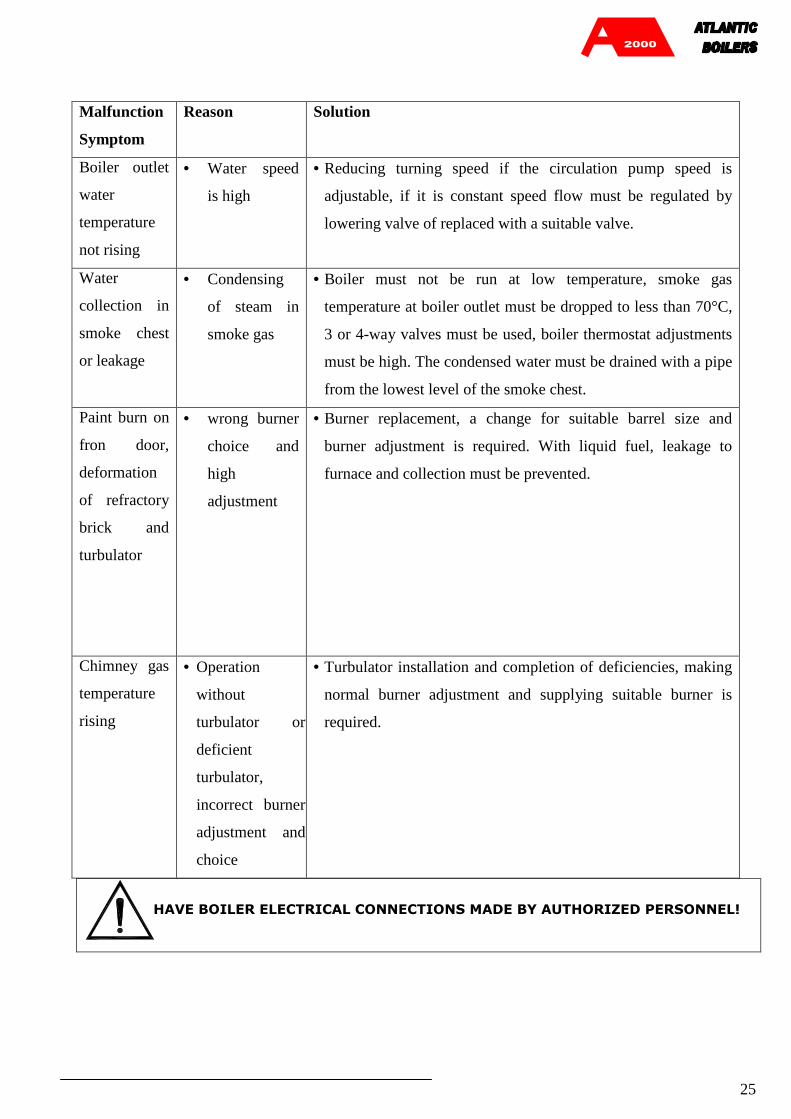
Malfunction
Symptom
Reason Solution
Boiler outlet
water
temperature
not rising
• Water speed
is high
• Reducing turning speed if the circulation pump speed is
adjustable, if it is constant speed flow must be regulated by
lowering valve of replaced with a suitable valve.
Water
collection in
smoke chest
or leakage
• Condensing
of steam in
smoke gas
• Boiler must not be run at low temperature, smoke gas
temperature at boiler outlet must be dropped to less than 70°C,
3 or 4-way valves must be used, boiler thermostat adjustments
must be high. The condensed water must be drained with a pipe
from the lowest level of the smoke chest.
Paint burn on
fron door,
deformation
of refractory
brick and
turbulator
• wrong burner
choice and
high
adjustment
• Burner replacement, a change for suitable barrel size and
burner adjustment is required. With liquid fuel, leakage to
furnace and collection must be prevented.
Chimney gas
temperature
rising
• Operation
without
turbulator or
deficient
turbulator,
incorrect burner
adjustment and
choice
• Turbulator installation and completion of deficiencies, making
normal burner adjustment and supplying suitable burner is
required.
HAVE BOILER ELECTRICAL CONNECTIONS MADE BY AUTHORIZED PERSONNEL!

26
BOILER CONTROL PANEL INSTALLATION INSTRUCTIONS
• Flax the ½” brass wells supplied with the KP (1 for KP1, 2 for KP2 3 for KP3) and install them
on the sleeves on the boiler with proper insulation. Stop the empty sleeves with ½” blind plugs.
• Disassemble the KP body into two pieces, removing the 4 connection screws. Cut and remove
the marked 375x48 mm section at the base. Pass the thermometer and thermostat sensors through
this gap and place them (at most 2 each) in the wells.
• Adjust KP lower body so that it centers the boiler outlet pipes axially and so that it will not pass
end of KP front isolator sheet, drill the screw points marked on 410 x 65mm axis measures with a
4mm tip, concurrently with the upper insulation sheet.
• Make the electrical connection between the KP exit contact and burner contact, complying with
the wiring diagram (with the number of connections) with 0.75mm2 cable. Open enough
positions in the cross sectional area behind the KP for cable pass-through.
• Securely screw the KP lower body onto the upper isolator sheet of the boiler with 4 4.2x13mm
metal sheet screws.
• Put the upper body of the KP in place and close it by tightening with 4 screws.
• Ask the operating personnel to fill the boiler and system with water. When the boiler and system
is filled with water, expansion system is controlled, the circulation pump is seen to be
operational, you may power the control panel.
• Make the sequential controls on the KP and declare that the burner may be started by the
authorized service technician. Supervise the operation of the burner by the related technician and
make the functional controls of the KP elements.
• When no adverse situations arise as a result of the functional controls and KP elements are
observed to perform their tasks, you can set the KP operational.
• For problems and complaints related to the KP contact Atlantic 2000

27
CONTROL PANEL DIMENSIONS
Control panel external dimensions
480
147
175
Control panel lower base installation dimensions
410
375
65 48
PLATE TYPE SCREN (4,2x13mm)
SECTION TO BE EMPTIED

28
KP-1 control panel display
4
5
2
1
3
7
6
1. Manual on-off switch
2. Fuse (6A)
3. Safety thermostat (with manual reset)
4. Boiler water thermometer
5. Burner ON-OFF switch (1. Stage)
6. Thermostat in circuit signal
7. Limit thermostat
KP-1 ELECTRICAL WIRING DIAGRAMME
KONTROL PANELI
S1
BRÜLÖR EMNÝYET DEVRESÝ
1
N(MP)
N(MP)
4
5
F
1SE
10 2 0C
1TE
BRÜLÖRKLEMENSI
KLEMENSI2
T1
1
2
1 C
1
TH1:LiMiT TERMOSTATI DEVREDE SiNYALi
T1 :LiMiT TERMOSTATI
TE :EMNIYET TERMOSTATI (Resetli)S1 :iSLETME SALTERi
SE :MANUEL ON-OFF ANAHTAR
TH1
F :SiGORTA

29
KP-2 control panel display
4
5
6
2
1
3
8
7 9
10
1. Manual on-off switch
2. Fuse (6A)
3. Safety thermostat (with manual reset)
4. Boiler water thermometer
5. Burner ON-OFF switch (1. Stage)
6. Burner ON-OFF switch (2. Stage)
7. I. Stage in circuit signal
8. Ii Stage thermostat
9. II. Stage in circuit signal
10. II. Stage thermostat
KP-2 ELECTRICAL WIRING DIAGRAMME
2.KADEMEBRÜLÖR
1
N(MP)
N(MP)
0
4
5
6A
SIGORTA
1SE
1 2
BRÜLÖR1.KADEME
S1
0C
1TE T1
1
2
1
2 3
C
1S2
1
2
0 1
BRÜLÖRKLEMENSI
KLEMENSIKONTROL PANELI4
T2 1
C
TH2
SE :MANUEL ON-OFF ANAHTARTE :EMNIYET TERMOSTATI (Resetli)
T1 :I.KADEME TERMOSTATITH1
T2 :II.KADEME TERMOSTATI
F :SiGORTA
S1 :I.KADEME SALTERi
TH1:I.KADEME DEVREDE SiNYALiS2 :II.KADEME SALTERi
TH2:II.KADEME DEVREDE SiNYALi

30
KP-3 control panel display
4
6
5
3
1
27
8
9 11 13
10 12
1. Manual on-off switch
2. Fuse (6A)
3. Safety thermostat (with manual reset)
4. Boiler water thermometer
5. Burner ON-OFF switch (1. Stage)
6. Burner ON-OFF switch (2. Stage)
7. Burner ON-OFF switch (3. Stage)
8. I. Stage in circuit signal
9. II Stage thermostat
10. II. Stage in circuit signal
11. II. Stage thermostat
12. III. Stage in circuit signal
13. II. Stage thermostat
KP-3 ELECTRICAL WIRING DIAGRAMME
N(MP)
N(MP)
1
0 1 2
SE
1
1.KADEMEBRÜLÖR
TE4
5
21
1 1C 0
S1
BRÜLÖR2.KADEME
2 3
1T1
C
2
10 1
S2
4 65
BRÜLÖR3.KADEME
1T2
C 0 1
S3T3 12
C1
BRÜLÖR
KONTROL PANELIKLEMENSI
KLEMENSI
F
TH2:II.KADEME DEVREDE SiNYALi
TH1:I.KADEME DEVREDE SiNYALi
TE :EMNIYET TERMOSTATI (Resetli)
S2 :II.KADEME SALTERiT2 :II.KADEME TERMOSTATI
T1 :I.KADEME TERMOSTATIS1 :I.KADEME SALTERi
SE :MANUEL ON-OFF ANAHTARF :SiGORTA
S3 :III.KADEME SALTERiT3 :III.KADEME TERMOSTATITH3:III.KADEME DEVREDE SiNYALi
TH3TH2TH1
31
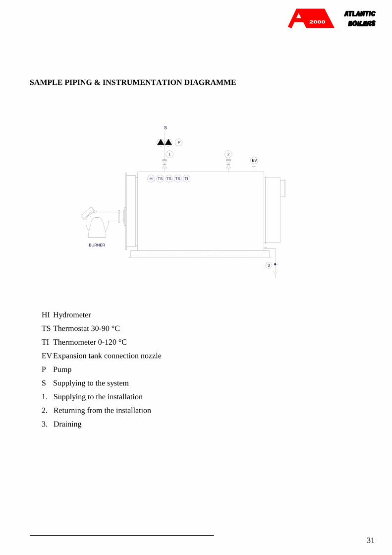
SAMPLE PIPING & INSTRUMENTATION DIAGRAMME
EV
TSHI TS TS TI
1
S
P
2
3
BURNER
HI Hydrometer
TS Thermostat 30-90 °C
TI Thermometer 0-120 °C
EV Expansion tank connection nozzle
P Pump
S Supplying to the system
1. Supplying to the installation
2. Returning from the installation
3. Draining

32
BOILER FEED WATER AND BOILER WATER CHEMICAL CHARACT ERISTICS
Water to be used in Hot Water boilers must comply with the table values indicated below.
To operate a productive and economic boiler, boiler feed water and boiler water must be continuously
controlled and it must be ensured that the chemical conditions required for water are provided.
FEEDWATER FOR HOT WATER
BOILERS
Parameter Unit Make-up water for hot water &
superheated water boilers
bar total range Operating Pressure
MPa total range
Appearance - clear, free from suspended solids
Conductivity at 25 °C µS/cm < 1500
pH value at 25 °C ¹) - > 7,0
Total hardness (Ca +
Mg) mgl/liter(ppm) < 5 [=0,5 Fr.H]
Iron (Fe) mgl/liter(ppm) < 0,2
Copper (Cu) mgl/liter(ppm) < 0,1
Silica (SiO2) mgl/liter(ppm) -
Oxygen (O2) mgl/liter(ppm) -
Oil/grease mgl/liter(ppm) < 1
Organic substances - See clause 5 1) With copper alloys in the system the pH value shall be maintained in the range
8,7 to 9,2 2) 3) 4) If non-ferrous materials are present in the system, e.g. Aluminium, they may
require lower pH value and conductivity, however, the protection of the boiler has
priority. 5) If Phosphate is used; considering all other values higher PO4-concentrations are
acceptable, for instance with balanced or coordinated phosphate treatment (see
also clause 4).

33
BOILERWATER FOR HOT WATER BOILERS
Parameter Unit Boiler water for hot water &
superheated water boilers
bar total range Operating Pressure
MPa total range
Appearance - clear, no stable foam
Conductivity at 25 °C µS/cm < 1500
pH value at 25 °C - 9,0 to 11,5 4)
Acid Capacity up to pH
8,2 mmol/liter < 5
Silica (SiO2) mg/liter -
Phosphate (PO4) 5) mg/liter -
Organic substances - - 1) 2) 3) 4) If non-ferrous materials are present in the system, e.g. Aluminium, they may
require lower pH value and conductivity, however, the protection of the boiler
has priority. 5) If Phosphate is used; considering all other values higher PO4-concentrations
are acceptable, for instance with balanced or coordinated phosphate treatment
(see also clause 4).
Ref : prEN 12953-10, Table 5-1, 5-2; 1998
BOILER LIFE SPAN
The economic life span of hot water boilers has been determined as 10 years. With erensan° brand boilers,
it is possible to go well over the life span stated by the Ministry when the boilers are used in compliance
with operating and maintenance instructions. Therefore, ensure that this operating and maintenance
procedure is read and fully applied by operating personnel.
When the boiler has reached unusable state, remove the junk from usage area in compliance with
environmental procedures.
34
Atlantic 2000
PO Box 11 Ashton Under Lyne OL6 7TR
www.atlanticboilers.com
TEL- 0161 621 5960FAX- 0161 621 5966
ĐB52001-1
This document is subject to change without notice by Atlantic 200