liquid crystals in displays - mit opencourseware
TRANSCRIPT

Liquid Crystals in Displays
Outline
- Liquid Crystals - Building a Liquid Crystal Cell - Liquid Crystal Display Pixel - Passive/Active Matrix Addressing
Image in the public domain
1
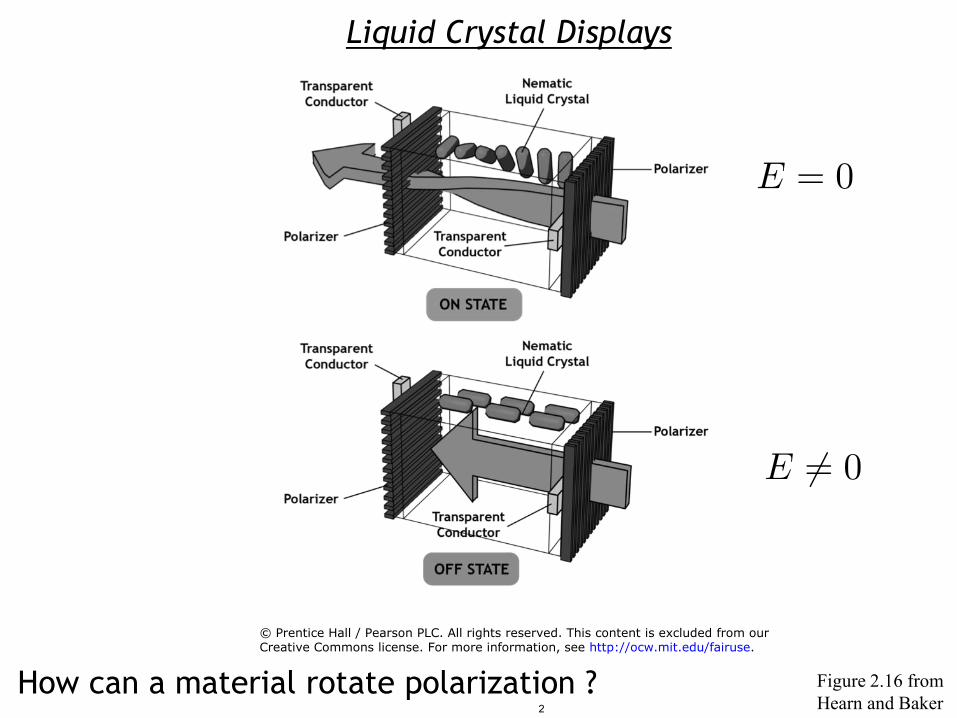
Liquid Crystal Displays
How can a material rotate polarization ? Figure 2.16 from Hearn and Baker
© Prentice Hall / Pearson PLC. All rights reserved. This content is excluded from ourCreative Commons license. For more information, see http://ocw.mit.edu/fairuse.
2
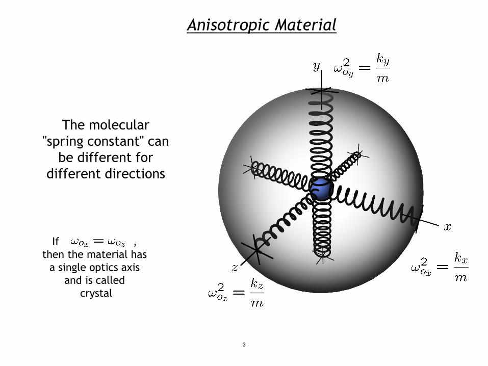
The molecular "spring constant" can
be different for different directions
Anisotropic Material
If ,
then the material has
a single optics axis
and is called
crystal
3

Microscopic Lorentz Oscillator Model
In the transparent regime …
4
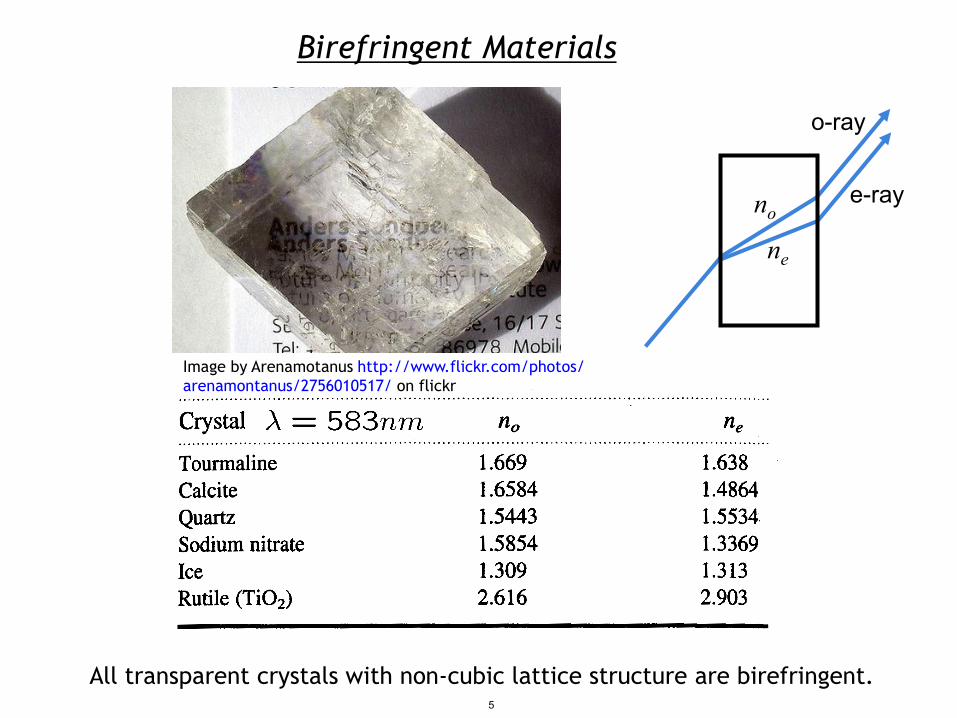
Birefringent Materials
All transparent crystals with non-cubic lattice structure are birefringent.
no
ne
o-ray
e-ray
Image by Arenamotanus http://www.flickr.com/photos/arenamontanus/2756010517/ on flickr
5
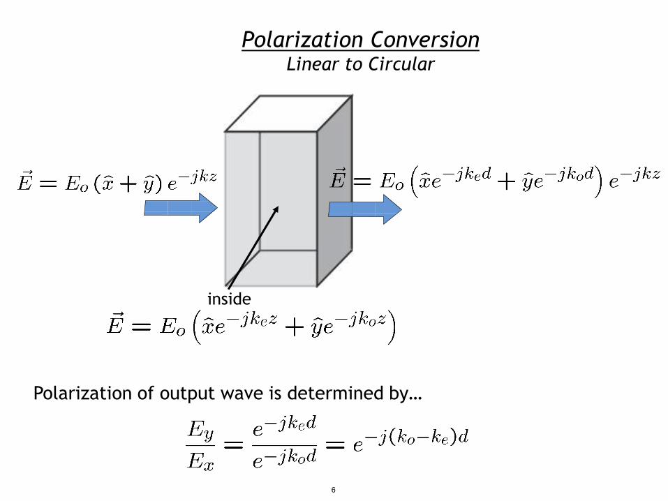
Polarization Conversion Linear to Circular
inside
Polarization of output wave is determined by…
6
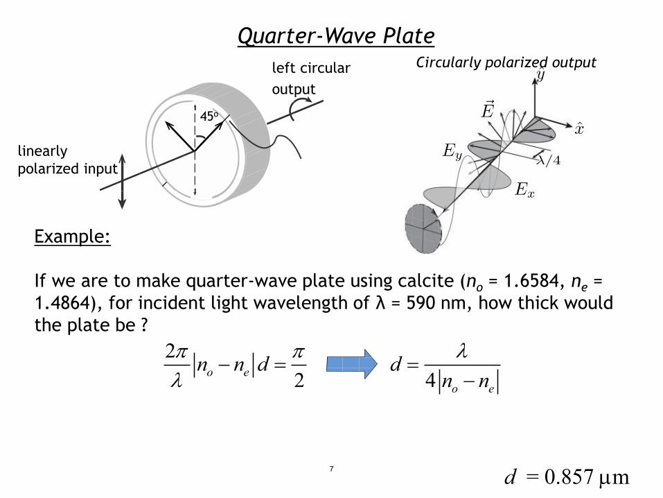
Quarter-Wave Plate
Example:
Circularly polarized output
If we are to make quarter-wave plate using calcite (no = 1.6584, ne = 1.4864), for incident light wavelength of λ = 590 nm, how thick would the plate be ?
22o en n dπ π
λ− =
4 o e
dn nλ
=−
d = 0.857 µm
left circular output
45o
linearly polarized input
7

3D Movies Technology
Polarizer A
Left eye Film or digital source projector
Right eye Film or digital source projector
Polarizer B
Which approach is better ? Linear or circular polarization ?
Image by comedy_nose http://www.flickr.com/photos/comedynose/4482682966/ on flickr
8

A linearly polarized wave can be represented as a sum of two circularly polarized waves
CIRCULAR LINEAR CIRCULAR
9

Circular Birefringence But as the two circular polarizations of light travel through the circular
birefringence material at different speeds, they will be phase shifted when they exit the medium
10
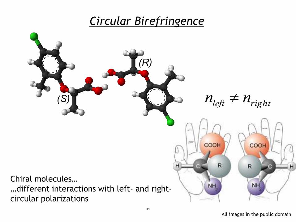
Circular Birefringence
Chiral molecules… …different interactions with left- and right- circular polarizations
nleft ≠ nright
All images in the public domain 11

x-polarized
y-polarized
Polarization Rotation with Circular Birefringence
-
12

Interleaved 3D Movies
Shuttered/ switching polarizer
Left eye source High frame
rate projector
Right eye source
Image by comedy_nose http://www.flickr.com/photos/comedynose/4482682966/ on flikr
13

Liquid Crystal Displays
E = 0
E = 0
Circular birefringence
NO circular birefringence
14

States of Matter
Solid (crystalline): incompressible, no flow under shear crystal = periodic in space
Liquid Crystal: incompressible, flows under shear long range order
Liquid: incompressible, flows under shear very short range order
Gas: compressible
15
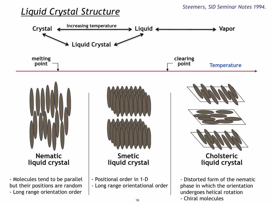
Temperature melting point
Liquid Crystal Structure
clearing point
Steemers, SID Seminar Notes 1994.
- Molecules tend to be parallel - Positional order in 1-D - Distorted form of the nematic but their positions are random - Long range orientational order phase in which the orientation - Long range orientation order undergoes helical rotation
- Chiral molecules
Crystal Liquid Vapor
Liquid Crystal
Nematic Smetic Cholsteric liquid crystal liquid crystal liquid crystal
Increasing temperature
16

Twisting Liquid Crystals
LC ordering is determined by anisotropic boundary conditions (grooves) Light
polarizers
Alignment layers
Voltage S 17
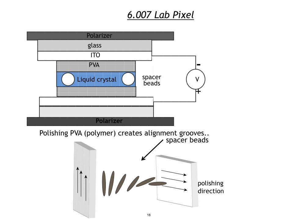
6.007 Lab Pixel
Polishing PVA (polymer) creates alignment grooves.. spacer beads
Polarizer glass ITO PVA -
spacer Liquid crystal V beads +
Polarizer
polishing direction
18

Liquid Crystal Displays
E = 0
E = 0
Figure 2.16 from Hearn and Baker
LC dielectric anisotropy allows control of
molecular orientation by the external E-field. Molecules rotate to
minimize stored energy
What is the physical reason for LC rotation ? 19

Anisotropic Dielectric Constant
- - - - - - - - - - - - - - - - -
-
+ + + + + + + + + + + + + + + + + + + A
d
- - - - - - - - - - - - - - - - -
-
+ + + + + + + + + + + + + + + + + + + A
d
-
+
-
+
-
+
-
+
-
+
-
+
-
+
-
+
-
+
- +
- +
- +
- +
- +
20
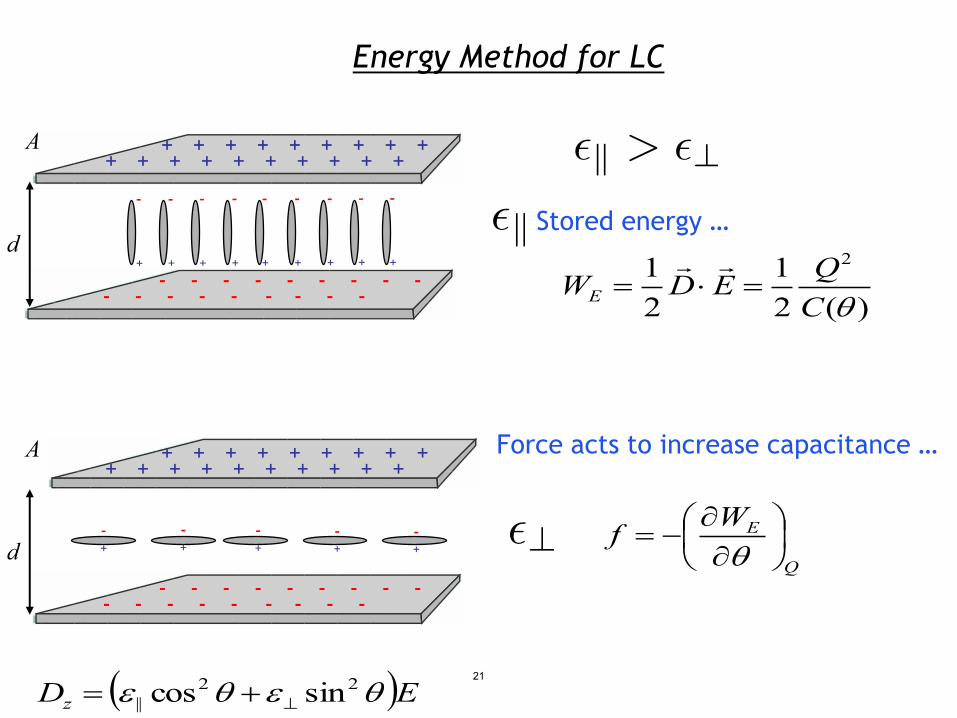
Energy Method for LC
)(21
21 2
θCQEDWE =⋅=
Q
EWf
∂∂
−=θ
Dz = (ε 2θ ε 2|| cos + ⊥ sin θ )E
Stored energy …
Force acts to increase capacitance …
- - - - - - - - - - - - - - - - -
-
+ + + + + + + + + + + + + + + + + + + A
d
- - - - - - - - - - - - - - - - -
-
+ + + + + + + + + + + + + + + + + + + A
d
-
+
-
+
-
+
-
+
-
+
-
+
-
+
-
+
-
+
- +
- +
- +
- +
- +
21

Electro-Optic Response
LC cell is 5 μm to 10 μm thick At 3 V applied dc-bias E–field is 3 to 6 kV/cm
of Twisted Nematic Liquid Crystal Cell
n T=90%
issi
osm
anre
Tiv
atelR
T=10%
Applied Voltage
22
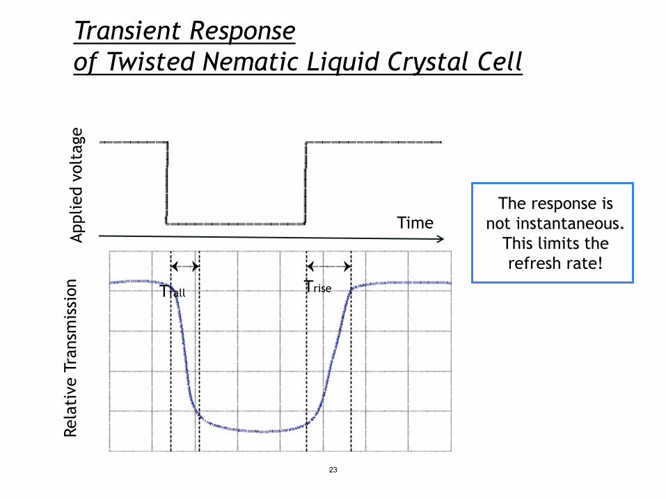
Transient Response
The response is not instantaneous.
This limits the refresh rate!
of Twisted Nematic Liquid Crystal Cell egat
vol
deilp Time
Ap n
issi
o T Trise fall
sman
e Tr
ivat
elR
23
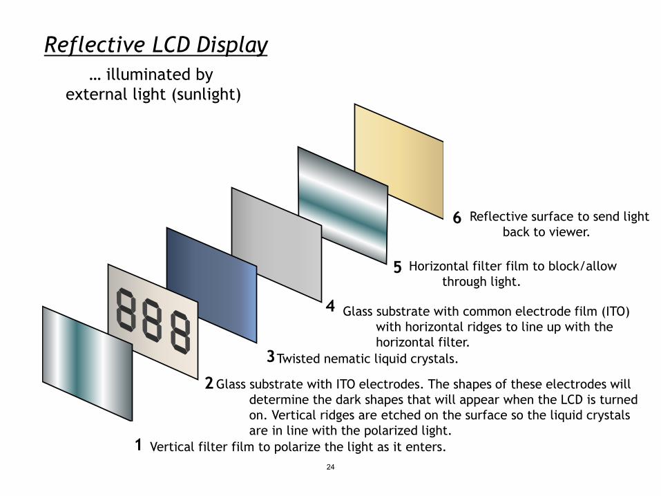
Reflective LCD Display
Reflective surface to send light back to viewer.
Horizontal filter film to block/allow through light.
Glass substrate with common electrode film (ITO) with horizontal ridges to line up with the horizontal filter.
Twisted nematic liquid crystals.
Glass substrate with ITO electrodes. The shapes of these electrodes will determine the dark shapes that will appear when the LCD is turned on. Vertical ridges are etched on the surface so the liquid crystals are in line with the polarized light.
Vertical filter film to polarize the light as it enters.
… illuminated by external light (sunlight)
6
5
4
3
2
1 24

Display Addressing DIRECTLY ADDRESSED MATRIX DISPLAY DISPLAY
v
Common Electrode
Segmented Electrode
HI LO
DISABLE ENABLE
Example: for X=640 x Y480 panel of emissive elements direct addressing 2 x 640 x 480 = 614,400 (2*X*Y) wires matrix addressing 640 + 480 = 1120 (X+Y) wires
Cathode Rows
Active Layers
Substrate
Anode Columns 25

Example of a Color Filter (green)
LCD Display Cross-Section Vertical Fluorescent Polarizing filter backlight Column
Addressing line
Top polarizer
Retardation film Top glass
Column electrodes Liquid crystal Row
Addressing Row electrodes line
Over coating Color filter
Bottom glass Retardation film
Subpixel Bottom polarizer electrode Backlight
Transistor
Pixel ON
Glass plate Front plate
Liquid crystal layer Horizontal
Polarizing filter
26
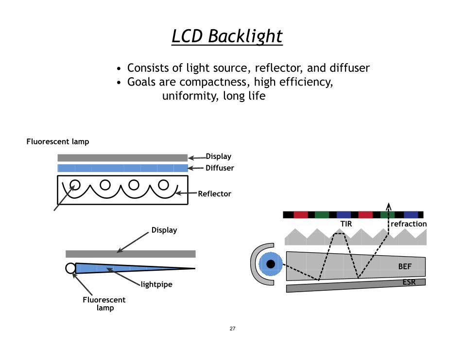
LCD Backlight
• Consists of light source, reflector, and diffuser • Goals are compactness, high efficiency,
uniformity, long life
TIR refraction
BEF
ESR
Fluorescent lamp
Display Diffuser
Reflector
Display
lightpipe
Fluorescent lamp
27

What is Color?
Image is in the public domain Image is in the public domain
λ (m) 103 102 101 1 10-1 10 -9 -10 -2 10-3 10-4 10-5 10-6 10-7 10-8 10 10 10-11 10-12
Radio waves “Hard” X-rays
IR UV
Microwaves “Soft” X-rays
Gamma rays
Visible
28
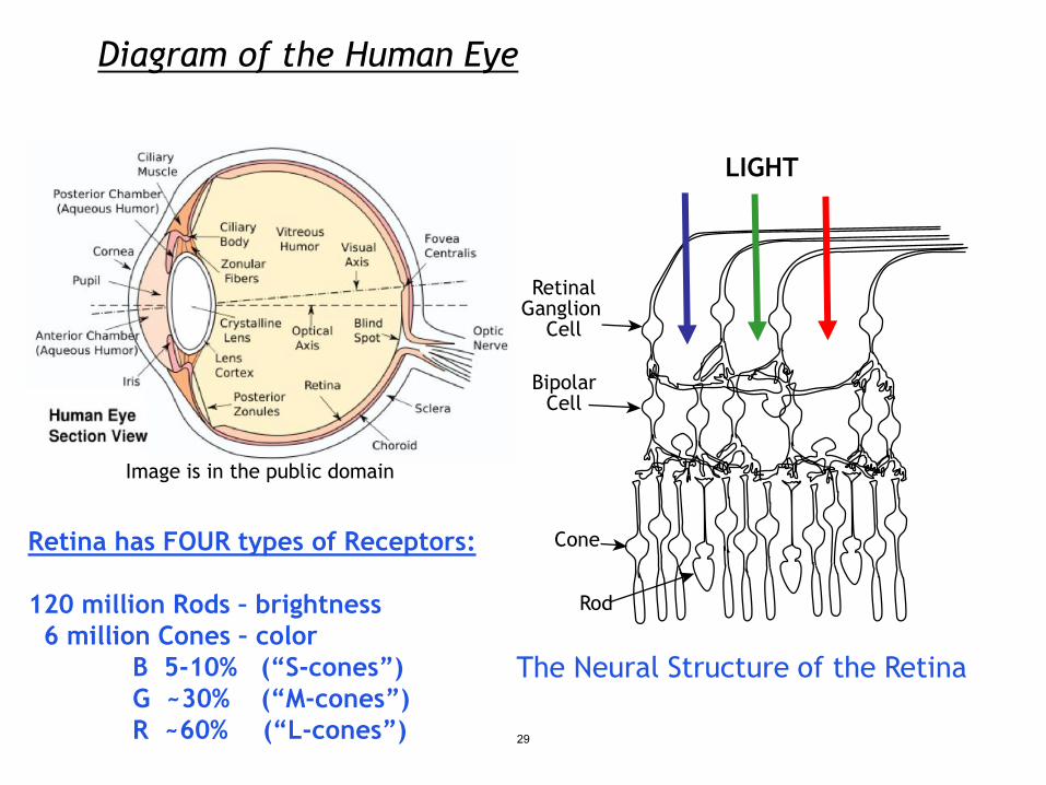
Diagram of the Human Eye
The Neural Structure of the Retina
LIGHT
Retina has FOUR types of Receptors: Cone
Rod
Bipolar Cell
120 million Rods – brightness 6 million Cones – color B 5-10% (“S-cones”) G ~30% (“M-cones”) R ~60% (“L-cones”)
Retinal Ganglion
Cell
Image is in the public domain
29
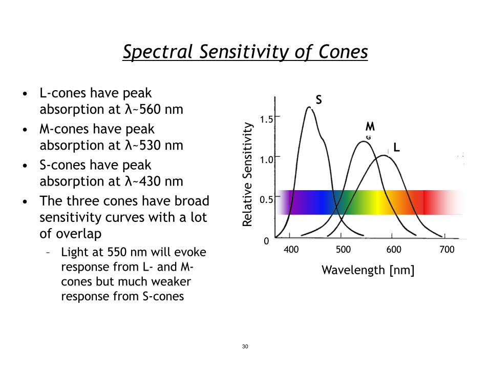
Spectral Sensitivity of Cones
• L-cones have peak absorption at λ~560 nm
• M-cones have peak
yit
absorption at λ~530 nm ivsi
t
• S-cones have peak en
absorption at λ~430 nm e S
• The three cones have broad ivat
sensitivity curves with a lot elRof overlap – Light at 550 nm will evoke
response from L- and M- Wavelength [nm] cones but much weaker response from S-cones
400 500 600 700 0
0.5
1.5
1.0
S
M
L
30
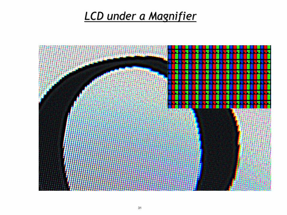
LCD under a Magnifier
31

Polymer Dispersed LCDs – Privacy Glass e suspension Suspended
iv g li+qu id particle
ct n - + -
u ati
d on coc
OFF
ON
Image by University of Michigan MSIS http://www.flickr.com/photos/umich-msis/6443313259/ on flickr
• A standard meeting room with some privacy OFF protection
• Polymer dispersed LCDs allow for changeable transparency
32
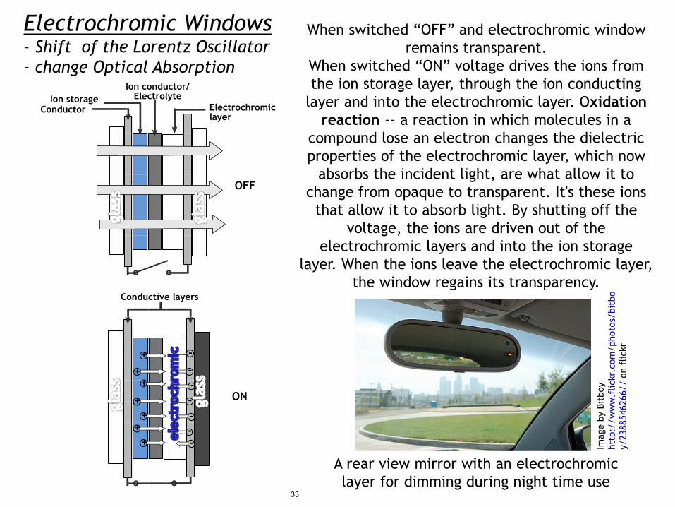
Electrochromic Windows When switched “OFF” and electrochromic window remains transparent.
When switched “ON” voltage drives the ions from the ion storage layer, through the ion conducting
layer and into the electrochromic layer. Oxidation reaction -- a reaction in which molecules in a
compound lose an electron changes the dielectric properties of the electrochromic layer, which now
absorbs the incident light, are what allow it to change from opaque to transparent. It's these ions
that allow it to absorb light. By shutting off the voltage, the ions are driven out of the
electrochromic layers and into the ion storage layer. When the ions leave the electrochromic layer,
the window regains its transparency.
A rear view mirror with an electrochromic layer for dimming during night time use
- Shift of the Lorentz Oscillator - change Optical Absorption
Ion conductor/ Electrolyte Ion storage
Conductor Electrochromic layer
Conductive layers obti/bsotohp r/ k
m ico lfc . nr o k c /ybo
il /f.ti wB wby e //w
:g paIm
tth /238
8546
266
y
OFF
ON
+ + +
+ +
+ +
- - - - - - -
33

MIT OpenCourseWarehttp://ocw.mit.edu
6.007 Electromagnetic Energy: From Motors to LasersSpring 2011
For information about citing these materials or our Terms of Use, visit: http://ocw.mit.edu/terms.