liquid crystal display module - eltron.pl · liquid crystal display module standard product...
TRANSCRIPT

Product No. LR4828 REV. A Page 1 / 19
DENSITRON CORPORATION – PROPRIETARY DATA – ALL RIGHTS RESERVED FORM No. 72-0199 iss. 2.0
LIQUID CRYSTAL DISPLAY MODULE
Standard Product Specification
PRODUCT NUMBER LR4828
INTERNAL APPROVALS Product Manager Engineering Document Control
Date: Date: Date:

Product No. LR4828 REV. A Page 2 / 19
DENSITRON CORPORATION – PROPRIETARY DATA – ALL RIGHTS RESERVED
TABLE OF CONTENTS
1 DESCRIPTION & MAIN FEATURES ...............................................................................4
1.1 DESCRIPTION................................................................................................................4 1.2 MECHANICAL CHARACTERISTICS ..........................................................................4 1.3 MECHANICAL DRAWING ...........................................................................................5
2 ELECTRICAL SPECIFICATION.......................................................................................6 2.1 ABSOLUTE MAXIMUM RATINGS..............................................................................6 2.2 ELECTRICAL CHARACTERISTICS ............................................................................6 2.3 RECOMMENDED LC DRIVE VOLTAGE (VDD-VO).................................................7 2.4 INTERFACE PIN ASSIGNMENT ..................................................................................7 2.5 BLOCK DIAGRAM.........................................................................................................8 2.6 POWER SUPPLY CIRCUIT............................................................................................8 2.7 TIMING CHARACTERISTICS ......................................................................................8 2.8 TIMING CHARACTERISTICS ......................................................................................9 2.9 DD RAM ADDRESS VS. DISPLAY POSITION.............................................................9
3 OPTICAL SPECIFICATION.............................................................................................10 3.1 OPTICAL CHARACTERISTICS..................................................................................10
4 BACKLIGHT SPECIFICATION.......................................................................................12 4.1 BACKLIGHT CHARACTERISTICS............................................................................12
5 QUALITY ASSURANCE SPECIFICATION ...................................................................13 5.1 CONFORMITY..............................................................................................................13 5.2 DELIVERY ASSURANCE ...........................................................................................13
6 RELIABILITY SPECIFICATION.....................................................................................17 6.1 RELIABILITY TESTS...................................................................................................17 6.2 LIFE TIME.....................................................................................................................17
7 PART NUMBER DESCRIPTIONS FOR AVAILABLE OPTIONS ..............................18
8 HANDLING PRECAUTIONS............................................................................................19

Product No. LR4828 REV. A Page 3 / 19
DENSITRON CORPORATION – PROPRIETARY DATA – ALL RIGHTS RESERVED
REVISION RECORD
Rev. Date Page Chap. Comment ECN no.
A 10/23/06 -- -- Initial Standard Product Release, ROHS E3283

Product No. LR4828 REV. A Page 4 / 19
DENSITRON CORPORATION – PROPRIETARY DATA – ALL RIGHTS RESERVED
1 DESCRIPTION & MAIN FEATURES
1.1 DESCRIPTION Dot matrix display module consisting of a Liquid Crystal Display, CMOS driver and controller LSI, printed circuit board and metal support frame and edge type Light Emitting Diode (LED) backlight. Available LC fluids types are: STN (supertwisted nematic).
1.2 MECHANICAL CHARACTERISTICS
ITEM SPECIFICATION UNIT
Module Dimensions 122.2 (W) x 33.2 (H) x 14.9 max.(D) mm
Display Format 1 Line x 16 Characters --
Character Font Format 5 (W) x 7 (H) with attached cursor dots
Duty Ratio 1/16 --
Dot Size 0.92 (W) x 1.1 (H) mm
Dot Pitch 0.98 (W) x 1.16 (H) mm
Character Size 4.84 (W) x 9.66 (H) mm
Active Area 94.84 (W) x 9.66 (H) mm
Viewing Area 99.0 (W) x 13.0 (H) mm
ROHS Compliant Yes

Product No. LR4828 REV. A Page 5 / 19
DENSITRON CORPORATION – PROPRIETARY DATA – ALL RIGHTS RESERVED
1.3 MECHANICAL DRAWING

Product No. LR4828 REV. A Page 6 / 19
DENSITRON CORPORATION – PROPRIETARY DATA – ALL RIGHTS RESERVED
2 ELECTRICAL SPECIFICATION
2.1 ABSOLUTE MAXIMUM RATINGS VSS = 0 V, Ta = 25 °C
Item Symbol Min Max Unit Note
Power Supply Voltage VDD 0 7 V
LC driver supply voltage VDD-Vo 0 10.0 V
Operating Temperature Top -20 +70 °C Note 1,3
Storage Temperature Tst -30 +80 °C Note 2
Humidity: Operating (@40°C, -- -- 65% Note 4
Humidity: Non-operating (@40°C. -- -- 90% Note 4
Note 1: Background colour changes slightly depending on ambient temperature. This phenomenon is reversible. Ta≤70 °C: 75% RH max
Note 2: Ta≤80 °C: 75% RH max Note 3: Tested to 100 hrs. Note 4: Refers to non-condensing conditions. Note 5: It is not recommended to operate EL lamp above 50°C.
2.2 ELECTRICAL CHARACTERISTICS VSS = 0 V, Ta = 25 °C
Item Symbol Condition Min Typ Max Unit
VIHC Ta = 25°C 2.2 -- VDD V Input Voltage
VILC Ta = 25°C -- -- 0.6 V
VOH IOH=0.205mA 2.4 -- -- V Output Voltage
VOL IOL=1.2mA -- -- 0.4 V
Current Consumption * IDD VDD = 5.0V -- 2.4 -- mA
*IDD measurement condition is for all patterns ON

Product No. LR4828 REV. A Page 7 / 19
DENSITRON CORPORATION – PROPRIETARY DATA – ALL RIGHTS RESERVED
2.3 RECOMMENDED LC DRIVE VOLTAGE (VDD-VO)
Temperature STN Ta = -20°C -- Ta = 0°C 4.7 Ta = 25°C 4.4 Ta = 50°C 4.1 Ta = 70°C --
2.4 INTERFACE PIN ASSIGNMENT
No. Symbol I/O Function
1 VSS -- Ground (0V), LED-
2 VDD -- Logic Supply Voltage (+5V)
3 VO -- LC Drive voltage for contrast adjustment
4 RS I Register Select 0: Instruction Register 1: Data Register
5 R/W I Read / Write 0: Data Write (Module ← MPU) 1: Data Read (Module → MPU)
6 E I Enable Signal Active High (H → L)
7 DB0 I/O Bi-directional data bus line 0
8 DB1 I/O Bi-directional data bus line 1
9 DB2 I/O Bi-directional data bus line 2
10 DB3 I/O Bi-directional data bus line 3
11 DB4 I/O Bi-directional data bus line 4
12 DB5 I/O Bi-directional data bus line 5
13 DB6 I/O Bi-directional data bus line 6
14 DB7 I/O Bi-directional data bus line 7
15 VEE I/O Negative voltage input for LC drive (Negative voltage output for modules with on-board negative voltage generator).

Product No. LR4828 REV. A Page 8 / 19
DENSITRON CORPORATION – PROPRIETARY DATA – ALL RIGHTS RESERVED
16 VLED- -- Anode (+) LED backlight input voltage
BL1 VLED+ -- Anode (+) LED backlight input voltage
BL2 VLED- -- Cathode (-) LED backlight input voltage
2.5 BLOCK DIAGRAM
2.6 POWER SUPPLY CIRCUIT
RECOMMENDED VR: 10Kohm ~ 20Kohm
2.7 TIMING CHARACTERISTICS Note: Please reference the manufacturer’s datasheet for the Sitronix ST7066U controller.

Product No. LR4828 REV. A Page 9 / 19
DENSITRON CORPORATION – PROPRIETARY DATA – ALL RIGHTS RESERVED FORM No. 72-0199 iss. 2.0
2.8 TIMING CHARACTERISTICS
Item Symbol Min. Typ. Max. Unit Enable cycle time TcycE 500 - - nS Enable pulse width PWEH 230 - - nS Enable rise / fall time tEr/tEf - - 20 nS Address set-up time tAS 40 - - nS Address hold time tAH 10 - - nS Data delay time tDDR - - 160 nS Data hold time (Write) tDHW 10 - - nS Data hold time (Read) tDHR 5 - - nS Data set-up time tDSW 80 - - nS
2.9 DD RAM ADDRESS vs. DISPLAY POSITION
Character 1 2 3 4 5 6 7 8 9 10 11 --- 14 15 16 Line 1 00 01 02 03 04 05 06 07 40 41 42 --- 45 46 47

Product No. LR4828 REV. A Page 10 / 19
DENSITRON CORPORATION – PROPRIETARY DATA – ALL RIGHTS RESERVED FORM No. 72-0199 iss. 2.0
3 OPTICAL SPECIFICATION
3.1 OPTICAL CHARACTERISTICS
Ta = 25 °C
Item Symbol Condition Min Typ Max Unit Note
0° θ1 CR≥2 -- 30 -- deg 1
180° θ2 CR≥2 -- 30 -- deg 1
90° θ3 CR≥2 -- 40 -- deg 2
Viewing Angle
270° θ4 CR≥2 -- 40 -- deg 2
Contrast Ratio CR Ta = 25 °C 4 -- -- - 3
Tr Ta = 25 °C -- 150 250 Response Time
Tf Ta = 25 °C -- 150 250 ms 4
Driving Method Duty 1/16
LCD Type STN - Positive
Viewing Direction 6:00

Product No. LR4828 REV. A Page 11 / 19
DENSITRON CORPORATION – PROPRIETARY DATA – ALL RIGHTS RESERVED
Note 1: definition of viewing angle θ1 & θ2 Note 2: definition of viewing angle θ3 & θ4
Note 3: definition of contrast ratio (CR)
Driving Voltage(V)
Intensity
Cr Max
100
Vop
Selected Wave
Non-selected Wave
[positive type]
Cr = Loff / Lon
Driving Voltage(V)
Intensity
Cr Max
100%
Vop
Selected Wave
Non-selected Wave
[Negative type]
Cr = Lon / Loff
Note 4: definition of response time
I n t e n s i ty
9 0 % 1 0 0 %
T r
1 0 %
T f
N o n - s e l e c t e d C o n d i t i o n
N o n - s e l e c t e dC o n d i t i o nS e l e c t e d C o n d i t i o n
[ p o s i t i v e t y p e ]
In te n s ity
9 0 %1 0 0 %
T r
1 0 %
T f
N o n -se le c te d C o n d itio n
N o n -se le c te d C o n d itio n S e le c te d C o n d itio n
[N e g a tiv e ty p e ]

Product No. LR4828 REV. A Page 12 / 19
DENSITRON CORPORATION – PROPRIETARY DATA – ALL RIGHTS RESERVED
4 BACKLIGHT SPECIFICATION
4.1 BACKLIGHT CHARACTERISTICS Ta=20°C,60%RH,Darkroom.
Item Symbol Typ. Max. Unit
LED lamp input voltage VLED+ 5 6 Vrms LED lamp input current ILED 190 200 mA Build-in current limiting resistor
R1 - - Ohms, W
External current limiting resistor (recommended)
R2 4.3 Ohms, 1/2W
- Ohms, W
Number of nodes N 19 - -

Product No. LR4828 REV. A Page 13 / 19
DENSITRON CORPORATION – PROPRIETARY DATA – ALL RIGHTS RESERVED
5 QUALITY ASSURANCE SPECIFICATION
5.1 CONFORMITY The performance, function and reliability of the shipped products conform to the Product Specification.
5.2 DELIVERY ASSURANCE
5.2.1 Delivery inspection standards
• IPC-AA610, class 2 electronic assemblies standard
5.2.2 Zone definition
5.2.3 Visual inspection
• Inspect under 2x20W or 40W fluorescent lamp (approximately 3000 lux) leaving 25 to 30 cm between the module and the lamp and 30 cm between the module and the eye (measuring position).
• Appearance is inspected at the best contrast voltage (best contrast is adjusted considering clearness and crosstalk on screen).
• Inspect the module at 45° right and left, top and bottom. • Use the optimum viewing angle during the contrast inspection.
A Viewing area
B Outside viewing area
45°45°
eye

Product No. LR4828 REV. A Page 14 / 19
DENSITRON CORPORATION – PROPRIETARY DATA – ALL RIGHTS RESERVED
5.2.3.1 Standard of appearance inspection Units: mm
Class Item Criteria
Minor Outside & inside package Presence of product no., lot no., quantity Critical
Packing & Label Product must not be mixed with others and quantity must not be different from
that indicated on the label Major Dimension Product dimensions must be according to specification and drawing
Major Electrical Product electrical characteristics must be according to specification
Critical LCD Display
Missing lines or wrong patterns on LCD display are not allowed
Round type: as per following drawing ∅ = (X+Y)/2 Acceptable quantity Size Zone A Zone B ∅<0.1 Any number 0.1<∅<0.2 2 0.2<∅<0.25 1 0.25<∅ 0
Any number
Line type: as per following drawing Acceptable quantity Length Width Zone A Zone B - - W≤0.02 Any number L≤3.0 0.02<W≤0.03 L≤2.5 0.03<W≤0.05 2 - - 0.05<W As round type
Any number
Total acceptable quantity: 3
Minor Black spot, white spot,
dust
Scratch on protective film is permitted Minor Polariser
scratch Scratch on polariser: same as No. 1 ∅ = (X+Y)/2 Acceptable quantity Size Zone A Zone B ∅<0.2 Any number 0.2<∅<0.5 2 0.5<∅<1.0 1 1.0<∅ 0
Any number
Total acceptable quantity: 3
Minor Polariser bubble
X
Y
L
W
X
Y
Product No. LR4828 REV. A Page 15 / 19
DENSITRON CORPORATION – PROPRIETARY DATA – ALL RIGHTS RESERVED
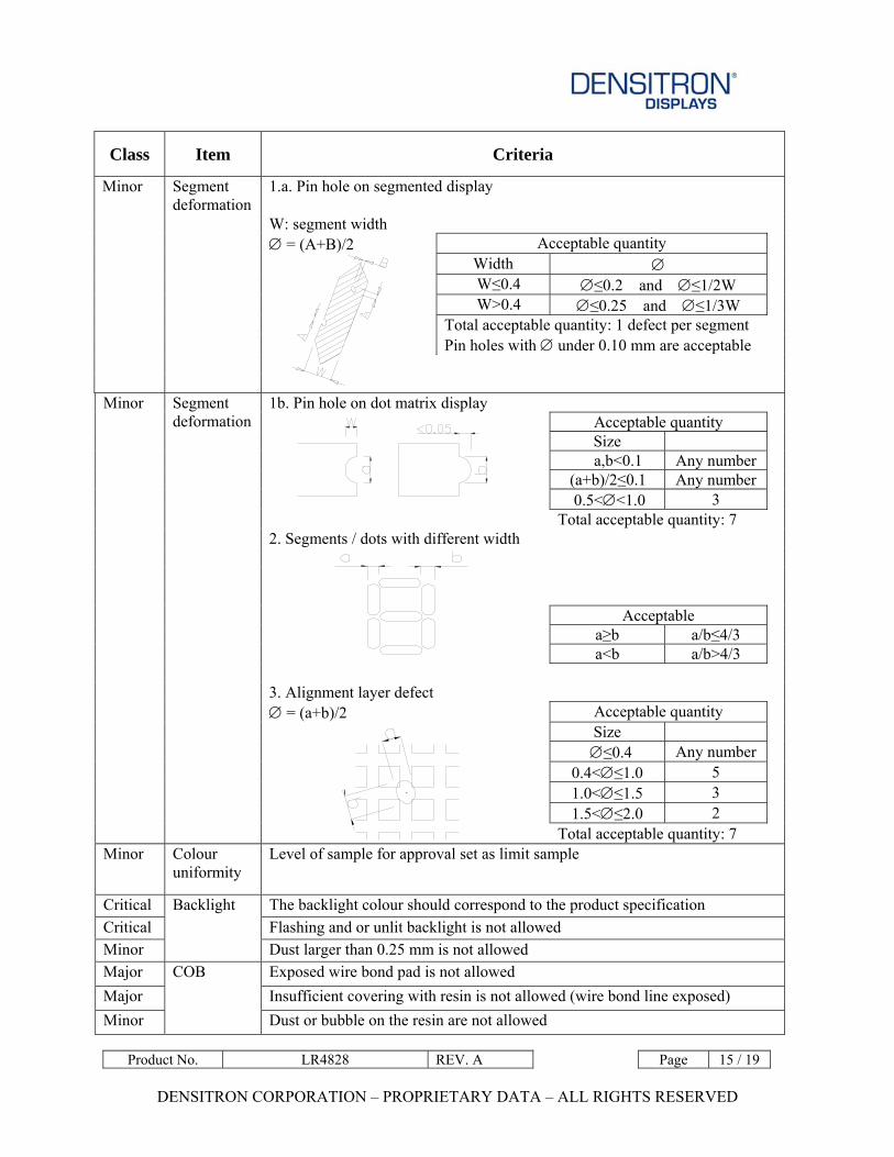
Class Item Criteria
1.a. Pin hole on segmented display W: segment width ∅ = (A+B)/2 Acceptable quantity
Width ∅ W≤0.4 ∅≤0.2 and ∅≤1/2W W>0.4 ∅≤0.25 and ∅≤1/3W Total acceptable quantity: 1 defect per segment Pin holes with ∅ under 0.10 mm are acceptable
Minor Segment deformation
1b. Pin hole on dot matrix display
Acceptable quantity Size
a,b<0.1 Any number (a+b)/2≤0.1 Any number 0.5<∅<1.0 3 Total acceptable quantity: 7
2. Segments / dots with different width
Acceptable a≥b a/b≤4/3
a<b a/b>4/3 3. Alignment layer defect ∅ = (a+b)/2 Acceptable quantity
Size ∅≤0.4 Any number
0.4<∅≤1.0 5 1.0<∅≤1.5 3 1.5<∅≤2.0 2
Minor Segment deformation
Total acceptable quantity: 7 Minor Colour
uniformity Level of sample for approval set as limit sample
Critical The backlight colour should correspond to the product specification Critical Flashing and or unlit backlight is not allowed Minor
Backlight
Dust larger than 0.25 mm is not allowed Major Exposed wire bond pad is not allowed Major Insufficient covering with resin is not allowed (wire bond line exposed) Minor
COB
Dust or bubble on the resin are not allowed

Product No. LR4828 REV. A Page 16 / 19
DENSITRON CORPORATION – PROPRIETARY DATA – ALL RIGHTS RESERVED
Class Item Criteria
Major No unmelted solder paste should be present on PCB Critical Cold solder joints, missing solder connections, or oxidation are not allowed Minor No residue or solder balls on PCB are allowed Critical
PCB
Short circuits on components are not allowed Size Quantity ∅<0.2 Any number On tray
∅>0.25 4 ∅≥0.25 2
On display L = 3 1
Minor Tray particles

Product No. LR4828 REV. A Page 17 / 19
DENSITRON CORPORATION – PROPRIETARY DATA – ALL RIGHTS RESERVED
6 RELIABILITY SPECIFICATION
6.1 RELIABILITY TESTS
Test Item Test Condition Evaluation and assessment
Operation at High Temperature and Humidity 40°C±2°C 90% RH for 240 hours No abnormalities in function*
and appearance**
High Temperature Operation 70°C±2°C for 240 hours No abnormalities in function* and appearance**
Low Temperature Operation -20°C±2°C for 240 hours No abnormalities in function* and appearance**
High Temperature Storage 80°C±2°C for 240 hours No abnormalities in function* and appearance**
Low Temperature Storage -30°C±2°C for 240 hours No abnormalities in function* and appearance**
Heat Shock -30°C (30 min)→ 25°C (5min)→ +80 (30min)→ 25°C (5 min) 10 cycles
No abnormalities in function* and appearance**
Vibration
Sweep for 1 minute at 10Hz, 55Hz, 10Hz, amplitude 1.5mm for 15 minutes in the X, Y and Z directions.
No abnormalities in function* and appearance**
Drop Shock One angle, three edges and six sides. 75cm above ground (no weight difference).
No abnormalities in function* and appearance**
* Current consumption < 2 times initial value ** Contrast > ½ initial value
6.2 LIFE TIME
Item Description
1
Function, performance, appearance, etc. shall be free from remarkable deterioration within 50,000 hours under ordinary operating and storage conditions of room temperature (25±10 °C), normal humidity (45±20% RH), and in area not exposed to direct sunlight.
Product No. LR4828 REV. A Page 18 / 19
DENSITRON CORPORATION – PROPRIETARY DATA – ALL RIGHTS RESERVED
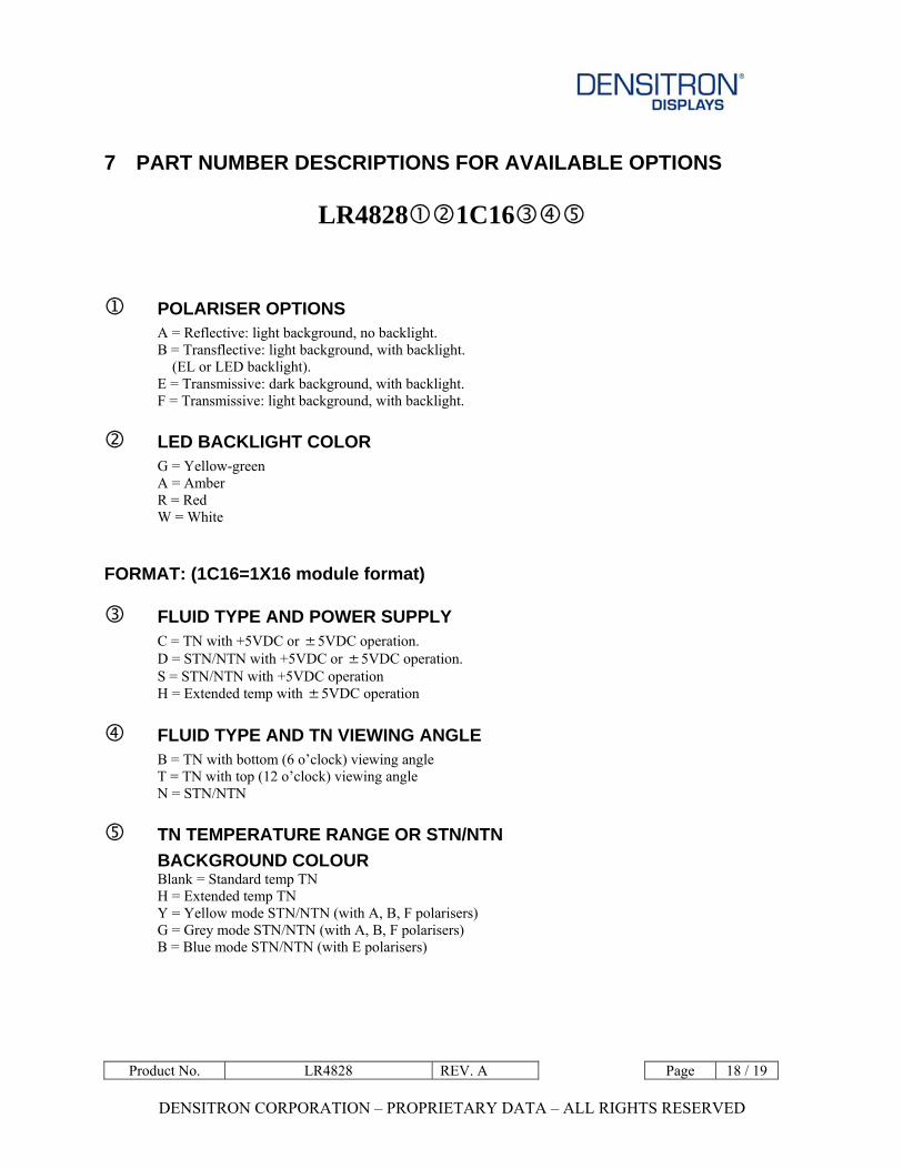
7 PART NUMBER DESCRIPTIONS FOR AVAILABLE OPTIONS
LR4828 1C16
1 POLARISER OPTIONS A = Reflective: light background, no backlight. B = Transflective: light background, with backlight. (EL or LED backlight). E = Transmissive: dark background, with backlight. F = Transmissive: light background, with backlight.
LED BACKLIGHT COLOR G = Yellow-green A = Amber R = Red W = White
FORMAT: (1C16=1X16 module format)
FLUID TYPE AND POWER SUPPLY C = TN with +5VDC or ±5VDC operation. D = STN/NTN with +5VDC or ±5VDC operation. S = STN/NTN with +5VDC operation H = Extended temp with ±5VDC operation
FLUID TYPE AND TN VIEWING ANGLE B = TN with bottom (6 o’clock) viewing angle T = TN with top (12 o’clock) viewing angle N = STN/NTN
TN TEMPERATURE RANGE OR STN/NTN BACKGROUND COLOUR
Blank = Standard temp TN H = Extended temp TN Y = Yellow mode STN/NTN (with A, B, F polarisers) G = Grey mode STN/NTN (with A, B, F polarisers) B = Blue mode STN/NTN (with E polarisers)

Product No. LR4828 REV. A Page 19 / 19
DENSITRON CORPORATION – PROPRIETARY DATA – ALL RIGHTS RESERVED
8 HANDLING PRECAUTIONS Safety If the LCD panel breaks, be careful not to get the liquid crystal fluid in your mouth or in your eyes. If the liquid crystal touches your skin or clothes, wash it off immediately using soap and plenty of water. Mounting and Design Place a transparent plate (e.g. acrylic, polycarbonate or glass) on the display surface to protect the display from external pressure. Leave a small gap between the transparent plate and the display surface. When assembling with a zebra connector, clean the surface of the pads with alcohol and keep the surrounding air very clean. Design the system so that no input signal is given unless the power supply voltage is applied. Caution during LCD cleaning Lightly wipe the display surface with a soft cloth soaked with Isopropyl alcohol, Ethyl alcohol or Trichlorotriflorothane. Do not wipe the display surface with dry or hard materials that will damage the polariser surface. Do not use aromatic solvents (toluene and xylene), or ketonic solvents (ketone and acetone). Caution against static charge As the display uses C-MOS LSI drivers, connect any unused input terminal to VDD or VSS. Do not input any signals before power is turned on. Also, ground your body, work/assembly table and assembly equipment to protect against static electricity. Packaging Displays use LCD elements, and must be treated as such. Avoid strong shock and drop from a height. To prevent displays from degradation, do not operate or store them exposed directly to sunshine or high temperature/humidity. Caution during operation It is indispensable to drive the display within the specified voltage limit since excessive voltage shortens its life. Direct current causes an electrochemical reaction with remarkable deterioration of the display quality. Give careful consideration to prevent direct current during ON/OFF timing and during operation. Response time is extremely delayed at temperatures lower than the operating temperature range while, at high temperatures, displays become dark. However, this phenomenon is reversible and does not mean a malfunction or a display that has been permanently damaged. If the display area is pushed on hard during operation, some graphics will be abnormally displayed but returns to a normal condition after turning off the display once. Even a small amount of condensation on the contact pads (terminals) can cause an electro-chemical reaction which causes missing rows and columns. Give careful attention to avoid condensation. Storage Store the display in a dark place where the temperature is 25°C ± 10°C and the humidity below 50%RH.Store the display in a clean environment, free from dust, organic solvents and corrosive gases. Do not crash, shake or jolt the display (including accessories).