lionel gg1 electric locomotive owner’s manual · lionel gg1 electric locomotive owner’s manual...
TRANSCRIPT

LionelGG1 Electric Locomotive
Owner’s Manual
LionelGG1 Electric Locomotive
Owner’s Manual
71-8354-2503/05
SYSTEM
featuring
and
Do not attempt to raise or lower the pantographs by hand.Be sure that the pantographs have enough clearance on your layout.
Caution!

Congratulations!
Congratulations on your purchase of the Lionel GG1 Electric Locomotive! On the outside, thislocomotive features numerous prototypical details and expert decoration in your favorite
livery. Inside the body, this locomotive is equipped with some of the most advanced sounds andcontrols in model railroading. The Lionel GG1 locomotive is ready for duty on your layout.
Do not attempt to raise or lower the pantographs by hand.
Features of this locomotive
• TrainMaster Command Control equipped—able to run in CommandControl Mode or in Conventional Transformer Control Mode
• Odyssey System for speed control with ON/OFF switch • Refined Conventional Transformer Control Mode with lower starting
speeds and improved Odyssey System controls • Operating pantographs deploy and retract according to direction, a TMCC
CAB-1 command, or with roof-mounted switches • Pantograph lock-down prevents accidental operation on layouts with low
clearances • RailSounds 5.0 sound system with new intelligible CrewTalk dialog and
more TowerCom announcements, each with different scenarios dependingon whether the locomotive is in motion or stopped
• RailSounds 5.0 effects simulate the raising and lowering of thepantographs, perfectly synchronized with each operation
• Independently adjustable volume control—lower the level of backgroundeffects such as the blower with the CAB-1 Remote Controller while keepingoperator-controlled effects such as the horn at full volume
• Dual FatBoy speakers for the ultimate in sound reproduction • Realistic steam generator blow-off—a plume of smoke erupts from the stack • Dual powerful maintenance-free motors with momentum flywheels • Directional LED headlights • Directional marker lights illuminate on the end opposite of the active
headlight • Illuminated number boards • Front and rear ElectroCouplers • Traction tires • Illuminated front cab interior • Minimum Curve: O-72
Caution!
The following Lionel marks may be used throughout this instruction manual and are protected under law.All rights reserved.
Lionel®, TrainMaster®, Odyssey®, RailSounds®, CrewTalk™, TowerCom™, DynaChuff™,StationSounds™, Pullmor®, ElectroCoupler™, Magne-Traction®, CAB-1® Remote Controller,PowerMaster®, Lionel ZW®, ZW®, PowerHouse®, TMCC®, Lionelville™, Lockon®, Wireless Tether™,LionMaster®, FatBoy™
The name FasTrack® is used with permission from Pitsco, Inc.

Table of contents
Quick StartConventional transformer operations 4TrainMaster Command Control operations 4
Conventional transformer operationsConventional operations 5Operating your locomotive in the conventional environment 6Locking your locomotive into a single direction 7Operating your pantographs in the conventional environment 8-9Operating your smoke unit in the conventional environment 9Uncoupling your locomotive in the conventional environment 10
RailSounds 5.0 sound system operationsRailSounds 5.0 sound system operations 11Installing the battery 12Using the RailSounds 5.0 sound system in the conventional environment 13Activating the CrewTalk dialog and TowerCom announcements
in the conventional environment 14Installing a Lionel Sound Activation Button for conventional operation 15Using the RailSounds 5.0 sound system in the TrainMaster Command Control environment 16Activating the CrewTalk dialog and TowerCom announcements
in the Command Control environment 17RailSounds 5.0 sound system dialog on a round trip 18
Odyssey System operationsOdyssey System operations 19Odyssey System conventional (transformer) operation 19Odyssey System Command Control operation 20
TrainMaster Command Control operationsTrainMaster Command Control operations 21Operating your locomotive in the Command Control environment 21CAB-1 Remote Controller commands 22CAB-1 Remote Controller numeric keypad commands 23CAB-1 numeric keypad table 24Operating the pantographs in the Command Control environment 25-26Operating the smoke unit in the Command Control environment 26Tuning your locomotive’s performance 27-28Assigning your locomotive a new ID# 29Building a lash-up 30Reprogramming your locomotive to restore features 31
Maintaining and servicing your locomotiveAdding fluid to your locomotive’s smoke generator 32Lubricating your locomotive 33-34Servicing your locomotive’s LEDs and lamps 35Servicing the traction tires 35Servicing the pantographs 35Limited Warranty/Lionel Service 363

Quick StartConventional transformer operations
Do not attempt to raise or lower the pantographs by hand.
Be sure to remove the paper bands from around the pantographs before you operatethe locomotive.
1. Place your locomotive on Lionel or Lionel-compatible O-72 or largertrack.
2. Power your locomotive at 8-19 volts with your alternating current (AC)transformer.
Do not power your locomotive with a direct-current (DC) transformer. Damage tosensitive electronic components may occur.
3. Wait three to eight seconds as your locomotive determines whether it is ina conventional environment or a TrainMaster Command Controlenvironment. The pantographs will operate automatically.
4. Move ‘em out! Press the DIRECTION button on your controller, thenthrottle up.
TrainMaster Command Control operations
Do not attempt to raise or lower the pantographs by hand.
Be sure to remove the paper bands from around the pantographs before you operatethe locomotive.
To operate your locomotive in the Command Control environment, you need a CommandBase (available separately, 6-12911) and a CAB-1 Remote Controller (available separately,
6-12868). These products are available together in the TrainMaster Command Set (6-12969).
1. Turn off track power and plug in the Command Base.
2. Place your locomotive on Lionel or Lionel-compatible O-72 or largertrack.
3. Increase track voltage to full power or 19 volts AC.
Do not power your locomotive with a direct-current (DC) transformer. Damage tosensitive electronic components may occur.
4. Press ENG and 1 to address your locomotive with your CAB-1 RemoteController. The pantographs will operate automatically.
5. Throttle up and move ‘em out.
4
Note!
Note!
Note!
Note!
Caution!
Caution!

Conventional transformer operationsConventional operations
Your locomotive is capable of operating in the conventional environment with nothing morethan a standard Lionel alternating-current (AC) transformer.
In the conventional environment, your locomotive cycles through a repeating pattern ofoperations: forward, neutral, reverse, neutral, and so on. To advance to the next operation, pressthe DIRECTION button on your transformer. Alternately, you could use the throttle to brieflyturn off track power so that the locomotive advances to the next operation when power isrestored.
Once you cycle the locomotive into forward or reverse, you control your locomotive’s speedby varying track voltage with the transformer’s throttle. To increase the speed of the locomotive,you increase track voltage. To decrease the speed, you decrease track voltage. To stop thelocomotive and to change directions (or to enter neutral), track voltage is turned off orinterrupted.
Use the HORN and BELL buttons on your transformer (or separate buttons if yourtransformer is not equipped with these controls, see page 15) to activate these features.
To experience all of your locomotive’s features, we recommend operating in the TrainMasterCommand Control environment. With a simple one-wire connection, you can use the CAB-1Remote Controller to access all of the functions of your locomotive. Refer to pages 21-31 to seehow to operate your locomotive in the TrainMaster Command Control environment.
5

Conventional transformer operationsOperating your locomotive in the conventional environment
Do not attempt to raise or lower the pantographs by hand.
Be sure to remove the paper bands from around the pantographs before you operatethe locomotive.
1. Place your locomotive on Lionel or Lionel-compatible O-72 or largertrack.
2. Power your locomotive at 8-19 volts with your alternating current (AC)transformer.
Power your locomotive with an alternating-current (AC) transformer only.Powering your locomotive with a direct-current (DC) transformer may result indamage to sensitive electronic components.
3. Wait three to eight seconds as your locomotive determines whether it is ina conventional environment or a TrainMaster Command Controlenvironment. The pantographs will operate automatically.When the locomotive has determined that a TrainMaster Command Base is not connected tothe track, the locomotive’s headlight will illuminate and the RailSounds sound system willstart. You are ready for operation in the conventional environment.
4. Move ‘em out!Press the DIRECTION button on your transformer to sequence your locomotive throughthe repeating pattern of operations: forward, neutral, reverse, neutral, and so on. You mayalso briefly turn off track power to advance the locomotive to the next operating state. Adjustthe throttle until your locomotive moves at your desired speed.
When placing your locomotive on your layout for the first time, it will start out inneutral. The RailSounds sound system will be silent, except for the pantographsounds. Thereafter, it will start in forward after every power interruption lasting fiveseconds or longer.
Use the HORN and BELL buttons on your transformer to activate those features. Refer topage 15 if your transformer is not equipped with those buttons. Adjust the volume using thevolume control knob located under the removable roof-top hatch. Refer to Figure 1 on page 7.
6
Note!
Caution!
Caution!
Note!

Conventional transformer operationsLocking your locomotive into a single direction
When the Command reverse unit switch is in the RUN position, your locomotive sequencesthrough a repeating pattern of operations: forward, neutral, reverse, neutral, and so on.
To “lock” your locomotive into a single direction (for example, to operate in forward only),you can deactivate the Command reverse unit’s sequencing function. Refer to Figure 1 for thelocation of the Command reverse unit switch.
1. Use your transformer’s DIRECTION button or interruptions in track power to get yourlocomotive moving in the desired direction or into neutral.
2. Slow the locomotive down without stopping (reduce the throttle without turning off trackpower).
3. Slide the Command reverse unit switch to the PROG position. At this point, the locomotive is“locked” into your chosen direction.
To restore the forward-neutral-reverse sequence, turn off track power and slide theCommand reverse unit switch back to the RUN position.
7Figure 1. Switch locations
PENTARUN ↔ DOWN
SIGNALSOUND ↔ RAILSOUND
COMMAND REVERSEPROG ↔ RUN
PANTARUN ↔ LOCK
SMOKEOFF ↔ ON
ODYSSEYOFF ↔ ON
FRONT
PANTARUN ↔ DOWN
SIGNALSOUND ↔ RAILSOUND
COMMAND REVERSEPROG ↔ RUN
PANTARUN ↔ LOCK
SMOKEOFF ↔ ON
ODYSSEYOFF ↔ ON
Volumecontrolknob

Conventional transformer operationsOperating your pantographs in the conventional environment
To prevent damage to your locomotive, do not raise or lower the pantographs byhand. Be sure that the pantographs have enough clearance on your layout.
Be sure to remove the paper bands from around the pantographs before you operatethe locomotive.
Your GG1 locomotive is equipped with two operating pantographs. Do not raise or lower thepantographs by hand, or you will damage the locomotive. Be sure that the pantographs
clear all bridges, signals, and other objects on your layout. Refer to Figure 2 to determine theproper clearance.
The operation of the pantographs corresponds with the direction of travel. When thelocomotive is in neutral, both pantographs are raised. If the locomotive travels forward, only therear pantograph is raised. If the locomotive travels backward, only the front pantograph israised. After a direction change, the lowered pantograph raises, and then thereis a ten-second delay before the pantographs change positions.
Caution!
8
6.25"
3"
Figure 2. Locomotive clearance
Note!

Conventional transformer operationsOperating your pantographs in the conventional environment(continued)
Locking down the pantographs in the conventional environment
If you have bridges, signals, or other trackside structures with low clearance, you will needto lock down the pantographs. Follow these steps to lock both pantographs in the loweredposition.
1. Turn off track power.
You must turn off track power before sliding the RUN/DOWN switch to the DOWNposition.
2. With track power off, slide the RUN/DOWN switch to the DOWN position.
3. Be sure that the RUN/LOCKOUT switch is in the RUN position.
4. Power up the track. Both pantographs will lower. Cycle the locomotive into neutral, then slide the RUN/DOWN switch to the RUN position toresume automatic operation of the pantographs.
Locking the pantographs in your desired position
To lock the pantographs in any position (both up, both down, one up, one down, etc.),simply operate the locomotive until the pantographs are in your desired position and slide theRUN/LOCKOUT switch to the LOCKOUT position. Your locomotive will now operate with thepantographs in your desired position. When you are ready to resume normal operations, cyclethe locomotive into neutral, then slide the switch back to the RUN position.
Operating the smoke unit in the conventional environment
Your locomotive is equipped with a smoke unit to simulate the operation of the steamgenerator. When the smoke unit switch is in the ON position, always be sure that there is a
small amount of smoke fluid in the smoke generator. To turn off the smoke unit, slide thesmoke unit switch to the OFF position. See Figure 1 on page 7 for the switch locations.
When you first power up your locomotive, the smoke unit requires approximately 30 secondsto warm up. The smoke unit will automatically turn on for five seconds. The smoke unit willalso turn on for five seconds after every five minutes of continuous operation in a singleoperational state (in forward, reverse, or neutral and after changes in direction) and afterchanges in direction. Be sure to install a nine-volt battery for the smoke unit tooperate while the locomotive is in neutral. See page 12.
Always be sure that there is smoke fluid in the smoke unit when the smoke unitswitch is in the ON position. When smoke production decreases, add more smokefluid as discussed on page 32.
9
Caution!
Note!

Conventional transformer operationsUncoupling your locomotive in the conventional environment
Your locomotive features two ElectroCouplers that are released by remote control at anypoint around your layout in the TrainMaster Command Control environment.
In the conventional environment, the ElectroCouplers will not open manually or by using aRemote-Control Track section. To couple your locomotive in the conventional environment, youmust rely on a piece of rolling stock equipped with a magnetic coupler. Simply release themagnetic coupler and couple the rolling stock to the locomotive, even if the ElectroCoupler isclosed.
Keep in mind that you may still make use of Lionel Remote-Control Track sections (6-65530for O gauge; 6-12746 and 6-65149 for O-27 gauge; and 6-12020 for FasTrack layouts) with themagnetic couplers on the rolling stock. Place the trigger disc on the magnetic coupler over thecentral coil on the Remote-Control Track section, then press UNCOUPLE on the track section’scontroller. As illustrated in Figure 3, the magnetic field pulls the disc downward, releasing thecoupler.
10
Figure 3. Magnetic coupler operation
Remote-ControlTrack Section

11
RailSounds 5.0 sound system operationsRailSounds sound system operations
Your locomotive is equipped with the Lionel RailSounds 5.0 sound system, the most realisticmodel railroad sound system in the world. The RailSounds sound system brings the sounds
of the railroad to your layout through high quality sound recordings of real locomotives. When you operate your locomotive in the conventional environment, you get the realistic
sounds of the electric motor, which automatically rev up as the speed of the locomotiveincreases. You can sound the locomotive’s horn or activate the ringing of the mechanical bell.CrewTalk dialog and TowerCom announcements are triggered with the horn button on yourcontroller. When you are through with operations and power down the track, your locomotive’sRailSounds sound system starts a realistic shutdown sequence (a nine-volt alkaline battery isrequired, see page 12).
When you operate your locomotive in the TrainMaster Command Control environment, youget full control of the RailSounds 5.0 sound system. In addition to the horn and bell sounds, thelocomotive’s RPM sounds automatically rev up, and you can also set a particular RPM levelusing your CAB-1 Remote Controller. In the Command Control environment, the release of theElectroCouplers is accompanied by a coupler release sound. Use the BRAKE button, and listenfor the sound of squealing metal. You can also trigger CrewTalk dialog and TowerComannouncements, which simulate the interaction between the locomotive crew and thedispatcher. Whenever you choose to shutdown your locomotive, the realistic shutdown sequencecommences (a nine-volt alkaline battery is required if track power is turned off, see page 12).

RailSounds 5.0 sound system operationsInstalling the battery
Although the RailSounds sound system is powered through the track, we recommend thatyou install a nine-volt alkaline battery to prevent the sound system from shutting down
during track power interruptions (for example, at a switch or a dirty section of track). Followthese steps and refer to Figure 4 as you install the battery.
If the RailSounds sound system turns off during interruptions in track power, youmay need to replace the battery.
1. Lift away the rear removable roof-top hatch.
2. Remove the protective cover from the battery harness.
3. Snap the battery harness onto the nine-volt alkaline battery’s terminals.
4. Slide the battery into the battery clip.
5. Replace the hatch. Two magnets secure the hatch to the roof.
The roof hatches serve as your locomotive’s antenna. Be sure that the hatches are inplace before operating your locomotive in the TrainMaster Command Controlenvironment.
12
Rear roof-top hatch (TMCC antenna)
Note!
Battery harness
Battery holder
Figure 4. Battery installation
Note!
REAR
FRONT

RailSounds 5.0 sound system operationsUsing the RailSounds 5.0 sound system in the conventional environment
When you first power up your locomotive, you will hear the sounds of the operatingpantographs and the locomotive at rest. As the locomotive moves, the RPM sounds
automatically increase with the locomotive’s speed. In the conventional environment, the hornand bell sounds are activated by your transformer controls.
To silence the motor sounds, slide the RailSounds 5.0 sound system switch located on theunder the front roof-top hatch to the SIGNALSOUNDS position before you power up thelocomotive or after the locomotive has been powered down for a minimum of ten seconds. Thehorn and bell sounds will still be active. To adjust the volume, use the volume control knoblocated beneath the front roof-top hatch. Refer to Figure 1 on page 7.
For proper operation of the RailSounds 5.0 sound system during track powerinterruptions and for the locomotive shutdown sequence, you must install a nine-voltalkaline battery. See page 12.
In the conventional environment, you will experience several features of the RailSounds 5.0sound system.
• Eight levels of electric motor RPM. The level of electric motor RPM automaticallyvaries with your throttle adjustments.
• MultiHorn. A different horn sound at different speeds—a RailSounds sound systemexclusive.
• Mechanical bell. Press BELL on your transformer to begin the effect, then press BELL asecond time to discontinue the effect.
• CrewTalk dialog and TowerCom announcements. CrewTalk dialog is triggered byyour transformer’s HORN button.
• Reverse unit reset sound. Power down your track, wait three seconds, and listen forthe air-release sound—that’s the locomotive telling you that its Lionel Command reverseunit has reset to forward.
• Shutdown sequence. When you turn off track power, you have two seconds to power upagain after you hear the reverse unit reset sound. If you do not restore power, you will hearthe realistic electric shutdown sequence. Because track power is off, a nine-volt battery isrequired for this sequence to function.
• Pantograph sounds. Listen for the sounds of the spring-pneumatic equipment thatraises and lowers the pantographs.
• Steam generator blow-off sound. Listen for the blow-off sound of the steamgenerator when the smoke unit turns on.
13
Note!

Activating the CrewTalk dialog and TowerCom announcements inthe conventional environment
In the conventional environment, CrewTalk dialog and TowerCom announcements aretriggered by short horn blasts and vary with the state of the locomotive.
• If the locomotive has been stopped for less than 15 seconds, a short horn blast triggers a“please standby” dialog.
• If the locomotive has been stopped for longer than 15 seconds, a short horn blast triggers a“cleared outbound” dialog.
• If the locomotive is moving, a short horn blast triggers an “all clear ahead” dialog.• If the locomotive is moving with the bell activated, a short horn blast triggers a “slow to
caution” dialog.
RailSounds 5.0 sound system operations
14

RailSounds 5.0 sound system operationsInstalling a Lionel Sound Activation Button for conventional operation
If your transformer lacks HORN and BELL buttons, you will need to install Lionel no. 610-5906-001 Sound Activation Buttons (available separately) to activate the locomotive’s
horn and bell sounds.Connect the buttons as shown below. Be sure that all track power passes through the Sound
Activation Button(s). Do not bypass the buttons.
15
1 2
POWERSUPPLY
POWERSUPPLY
For AC transformers lacking a bell button
For AC transformers lacking bell and horn/whistle buttons
Existing wireBlack wire
Red wire
Lionel no. 610-5906-001Sound Activation Button for activating the bell
Lionel no. 610-5906-001Sound Activation Buttonfor activating the horn
Lionel no. 610-5906-001Sound Activation Button for activating the bell
Black wire
Black wire
Wirenut
Red wire
Red wireExisting wire
Common/Ground/U
Power/A
Common/Ground/U
Power/A

16
RailSounds 5.0 sound system operationsUsing the RailSounds 5.0 sound system in the TrainMaster CommandControl environment
To access all of the features of the RailSounds 5.0 sound system, you must operate yourlocomotive in the TrainMaster Command Control environment. The CAB-1 Remote Controller
is required to activate features such as TowerCom announcements, CrewTalk communication, andcoupler release sounds. Refer to pages 21-31 to learn how the RailSounds 5.0 sound system isintegrated into TrainMaster Command Control operations.
For proper operation of the RailSounds sound system during track powerinterruptions and for the locomotive shutdown sequence, you must install a nine-voltalkaline battery. See page 12.
In the TrainMaster Command Control environment, you will experience all of the features ofthe RailSounds sound system.
• Eight levels of electric motor RPM. Your CAB-1 Remote Controller throttleautomatically determines the level of the electric motor RPM. You may also set the RPMsounds to a particular level manually using your CAB-1 Remote Controller.
• MultiHorn. A different horn sound at different speeds—a RailSounds 5.0 sound systemexclusive.
• Mechanical bell. Press BELL on your CAB-1 Remote Controller to begin the effect, thenpress BELL a second time to discontinue the effect.
• Squealing brakes. Press the BRAKE button and listen for the squealing of thelocomotive’s brakes as the locomotive slows down.
• Coupler release sounds. Use your CAB-1 Remote Controller to release anElectroCoupler, and you get the sounds of the coupler opening.
• CrewTalk dialog and TowerCom announcements. Use your CAB-1 Remote Controllerto trigger conversations between the dispatcher and locomotive engineer. You’ll hear “hold forclearance,” “cleared for departure,” and many other exchanges. See pages 17 and 18.
• Shutdown sequence. When you turn off track power, you have two seconds to power upagain after you hear the reverse unit reset sound. If you do not restore power, you will hearthe realistic electric shutdown sequence. Because track power is off, a nine-volt battery isrequired for this sequence to function. You may also trigger the shutdown sequence usingAUX1, 5 command without powering down the track.
• Pantograph sounds. Listen for the sounds of the spring-pneumatic equipment thatraises and lowers the pantographs.
• Steam generator blow-off sound. Listen for the blow-off sound of the steamgenerator when the smoke unit turns on.
Note!

Activating the CrewTalk dialog and TowerCom announcements inthe Command Control environment
With the RailSounds 5.0 sound system, CrewTalk dialog and TowerCom announcementsfeature a variety of brief radio conversations between the engineer and dispatcher. All
dialog is intelligible, and each comment is followed by at least one automatic response.CrewTalk dialog is an engineer-initiated radio conversation with the dispatcher. TowerCom
announcements are a dispatcher-initiated radio conversation with the engineer. Be sure to listenfor the different combinations of words and phrases that comprise these exchanges.
Refer to Table 1 below for the dialog commands. The dialog in the table provides examples ofthe conversations you can trigger. The actual dialog will vary.
Locomotive Commands Example dialog
AUX1, 2 Crew: Can we go?Tower: No, please standby
AUX1, 7 Tower: Stand by for clearance.Crew: Roger.
Stopped 2 Crew: Can we go?Tower: Roger, you are clear.
7 Tower: You are clear for departure.Crew: Roger, we are clear.
AUX1, 5 Crew: Signing off!Shutdown sequence
AUX1, 2* Crew: Train is arriving.Tower: Roger, you are clear inbound.
AUX1, 7* Tower: You are clear for arrival.Crew: Roger.
Moving 2 Crew: Are we clear ahead?Tower: You are all clear.
7 Tower: You are all clear.Crew: Roger.
AUX1, 5 Tower: Come to an immediate stop.Crew: We are stopping now.
5 Tower: Slow to caution speed.Crew: Roger, slowing now.
* Activating either AUX1, 2 or AUX1, 7 while the locomotive is in motion enables a “train has nowarrived” conversation for 15 seconds. If the train stops within this time, pressing 2 or 7 will play thisspecial conversation.
Table 1. CAB-1 Remote Controller dialog commands
17
RailSounds 5.0 sound system operations

18
RailSounds 5.0 sound system operationsRailSounds 5.0 sound system dialog on a round trip
Figure 5. RailSounds 5.0 sound system dialog on a round trip
Refer to Figure 5 for a sample dialog script for the locomotive’s round trip.
AUX1, 7 - “Stand by.”7 - “You are clear.”
5 - “Slow to caution speed.”AUX1, 5 - “Come to a full stop.”
7 - “Welcome back, stand by.” 7 - “All clear ahead.”AUX1, 7 - “You are clear inbound.”
AUX1, 2 - “Are we clear?”/” No, stand by.”2 - “Can we go yet?”/”Yes, you are clear.”
2 - “Still clear ahead?”/“Roger, you are clear.”
7 - “we have arrived and we are standing by.”
AUX1, 2 - “We are arriving,”/“OK, you are clear inbound.”
ENGINEER-INITIATED DIALOG
TOWER-INITIATED DIALOG

19
The Odyssey System is automatically active when you operate your locomotive inconventional (non-Command Control) mode, as long as the Odyssey switch is in the ON
position (see Figure 1 on page 7). This means that your locomotive will maintain a constantspeed, compensating for grades, loads, and turns. Simply use your transformer’s throttle toadjust the speed of your locomotive. If you would like to deactivate the speed control feature,slide the Odyssey switch to the OFF position while the locomotive is not in motion.
In conventional operation, the lights in the locomotive are connected directly totrack power. Do not exceed 16 volts for extended periods. Doing so will reduce thelife of your lamps.
Because of the way that speed control operates in conventional mode, you will noticea slight delay between adjusting your transformer throttle and the change in thespeed of your locomotive. If you desire instantaneous response to throttle changes,turn off the Odyssey System.
Odyssey System operations
Odyssey System conventional (transformer) operation
The Odyssey System
The Odyssey System is “cruise control” for your locomotive. Once the speed is set (see below),your locomotive will maintain a constant speed, no matter what loads the locomotive pulls
or what grades you have on your layout. This digitally-controlled system also allows forextremely slow movement that will amaze any “scale” enthusiast.
Caution!
Note!

20
Odyssey System operationsOdyssey System Command Control operation
When the Odyssey System is activated, changes in the speed of the locomotive willcorrespond to each signal from the Command Base. For example, when you address the
locomotive and slowly turn the throttle knob, the first flash of the light on the Command Basecorresponds to the first speed step, which is the slowest speed of the locomotive. The locomotivewill maintain that speed until you increase or decrease the throttle.
In the TrainMaster Command Control environment, you can use your CAB-1 RemoteController to turn the Odyssey System on or off. The position of the Odyssey System switch (seeFigure 1 on page 7) is the Odyssey System default setting when you power up the locomotive.You can override the default setting with the following commands. The override settings will becleared and the default setting will be restored when you power down the locomotive.
Do not wait longer than two or three seconds between pushing the buttons in each sequence.If the command is not accepted, repeat the sequence.
The locomotive must be in “neutral” when you enable or disable the Odyssey System.
Turn off the Odyssey System.
When you press 7, you will trigger a TowerCom announcement. This has no impacton the Odyssey System function.
Turn on the Odyssey System.
When you press 9, you will activate the Air release sound and turn on the smoke unitfor five seconds of operation if the smoke unit switch is in the ON position. This hasno impact on the Odyssey System.
Note!
Note!
Note!

TrainMaster Command Control operationsTrainMaster Command Control operations
TrainMaster Command Control is the advanced model railroad control system from Lionel. Tooperate your locomotive in the Command Control environment, you need a Command Base
(available separately, 6-12911) and a CAB-1 Remote Controller (available separately, 6-12868). Your commands are sent by the CAB-1 Remote Controller to the Command Base, which then
translates the command into digital code. That code is sent through the outside rails to yourlocomotive, which will not respond until it recognizes its unique ID#. TrainMaster CommandControl gives you the power to operate multiple Command-equipped locomotives on the sametrack at the same time.
Keep in mind that track power is like gasoline in the tank of a car—it gives you the powerto go places, but it doesn’t tell you where to go or how fast to get there.
Operating your locomotive in the Command Control environment
Be sure to remove the paper bands from around the pantographs before you operatethe locomotive.
1. Turn off track power and plug-in the Command Base. Be sure that theCommand Base is connected to the outside rail or to the Common/Ground/U terminal onyour track power supply.
2. Place your locomotive on Lionel or Lionel-compatible O-72 or largertrack.
3. Increase track voltage to full power or 19 volts AC. On PowerMasters, slide theCMD/CONV switch to CMD. Program Track Power Controllers to Command Controloperation.
4. Press ENG, enter the ID#, and press AUX1 for the prototypical pantographstart-up sequence with pantograph sounds followed by the full RailSounds soundsystem start-up. For immediate RailSounds sound system start-up, press ENG, enter the ID#,and press any button, except AUX1. All Lionel locomotives come factory-programmed asID# 1. To change the ID#, see page 29.
5. Throttle up and move ‘em out! Your locomotive will respond to every command fromyour CAB-1 Remote Controller.
21
Note!

TrainMaster Command Control operationsCAB-1 Remote Controller commands
The CAB-1 Remote Controller commands are detailed below. The correspondingRailSounds sound system effects are in bold italic type.
Releases the front coupler. Coupler release sound.
Releases the rear coupler. Coupler release sound.
Activates the numeric keypad. Air release sound.
Toggles the headlights and marker lights on and off.
Accelerates the locomotive with a clockwiserotation. Decelerates the locomotive with a
counter-clockwise rotation.
Shuts off track power and stops all TrainMasterCommand Control and conventional
locomotives. Use HALT only in emergency situations.
Activates the locomotive’s horn. Release thebutton to discontinue the sound. Multihorn
air horn sound.
Toggles the bell sound on and off. Mechanicalbell sound.
Changes the locomotive’s direction. Thelocomotive decelerates to a stop and continues in
the opposite direction when you increase the throttle.The pantographs change position. Air release sound.Pantograph sounds (if the pantographs are not lockeddown).
Increases the locomotive’s speed while the button is pressed. Release the button to return to the initial speed.
Decreases the locomotive’s speed while the button is pressed. Squealing brake sounds.
22
SET L M H
See page 27 to change themomentum settings.

TrainMaster Command Control operationsCAB-1 Remote Controller numeric keypad commands
When you press the AUX1 button on your CAB-1 Remote Controller, you turn the numerickeypad into ten command buttons. These commands are specific to your locomotive, and
an overlay is included to help you learn these functions. After you press the AUX1 button, youwill be able to press any numbered button until you address a different Command Controlequipped product. The corresponding RailSounds sound system effects are inbold italic type.
Stops and resets the locomotive. Resets the locomotive’s direction to forward. Resets thepantograph operation with the full start-up sequence. Horn blows. RPM soundsreturn to automatic.
Raises the volume of the RailSounds sound system background sounds, such as RPMsounds and let-off sounds. The horn, bell and dialog are unaffected. The default is fullvolume. The volume setting is retained when track power is turned off. Sound volumeincreases.
Engineer begins radio dialog, dispatcher replies (see pages 17 and 18). CrewTalkcommunication.
Enters manual RPM mode and increases the RailSounds sound system RPM level (see page 27). If the RailSounds sound system is shut down (see 5 key below), AUX1, 3activates a full RailSounds sound system start-up with prototypical pantograph operationwhile the locomotive is stopped after pressing AUX1, 5 with track power on.
Lowers the volume of the RailSounds sound system background sounds, such as RPMsounds and let-off sounds. The horn, bell, and dialog are unaffected. The volume setting isretained when track power is turned off. Sound volume decreases.
Activates the RailSounds sound system shutdown sequence. Optionally lowers thepantographs (see page 24).
Enters manual RPM mode and lowers the RailSounds electric motor RPM level (see page 27).Optionally cycles the pantographs through all position combinations (see page 24).
Dispatcher begins radio dialog, engineer replies (see pages 17 and 18). TowerComannouncement.
Turns off the smoke unit. Air release sound.
Turns on the smoke unit if the smoke unit switch is in the ON position. Press 9 to activate thesmoke unit for five seconds. Press and hold 9 for continuous operation of the smoke unit. Besure to add smoke fluid before turning on the smoke unit to prevent damage to your locomotive.Steam generator blow-off sound.
AUX1, 8 and 9 function only if the locomotive’s smoke unit switch is in the ON position.Sounds will be active in both switch positions.
23
Note!

CAB-1 numeric keypad table
The 3, 5, and 6 keys on your CAB-1 can perform several different functions when controllingyour GG1. These functions include:
• Starting up and shutting down the engine sounds, with or without activating thepantograph.
• Controlling the engine RPM sounds manually ("Manual RPM Mode").
• Controlling the pantograph positions manually ("Manual Pantograph Mode").
If you press AUX1 immediately before you press the 3, 5 or 6 button, its function will bemodified. The following table summarizes the functions of these CAB-1 Remote Controllerbuttons for your GG1.
Key Command Pantograph (active only RailSounds sound systemif locomotive is stopped)
3 No effect If the RailSounds sound system is shut down,engine sounds start up. If the RailSounds sound system is running, engine enters manual RPM mode and revs up RPM one level.
AUX1, 3 Pantographs move to (same as above)prototypical position.
5 No effect If locomotive is stopped, engineer announces"shut down," engine sounds turn off. (If thelocomotive is moving, see page 17.)
AUX1, 5 Pantographs move to "down" (same as above)position.
6 If the locomotive is stopped, If the locomotive is moving, engine enterscycle pantographs to next manual RPM mode and revs down RPMposition if pantograph manual one level.mode is active, otherwise no effect. (See page 25.)
AUX1, 6 Pantographs enter manual (same as above)mode and cycle through positions (See page 25.)
24
TrainMaster Command Control operations

TrainMaster Command Control operationsOperating the pantographs in the Command Control environment
To prevent damage to your locomotive, do not raise or lower the pantographs byhand.
Be sure to remove the paper bands from around the pantographs before you operatethe locomotive.
Your GG1 locomotive is equipped with two operating pantographs. Do not raise or lower thepantographs by hand or you will damage the locomotive. Be sure that the pantographs
clear all bridges, signals, and other objects on your layout. Refer to Figure 2 on page 8 todetermine the proper clearance.
Normally, the operation of the pantographs is prototypical and automatically correspondswith the direction of travel. If the locomotive travels forward, only the rear pantograph is raised.If the locomotive travels backward, only the front pantograph is raised.
You may also override this automatic operation and control the position of the pantographsmanually, as described below.
Manual Control of Pantographs
The pantographs on your GG1 may be controlled manually using the 6 button on your CAB-1Remote Controller. Using this function you may cycle your GG1's pantographs through all fourcombinations of UP and DOWN positions.
To start manual control of the pantographs, press AUX1, 6 while your locomotive is stopped.Both pantographs will move to the UP position. If you press 6 again after a minimum of threeseconds but within ten seconds, the pantographs will cycle to the next position. If you wait more thanten seconds, the 6 button will no longer cycle the pantographs (this allows you to use the 6 button tocontrol the engine RPMs manually - see page 27). If you wish to resume manual control of thepantographs, simply press AUX1, 6 again and the pantographs will cycle to their next position.
Note that you may not change the position of the pantographs while the locomotive in inmotion.
Also note that once you start to control the pantographs manually, the normal automaticoperation is suppressed and changing your locomotive's direction will not change thepantograph position. To resume normal automatic operation, press AUX1, 0 to reset the engine.
Locking down the pantographs
You must turn off track power before sliding the RUN/DOWN switch to the DOWN orRUN position.
If you have bridges, signals, or other trackside structures with low clearance, you will need tolock down the pantographs. To lock the pantographs in the down position, turn off track power,then slide the RUN/DOWN switch to the DOWN position. To resume normal operation, turntrack power off, then slide the switch back to the RUN position.
25
Note!
Note!
Caution!
TrainMaster Command Control operationsOperating the pantographs in the Command Control environment(continued)
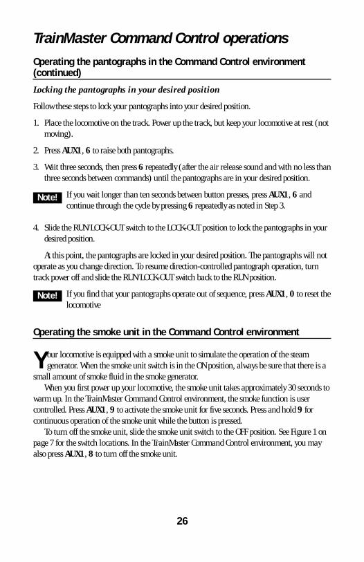
Locking the pantographs in your desired position
Follow these steps to lock your pantographs into your desired position.
1. Place the locomotive on the track. Power up the track, but keep your locomotive at rest (notmoving).
2. Press AUX1, 6 to raise both pantographs.
3. Wait three seconds, then press 6 repeatedly (after the air release sound and with no less thanthree seconds between commands) until the pantographs are in your desired position.
If you wait longer than ten seconds between button presses, press AUX1, 6 andcontinue through the cycle by pressing 6 repeatedly as noted in Step 3.
4. Slide the RUN/LOCK-OUT switch to the LOCK-OUT position to lock the pantographs in yourdesired position.
At this point, the pantographs are locked in your desired position. The pantographs will notoperate as you change direction. To resume direction-controlled pantograph operation, turntrack power off and slide the RUN/LOCK-OUT switch back to the RUN position.
If you find that your pantographs operate out of sequence, press AUX1, 0 to reset thelocomotive
Operating the smoke unit in the Command Control environment
Your locomotive is equipped with a smoke unit to simulate the operation of the steamgenerator. When the smoke unit switch is in the ON position, always be sure that there is a
small amount of smoke fluid in the smoke generator. When you first power up your locomotive, the smoke unit takes approximately 30 seconds to
warm up. In the TrainMaster Command Control environment, the smoke function is usercontrolled. Press AUX1, 9 to activate the smoke unit for five seconds. Press and hold 9 forcontinuous operation of the smoke unit while the button is pressed.
To turn off the smoke unit, slide the smoke unit switch to the OFF position. See Figure 1 onpage 7 for the switch locations. In the TrainMaster Command Control environment, you mayalso press AUX1, 8 to turn off the smoke unit.
26
Note!
Note!

TrainMaster Command Control operationsTuning your locomotive’s performance
TrainMaster Command Control allows you to fine-tune the performance of your locomotive.Use your CAB-1 Remote Controller to make these adjustments.
These settings will be lost if you assign a new ID#.
RPM LEVELYour locomotive’s RPM level varies with the CAB-1 Remote Controller throttle in automatic
RPM mode. You may choose to set a constant, or fixed, RPM level in manual RPM mode.
Automatic RPM modeThe intensity of the RPM sounds will vary with adjustments to the throttle. When you stop
the locomotive for two seconds or more, the RPM sounds will return to their initial intensity.This is the locomotive’s default setting.
Manual RPM modeManual RPM mode allows you to set a constant RPM level for your locomotive. In this
setting, the RPM level will not vary with the throttle settings or the speed of the locomotive.To set a constant RPM level, get your locomotive moving, then press AUX1, 3 or AUX1, 6
to enter manual RPM mode. The locomotive will be locked at the current RPM level. To adjustthe RPM level, press 3 to ramp up or 6 to ramp down. The locomotive will retain this setting.
When the locomotive is in motion, you may adjust the RPM level. To adjust the RPM levelafter ten seconds have elapsed, simply press AUX1, 3 or AUX1, 6 again. To exit manual RPMmode, turn off track power and allow the locomotive to reset, enter the shutdown sequence(AUX1, 5), or reset the locomotive (AUX1, 0).
MOMENTUMThe TrainMaster Command Control momentum feature simulates the labored performance
of a locomotive pulling a light, moderate, or heavy load. Press L, M, or H (located under theremovable panel on the CAB-1 Remote Controller) to adjust the momentum setting. For quickerresponse to your commands, press L, which is the factory default setting. Your locomotive willkeep this setting until it is changed.
ADJUSTING THE SPEEDThe BRAKE and BOOST buttons give you incremental control of your locomotive’s speed
while you press and hold these buttons, allowing you to make small, gradual adjustmentsaround curves and over grades. The locomotive will resume its initial speed when the buttonsare released. Listen for the squeal of your locomotive’s brakes when you use the BRAKE button.
27
Note!

TrainMaster Command Control operationsTuning your locomotive’s performance (continued)
SOUND LEVELPress AUX1, 1 or 4 on your CAB-1 Remote Controller to raise and lower the volume of the
background locomotive sounds, such as RPMs and air release or let-offs. The horn, bell anddialog will be unaffected. To set the maximum volume, we recommend that you adjust yourlocomotive’s volume control knob (see Figure 1 on page 7 for the location).
SETTING THE MAXIMUM SPEEDYou may use your CAB-1 Remote Controller to set your locomotive’s maximum speed. This
will prevent locomotives from derailing as a result of excessive speed.
1. With the Command reverse unit switch in the RUN position, address your locomotive bypressing ENG and entering the ID#.
2. Press SET on the CAB-1 Remote Controller. The headlight will flash.
3. Get your locomotive moving at your desired maximum speed.
4. Press BOOST.
The maximum speed has been set. To clear this setting, press SET and then BOOST,holding each button for one second.
SETTING THE MINIMUM SPEED You may use your CAB-1 Remote Controller to set your locomotive’s minimum, or stall, speed.
1. With the Command reverse unit switch in the RUN position, address your locomotive bypressing ENG and entering the ID#.
2. Press SET on the CAB-1 Remote Controller. The headlight will flash.
3. Get your locomotive moving at your desired minimum speed.
4. Press SET again. The locomotive will stop.
The next time you throttle up, your locomotive will start at the speed you set. To clear thissetting, press SET twice, holding the button for one second each time.
28

TrainMaster Command Control operationsAssigning your locomotive a new ID#
As your roster of TrainMaster Command Control-equipped locomotives grows, you will wantto give each unit a unique ID#. The locomotive will respond to commands associated with
its ID# while all other units will disregard these commands.
To restore your locomotive’s functions, see page 31.
1. Slide the Command reverse unit switch on your locomotive to the PROG position.
2. Place the locomotive on the track.
3. Connect the Command Base and plug it in.
4. Power up the track.
5. Press ENG.
6. Enter the unique ID#. Choose any number from 1 to 99 that has not been assigned toanother locomotive (ENG). We recommend using a part of your locomotive’s cab number.
7. Press SET. The locomotive’s horn will sound, or the headlights will flash if the RailSoundssound system is off.
8. Slide the Command reverse unit switch back to the RUN position.
The locomotive’s ID# has been set. Be sure to record the new ID# for your reference.
29
Note!

TrainMaster Command Control operationsBuilding a lash-up
TrainMaster Command Control allows you to couple your Command Control-equippedlocomotives together, forming a multiple unit lash-up. Just like with the real railroads,
lash-ups allow you to pull longer trains and climb steeper grades. You will find that the lightingoperates prototypically—the lead unit’s headlight and interior lights are illuminated when thetrain is in forward, and the rear unit’s headlight and interior lights are on when the train is inreverse. For more information, refer to your TrainMaster Command Control manual.
To build a lash-up, assign a unique engine (ENG) ID# to each unit. Arrange the units onthe track and couple them together. The Command reverse unit must be set to RUN/FORWARD.
If you press a wrong button, start over with that particular unit. The assignment isn’tsaved until you press SET.
Start with the lead (front) unit
1. Press TR and enter your lash-up ID# (1-9) on your CAB-1 Remote Controller. No other lash-up or track should share this ID#.
2. Enter the unique ID# of the lead unit.
3. Press F.
4. Press SET on the CAB-1 Remote Controller.
Add the middle units, one at a time
1. Press TR and enter the lash-up ID# (1-9) on your CAB-1 Remote Controller.
2. Enter the unique ID# of the middle unit.
3. Press SET on the CAB-1 Remote Controller.
4. Repeat these steps for any additional middle units.
Complete the lash-up by adding the rear unit
1. Press TR and enter the lash-up ID# (1-9) on your CAB-1 Remote Controller.
2. Enter the unique ID# of the rear unit.
3. Press R.
4. Press the DIRECTION button if the unit is facing backward.
5. Press SET on the CAB-1 Remote Controller.
You are now ready to operate your locomotive as a lash-up. Simply press TR and enter thelash-up ID#, then use your CAB-1 Remote Controller to operate your locomotives. To operate anindividual unit within the lash-up, press ENG and enter the ID# for that particular unit.
To clear the lash-up, press TR, enter the lash-up ID#, press 0 and SET.
30
Note!
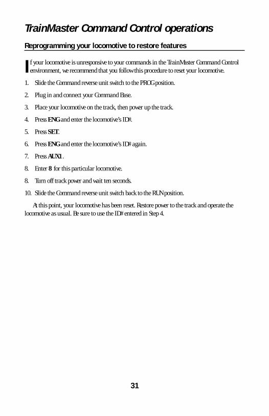
TrainMaster Command Control operationsReprogramming your locomotive to restore features
If your locomotive is unresponsive to your commands in the TrainMaster Command Controlenvironment, we recommend that you follow this procedure to reset your locomotive.
1. Slide the Command reverse unit switch to the PROG position.
2. Plug in and connect your Command Base.
3. Place your locomotive on the track, then power up the track.
4. Press ENG and enter the locomotive’s ID#.
5. Press SET.
6. Press ENG and enter the locomotive’s ID# again.
7. Press AUX1.
8. Enter 8 for this particular locomotive.
8. Turn off track power and wait ten seconds.
10. Slide the Command reverse unit switch back to the RUN position.
At this point, your locomotive has been reset. Restore power to the track and operate thelocomotive as usual. Be sure to use the ID# entered in Step 4.
31

Maintaining and servicing your locomotiveAdding fluid to your locomotive’s smoke generator
Your locomotive is equipped with a smoke generator that produces a safe, clean, whitesmoke during operation. In order to function, the smoke generator requires the periodic
addition of Lionel smoke fluid. A small bottle of smoke fluid is included with your locomotive. To add smoke fluid, lift away the roof-top hatch. Press down and unscrew the cap of the
smoke fluid bottle, then pierce the tip of the nozzle with a pin. Add 10 to 15 drops of fluid intothe hole as illustrated in Figure 6. When smoke production decreases, be sure to add four toeight additional drops of smoke fluid.
If you prefer to operate your locomotive without smoke, locate the smoke unit switch andslide it to the OFF position. Refer to Figure 5 for the location of this switch.
When the smoke unit switch is in the ON position, always keep a small amount of smokefluid in the smoke unit. Operating your locomotive’s smoke unit without smoke fluid will causedamage to the heating element.
Always operate your locomotive’s smoke unit with the addition of smoke fluid toprevent damage to the heating element.
32
Caution!
Figure 6. Smoke fluid
SMOKEOFF ↔ON
Add fluid here
SMOKEOFF ↔ON

Maintaining and servicing your locomotiveLubricating your locomotive
Help your Lionel locomotive lead a long and productive life on your railroad by maintainingit properly. To keep your locomotive lubricated, we recommend that you purchase a Lionel
Lubrication and Maintenance Kit (6-62927), available from your authorized Lionel dealer. When you find that the lubrication points illustrated in Figure 7 on page 34 appear dry,
lubricate your locomotive after you have removed any accumulated dirt and dust. There are twobasic rules to keep in mind when you are lubricating your locomotive: use only a small amountof lubrication and avoid getting grease or oil on your locomotive’s wheels, roller pick-ups, or thetrack.
Take care to avoid damaging the pantographs. Do not rest the locomotive on thepantographs.
33
Caution!

Maintaining and servicing your locomotiveLubricating your locomotive (continued)
34
FRONT
Figure 7. Underside details and lubrication points
Lubricate thebearings with
Lionel oilsparinglyLubricate the
gears with Lionelgrease sparingly
Lubricate thebearings with
Lionel oilsparingly
Lubricate thegears with Lionelgrease sparingly
REAR

Maintaining and servicing your locomotiveServicing your locomotive’s LEDs and lamps
Your locomotive is illuminated by several LEDs and lamps. While the LEDs are expected tolast for the life of the locomotive, you may find that the lamps may require replacement.
We recommend that you have the lamps serviced at an authorized Lionel Service Center. Seethe Lionel Service section on page 36 for more information.
Servicing the traction tires
Your locomotive is equipped with traction tires to increase the tractive effort of yourlocomotive and allow it to pull more cars at once.
During the course of normal operations, the traction tires may become worn out. Werecommend that you have the traction tires replaced by an authorized Lionel Service Centerbecause the truck and side frames must be removed to access the wheels. See the Lionel Servicesection on page 36 for more information.
Servicing the pantographs
Do not raise or lower the pantographs by hand.
Your locomotive is equipped with operating pantographs. Each pantograph is secured to thelocomotive with four mounting screws, which are removed using the small wrench that is
included with the locomotive. Because the pantographs are fragile, we recommend that youhave them repaired at an authorized Lionel Service Center. See the Lionel Service section onpage 36 for more information.
35
Caution!

Limited Warranty/Lionel Service
T his Lionel product, including all mechanical and electrical components, moving parts, motors andstructural components, except for light bulbs, is warranted to the original consumer-purchaser, for one
year against original defects in materials or workmanship when purchased through an authorized Lionelmerchant.
This warranty does NOT cover normal wear and tear, light bulbs, defects appearing in the course ofcommercial use, or damage resulting from abuse or misuse of the product by the purchaser. Transfer of thisproduct by the original consumer-purchaser to another person voids this warranty. Modification of this productvoids this warranty.
Any warranted product which is defective in original materials or workmanship and is delivered by theoriginal consumer-purchaser to Lionel L.L.C. or an authorized Lionel L.L.C. Service Center, together with proof oforiginal purchase will, at the option of Lionel L.L.C., be repaired or replaced, without charge for parts or labor. Inthe event the defective product cannot be repaired, and a replacement is not available, a refund of the originalpurchase price will be granted. Any products on which warranty service is sought must be sent freight or postageprepaid, as transportation and shipping charges are not covered by the warranty.
In no event shall Lionel L.L.C. be liable for incidental or consequential damages.Some states do not allow the exclusion or limitation of incidental or consequential damages, so the above
exclusion may not apply to you.This limited warranty gives you specific legal rights, and you may have other rights which vary from state
to state.
Instructions for Obtaining ServiceIf service for this Lionel L.L.C. product is required, bring the item, along with your dated sales receipt and
completed warranty information to the nearest Authorized Lionel Service Center. Your nearest Lionel ServiceCenter can be found by calling 1-800-4-Lionel, or by accessing our Website at www.lionel.com.
If you prefer to send your product back to Lionel L.L.C. for repair in Michigan, you must first call 586-949-4100 or FAX 586-949-5429, or write to Customer Service, P.O. Box 748, New Baltimore, MI 48047-0748,stating what the item is, when it was purchased and what seems to be the problem. You will be sent a returnauthorization letter and label to ensure your merchandise will be properly handled upon receipt.
Once you have received your return authorization and label, make sure that the item is packed to preventdamage during shipping and handling. We suggest that you use the product’s original packaging. Thisshipment must be prepaid and we recommend that it be insured.
Please make sure you have followed all of the above instructions carefully before returning anymerchandise for service. You may choose to have your product repaired by one of our Authorized Lionel ServiceCenters after its warranty has expired. A reasonable service fee will be charged.
Warranty InformationPlease complete the information below and keep it, along with your dated sales receipt. You must present
this and your dated sales receipt when requesting warranty service.
Name ________________________________________________________________________
Address ______________________________________________________________________
Place of Purchase ________________________________________________________________
Date of Purchase ________________________________________________________________
Product Number ________________________________________________________________
Product Description ______________________________________________________________
©2005 LIONEL L.L.C., CHESTERFIELD, MI 48051-2493UNITED STATES OF AMERICAPRINTED IN U.S.A.