Linux Board Port Overview for Sitara AM-Class Devices: AM33x, AM43x, and AM57x
1
Presenter
Presentation Notes
This training is going to discuss all the major steps used to port the Processor’s SDK Linux from a TI EVM to a Custom board.
Elements of a Linux Board Port
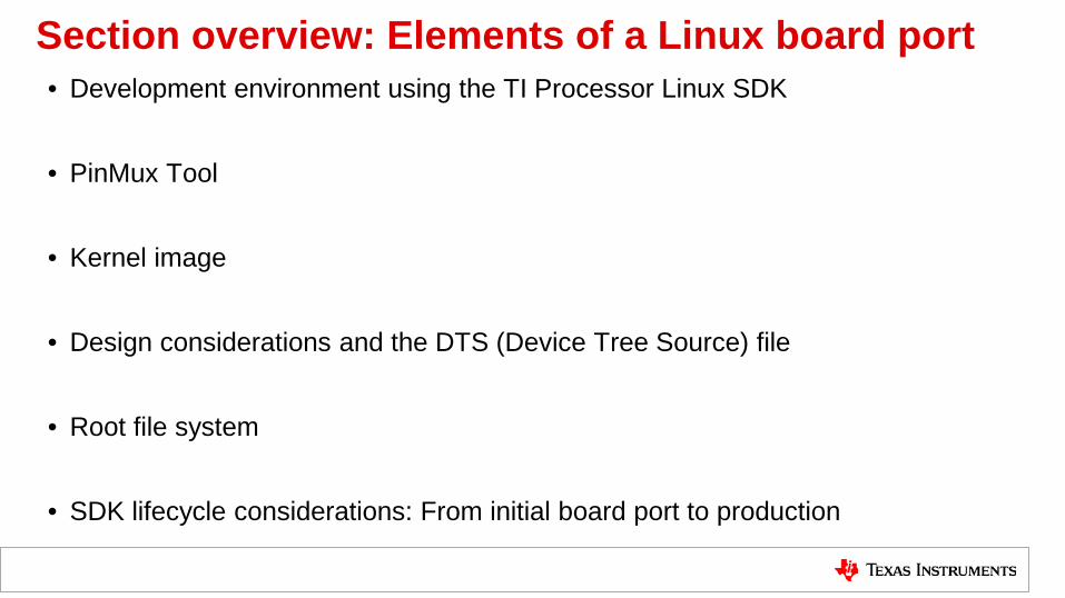
Section overview: Elements of a Linux board port • Development environment using the TI Processor Linux SDK
• PinMux Tool
• Kernel image
• Design considerations and the DTS (Device Tree Source) file
• Root file system
• SDK lifecycle considerations: From initial board port to production
Linux board port elements: Environment
PROCESSOR-SDK-LINUX-AMxx (installed on development machine)
Current 64-bit LTS Ubuntu Desktop (development machine)
Texas Instruments EVM (for processor of target product)
Presenter
Presentation Notes
This is the development eco-system that is recommended to develop a board port with as well as Linux applications. The environment uses a Linux PC running the latest LTS Ubuntu that has the Processors Linux SDK installed on it. In the diagram also is a TI EVM that is used for evaluation and early development. The EVM is connected via a serial cable for the linux console and an ethernet cable that could be used for all kinds of tasks. At this point the environment is probably already setup. But we are mentioning it here for completeness.
Linux board port elements: PinMux Tool • Each peripheral requires a pinmux
definition. • The PinMux Tool assists with
determining a mux configuration for a system based on use-case peripheral requirements.
• The output from the tool is then incorporated into DTS files for binding peripherals to a system application.
• Below is the PinMux Tool download link and associated Wiki resources. http://www.ti.com/tool/pinmuxtool http://processors.wiki.ti.com/index.php/TI_PinMux_Tool_v4
Presenter
Presentation Notes
What is the pin mux tool and why do I need it? Each peripheral that is used in the SOC must have pins assigned by a pin mux setting otherwise the peripheral is not connected. Animate A particular use case peripheral mix usually only uses a subset of the IP integrated into the SOC. A simple example would be a use case may only need 1 uart but the IP contained within has up to 6. There are several peripherals that have the ability to provide multiple interfaces. For the system designer they must a define a pin mux for the SOC application , this can be a challenge since the each peripheral is available on different pins to help with reducing the possibility of conflicts for layout and peripheral mix choices. Animate The pin mux will generate pin mux data files that can included as part of a DTS file for a custom board. The DTS file will be explained later and how it is used in porting to a custom board. The links at the bottom show the location for the tool and a support page.
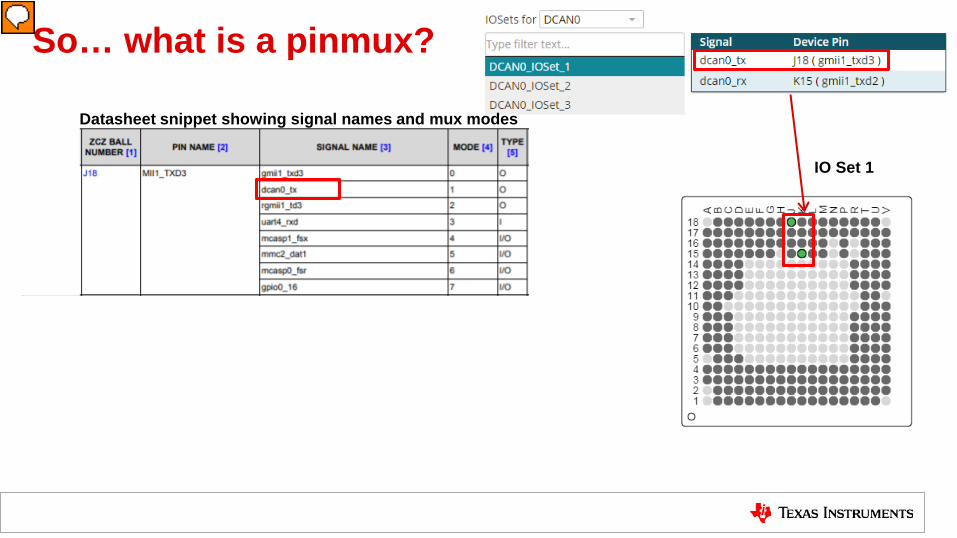
A question at this point might be what is pin mux. In a very brief statement, pin mux allows selecting one signal from a set of different peripheral signals to be assigned to a pin on the package. The default for a mux mode is GPIO mode. If a peripheral is desired to be used it will not have access or be accessible until all the pins are set to a mode that assigns the pin to a peripheral ip. Here we will go through and quickly build an example of how pin mux will work. This a partial screen capture from the pin mux tool. The user has selected the DCAN0 interface, the tool has automatically assigned a set of pins, typically the tool will do this and try to resolve pin assignment conflicts. The pin mux is using device pins J18 and K15 for the DCAN0 interface.
So… what is a pinmux?
IO Set 1
Presenter
Presentation Notes
In this example J18 is using mux mode 1 which is the DCAN0 TX signal. Also note the pin mux tool has selected IO set1, this could change when later assignments cause conflicts the pin mux tool will try to resolve them. The green dots represent the pins in the BGA of the example package. We will just concentrate on J18 for this example.
So… what is a pinmux?
IO Set 1
Datasheet snippet showing signal names and mux modes
Presenter
Presentation Notes
So how does this relate to the information found in the datasheet. In the snippet here from a datasheet you can see the signal name wanted is a mode of the pin name MII1_TXD3 which is pin J18. please notice that the pin name and the actual signal muxed can be different.
So… what is a pinmux?
Pin Mux
J18
IO Set 1
Datasheet snippet showing signal names and mux modes
Presenter
Presentation Notes
So looking at the datasheet you can see all the possible signals that can be muxed for J18.
So… what is a pinmux?
Pin Mux
J18
IO Set 1
Datasheet snippet showing signal names and mux modes
Presenter
Presentation Notes
So tying it together, J18 whose Pin name is MII1_TXd3 can have it’s mux mode to 1 which is DCAN0_tx and would then be configured to output on pin J18.
So… what is a pinmux?
Pin Mux
J18
J18 = MII1_TXD3.dcan0_tx
IO Set 1
Datasheet snippet showing signal names and mux modes
Presenter
Presentation Notes
This equation like reference here is another way to view the mux assignment for J18, which is being set equal to pin name and the signal name muxed in. Pin or Ball J18 whose pin name is MII1_TXD3 is set to signal name dcan0_tx which is mode 1 and is an output signal. A lot schematics show this naming for a pin and the DTS output of the pin mux tool follows a similar concept.
So… what is a pinmux?
Pin Mux
J18
J18 = MII1_TXD3.dcan0_tx
IO Set 1
Datasheet snippet showing signal names and mux modes
Presenter
Presentation Notes
After pin assignments are made, the pin mux tool has the ability to output a DTS file that defines the pin mux. In the slide here is a essentially a snippet of what the Pin Mux Tool output looks like. The tool will define a macro for the pin and in the comments show the pin name and signal name for the pin. A later presentation will go into more detail on how the pin mux tool will be used across the AM3/AM4/AM5 devices.
Linux board port elements: Linux kernel • The TI Kernel in Processor SDK Linux
has at least these elements: – The kernel configuration – Modules compiled against the TI SDK
kernel configuration – A board DTB (Device Tree Blob)
file
Kernel Modules
Configuration
Board DTB
• The system developer should use the kernel from the TI SDK or a tagged release of the TI Kernel Tree.
• The SDK default kernel configuration is recommended to get started with the port.
Presenter
Presentation Notes
Here is the key portion of the port, the Linux Kernel. The Linux Kernel at least 3 elements used on a board port For a board port may depend on the kernel configuration, the modules built in or out of the kernel using the kernel configuration Board DTB, this defines the peripherals that are on the custom board. A developer could start with minimal start of device drivers enabled, Kernel modules, all of these are available in the TI SDK pre-built images The key thing here is getting to a command prompt first during the first board port bring up, then as the port proceeds to a full feature more modules can be added in. The source of the kernel used should come from a TI SDK or a cloned TI kernel tree and use a tagged release.
A lot of questions seen on the TI e2e forum are if a certain peripheral has support in the kernel. This is good question to ask at board design time because depending on the answer this may save time and money. If the device doesn’t have support in the mainline kernel then an out of tree driver may have to be used and accounted for in how much project time will be necessary to support the out of tree driver. Looking at the block diagram as an example, (animate) the block circled are examples of support questions that get asked. Do these components have drivers? For example a lot of Ethernet PHYs have driver support already in the kernel, (animate) but it is good to check the kernel sources with a grep to find the existence of the driver for the component selected. (animate) In this case we are looking for a particular driver. After finding the component with the grep the driver should be enabled in the kernel configuration. (animate) In this example the driver exists and is already enabled in the kernel.
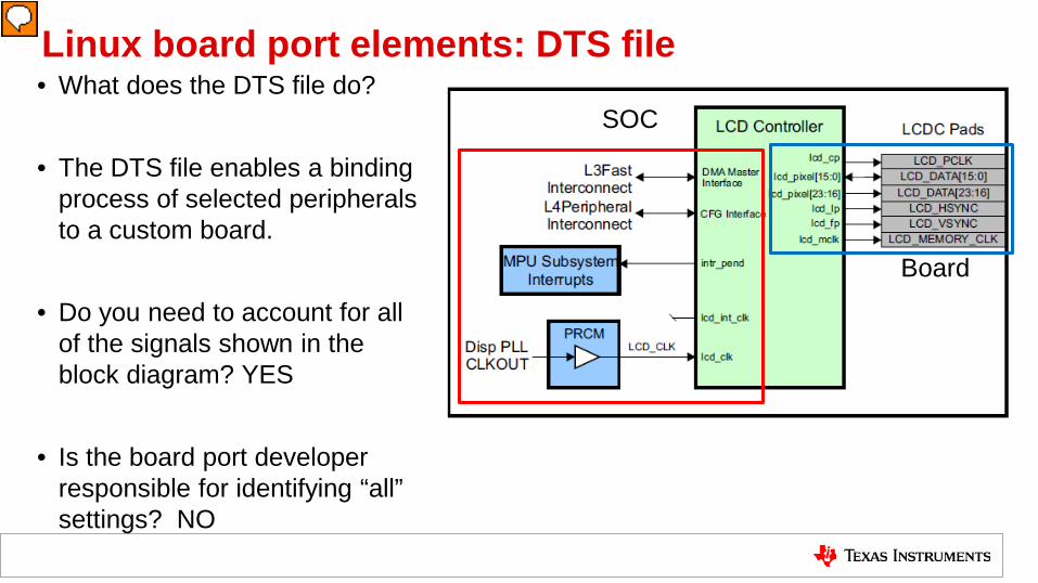
Linux board port elements: DTS file • What does the DTS file do?
• The DTS file enables a binding
process of selected peripherals to a custom board.
• Do you need to account for all of the signals shown in the block diagram? YES
• Is the board port developer responsible for identifying “all” settings? NO
Board
SOC
Presenter
Presentation Notes
What does the DTS file do? Or for that matter what is the DTS file. This is a device tree source file, it is developed for a custom board and it is compiled and read in by the kernel during boot. The DTS file defines for a peripheral the necessary clocks, interrupts, bus usage, peripheral configuration and pin mux. The Linux kernel uses the information to determine what peripherals are enabled for the board it is running on. If you remember from earlier in the presentation the ARCH/SOC/Board abstraction, the block is showing the breakdown of the SOC and the board portion of the abstraction. The signals shown in the ip block diagram must be accounted for. Some signals are the always the same and do not vary between board ports, this would be the red box. Note this is the SOC portion of the port abstraction. Some signals do vary such as the ones in the blue box. These signals vary depending on usage on an actual board. These signals are non-discoverable and would be defined as part of a unique board DTS.
DTS file components TI EVM DTS files may include: • DTSI (Device Tree Source Include) files • Other DTS files • Here the am33xx.dtsi is the processor
Overview of the hierarchy of the DTS file for a custom board. The DTS file can contain several DTSI and in fact sometimes DTS files. A DTSI is DTS include file, it is required to be included in a DTS file. The different DTSI files assist with realizing the board port abstraction presented so far. Please note how the port ARCH/SOC/Board abstraction is being realized here, only the SOC and Board portions of the abstractions are used in the DTS context. To assist with the port abstraction there is a processor DTSI file that contains node definitions for describing the SOC itself as well as all the peripherals of the selected processor. The DTSI is used as an include file for a board DTS file. Following the red and blue boxes from the earlier slide, the red box represents the SOC portion of the port abstraction that is provided by TI and rarely do these files need to be changed to implement a port. The blue box represents the board portion that the custom board developer will need to develop. Typically these DTSI files should be used as is and should not be edited. The main reason is that TI may make peripheral node definition changes during development of an SDK release. If the board developer has made changes to the TI processor DTSI for example, and the next release of the SDK may have made changes to this file board developers wishing to pick up the changes byupgrading will now require a merge which may not be trivial.
DTS file example structure • HelloWorld-like minimal
board DTS file (initramfs)
• Defines the Processor used
• UART node and supporting pinmux
• Can also use EVM DTS file and disable all the nodes ... except UART.
Besides determining the kernel configuration, this is where the custom board developer will be spending their time. (animate) This is a very brief example of more of a hello world type DTS base file. This file will be covered in more detail in a later presentation. There is also another presentation that TI has that explains the syntax of a DTS file. The main purpose of the DTS is to define board information that is not discoverable concerning the peripherals in use and necessary parameters about those peripherals. (animate) In this example the processor is defined, (animate) the uart console and the pin mux definition necessary to support that peripheral. This file is mostly complete, we will explain in a later presentation about what is missing. (animate) If you prefer you could take a TI EVM DTS file and start with that, but it would be recommended to disable all nodes except for UART.
Linux board port elements: Root filesystem • “Everything is defined as a file in
Linux.” • The files are organized into a
directory structure called the root filesystem, mostly for human consumption.
• This structure provides a natural hierarchy of abstraction between the kernel and the user applications.
/ bin boot dev etc home include lib media mnt opt proc run sbin srv sys tmp usr var www
Presenter
Presentation Notes
Defining what the Root Filesystem and how it matters to the Board port process. (animate) The kernel needs one no matter what, some of the directories are key to the operation of the kernel: bin, dev, proc, sys, everything is defined as a file and the root file system is where they are stored. (animate) The root filesystem can be visualized as the top of the hierarchical file tree, though be aware this is for human readability. The root filesystem contains the files and directories critical for system operation, including the device directory and programs for booting the system. Linux uses a file i/o approach for accessing among other things the peripherals of the SOC in the dev directory. (animate) From the kernel perspective a root file system is a collection of “linked” inodes, both directories and files are represented as an inode forming a tree in what is described as a natural heirarchy. The mounted root file system is always inode #2, from this inode all other directories and files are linked. Generation of a root file system is a significant topic that will be expanded on in a later presentation. This is a very brief description of a root file system, the summary is that the Linux kernel needs a root file system to boot into a some sort of user space so an application or applications can run.
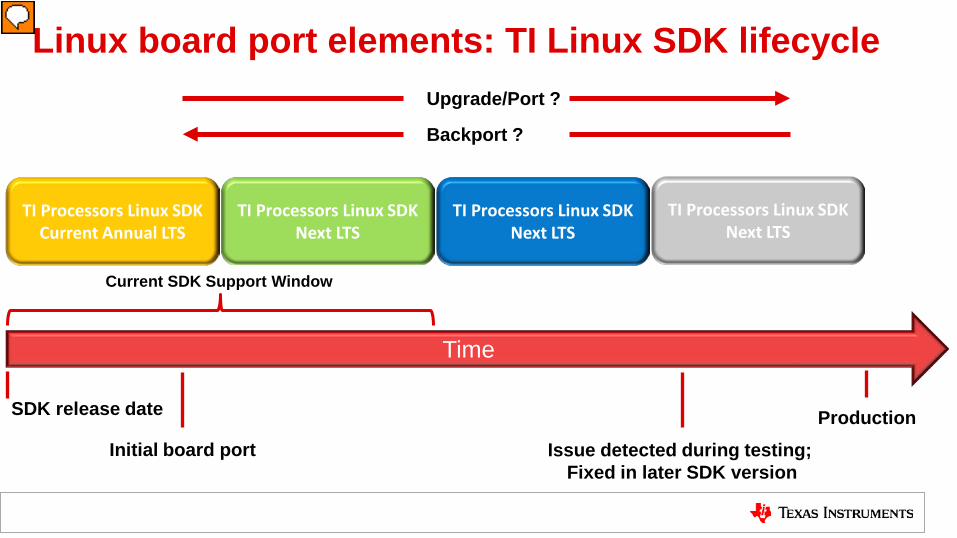
Linux board port elements: TI Linux SDK lifecycle
TI Processors Linux SDK Current Annual LTS
Initial board port
Time
TI Processors Linux SDK Next LTS
Production
TI Processors Linux SDK Next LTS
TI Processors Linux SDK Next LTS
SDK release date
Current SDK Support Window
Issue detected during testing; Fixed in later SDK version
Backport ?
Upgrade/Port ?
Presenter
Presentation Notes
Products have been demonstrated to take years sometimes to get to production…. And most projects usually have remained on the initial ported TI SDK during their development cycle. The TI SDK will be updated multiple times a year. Please be aware that TI support only lasts two years after an SDK release. Sometimes final product testing reveals an issue that was fixed in a later SDK then the one product was developed on. To resolve the found issue a decision will need to be made whether to upgrade to a later SDK that fixes the issue or try to back port the fix to the SDK the product is based on. This decision can be complicated as neither path is easily determined. Product developers need to track TI SDK releases for new features, bug fixes. The critical point to be made here is that TI does not maintain a set of patches for any changes between SDK releases, much less spanning multiple releases. The custom board developer should take note that there will a continuous release of SDKs from TI and be aware that a later release may fix something discovered during their testing of their product based on an older SDK. The decision will be up to the custom board developer if they want to perform an upgrade or the backport to resolve the issue.
Summary: Elements of a Linux board port
Download SDK for
EVM
Set up environment
Use pinmux for custom
board
Create minimal DTB
for new board
Boot SDK kernel with
SDK RootFS
Iterate to add functionality
Presenter
Presentation Notes
We have covered a lot of material, so let’s summarize the elements again of a Linux Board Port. Now we will step each element here and provide a summary of each. A custom board derived from a TI EVM, The development eco-sytem, The Processors Linux SDK, The pin mux tool will used to create a custom board DTS, a kernel configuration for the board kernel and starting off with one of the TI default root file systems.
Summary: Elements of a Linux board port
Download SDK for
EVM
Set up environment
Use pinmux for custom
board
Create minimal DTB
for new board
Boot SDK kernel with
SDK RootFS
PROCESSOR-SDK-LINUX-AMxx
Presenter
Presentation Notes
The first step which was most likely already done for the u-boot board port is to download and install the TI Proceesors SDK Linux package and install in Linux desktop preferably running an LTS Ubuntu.
Summary: Elements of a Linux board port
Download SDK for
EVM
Set up environment
Use pinmux for custom
board
Create minimal DTB
for new board
Boot SDK kernel with
SDK RootFS
Presenter
Presentation Notes
After installing the TI Proceesors SDK Linux package there are setup scripts that can be run to assist with setup of the development environment. There is a TI presentation called hands on with the SDK that is recommended that goes into these steps in more detail.
Summary: Elements of a Linux board port
Download SDK for
EVM
Set up environment
Use pinmux for custom
board
Create minimal DTB
for new board
Boot SDK kernel with
SDK RootFS
Presenter
Presentation Notes
Next you will download and install the TI Pin Mux tool, this will be used during the port process for getting the DTS output files for the kernel and u-boot.
Summary: Elements of a Linux board port
Download SDK for
EVM
Set up environment
Use pinmux for custom
board
Create minimal DTB
for new board
Boot SDK kernel with
SDK RootFS
Presenter
Presentation Notes
This is the hello world step that you should do for the first bring-up of linux on a custom board, create a minimal configuration of the board interfaces, typically just a UART and where the root file system will be mounted. You are only interested in getting to that first command prompt when booting Linux for the first time. The rest for the board can be added iteratively to the DTS to enable more board features.
Summary: Elements of a Linux board port
Download SDK for
EVM
Set up environment
Use pinmux for custom
board
Create minimal DTB
for new board
Boot SDK kernel with
SDK RootFS
Linux Kernel Config Linux Kernel
Root File
System
Presenter
Presentation Notes
As mentioned earlier you need a root file system to boot, the ones in the SDK can be leveraged here for initial bring up. Later on as the port progresses the actual file system for the product can be built
Summary: Elements of a Linux board port
Download SDK for
EVM
Set up environment
Use pinmux for custom
board
Create minimal DTB
for new board
Iterate to add functionality
Presenter
Presentation Notes
This last element shows the iterative approach that you should use, Start with a minimal DTS and you can add functionality one node (interface) at a time. Keep iterating until all the required interfaces have been added. This should be easier than trying to write the entire custom board DTS at the beginning
Conclusion: Elements of a Linux board port • Development environment using TI Processor SDK Linux