dowrorissa.gov.indowrorissa.gov.in/guideline/canal lining work.pdf · the tile shall...
TRANSCRIPT
-,__.
Office of the Engineer-in-Chief,Water Resources, Odisha, Bhubaneswar.
No. Proc-Misc-Guideline-8/18 (/]l/,3';' ~ B-.From / {l
Dated. I ~ ~()d 1>/9
To
Sri O.K. Samal,Chief Engineer (M&E).
TheAll Chief Engineer& BasinManagers/,Chief Engineers/ChiefConstructionEngineers.
Sub: Approval of Guideline /Manual for Canal Liningworks.
Sir,
~ ',~, ,/ , With reference to the subject cited above, it is to enclose herewith copy of the~t+~DOWR lr.Np.3503IWR dated 7.2.2019 for approvedGuideline /Manual for Canal Liningworks
\_tA,.~ and you are rquested to strictly follow the guidelines in execution of Canal Lining works.The
above Guideline/Manual has been uploaded in the DoWR website www.dowrodisha.gov.in/Downloads.
Encl:As above
Yours faithfully,
~9Chief Engineer(M&~
~4f ..E8' :;:;. /6 . <7~.f? ~Copy forwar ed to Deputy Director,M.I.S.,O/o the Engineer-in-Chief,W.R.,
Bhubaneswar for information and necessary action. He is requested to upload the aboveGuideline/Manual for Canal Lining works in the DoWR .website www.dowrodisha.gov.in/Downloads.The copy of the DoWR lr.No.3503IWR dated 7.2.2019 and the Guideline/Manualisenclosed.
Memo No.
Encl:As above ~;/Chief Engineer(M&E).
321

I/
GOVERNMENT OF ODISHADEPARTMENT OF WATER RESOURCES
BHUBANESWAR***
No.WR.MAJI-SCH-0005-2018_...:...3_SV_·_J__ --.:Nl/R, dated J-/3:£.L1i i~/~"?:-'..~;0~~:\
I,' I... '-.':,'!/(~.' -t: 'i~..' ! './
The Engineer-in-C ie, .ater Resources, ;i l..l i 'l1 \}ftc:' "l:.Sechasadan, Bhubaneswar \<~.\. _......'~~".-?/\.//
. \ \~; .'.... ~ ,.' \, .: ,,~ .' .:-\/:>'Sub:» Approval of Guideline IManual for Canal Liningworks. '<....< ' . ~:__ '.r..' /./
FromSri N.R. Swain,
F.A-cum-AdditionalSecretary toTo
Sir,Inviting reference to the subject mentioned above, I am directed to intimate
that the Government in Water Resources Department have been pleased toapprove the draft Guideline, I Manual for Canal Lining works received videyour letter No. 30370, dated ,05.11.2018 and to return the same herewith fortaking further necessary- action at your end. The approved guideline becirculated among all field level Authorities I Officers under your administrativecontrol with instruction I advice to strictly follow the guideline in executingtheworks under the scheme.
Yoursfaithfully,
MemoNo._..Loc3.02~----,-.+-t; ~MlR, dated l-/Y-//~Copy forwarded to the E.I.C-cum-Special Secretary to Government,DOWR,
for information and necessary action.
F1~j ;ft'~F.A-cum-Addilional~o<t\>'V\,~~meht
to .'1
Draft CopyOnly for Official Use
GUIDELINES FOR LINING OFIRRIGATION CANALS
Government of OdishaDepartment of Water Resources
i ._"
'....'SI.No12345
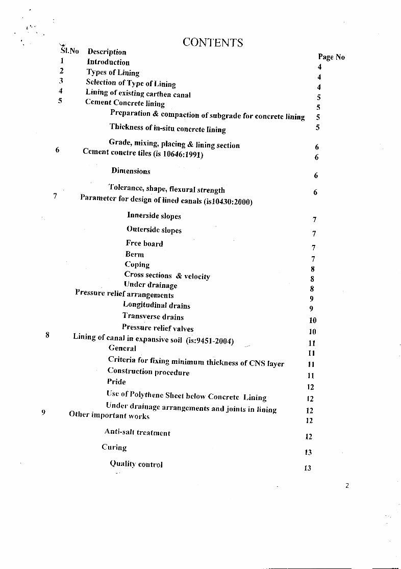
CONTENTS
6
DescriptionIntroductionTypes of LiningSelection of Type of LiningLining of existing earthen canalCement Concrete lining
Preparation & compaction of subgrade for concrete lining
Thickness of in-situ concrete lining
Grade, mixing, placing & lining sectionCement conctre tiles (is 10646:1991)
Dimensions
7Tolerance, shape, flexural strength
Parameter for design of lined canals (isl0430:2000)
Page No4445555
66
6
6
Innerside slopes 7Outerside slopes 7Free board 7Berm 7Coping 8Cross sections & velocity 8Under drainage 8Pressure relief arrangements
9Longitudinal drains 9Transverse drains 10Pressure relief valves 108 Lining of canal in expansive soil (is:9451-2004) IIGeneral
IICriteria for fixing minimum thickness of CNS layer IIConstruction procedure IIPride
12Use of Polythene Sheet below Concrete Lining 12Under' drainage arrangements and joints in lining 129 Other important works
12Anti-salt treatment 12Curing
13Quality control 13
2
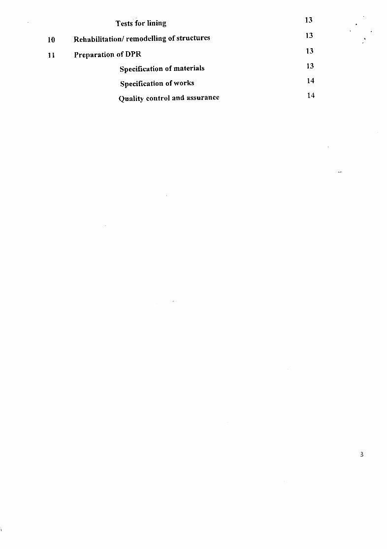
Tests for lining 13
10 Rehabilitation/ remodelling of structures 13
11 Preparation of DPR 13
Specification of materials 13
Specification of works 14
Quality control and assurance 14
3
GUIDELINES FOR LINING OFIRRIGATION CANALS
*********1.0 INTRODUCTION
Irrigation canals are important infrastructure and contribute to the development ofsustainableagricultureand agriculturalactivities.At present, there are sixty(60)major& mediumirrigation projects and a good number of MIPs with vast canal networks are operational in thestate. Most of these Projects are quite old and serve the state for more than thirty(30) years.The canal systemsof these projects are earthen and gets deterioratedduring courseof its use.Seepage losses in these canals are prominent and they are unable to carry the designdischarge. Renovation, re-sectioning & reduction in seepage loss are essential for smoothfunctioning of these canals. With this background, department of Water Resources hasformulated'a proposal viz. Canal Lining & System Rehabilitation Programme(CLSRP) during2013 and placed it for approval of Government. Considering its importance,the State Cabinetin its meeting held on 27.11.2013 approved the scheme formulated by the department.Further,in the samemeeting, Cabinet had also taken a decision that all the new canals in the State willbe designed as lined canals and existing canals may also be considered to be converted tolined canals in due course in a phased manner for prevention of seepage loss and for optimaland judicious use of water.
To implementthe CLSRP scheme, one operating guideline containingProjectSelectionCriteria, preparation and approval of Project Reports, financial arrangement, monitoring andevaluation etc. for the said scheme was prepared and approved by DOWR vide letter no.Irr.I.WB-12/2013-8984 dtd 16.03.13. It is observed that field officers are more often facingdifficulties in preparation of Detailed Project Report (DPR) due to want of technicalguidelines.To obviate this difficulty and to follow a unified approach, it is felt that one technical guidelinemay be preparedand circulated to field engineers for their use.2.0 TYPESOF LINING
Lining is an impermeable layer provided for the bed and sides of canal to improve the lifeand discharge capacity of canal. 60% to 80% of water lost through seepage in an unlined canalcan be saved by construction of appropriate canal lining.
• Rigid Lining : In situ Cement concrete/Cement fly ash concrete! ReinforcedCementConcrete
• Semi-Rigid Lining: Pre-cast Cement Concrete Tilel Cement concreteslabl Cement flyash concrete tile/Fly ash brick or tile lining
• Flexible Lining : Geo-membrane like High density polyethylene(HDPE)1 Poly vinylChloride(PVC)/Lowdensity polyethylene(LDPE)
• Combination Lining: Membrane in the bed and brick/tile or concrete liningon sides.3.0 SELECTION OF TYPE OF LINING
While selecting the type of lining, the Engineer in Charge should collect information onthe position of water table, climatic conditions, availability of construction materials, type ofsubgrade, time schedule, performance of lining in the existing canals in the adjoining areas.
4
After collecting the above information, the entire canal or specific reaches of canal to be linedmay be decided. Besides, for selection of particular type of lining, seepage loss, economy,
~.structural stability, strength and durability, reparability and ease of maintenance, resistance to"¥
erosion,maximum-hydraulicefficiencyetc. are requiredto be taken in to consideration.
Selection of Canals! stretches of canals should be judicious and based on adequatejustification. Project Authority has the final choiceto decide the type of lining.
4.0 LININGOF EXISTINGEARTHENCANALS
It is seen that design section of earthen canals during course of use getsdeformed/deterioratedand looses its original shape (DesignedTrapezoidal section). Therefore,before taking up the lining work, proper sectioningof canals to pass the design dischargearerequired to be done. The lining work in existinqearthencanals may be done in such a way thatthe canal hydraulic particulars such as Full supply level (FSL) and Full supply design dischargewill remain unaltered after lining. After lining of earthen canal, Manning's RugosityCoefficient(n) will be reduced and there will be increase in the velocity. The Engineer in chargeshouldseethat the FSL should not be lowered, otherwisethe outlets and off-taking canals will be affectedin drawing it's full discharge due to reduction in the driving head. To take care of the aboveproblem, the canal section is to be redesignedkeepingthe full supply level as per the approvedLS & DS and by adjusting the full supply depth, bed width and side slope as per siterequirement. using the Manning's coefficient (n) for lined canal in accordancewith the relevantIS codes.
In expansive soils such as canal in black cotton soil, suitable provision of CNS layer asper the recommendation of relevant IS codes may be made. Similarly in cutting reacheswithhigh ground water table, unstable side slopes etc., necessary measures as recommendedinrelevant IS codes, Manuals on canal lining (revised)prepared by INCIDmay be adopted.
5.0 CEMENTCONCRETE LINING (IS 3873:1993)Plain cement concrete lining will be suitable for all size of canals on firm soils.
Reinforcement in canal linings is normally not required if transverse joints are providedat properintervals(less than 6 m) to avoid cracks except in specific areas. RCC lining is justified underunusual conditions such as high back pressure, high flow velocities, swelling soils, unstablesub-grade and in reaches where the canal crosses large cross drainageworks.
a. PREPARATION & COMPACTION OF SUBGRADE FOR CONCRETELINING
The subgrade should be prepared, dressed and rolled true to level and accordingto therequired cross section of canal to form a firm compactedsubgrade for the lining.For preparationof subgrade IS 9451 : 1985 may be followed for expansive soil, IS 3873:1993may be followedfor ordinary soil, rock and sandy soil.
b. THICKNESS OF IN-SITU CONCRETE LINING
The thickness of lining should be fixed depending upon the nature of the canalrequirement, namely, hydel channel or irrigation channel, full supply depth and channelcapacity. Hydel channel should have a greater thickness than channels meant for irrigationbecause of drawdown effects and where closure for repairs may not be usual. Deeperchannelsshould have greater thickness than shallow depth channels. Minimum thickness of canal liningbased on canal capaciti~s is given in table below.
5

.1
Capacityof Canal (cumecs) DepthofWater (m) Thicknessof Lining (mm)0-5 0-1 50-605-50 1 - 2.5 60-75
50-200 2.5.- 4.5 75-100200-300 4.5 - 6.5 90-100300-700 6.5 -9.0 120-150
Table No:1Thickness of In-Situ Concrete Lining (IS: 3873-1993)
Table No:2Tolerance in Concrete thickness, Alignment, grade (IS: 3873-1993)
Description Allowable Limitpeparture from establishedalignment 20 mmon straight reaches
50mmon partial curves or tangentspeparture from establishedgrade 20 mmon small canals~ariation in concrete, lining thickness ± 10 mm provided average thickness is not
less than specified thickness
C. GRADE, MIXING, PLACING& LINING SECTION
The concrete used for lining should be design mix concrete of grade M 15 and shouldconfirm to requirement of IS 456:2000 The concrete should be mixed by mechanicalmeans,hand mixing is not allowed. All the in-situ concrete lining are to be done strictly using paver.Manual placing of concrete for concrete lining is not allowed under any circumstancesfor anytype of canal. Trapezoidal section of lining should be adopted in all canals. In vulnerablereaches, in toe of hillocks and in extra ordinary cases in view of stability of side slopes,rectangular section with vertical RCC retaining walls may be adopted under approval ofthe competent authority. Suitable transition in 3:1 is to be provided to negotiate to thetrapezoidal section. However, the canal section up to 1.5 m bed width (widthof lined section)may be providedwith rectangular lining sectionwith RCC cantilever walls with gradeof RGGasper the exposure conditions as recommended in IS: 456-2000 when the trapezoidalliningusingpaver is not feasible.
For water course & Field channels( CAD), rectanqular RCC section with bed width of300 mm along with provision of 8 mm diameter reinforcement@ 200 mm clc on bothwayswitha clear cover of 30mm may be made. The reinforcement is to be provided on earthenside ofboth the walls and the bed. Thickness of the RCC should be 100mm.
6.0 CEMENT CONCTRE TILES (IS 10646:1991)
a. DIMENSIONS
The nominal dimension shall be 500 mm x 500 mm, 500 mm x 250 mm,400mmx 400mm, 300 mm x 300 mm and 250 mm x 250 mm. Each of these shall be manufacturedin thethicknesses 60, 50 and 40 mm. However, other sizes other than given abovemay also bemanufactured if required.
b. TOLERANCE,SHAPE,FLEXURALSTRENGTH
6
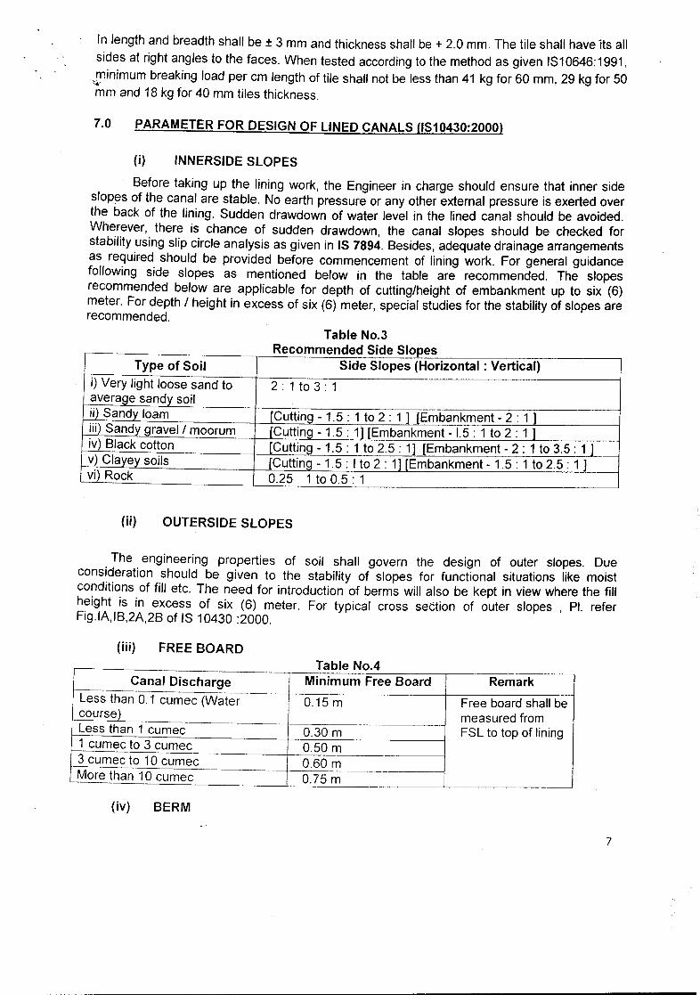
In length and breadth shall be ± 3 mm and thickness shall be + 2.0 mm. The tile shall have "itsallsides at right angles to the faces. When tested according to the method as given IS10646:1991,
--minimum breaking load per cm length of tile shall not be less than 41 kg for 60 rnm, 29 kg for 50'*'mm and 18kg for 40 mm tiles thickness.
7.0 PARAMETERFOR DESIGNOF LINEDCANALS (1810430:2000)
(i) INNERSIDESLOPES
Before taking up the lining work, the Engineer in charge should ensure that inner sideslopes of the canal are stable. No earth pressureor any other external pressure is exertedoverthe back of the lining. Sudden drawdown of water level in the lined canal should be avoided.Wherever, there is chance of sudden drawdown, the canal slopes should be checked forstability using slip circle analysis as given in IS 7894.Besides,adequatedrainage arrangementsas required should be provided before commencement of lining work. For general guidancefollowing side slopes as mentioned below in the table are recommended. The slopesrecommended below are applicable for depth of cutting/height of embankment up to six (6)meter. For depth / height in excess of six (6) meter, special studies for the stability of slopesarerecommended.
Type of Soil Side Slopes (Horizontal: Vertical)i) Very light loose sand to 2 : 1 to 3 : 1average sandy soilii) Sandy loam [Cutting - 1.5 : 1 to 2 : 1 ] lEmbankment - 2: 1 ]iill Sandygravel/ moorum [Cutting - 1.5 : 1] [Embankment- 1.5: 1 to 2 : 1 ]iv) Black cotton [Cutting - 1.5 : 1 to 2.5 : 1] [Embankment- 2 : 1 to 3.5 : 1 ]'1Clc!yeysoils [Cutting - 1.5 : I to 2 : 1] [Embankment- 1.5 : 1 to 2.5 : 1 ]vi) Rock 0.25 1 to 0.5 : 1
Table No.3Recommended Side Slopes
(ii) OUTERSIDESLOPES
The engineering properties of soil shall govern the design of outer slopes. Dueconsideration should be given to the stability of slopes for functional situations like moistconditions of fill etc. The need for introduction of berms will also be kept in view where the fillheight is in excess of six (6) meter. For typical cross section of outer slopes , PI. referFig.IAIB,2A2B of IS 10430 :2000.
(iii) FREE BOARD
Canal Discharge Minimum Free Board RemarkLess than 0.1 cumec (Water 0.15 m Free boardshallbecourse) measuredfromLess than 1 cumee 0.30 m FSL to top of lining1 cumee to 3 cumec 0.50m3 cumec to 10 cumec --
0.60 mMore than 10 eumec ---
0.75 m
Table No.4
(iv) BERM
7

In deep cut reaches of canals with discharge capacity exceeding 10 cumecs, berms of3m to 5m width should be provided in each side for stability as well as for easy maintenance .
._.,Turfingis to be done on the inner side slopes above the berms.
(v) COPINGThe Engineer in charge should take adequate measures so that no rainwater shall beallowed to flow or percolate towards the canal slope behind lining. To check the ingress of rainwater behind the lining of side slopes of the canals, horizontal cement concrete coping 100 mmto 150 mm thick, depending upon size of canal should be provided at the top of lining. The widthof coping at the top shall not be less than 225 mm for discharge up to 3 cumecs, 350 mm fordischarge more than 3 cumec and 550 mm for discharge more than 10 cumec.
(vi) CROSSSECTIONS & VELOCITYTral?ezoidal section is the preferred section for all types of lined canals. However, for
small canals with discharge capacity up to 3 cumecs, cup shaped sections may be used. Themaximum permissible velocities for different types of linings are as follows .
./ Cement concrete lining - 2.7 m/s
../ Burnt clay tile or brick lining 1.8 m/s
../ Stone-pitched lining 1.5 m/sWhile designing lining, critical velocity ratio should be aimed at higher than unity so that
silting will not take place in the lined canal.
(vii) UNDER DRAINAGEEmbankments of relatively permeable soil do not need drainage measures behind the
lining. However, drainage measures to be provided if the lined canal passes through an areawhere seasonal ground water level is higher than water level inside the canal, where sub-gradeis sufficiently impermeable to prevent free drainage of seepage or leakage from canal, wherethere is built up pressure due to time lag drainage of the sub-grade following drawdown of
canal. TableNo.5DDt ·1ramage e at s
SI.No Types of Sub-gradePosition of Water Table
Below Canal Between Canal Bed Above Canal
Bed Level Level and F.S.L F.S.L
1 Subgrade Free No drainage Drainage Drainage
Draining [Soil arrangement is arrangement arrangement is
comprising gravel with required required. 150 mm to required. 150 mm
sand,or sandy soil200 mm thick layer to 200 mm thick,
having permeability of well designed layer of well
(K) greater than 10.4 I filter below lining designed filter
ern/sec] \should be below lining
should be provided
2 Subgrade Poor Drainage Drainage Drainage
Draining arrangement arrangement arrangement is
[Soil comprising very required. 150mm required. 150 mm to required. 200 mm
fine sand, admixture to 200 mm thick 200 mm thick layer to 300 mm thick,
of sand, silt and clay layer of well of well designed layer of well
or soil having designed filter filter below lining designed filter
L..___. permeal5ility (K) below lining should be provided below lining
8

r between 10-4 cm/sec should be should be provided
~and 10-6cm/sec] providedSubgrade Practically Drainage Drainage Drainage
1-4 Impervious arrangement arrangement arrangement is[Soil comprising of required. The required. The required. Thehomogeneous clay subgrade should subgrade should be subgrade shouldwith permeability (K) be removed to a removed to a depth be removed to aless than 10-6 cm/sec] depth of 600 mm of 600 mm and depth of 600 mmand replaced by replaced by sand, and replaced bysand, murrom or murrom or suitable sand, murrom orsuitable pervious pervious material suitable perviousmaterial material
(viii) PRESSURE RELIEF ARRANGEMENTS
Embankments of relatively permeable soil do not need drainage measures behind thelining. However, drainage
TableNo.6Pressure relief arrangement details
SI.No Types of Sub-grade Position of Water TableCanalBelow Canal
Level
-do- -do-
Bed Between Canal AboveBed Level and F.S.L.F.S.L1 Subgrade Free No pressure relief
Draining [Soil arrangementcomprising gravel with requiredsand,or sandy soilhaving permeability (K)greater than 10-4cm/sec]
Bed-Longitudinal& Transversedrains withpressure reliefvalves provided.Sides- Pressurerelief valves inpockets filled withfilter materialshould beprovided
Bed-Longitudinal& Transversedrains withpressure reliefvalves provided.Sides- Transversedrain withPressure reliefvalves should beprovided
Subgrade Poor Bed-Longitudinal &Draining Transverse drains[Soil comprising very with pressure relieffine sand, admixture of valves provided.sand, silt and clay or Sides- Pressuresoil having permeability relief valves in(K) between 10-4 pockets filled withem/sec and 10-6 filter material
r,;;-----J,;c;-m--;-/-se_c_,,_]--:-_-=-_-:-:---:-:-_-+--s_h_co___::u_ld::.:...:.::_b_ec_--"p:_=:-r_:_o-'-'vi_:_d_:_e-=-d-f-------:---------t------;-----_3 Subgrade Practically -do- -do- -do
Impervious[Soil comprising ofhomogeneous clay withpermeability (K) less
~_-_~!f1an__l0-6 cm/sec]
I2
(ix) LONGITUDINAL DRAINS
9

The section of longitudinal drain should be trapezoidal with bottom width 500 mm, depth525 mm and sides as steep as practicable. The drain should be carefully filled up to the bottomof the lining with graded filter with pipe as shown in Fig. and properly compacted so as to forma.vneven bedding for lining. The pipe may be asbestos cement pipe or PVC pipe. It should beperforated. Usually 150 mm diameter pipes are used. The perforations/holes should be 12 mmin diameter and should be done by drilling. On an average there should be a minimum of 100perforations/holes per meter length of pipe and the perforations/holes in adjacent rows shouldbe staggered. The pipe should be properly shrouded with suitable filter. The number oflongitudinal drains should depend on the bed width of canal. In the bed of the canal, at least onedrain for every 10m width should be provided. The drains should be placed symmetrically withreference to the centre line of canal. Care should be taken that the filter does not get cloggedduring lining.
If. t5'5~J
All dimensions in millimetrcs.FrG. I TYPICAL SECTION OF LONGl'rUDANAL/TRANSV.l:RSE DRAIN
( PRESSlIRE RFLIhF VALVE NOT SHOWN )
(X) TRANSVERSE DRAINSTransverse drains, where necessary, should be provided in the bed and on the side
slopes up to free board level. Section and all other specification of transverse drain should besame as that of longitudinal drain. Spacing of transverse drains should depend on size, locationand efficiency of pressure relief valves. However, in general, transverse drain should beprovided at 10m interval.
(xi) PRESSURE RELIEF VALVESPressure relief valves should be provided on the 10ngitudin<4ltransversedrains. If there
are no transverse drains, the PRV may be provided in pockets filled with graded filterunderneath the lining. Pockets may be square with sides of 600mm or cylindrical with diameter600mm. Pockets on slopes should be excavated with their sides at right angles to the slope.The perforated PVC housing pipe for the PRV should be 750 mm bng for sides and 430 mmlong for bed. It should be placed in the centre of the pocket. Graded filter as shown in Fig. 3should then be carefully placed in the pocket and compacted to forrs an even bedding for canallining. Perforations in the housing pipe should be as shown in Fig bEiJw.
For placing of Pressure Relief Valves (PRVs) in rows, in general, one row at every 4 mshould be provided on the sides. The first row should be about 50 an above curve line and top
10

row at 50 cm to 100 cm below full supply level. If the water depth is less than 1-5 rn, one rowshould be adequate. Valves in adjacent rows should be staggered.
.. For spacing of Pressure Relief Valves (PRVs),in general, one pressure relief valve forevery 100 Sqm should be provided in the canal bed; while on the sides, one pressure reliefvalve for every 40 Sqm should be provided. However, the spacing should be decided on thisgeneral consideration, keeping in view the site conditions.
8.0 LINING OF CANAL IN EXPANSIVE SOIL (lS:9451-2004)
(i) GENERALExpansive soils are soils that expand when water is added, and shrink when they dry out.
These soils are exerting a swelling pressure ranging from SOto 300 KN/sqm when comes incontact with water. To counteract the swelling pressure and to prevent deformation of the rigidlining, a Cohesive Non-Swelling Soils (CNS) of required thickness depending on the swellingpressure·of expansive soil, is placed below the rigid lining. The CNS material usually contains1S to 20% clay (less than 2 microns), 30 to 40% silt (0.06mm to 0.002 mm), 30 to 40% sand(2mm to 0.06 mm) & 0 to 10% gravel (greater than 2mm). The liquid limit of eNS is in between30 to SOand Plasticity index is in between 1Sto 30. eNS material should be non-swellingwith amaximumswellingpressure of 10KN/m2.
(ii) CRITERIA FOR FIXING MINIMUMTHICKNESSOFCNS LAYERTable No-7
./ Canal discharge less than 2 cumecsDischarge in Cumecs Thickness of CNSLayer in cm (Minimum)
Swell pressureSO- Swell pressuremore1S0KN/m2 than 1S0KN1m2
f-. 1.4 - 2.0 60.0 7S.00.7-1.4 SO.O 60.01-. --0.3 - 0.7 40.0 SO.O0.03 - 0.3 30.0 40.0- --------
./ Canal discharge more than 2 cumecsSwell pressure in KN ImE. Thickness of CNS Layer in cm
(Minimum)SO-1S0 7S.0
1--150-300 8S.0-_. ..--
300-S00 100.0 _j
(iii) CONSTRUCTION PROCEDUREA. Canals in cutting zone
• Proper moisture to be added to CNS material. CNS material should be compacted inlayers by appropriate equipment to ensure proper density. It is advisableto provideeNSright up to ground level.
• In deep cuts, It is advisable to provide eNS right up to ground level.TheeNS abovecanalprism may be of lesser thickness say 1S0-200mm.However full designthicknessbehindthe lining should be continued at least 1000mmabove the top level of lining.
11

·f,- /.!//
v r
B. Canals in EmbankmentPropermoistureshould be addedto eNS materialand expansivesoil surface.Expansive soil and eNS Soil above GL should be compacted simultaneously in layerswith appropriateequipment to ensure properdensity.The compactionmay be done eitherwith sheep foot rollers or 8 to 10ton ordinaryroller.A rock toe with inverted filters may be providedat either end of canal bank.A thicknessof 150-200mmeNS layer on rear slopesmay be provided simultaneouslywithexpansivesoil and proper turfing is to be providedto protectslope.eNS layer belowsand blanket at rock toe portionshall be provided.
C. Pride
• The problem of effectively compacting the subgrade for side lining on slopes is veryimportant in case of black cotton expansive soil zone in cutting or embankments,wherebackfill of eNS' material is required to be placed for the sides and bed, in addition todeSignthickness. Twenty (20) cm or so ( perpendicularto side slope) of extra pride maybe prQvidedand compacted in horizontal layers to the required density. This pride shouldbe removed only just prior to the placement of lining, thus making a fresh and wellcompa,ctedsurface available for bedding.
••
••
•
D. Use of Polythene Sheet below Concrete Lining• The use of polyethylene sheet below concrete lining could be either for achievingbetter
ultimate imperviousnessof the lining as a whole or it may be used only for limitedpurposeas an assistance, during construction, for avoiding the cement slurry from concreteescaping in the subgrade below. Use of LOPE sheets 200, gauge ( 50 micron) is toachieve only the latter' limited purpose. If overall imperviousness is proposed to beachieved, it would be necessary to use HOPE-HMsheet of sufficient thickness,strength,toughness and durability.
(iv) UNDERDRAINAGE ARRANGEMENTS AND JOINTS IN LINING
• The drainage properties of eNS material itself need to be given due considerationaswater locked up in this saturated layer is likely to cause pore pressure on the liningduring-canal draw down conditions. To release the same if holes are provided for drainage inconcrete lining, care will have to be taken to provide inverted filters at the back of theholes so as to avoid the eNS material being washed away by fluctuatingwater levels inthe canal. Such drainage holes are, however. not advocated for general adoption,
• It is recommended to provide regular drainage arrangements using porous concretesleepers, 7·7 cm x 20 cm with 50 mm perforated G.I pipes at 3m centre to centrecomingout through the sides of the lining. Two porous concrete sleepers on either side of thebed, below the side may be provided. 'A 50 to 75 mm thick sand mat belowthe bedandside cast in-situ lining ( below the polyethylene sheet) should be provided.Wherethesandmat is not economically feasible additional porous concrete sleepers may instead beprovided at right angles to the longitudinal rails ( along the cross section of the canal)at 3m centre to centre. The porous concrete sleepers have to be encased in filtermaterial.
9.0 OTHER IMPORTANT WORKa. ANTI-SALT TREATMENT
Soil in all reaches should be tested for salt content before the lining is started.Wherethesalt content is over 1·00 percent or sodium sulphate is over 0·36 percent, the subgradeshouldbe first covered with about 2 mm thick layer of bitumen obtained by evenly sprayingbitumenat
12

a rate of about 2·35 kg/m2. To get a good bond between bitumen and soil, crude oil at a rate of~O·5 litlm2 should be sprayed over it in advance of spraying bitumen. In case such a situation is
I encountered only in small packets the replacement of subgrade up to a suitable depth bysuitable earth from adjoining reaches should be considered, if economical.
b. CURING: Curing is of utmost importance for any concrete. Curing by ponding water inthe canal upto minimum 14 days is to be done in case of availability of water otherwise curingcompound shall be used for curing of in-situ-concrete lining.
c. QUALITY CONTROL: Utmost care is to be taken for stringent quality control to getproper strength and durability and to maintain the thickness of lining I CNS layer if any as wellas to achieve the properly compacted base before lining.
d. TESTS FOR LINING (non - destructive rebound hammer test): To test the effectiveness ofvibration, permeability, strength of concrete cores at suitable places from the sides of canalas w~1Ias from the bed canal concrete shall be taken.
Typical cross-section of lined canal and providing joint at canal lining shown inAnnexure-II to VI.
10. REHABILITATION! REMODELLING OF STRUCTURES
Where-ever the entire length of existing canal is proposed for lining, it is necessary torehabilitatel modernize Ireplace the structures and construct of additional structures, wherevernecessary in the lining reaches for efficient functioning of canals. Engineer in charge mustensure that all the structures associated with canal must function properly. The total systemneed to be reviewed by the field authorities considering the health of the structures in view ofstrength & durability, leakage, crest level, gate size, vent size, discharge through canal siphon,CR,HR, Outlets etc. Measuring devices shall be provided at the D/S of Head Regulators of alloff-taking canals for measurement of discharge as per the norms laid down in I.S. codes. CrossRegulators/Duck bill weirs, wherever necessary, may be provided to maintain full supply depthfor better regulation in distribution of water.
11. PREPARATION OF DPR~
During preparation of DPR, the present guidelines and he guidelines approved for CLSRPcirculated vide letter No.1717(WE) dt.19.2.2013 of EIC,WR shall be followed. OPR shouldcontain an exhaustive report & Check List as given in Annexure-I duly signed by ChiefEngineerl Chief Construction Engineer. The revised L.S. & D.S. of the canal adopting reducedlined section as per the design with proposed interventions, modifications / rehabilitation is to beapproved by the concerned C.E. / CE& BM / CE,FC&BM / CCE of the project. The technicalteam constituted by EIC will scrutinize the DPRs.
1. Specification of Materials
The detailed specification of the materials to be used may not be described in detail. Ratherrelevant IS Codes I Manuals/ CBIP Publications may be specified to refer for this purpose. Anyspecific materials not covered under above records of reference may be described in detail.
13

f
2. Specification of Works
Normal specification of works which are described in relevant IS codes need not bementioned rather relevant IS Codes IManualsl CBIP Publications may be specified to refer forthis purpose.Any specific work not coveredunder above records of referencemay be describedin detail.
3. Quality Control and Assurance
The detailed specification for quality control and assurance to be followed may not bedescribed in detail. Rather relevant IS Codes IManualsl CBIP Publicationsmay be specified torefer for this purpose. Any specific measures in this regard not covered under above records ofreferencemay be described in detail.
State Quality Monitoring (~QM) guidelines shall be followed for this project. Hence, theseguidelinesl provisions shall be specified in the technical specification.
Relevant IS codes numbersof latest revisionwithout mentioningthe year of revisionmaybe mentionedto refer for different items.
Some of the relevant I.S. Codes/Manuals/CBIP Publications are listed below for readyreference.However other relevant referencesmay also be referred.
SI.No. Name ~CodeNumber/Publisher
1. ,./ Criteria for design of lined canals and guidance for IS:10430selection of type of lining. "
2. \/ Laying cement concrete/stone slab lining on canals- code 48:3873of practice
3. Canal linings - cement concrete tiles - specification IS:10646
4. Guidelines for lining of canals in expansive soils. IS:9451
5. Code of practice for under drainage of lined canals. IS:4558
6. Lining of canals with polyethylene film- Code of practice. IS:9698
7. Code of practice for Plain and reinforced concrete IS:456
8. Manual on canal lining INCID
9. Classification and identification of soils for general purpose IS:1498
10. Sealing Expansion joints in Concrete lining of Canals IS:5256
11. Code of practice for lining water courses and field IS:12379channels.
14

12. Guide lines for seepage losses for canals by analytical IS:9447method.
13. Methods of sampling and analysis of concrete IS:1199
14. Methods of test for soils (Relevant parts) IS-2720
15. Workshop on Canal Lining CBIP
16. Stability analysis of slopes IS: 7894
17. A manual on LOPE film for water conservation IndianPetrochemicalsCorporation Limited
\
~'\~Chief Engineer (M&E)0/0 the E.I.C.,W.R.
Chief constr~fneer,Anandapur Barrage Project.
A. -1\\LIV"'"__./~,l(Superi~e~~e~
Eastern Circle No-II.
~O~I~Director, Procurement.0/0 the E.I.C.,W.R.
As}0~0/0 the E.I.C.,W.R.
15
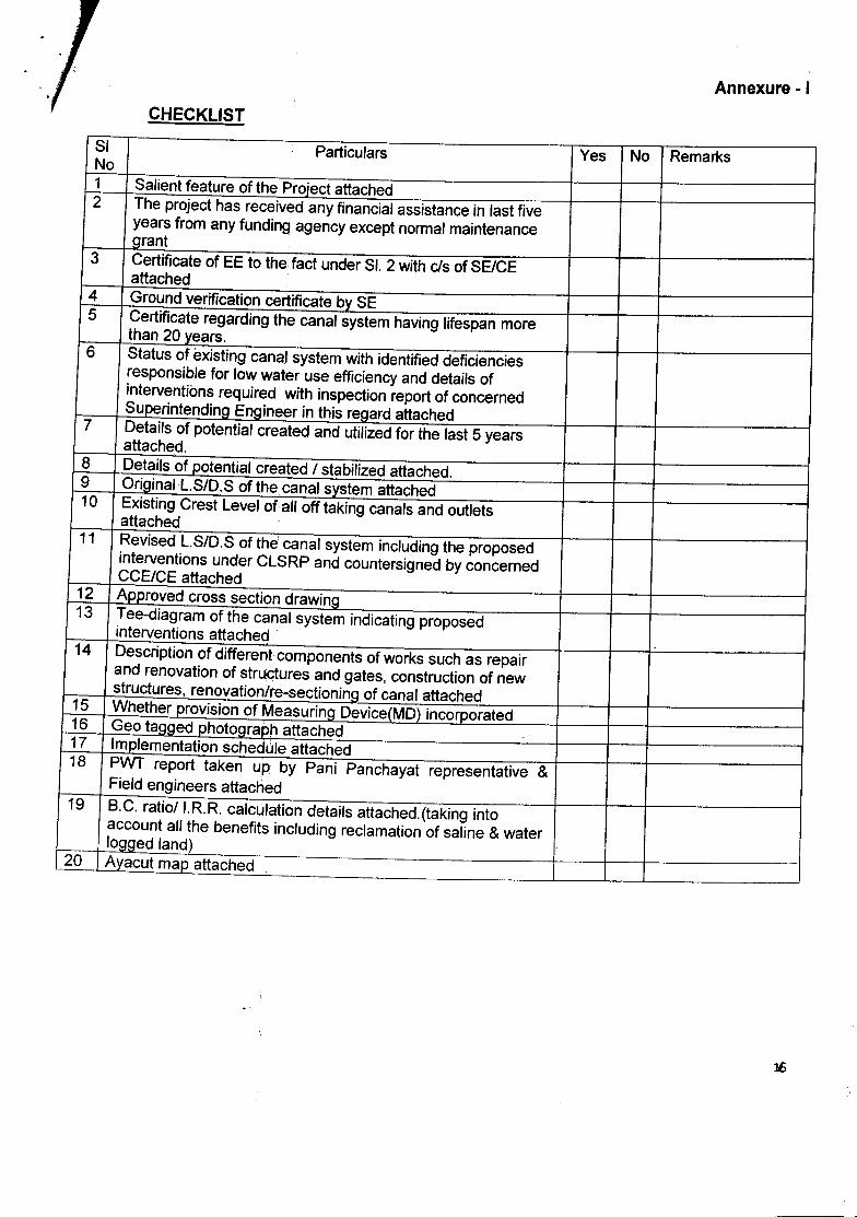
Annexure -ICHECKLIST
SI Particulars Yes No RemarksNo1 Salient feature of the Project attached2 The project has received any financial assistance in last five
years from any funding agency except normal maintenanceJ1!ant
3 Certificate of EE to the fact under SI. 2 with cis of SE/CEattached
4 Ground verification certificate by SE5 Certificate regarding the canal system having lifespan more
than 20_years.6 Status of eXisting canal system with identified deficiencies
responsible for low water use efficiency and details ofinterventions required with inspection report of concernedSl!e_erintendil}a El}aineer in this r~ard attached
7 Details of potential created and utilized for the last 5 yearsattached.
8 Details of potential created I stabilized attached.9 Or_!ginall.S/D.S of the-canal ~stem attached10 EXisting Crest Level of all off taking canals and outlets
attached11 Revised L.S/D.S of the canal system including the proposed
interventions under CLSRP and countersigned by concernedCCE/CE attached
12 J\pproved cross section drawir}9_13 Tee-diagram of the canal system indicating proposed
interventions attached14 Description of different components of works such as repair
and renovation of structures and gates, construction of newstructures, renovationlre-sectioning of canal attached
15 Whether __2rovisionof Measurif}9 Device_{MD)incorporated16 Geo tcmged phot~ra_Qh attached _-17 '1T!.2lementationschedule attached18 PWT report taken up by Pani Panchayat representative &
Field engineers attached19 B.C. ratioll.R.R. calculation details attached.(taking into
account all the benefits including reclamation of saline & waterlogged land)
20 l\Y_acutmap attached
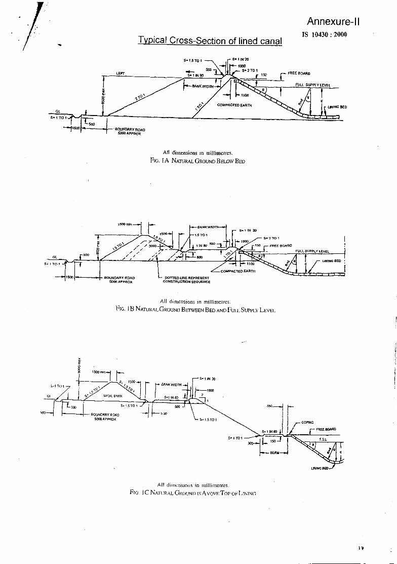
Typical Cross-Section of lined canal
Annexure-IIIS 10430; 2000
t
S-I.STO I
LEFT
COMPACTEDEARTH lINING BEDGl
r----4--·.BQUNOARY ROADSOOOAPPROX
All dimensions in millirnerres.FIG. IA NATURALGROUND BEWW BED
GL
DOTTED UNE REPRESENTCONSTRUCTION SEQUENCE
S... f TO t
All dimensions in millirnerres.PrG. I B NATURAL GROUND BETWEEN BED ANDFULL SUPPLY LEVEL
All dimensions in millirnetres.FIG. IC NATURAL GROUND ISAVOVETor OF LINING
I~

Annexure-III
Typical Cross-Section of lined canalrs 10430: 2000
LEFT BANK $-15T01
550-5-1 IHIO
",0',~
RIGHT BANK
All dimensions in millimetres.FIG. 2A NATURAL GROUND BELOWBED
LEFT BANK I--~OFCUPI SHAPEOCANAL
oorrso UNE .REPRESENTCONSTRUCTIC;N SEQUENCE
COMPACTED EARTH
RIGHT BANK
lINING
DonED LINE REPRESENT _.;'CONSTRUCTION SEQUENCE
All dimensions in millnuetrcsFIC; 28 NA1LiR"L GROUND BcrWEEN BEl) AND FULL SUPPLYLEVEL
.~
1
\'i
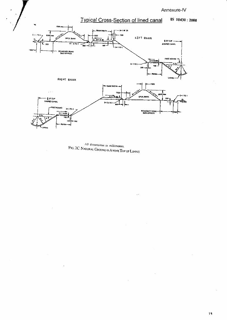
Annexure-IV
Typical Cross-Section of lined canal
RIGHT BANK
IS 10430: 2000
LEFT BANKtOFCUP :--l
SHAPED CANAL I
;---;,tOFCUPI _HAPiO CANAL'
[FREE BOARD· S-, TOt-S!1'N80 BO!J~OARYR:OAO -+ oJ·SOOOAPFROX
F Ail dimensions in Illillimel~esIG Ie N .
• - ATURAL GROUND ISA VOYE TopOF LINING
\'1

IS 10430: 2000Typical Cross-Section of lined canal
WIOI H -->.-....-lREFILLING UP, TO UNDER SIDEOF LINING WIlH SPAUS ANOCHiPS/LEAN CEMENT CONCRETE
REFilLING UP 10 UNDER SIDE Of LININGWITH ROCK SPOLLS ANOI CHIPS AVAILABLE .FROM CANAL CUllING ITVPi LEAN CEM£Nl
~ CONCRETE
:_\';) ace ..... ITHICK RANOI)I.t RUB8L( MASt:INRY IN CEMENT MonTARI I!' MIX WITH 20't. REPlACEMENT Of CEMEIIT BV FLY ASH
AND EXPOSED FACE PLAStEREO Will! 20 mm THICK CEMENTMORtAR I:L WflH ~O'l, REPLACEMENt OF CEMENT 9V FLYASH
PREsSURE REUEF VALVES 75 .... (JIA IN FILTERPOCKE TS PROVlOEO AT 10 000 mm CIC IN rwoROWS 1000 .... APART STAGGEREO (IYPICALI
PRESSURE RElIEF VALVEs 1S m m 01. IN FILTER POCKE rsPROVIDED Al 10000 mm ClC iN TWO ROWS 2000 mmAPAR! (STAGGEijEOJ
3A CAST-IN-SITU CEMENT CONCRETE liNING IN BED ANDRANDOM RUBBLE MASONRY LINING ON SlOES
100 Iftm THICK COPING·ICEMENTCONCRE IE M 100
h.P_O IM\ I HICK CoPINGIC£i.<ENT CONCRETE
M 100
Annexure-V \".,\\\
DETAil AT A
20..., THICK PLASTER litCEMENT MORlAR 1:4
/AANOOM RUBBLEMASONRV IN CEMEN!MORIAR H
I!Ef ILliltG UiI·.TOUHOE'RSI()£OF LINING WI!H ROCK SPAllSANO CHIPS AVAILABlE FROMCANAL CUllING LEAN/CEMENTCONCRETE crVPICALi
PRESSURE RELIEFVALVE ql15 rern
FILTERMATERIAL
J i'!\ 100 mm THI~~ CEMENT225 f-- CONCRE TE liNING {M.ISOI
IN aEC POROUS CONCRETEPRESSURE ~tLl€f VALVES 75 In" ()IA IN FitTERPOCKETS PROVIDEO AT 1000 """ ClC L"I TWOROW~ AI ENOS Of aEO ISTAGGEREDI
38 CAsT-IN-SITU CEMENI CONCRETE 1M-ISO) LINING IN·BED ANa RANDOM RUBBLE MASONRY 11I~INr. nN cmc e
FOUNDATIONCONCRETE" '5
100 mm THICKtitliNG IN CEMENTCONCREIE 1M1101
3C CASi-IN-SITU CEMENT CONCRETE1"1-150)LINING IIIBED .ANO RANDOM RUBBLE MASONRY LINING ON SIDES
NOTES1 In case of sound rock. cement concrete lining may be provided in bed and sides.On sides. the lining may be anchored suitably to the rock behind.2 All the dimensions are in millimetres unless otherwise specified.
FIG. 3 TYPICAL CROSS-SECTIONSOF LINED CANALS IN ROCK CuTT1NG
2.0

Annexure-VI
JOINTS
Joints shall be spaced and located as shown in the drawing or as directed by the
Engineer-in-charge. The grooves at the joints shall be of size and shape as shown on the
drawing and filled with hot applied sealing compound. Filling of the joint with hot applied sealing
compound should be taken up after completion of all other canal work. In the mean time the
grooves shall be filled with clean coarse sand.
Expansion Joints: Expansion joint shall not be provided except where structure intersect the
canal. At intersecting structures an expansion joint of 25 mm width filled with sealing compound
conforming to IS : 5256-1968 or with P.v.C. water stops shall be provided.
Construction Joint: Construction joints is placed at any location where it is suited as an
exigency to construction (interruption of work.). The construction joints are provided in the canal
lining, wherever there is discontinuity of concrete work for a period of time leading to creation of
cold joint. Generally, bed lining is executed in advance of the laying side lining. As such
construction joints are required on either side of canal bed at the junction of bed and side lining.
Normally longitudinal construction joints are provided at about 500 to 1000 mm from the tangent
point of the curve at the junction of canal bed and the side slope on either side of the bed. In the
case of small channels, where bed and side lining are laid simultaneously, longitudinal
construction joints are not provided. Transverse construction joints should be provided, where
discontinuity of work for considerable time is expected. 200 mm x 150 mm size CC M15grade
sleepers are provided under the construction joints. The joint should be filled with hot pour
sealing compound as per specifications in IS: 5256 - 1992.
SPECIFICATIONS OF SEALING COMPOUND FOR FILLING LONGITUDINAL AND TRANSVERSECONTRACTION JOINT GROOVES: The sealant is prepared fro~the materials as under:(i) Bitumen 85/25 55%(ii) S d fan (tineness modulus 1.0 to 1.5) 43%(iii) A bs estos powder 2%
Contraction joints :Contraction joints should be provided in canal lining at interval of not more
than 36 times the thickness of lining, in both longitudinal and 38 transverse directions. The
following spacing is adopted for different thicknesses of lining.
SI No. Spacing of contraction joint in MMThickness of lining in MM
2000602 75 2500
35004----r-------- ·---12-0----~-~---- r---~----------4c:-OO-:-O-·---·----~3 100