lineup of axial fans - omroncsm_r87f_r87t_ds_e_8_5 ac axial fans r87f/r87t optimum cooling with a...
TRANSCRIPT

1
CSM_R87F_R87T_DS_E_8_5
AC Axial Fans
R87F/R87TOptimum Cooling with a Comprehensive Lineup of Axial Fans• Low noise level, long service life, and resistance to the
environment.• Shaft supported by ball bearings for highly-reliable operation.• Plastic-bladed models (44 type) and metal-bladed models
(28 type) included in series.• R87T-A@A15H-WR Water-resistant AC Axial Fans
(IP X7 degree of protection) added to series.Note: The compliant standards and certified safety standards depend on the
product. Check the information in Characteristics.
Model Number StructureModel Number Legend
Note: 1. A Plug Cord (R87F-PC) is available as an option for models with terminals.2. These tables show only how to read product markings. They do not indicate which products are available. Refer to “Ratings and Ordering
Information” when ordering.
Ordering InformationAvailable ModelsAC Axial Fans Options (Order Separately)
Note: Mounting screws are not provided.
Safety PrecautionsRefer to the Safety Precautions for All Axial Fans on our website.
For the most recent information on models that have been certified for safety standards, refer to your OMRON website.
Refer to the Safety Precautions for All Axial Fans on our website.
1 2 3 4 5 6 7
9: 92 × 921: 120 × 1200: 150 dia.
3: 255: 387: 55
8
R87 -
1. Basic series
R87F: Plastic bladeR87T: Metal blade
2. Rated voltageA1: 100 VACA3: 115 VACA4: 200 VACA6: 230 VAC
3. Frame materialA: Die-cast aluminum
4. Frame size8: 80 × 80
5. Frame thickness
6. Rotational speed
H: HighM: MediumL: Low
7. Terminal type
No marking: Lead wiresP: Terminals (See note 1.)
-
8. TypeNo marking: Standard WR: Water-resistant
Series Size (mm) Model Datasheet available
R87F (plastic blades)
80 × 80 × t25 R87F-A@A83 Refer to page 2.
80 × 80 × t38 R87F-A@A85 Refer to page 4.
92 × 92 × t25 R87F-A@A93 Refer to page 6.
120 × 120 × t25 R87F-A@A13 Refer to page 8.
120 × 120 × t38 R87F-A@A15 Refer to page 10.
R87T (metal blades)
80 × 80 × t25 R87T-A@A83 Refer to page 12.
80 × 80 × t38 R87T-A@A85 Refer to page 14.
120 × 120 × t38 R87T-A@A15 Refer to page 16.
150-dia. × t38 R87T-A@A05 Refer to page 18.
150-dia. × t55 R87T-A@A07 Refer to page 20.
120 × 120 × t38 R87T-A@A15H-WR Refer to page 22.
Product name Model Datasheet available
Plug Cord R87F-PC Refer to page 24.
Finger Guard R87F-FG@ Refer to page 25.
Filter R87F-FL@(S) Refer to page 26.

2
AC Axial Fans with Lead Wires (80 × 80 × t25 mm)
R87F-A@A83SpecificationsRatings and Ordering InformationNote: An asterisk (*) indicates a nominal value.
Characteristics
ItemRated
voltage(V)
Permittedvoltage
fluctuationrange (%)
Frequency(Hz)
Rated current (A) *
Rated input (W) *
Rated rotational
speed (r/min) *
Maximum flow rate
(m3/min) *
Maximum static
pressure (Pa) *
Noise (dB) *
Model 50 Hz 60 Hz 50 Hz 60 Hz 50 Hz 60 Hz 50 Hz 60 Hz 50 Hz 60 Hz 50 Hz 60 HzR87F-A1A83H 100 VAC
85% to 110% rated voltage 50/60
0.097 0.080
7 6 2,600 3,000 0.6 0.7 39.2 53.9 32 36R87F-A3A83H 115 VAC 0.085 0.070
R87F-A4A83H 200 VAC 0.048 0.041
R87F-A6A83H 230 VAC 0.046 0.039
R87F-A1A83L 100 VAC
85% to 110% rated voltage 50/60
0.063 0.055
5 4 1,900 2,100 0.4 0.5 19.5 23.5 28 30R87F-A3A83L 115 VAC 0.055 0.048
R87F-A4A83L 200 VAC 0.033 0.030
R87F-A6A83L 230 VAC 0.028 0.024
Motor type Single-phase shading coil induction motor (2-pole, open type)
Terminal type Lead wires
Insulation classIEC class B (130°C)UL class A (105°C)CSA class A (105°C)
Insulation resistance 100 MΩ min. (at 500 VDC) between all power supply connections and uncharged metal parts.
Insulation withstand voltage 2,000 VAC (1 minute) between all power supply connections and uncharged metal parts.
Ambient operating temperature −30 to 70°C (no icing)
Ambient storage temperature −40 to 85°C (no icing)
Ambient humidity 25% to 85%
Protection Impedance protection
Materials Frame: Die-cast aluminum Blades: Glass polycarbonate
Bearings Ball bearings
Weight Approx. 230 g
Compliant standards EN/IEC 60335 (CE marking compliant)
Certified standards UL/CSA
3
R87F/R87T
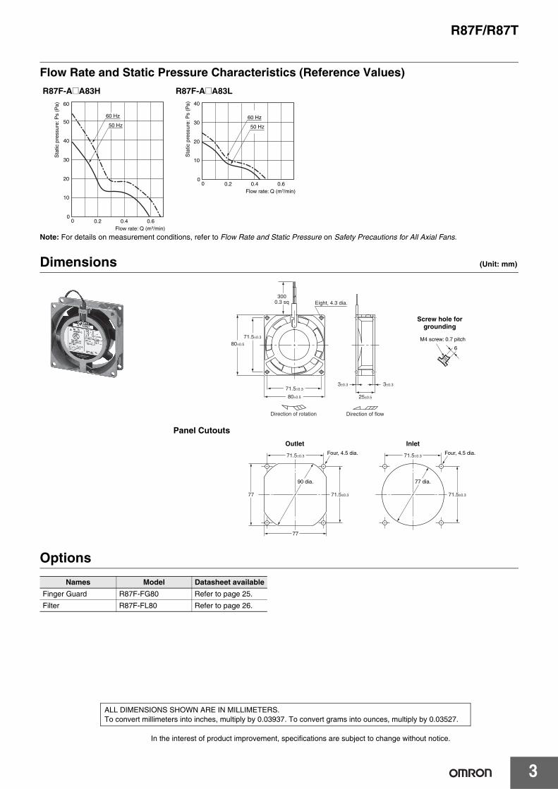
Flow Rate and Static Pressure Characteristics (Reference Values)
Note: For details on measurement conditions, refer to Flow Rate and Static Pressure on Safety Precautions for All Axial Fans.
Dimensions (Unit: mm)
Panel Cutouts
Options
R87F-A@A15
R87F-A@A83H R87F-A@A83L
Names Model Datasheet availableFinger Guard R87F-FG80 Refer to page 25.
Filter R87F-FL80 Refer to page 26.
60 Hz
50 Hz
Sta
tic p
ress
ure:
Ps
(Pa)
Flow rate: Q (m3/min)
10
20
30
40
50
60
00 0.2 0.4 0.6
Sta
tic p
ress
ure:
Ps
(Pa)
Flow rate: Q (m3/min)
10
20
30
40
00 0.2 0.4 0.6
60 Hz
50 Hz
3±0.33±0.3
Eight, 4.3 dia.
71.5±0.3
80±0.5
71.5±0.3
80±0.5
3000.3 sq
25±0.5
Direction of flowDirection of rotation
6
M4 screw: 0.7 pitch
Screw hole for grounding
Four, 4.5 dia. Four, 4.5 dia.
71.5±0.377 71.5±0.3
71.5±0.3
77
71.5±0.3
90 dia. 77 dia.
Outlet Inlet
In the interest of product improvement, specifications are subject to change without notice.
ALL DIMENSIONS SHOWN ARE IN MILLIMETERS.To convert millimeters into inches, multiply by 0.03937. To convert grams into ounces, multiply by 0.03527.

4
AC Axial Fans with Terminals (80 × 80 × t38 mm)
R87F-A@A85SpecificationsRatings and Ordering InformationNote: An asterisk (*) indicates a nominal value.
Characteristics
ItemRated
voltage(V)
Permittedvoltage
fluctuationrange (%)
Frequency(Hz)
Rated current (A) *
Rated input (W) *
Rated rotational
speed (r/min) *
Maximum flow rate
(m3/min) *
Maximum static
pressure (Pa) *
Noise (dB) *
Model 50 Hz 60 Hz 50 Hz 60 Hz 50 Hz 60 Hz 50 Hz 60 Hz 50 Hz 60 Hz 50 Hz 60 HzR87F-A1A85HP 100 VAC
85% to 110% rated voltage
50/60
0.140 0.115
10 9 2,700 3,200 0.8 0.9 42.1 58.8 32 36R87F-A3A85HP 115 VAC 0.120 0.100
R87F-A4A85HP 200 VAC 0.080 0.060
R87F-A6A85HP 230 VAC 0.060 0.050
R87F-A1A85LP 100 VAC85% to 110% rated voltage
50/60
0.090 0.080
7 6 2,200 2,500 0.6 0.7 25.0 32.0 26 29R87F-A3A85LP 115 VAC 0.080 0.070
R87F-A4A85LP 200 VAC 0.050 0.040
R87F-A6A85LP 230 VAC 0.040 0.040
Motor type Single-phase shading coil induction motor (2-pole, open type)
Terminal type Terminals
Insulation classIEC class B (130°C)UL class A (105°C)CSA class A (105°C)
Insulation resistance 100 MΩ min. (at 500 VDC) between all power supply connections and uncharged metal parts.
Insulation withstand voltage 2,000 VAC (1 minute) between all power supply connections and uncharged metal parts.
Ambient operating temperature −30 to 70°C (no icing)
Ambient storage temperature −40 to 85°C (no icing)
Ambient humidity 25% to 85%
Protection Impedance protection
Materials Frame: Die-cast aluminum Blades: Glass polycarbonate
Bearings Ball bearings
Weight Approx. 280 g
Compliant standards PSE, EN/IEC 60335 (CE marking compliant)
Certified standards UL/CSA

5
R87F/R87T
Flow Rate and Static Pressure Characteristics (Reference Values)
Note: For details on measurement conditions, refer to Flow Rate and Static Pressure on Safety Precautions for All Axial Fans.
Dimensions (Unit: mm)
Panel Cutouts
Options
R87F-A@A85HP R87F-A@A85LP
Name Model Datasheet availablePlug Cord R87F-PC Refer to page 24.
Finger Guard R87F-FG80 Refer to page 25.
Filter R87F-FL80 Refer to page 26.
10
20
30
40
50
60
00 0.2 0.4 0.6 0.8 1.0
Sta
tic p
ress
ure:
Ps
(Pa)
Flow rate: Q (m3 /min)
60 Hz
50 Hz
0.25 0.5 0.75 1
88.3
78.5
68.6
58.8
49.0
39.2
29.4
19.6
9.8
0
60 Hz
50 HzS
tatic
pre
ssur
e: P
s (P
a)
Flow rate: Q (m3 /min)
Direction of rotation
Eight, 4.3 dia.
71.5±0.3
80±0.5
3±0.3 3±0.371.5±0.3
80±0.5 38±0.5
Direction of flow
5.8
M4 screw: 0.7 pitch
8 2.8
Screw hole for grounding
Terminal shape
Faston #110 terminal(or equivalent)
Four, 4.5 dia. Four, 4.5 dia.
71.5±0.377 71.5±0.3
71.5±0.3
77
71.5±0.3
90 dia. 77 dia.
Outlet Inlet
In the interest of product improvement, specifications are subject to change without notice.
ALL DIMENSIONS SHOWN ARE IN MILLIMETERS.To convert millimeters into inches, multiply by 0.03937. To convert grams into ounces, multiply by 0.03527.
6
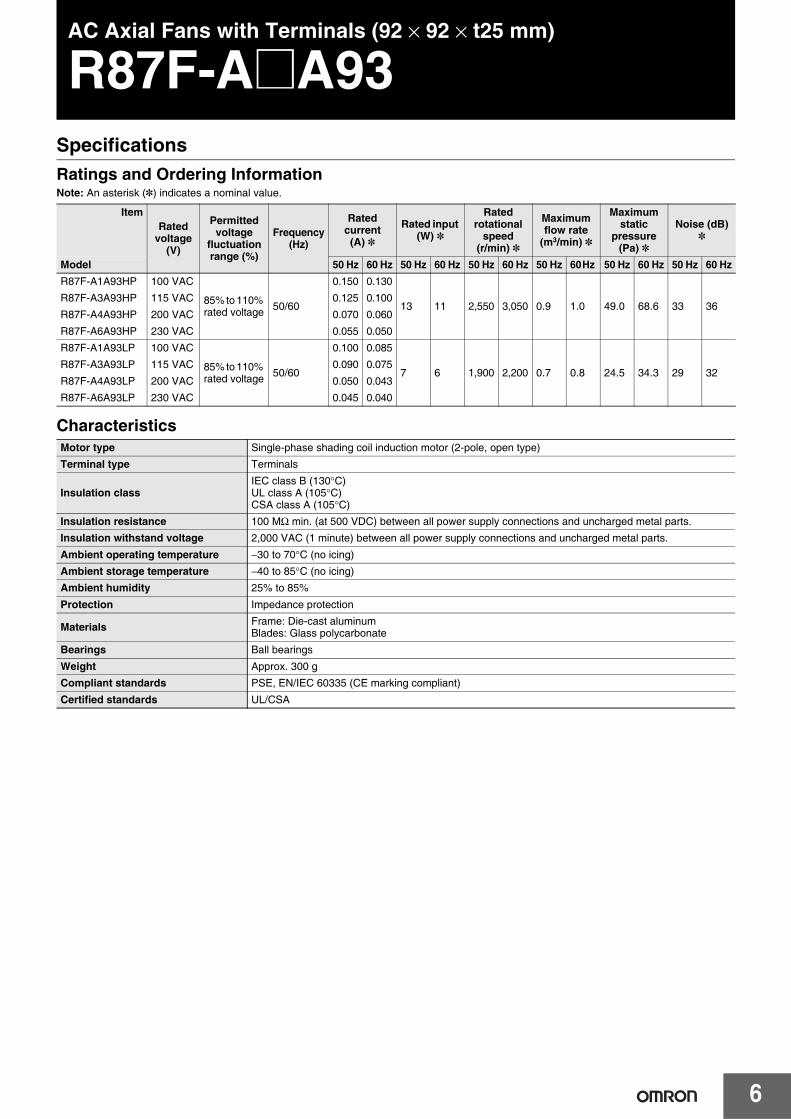
AC Axial Fans with Terminals (92 × 92 × t25 mm)
R87F-A@A93SpecificationsRatings and Ordering InformationNote: An asterisk (*) indicates a nominal value.
Characteristics
ItemRated
voltage(V)
Permittedvoltage
fluctuationrange (%)
Frequency(Hz)
Rated current (A) *
Rated input (W) *
Rated rotational
speed (r/min) *
Maximum flow rate
(m3/min) *
Maximum static
pressure (Pa) *
Noise (dB) *
Model 50 Hz 60 Hz 50 Hz 60 Hz 50 Hz 60 Hz 50 Hz 60 Hz 50 Hz 60 Hz 50 Hz 60 HzR87F-A1A93HP 100 VAC
85% to 110% rated voltage 50/60
0.150 0.130
13 11 2,550 3,050 0.9 1.0 49.0 68.6 33 36R87F-A3A93HP 115 VAC 0.125 0.100
R87F-A4A93HP 200 VAC 0.070 0.060
R87F-A6A93HP 230 VAC 0.055 0.050
R87F-A1A93LP 100 VAC
85% to 110% rated voltage 50/60
0.100 0.085
7 6 1,900 2,200 0.7 0.8 24.5 34.3 29 32R87F-A3A93LP 115 VAC 0.090 0.075
R87F-A4A93LP 200 VAC 0.050 0.043
R87F-A6A93LP 230 VAC 0.045 0.040
Motor type Single-phase shading coil induction motor (2-pole, open type)
Terminal type Terminals
Insulation classIEC class B (130°C)UL class A (105°C)CSA class A (105°C)
Insulation resistance 100 MΩ min. (at 500 VDC) between all power supply connections and uncharged metal parts.
Insulation withstand voltage 2,000 VAC (1 minute) between all power supply connections and uncharged metal parts.
Ambient operating temperature −30 to 70°C (no icing)
Ambient storage temperature −40 to 85°C (no icing)
Ambient humidity 25% to 85%
Protection Impedance protection
Materials Frame: Die-cast aluminum Blades: Glass polycarbonate
Bearings Ball bearings
Weight Approx. 300 g
Compliant standards PSE, EN/IEC 60335 (CE marking compliant)
Certified standards UL/CSA

7
R87F/R87T
Flow Rate and Static Pressure Characteristics (Reference Values)v
Note: For details on measurement conditions, refer to Flow Rate and Static Pressure on Safety Precautions for All Axial Fans.
Dimensions (Unit: mm)c
Options
R87F-A@A93HP R87F-A@A93LP
Name Model Datasheet availablePlug Cord R87F-PC Refer to page 24.
Finger Guard R87F-FG90 Refer to page 25.
Filter R87F-FL90 Refer to page 26.
Sta
tic p
ress
ure:
Ps
(Pa)
Flow rate: Q (m3/min)
60 Hz
50 Hz
10
20
30
40
50
60
70
00 0.2 0.4 0.6 0.8 1.0
60 Hz
50 Hz
10
20
30
50
40
00 0.2 0.4 0.6 0.8 1.0
Sta
tic p
ress
ure:
Ps
(Pa)
Flow rate: Q (m3/min)
7.8
M4 screw: 0.7 pitch
9
2.8
Six, 4.3 dia.
Two, 3.2±0.15 dia.
4±0.34±0.3
25±0.5
92±0.5
82.5±0.3
92±0.5
82.5±0.3
Direction of flowDirection of rotation
Screw hole for grounding
Terminal shape
Faston #110 terminal(or equivalent)
Four, 4.5 dia. Four, 4.5 dia.82.5±0.3
89
82.5±0.3
82.5±0.3 82.5±0.389
98 dia. 89 dia.
Outlet Inlet
Panel cutting reference dimensions (note 3 mounting holes)
Panel Cutouts
In the interest of product improvement, specifications are subject to change without notice.
ALL DIMENSIONS SHOWN ARE IN MILLIMETERS.To convert millimeters into inches, multiply by 0.03937. To convert grams into ounces, multiply by 0.03527.
8
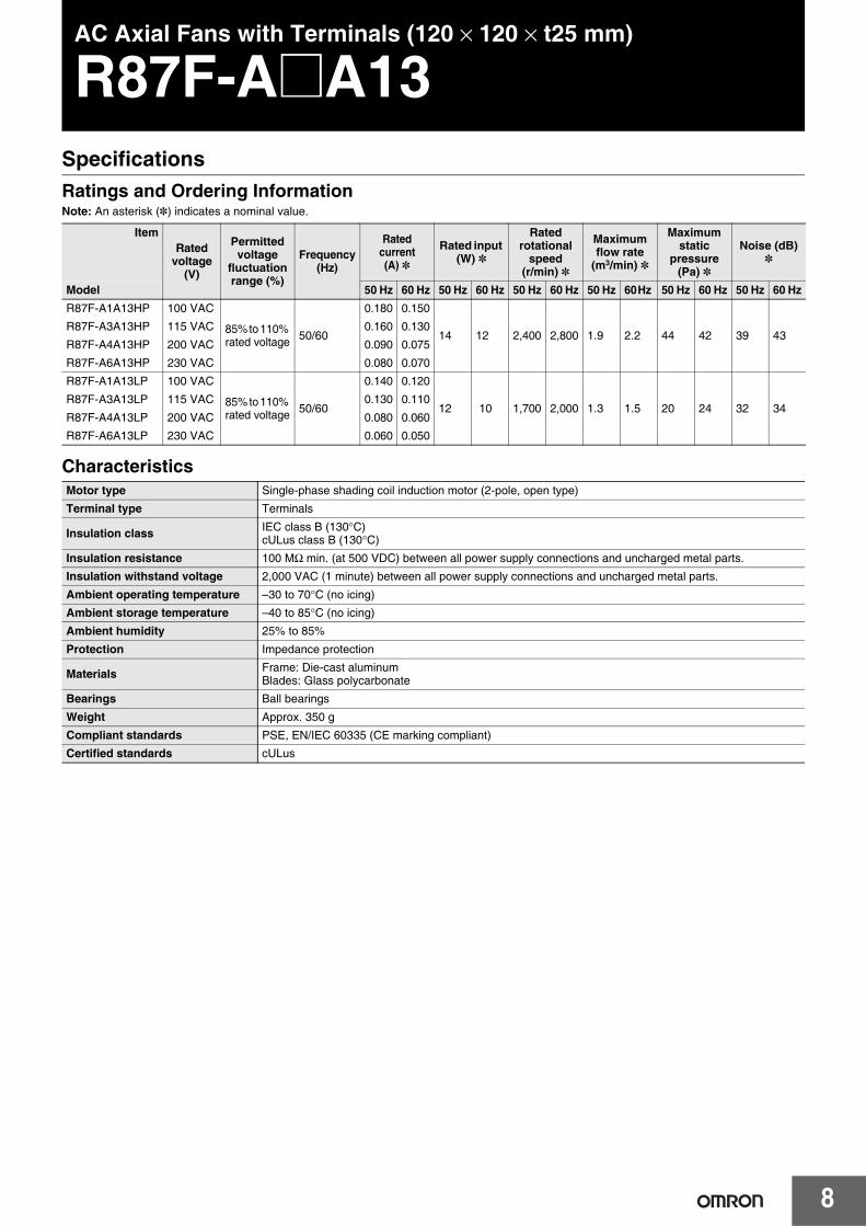
AC Axial Fans with Terminals (120 × 120 × t25 mm)
R87F-A@A13SpecificationsRatings and Ordering InformationNote: An asterisk (*) indicates a nominal value.
Characteristics
ItemRated
voltage(V)
Permittedvoltage
fluctuationrange (%)
Frequency(Hz)
Rated current (A) *
Rated input (W) *
Rated rotational
speed (r/min) *
Maximum flow rate
(m3/min) *
Maximum static
pressure (Pa) *
Noise (dB) *
Model 50 Hz 60 Hz 50 Hz 60 Hz 50 Hz 60 Hz 50 Hz 60 Hz 50 Hz 60 Hz 50 Hz 60 HzR87F-A1A13HP 100 VAC
85% to 110% rated voltage 50/60
0.180 0.150
14 12 2,400 2,800 1.9 2.2 44 42 39 43R87F-A3A13HP 115 VAC 0.160 0.130
R87F-A4A13HP 200 VAC 0.090 0.075
R87F-A6A13HP 230 VAC 0.080 0.070
R87F-A1A13LP 100 VAC
85% to 110% rated voltage 50/60
0.140 0.120
12 10 1,700 2,000 1.3 1.5 20 24 32 34R87F-A3A13LP 115 VAC 0.130 0.110
R87F-A4A13LP 200 VAC 0.080 0.060
R87F-A6A13LP 230 VAC 0.060 0.050
Motor type Single-phase shading coil induction motor (2-pole, open type)
Terminal type Terminals
Insulation class IEC class B (130°C)cULus class B (130°C)
Insulation resistance 100 MΩ min. (at 500 VDC) between all power supply connections and uncharged metal parts.
Insulation withstand voltage 2,000 VAC (1 minute) between all power supply connections and uncharged metal parts.
Ambient operating temperature –30 to 70°C (no icing)
Ambient storage temperature –40 to 85°C (no icing)
Ambient humidity 25% to 85%
Protection Impedance protection
Materials Frame: Die-cast aluminum Blades: Glass polycarbonate
Bearings Ball bearings
Weight Approx. 350 g
Compliant standards PSE, EN/IEC 60335 (CE marking compliant)
Certified standards cULus
9
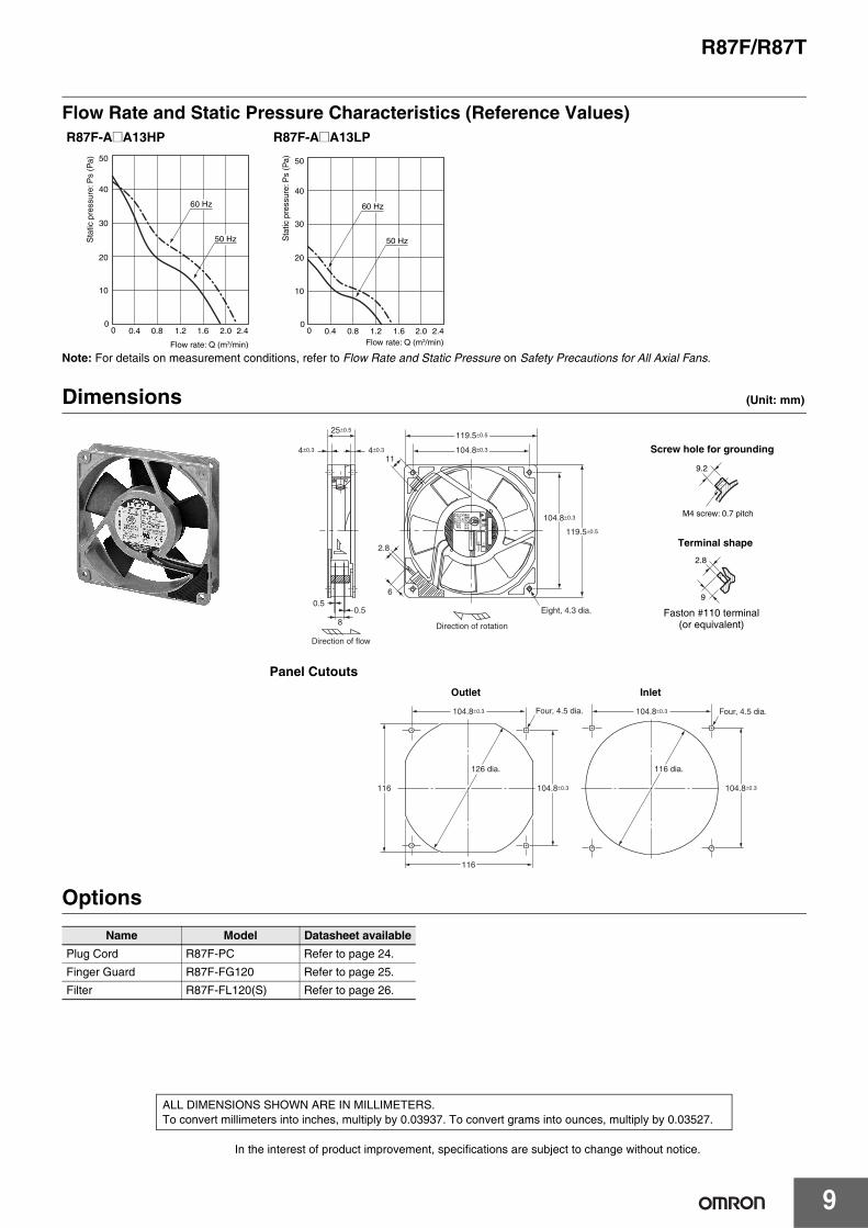
R87F/R87T
Flow Rate and Static Pressure Characteristics (Reference Values)
Note: For details on measurement conditions, refer to Flow Rate and Static Pressure on Safety Precautions for All Axial Fans.
Dimensions (Unit: mm)
Panel Cutouts
Options
R87F-A@A13HP R87F-A@A13LP
Name Model Datasheet availablePlug Cord R87F-PC Refer to page 24.
Finger Guard R87F-FG120 Refer to page 25.
Filter R87F-FL120(S) Refer to page 26.
60 Hz
50 Hz
50
40
30
20
10
00 0.4 0.8 1.2 1.6 2.0 2.4
Sta
tic p
ress
ure:
Ps
(Pa)
Flow rate: Q (m3/min)
60 Hz
50 Hz
10
20
30
40
50
00 0.4 0.8 1.2 1.6 2.0 2.4
Sta
tic p
ress
ure:
Ps
(Pa)
Flow rate: Q (m3/min)
Eight, 4.3 dia.
Direction of flow
Direction of rotation
0.50.5
104.8±0.3
119.5±0.5
104.8±0.3
119.5±0.5
8
4±0.34±0.3
25±0.5
6
11
2.8
9.2
M4 screw: 0.7 pitch
9
2.8
Screw hole for grounding
Terminal shape
Faston #110 terminal(or equivalent)
Four, 4.5 dia. Four, 4.5 dia.104.8±0.3
104.8±0.3
116
104.8±0.3
116 104.8±0.3
126 dia. 116 dia.
Outlet Inlet
In the interest of product improvement, specifications are subject to change without notice.
ALL DIMENSIONS SHOWN ARE IN MILLIMETERS.To convert millimeters into inches, multiply by 0.03937. To convert grams into ounces, multiply by 0.03527.

10
AC Axial Fans with Terminals (120 × 120 × t38 mm)
R87F-A@A15SpecificationsRatings and Ordering InformationNote: An asterisk (*) indicates a nominal value.
Characteristics
ItemRated
voltage (V)
Permittedvoltage
fluctuationrange (%)
Frequency(Hz)
Rated current (A) *
Rated input (W) *
Rated rotational
speed (r/min) *
Maximum flow rate
(m3/min) *
Maximum static
pressure (Pa) *
Noise (dB) *
Model 50 Hz 60 Hz 50 Hz 60 Hz 50 Hz 60 Hz 50 Hz 60 Hz 50 Hz 60 Hz 50 Hz 60 HzR87F-A1A15HP 100 VAC
85% to 110%rated voltage 50/60
0.230 0.200
15 14 2,750 3,200 2.7 3.1 93 80 42 46R87F-A3A15HP 115 VAC 0.190 0.170
R87F-A4A15HP 200 VAC 0.110 0.100
R87F-A6A15HP 230 VAC 0.090 0.080
R87F-A1A15MP 100 VAC
85% to 110%rated voltage 50/60
0.220 0.180
15 14 2,450 2,700 2.2 2.5 64 64 39 42R87F-A3A15MP 115 VAC 0.180 0.160
R87F-A4A15MP 200 VAC 0.110 0.090
R87F-A6A15MP 230 VAC 0.090 0.080
R87F-A1A15LP 100 VAC
85% to 110%rated voltage 50/60
0.170 0.150
11 10 2,100 2,250 2.0 2.1 44 44 36 38R87F-A3A15LP 115 VAC 0.140 0.120
R87F-A4A15LP 200 VAC 0.080 0.070
R87F-A6A15LP 230 VAC 0.070 0.060
Motor type Single-phase shading coil induction motor (2-pole, open type)
Terminal type Terminals
Insulation class IEC class B (130°C)cULus class B (130°C)
Insulation resistance 100 MΩ min. (at 500 VDC) between all power supply connections and uncharged metal parts.
Insulation withstand voltage 2,000 VAC (1 minute) between all power supply connections and uncharged metal parts.
Ambient operating temperature −30 to 70°C (no icing)
Ambient storage temperature −40 to 85°C (no icing)
Ambient humidity 25% to 85%
Protection Impedance protection
Materials Frame: Die-cast aluminum Blades: Glass polycarbonate
Bearings Ball bearings
Weight Approx. 540 g
Compliant standards PSE, EN/IEC 60335 (CE marking compliant)
Certified standards cULus

11
R87F/R87T
Flow Rate and Static Pressure Characteristics (Reference Values)
Note: For details on measurement conditions, refer to Flow Rate and Static Pressure on Safety Precautions for All Axial Fans.
Dimensions (Unit: mm)
Panel Cutouts
Options
R87F-A@A15HP R87F-A@A15MP R87F-A@A15LP
Name Model Datasheet availablePlug Cord R87F-PC Refer to page 24.
Finger Guard R87F-FG120 Refer to page 25.
Filter R87F-FL120(S) Refer to page 26.
100
80
60
40
20
Sta
tic p
ress
ure:
Ps
(Pa)
0 0.8 1.6 2.4 3.2Flow rate: Q (m3/min)
60Hz
50Hz
100
80
60
40
20
0 0.8 1.6 2.4 3.2
60 Hz
50 HzS
tatic
pre
ssur
e: P
s (P
a)
Flow rate: Q (m3/min)
60 Hz
50 Hz
100
80
60
40
20
0 0.8 1.6 2.4 3.2
Sta
tic p
ress
ure:
Ps
(Pa)
Flow rate: Q (m3/min)
11
M4 screw: 0.7 pitch
9
2.8
104.8±0.3
104.8±0.3
119.5±0.538±0.5
119.5±0.5
4±0.3 4±0.3
9
2.8
8
0.50.5 11
Direction of flow Direction of rotation
Eight, 4.3 dia.Screw hole for grounding
Terminal shape
Faston #110 terminals(or equivalent)
Four, 4.5 dia. Four, 4.5 dia.104.8±0.3 104.8±0.3
104.8±0.3104.8±0.3116
116
126 dia. 116 dia.
Outlet Inlet
In the interest of product improvement, specifications are subject to change without notice.
ALL DIMENSIONS SHOWN ARE IN MILLIMETERS.To convert millimeters into inches, multiply by 0.03937. To convert grams into ounces, multiply by 0.03527.

12
AC Axial Fans with Lead Wires (80 × 80 × t25 mm)
R87T-A@A83SpecificationsRatings and Ordering InformationNote: An asterisk (*) indicates a nominal value.
Characteristics
ItemRated
voltage(V)
Permittedvoltage
fluctuationrange (%)
Frequency(Hz)
Rated current
(A)*
Rated input (W)*
Rated rotational
speed (r/min)*
Maximum flow rate (m3/min)*
Maximum static
pressure (Pa)*
Noise (dB)*
Model 50 Hz 60 Hz 50 Hz 60 Hz 50 Hz 60 Hz 50 Hz 60 Hz 50 Hz 60 Hz 50 Hz 60 HzR87T-A1A83H 100 VAC
85% to 110% rated voltage 50/60
0.180 0.150
12 11 2,500 3,000 0.5 0.6 34.0 49.0 33 36R87T-A3A83H 115 VAC 0.150 0.130
R87T-A4A83H 200 VAC 0.087 0.075
R87T-A6A83H 230 VAC 0.075 0.065
Motor type Single-phase shading coil induction motor (2-pole, open type)
Terminal type Lead wires
Insulation class IEC class B (130°C)UL class A (105°C)
Insulation resistance 100 MΩ min. (at 500 VDC) between all power supply connections and uncharged metal parts.
Insulation withstand voltage 2,000 VAC (1 minute) between all power supply connections and uncharged metal parts.
Ambient operating temperature −20 to 70°C (no icing)
Ambient storage temperature −40 to 85°C (no icing)
Ambient humidity 25% to 85%
Protection Impedance protection
Materials Frame Die-cast aluminum
Blades Steel plate (black coating)
Bearings Ball bearings
Weight Approx. 330 g
Standards EN/IEC 60335 (CE marking compliant)
Certified standards UL

13
R87F/R87T
Flow Rate and Static Pressure Characteristics (Reference Values)
Note: For details on measurement conditions, refer to Flow Rate and Static Pressure on Safety Precautions for All Axial Fans.
Dimensions (Unit: mm)
Panel Cutouts
Options
R87T-A@A83H
Name Model Datasheet availableFinger Guard R87F-FG80 Refer to page 25.
Filter R87F-FL80 Refer to page 26.
Sta
tic p
ress
ure:
Ps
(Pa)
Flow rate: Q (m3/min)
60 Hz
50 Hz
10
20
30
40
50
00 0.2 0.4 0.6
Direction of flowDirection of rotation
Eight, 4.5 dia.300
0.3 sq
71.5±0.3
80±0.5
71.5±0.3
80±0.5
26.5 max.
3±0.3 3±0.3
25±0.5
M4 screw: 0.7 pitch
5.5
Screw hole for grounding
Four, 4.5 dia. Four, 4.5 dia.
71.5±0.377 71.5±0.3
71.5±0.3
77
71.5±0.3
90 dia. 77 dia.
Outlet Inlet
In the interest of product improvement, specifications are subject to change without notice.
ALL DIMENSIONS SHOWN ARE IN MILLIMETERS.To convert millimeters into inches, multiply by 0.03937. To convert grams into ounces, multiply by 0.03527.

14
AC Axial Fans with Lead Wires (80 × 80 × t38 mm)
R87T-A@A85SpecificationsRatings and Ordering InformationNote: An asterisk (*) indicates a nominal value.
Characteristics
ItemRated
voltage(V)
Permittedvoltage
fluctuationrange (%)
Frequency(Hz)
Rated current (A) *
Rated input (W) *
Rated rotational
speed (r/min) *
Maximum flow rate
(m3/min) *
Maximum static
pressure (Pa) *
Noise (dB) *
Model 50 Hz 60 Hz 50 Hz 60 Hz 50 Hz 60 Hz 50 Hz 60 Hz 50 Hz 60 Hz 50 Hz 60 HzR87T-A1A85H 100 VAC
85% to 110% rated voltage 50/60
0.180 0.160
12 10 2,800 3,300 0.80 0.90 42 58 37 40R87T-A3A85H 115 VAC 0.155 0.135
R87T-A4A85H 200 VAC 0.085 0.075
R87T-A6A85H 230 VAC 0.080 0.070
Motor type Single-phase shading coil induction motor (2-pole, open type)
Terminal type Lead wires
Insulation class IEC class B (130°C)UL class A (105°C)
Insulation resistance 100 MΩ min. (at 500 VDC) between all power supply connections and uncharged metal parts.
Insulation withstand voltage 2,000 VAC (1 minute) between all power supply connections and uncharged metal parts.
Ambient operating temperature −20 to 70°C (no icing)
Ambient storage temperature −40 to 85°C (no icing)
Ambient humidity 25% to 85%
Protection Impedance protection
Materials Frame: Die-cast aluminum Blades: Steel plate (black coating)
Bearings Ball bearings
Weight Approx. 440 g
Compliant standards EN/IEC 60335 (CE marking compliant)
Certified standards UL

15
R87F/R87T
Flow Rate and Static Pressure Characteristics (Reference Values)
Note: For details on measurement conditions, refer to Flow Rate and Static Pressure on Safety Precautions for All Axial Fans.
Dimensions (Unit: mm)
Panel Cutouts
Options
R87T-A@A85H
Name Model Datasheet availableFinger Guard R87F-FG80 Refer to page 25.
Filter R87F-FL80 Refer to page 26.
Sta
tic p
ress
ure:
Ps
(Pa)
Flow rate: Q (m3/min)
60 Hz
50 Hz
10
20
30
40
50
60
00 0.2 0.4 0.6 0.8 1.0
Direction of flow
Eight, 4.5 dia.
71.5±0.3
71.5±0.3
80±0.5
3±0.3 3±0.3
38±0.580±0.5
3000.3 sq
Direction of rotation
5.8
M4 screw: 0.7 pitch
Screw hole for grounding
Four, 4.5 dia. Four, 4.5 dia.
71.5±0.377 71.5±0.3
71.5±0.3
77
71.5±0.3
90 dia. 77 dia.
Outlet Inlet
In the interest of product improvement, specifications are subject to change without notice.
ALL DIMENSIONS SHOWN ARE IN MILLIMETERS.To convert millimeters into inches, multiply by 0.03937. To convert grams into ounces, multiply by 0.03527.

16
AC Axial Fans with Terminals (120 × 120 × t38 mm)
R87T-A@A15SpecificationsRatings and Ordering InformationNote: An asterisk (*) indicates a nominal value.
Characteristics
ItemRated
voltage(V)
Permittedvoltage
fluctuationrange (%)
Frequency(Hz)
Rated current (A) *
Rated input (W) *
Rated rotational
speed (r/min) *
Maximum flow rate
(m3/min) *
Maximum static
pressure (Pa) *
Noise (dB) *
Model 50 Hz 60 Hz 50 Hz 60 Hz 50 Hz 60 Hz 50 Hz 60 Hz 50 Hz 60 Hz 50 Hz 60 HzR87T-A1A15HP 100 VAC
85% to 110% rated voltage 50/60
0.240 0.210
17 16 2,700 3,100 2.6 2.9 80 62 42 46R87T-A3A15HP 115 VAC 0.210 0.180
R87T-A4A15HP 200 VAC 0.120 0.110
R87T-A6A15HP 230 VAC 0.110 0.090
R87T-A1A15MP 100 VAC
85% to 110% rated voltage 50/60
0.170 0.150
12 11 2,350 2,600 1.8 2.1 42 40 36 40R87T-A3A15MP 115 VAC 0.140 0.120
R87T-A4A15MP 200 VAC 0.080 0.070
R87T-A6A15MP 230 VAC 0.070 0.060
Motor type Single-phase shading coil induction motor (2-pole, open type)
Terminal type Terminals
Insulation class IEC class B (130°C)cULus class B (130°C)
Insulation resistance 100 MΩ min. (at 500 VDC) between all power supply connections and uncharged metal parts.
Insulation withstand voltage 2,000 VAC (1 minute) between all power supply connections and uncharged metal parts.
Ambient operating temperature −20 to 70°C (no icing)
Ambient storage temperature −40 to 85°C (no icing)
Ambient humidity 25% to 85%
Protection Impedance protection
Materials Frame: Die-cast aluminum Blades: Steel plate (black coating)
Bearings Ball bearings
Weight Approx. 540 g
Compliant standards PSE, EN/IEC 60335 (CE marking compliant)
Certified standards cULus

17
R87F/R87T
Flow Rate and Static Pressure Characteristics (Reference Values)v
Note: For details on measurement conditions, refer to Flow Rate and Static Pressure on Safety Precautions for All Axial Fans.
Dimensions (Unit: mm)
Panel Cutouts
Options
R87T-A@A15HP R87T-A@A15MP
Name Model Datasheet availablePlug Cord R87F-PC Refer to page 24.
Finger Guard R87F-FG120 Refer to page 25.
Filter R87F-FL120(S) Refer to page 26.
Sta
tic p
ress
ure:
Ps
(Pa)
Flow rate: Q (m3/min)
60
80
100
0
20
40
0.5 2.5 321.51
50 Hz60 Hz
Sta
tic p
ress
ure:
Ps
(Pa)
Flow rate: Q (m3/min)
20
40
60
80
100
00.5 1 1.5 2 2.5 3
50 Hz60 Hz
Direction of rotation
Eight, 4.3 dia.
Direction of flow
104.8±0.3
119.5±0.5
119.5±0.5
104.8±0.3
11
2.8
9
8
0.50.5
4±0.34±0.3
38±0.5
11
M4 screw: 0.7 pitch
9 2.8
Screw hole for grounding
Terminal shape
Faston #110 terminal(or equivalent)
Four, 4.5 dia. Four, 4.5 dia.104.8±0.3
104.8±0.3
116
104.8±0.3
116 104.8±0.3
126 dia. 116 dia.
Outlet Inlet
In the interest of product improvement, specifications are subject to change without notice.
ALL DIMENSIONS SHOWN ARE IN MILLIMETERS.To convert millimeters into inches, multiply by 0.03937. To convert grams into ounces, multiply by 0.03527.
18
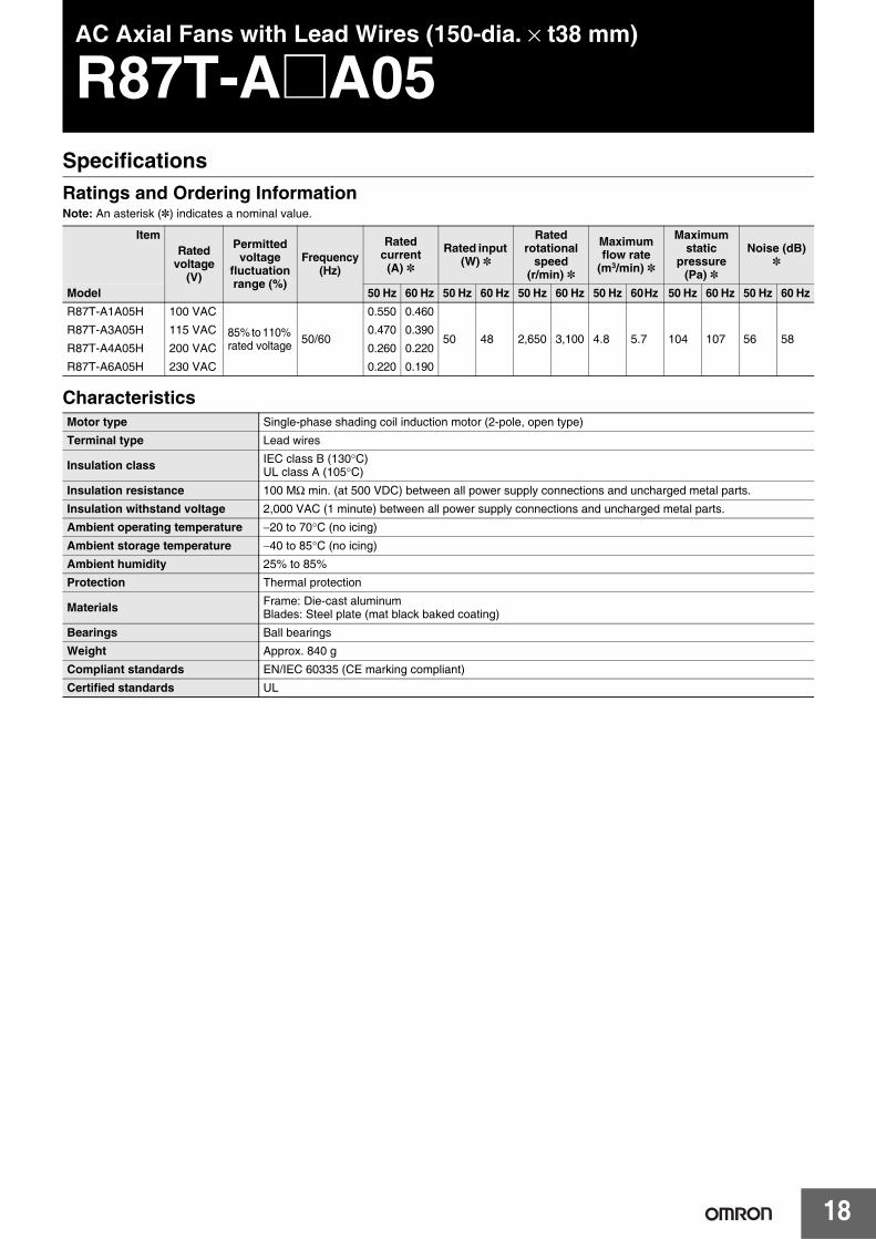
AC Axial Fans with Lead Wires (150-dia. × t38 mm)
R87T-A@A05SpecificationsRatings and Ordering InformationNote: An asterisk (*) indicates a nominal value.
Characteristics
ItemRated
voltage(V)
Permittedvoltage
fluctuationrange (%)
Frequency(Hz)
Rated current (A) *
Rated input (W) *
Rated rotational
speed (r/min) *
Maximum flow rate
(m3/min) *
Maximum static
pressure (Pa) *
Noise (dB) *
Model 50 Hz 60 Hz 50 Hz 60 Hz 50 Hz 60 Hz 50 Hz 60 Hz 50 Hz 60 Hz 50 Hz 60 HzR87T-A1A05H 100 VAC
85% to 110% rated voltage 50/60
0.550 0.460
50 48 2,650 3,100 4.8 5.7 104 107 56 58R87T-A3A05H 115 VAC 0.470 0.390
R87T-A4A05H 200 VAC 0.260 0.220
R87T-A6A05H 230 VAC 0.220 0.190
Motor type Single-phase shading coil induction motor (2-pole, open type)
Terminal type Lead wires
Insulation class IEC class B (130°C)UL class A (105°C)
Insulation resistance 100 MΩ min. (at 500 VDC) between all power supply connections and uncharged metal parts.
Insulation withstand voltage 2,000 VAC (1 minute) between all power supply connections and uncharged metal parts.
Ambient operating temperature −20 to 70°C (no icing)
Ambient storage temperature −40 to 85°C (no icing)
Ambient humidity 25% to 85%
Protection Thermal protection
Materials Frame: Die-cast aluminum Blades: Steel plate (mat black baked coating)
Bearings Ball bearings
Weight Approx. 840 g
Compliant standards EN/IEC 60335 (CE marking compliant)
Certified standards UL

19
R87F/R87T
Flow Rate and Static Pressure Characteristics (Reference Value)
Note: For details on measurement conditions, refer to Flow Rate and Static Pressure on Safety Precautions for All Axial Fans.
Dimensions (Unit: mm)
Panel Cutouts
Options
R87T-A@A05H
Name Model Datasheet availableFinger Guard R87F-FG150 Refer to page 25.
Sta
tic p
ress
ure:
Ps
(Pa)
Flow rate: Q (m3 /min)
50 Hz
20
40
60
80
100
120
0 0 1.0 2.0 3.0 4.0 5.0 6.0
60 Hz
7
Ground Screw Section
6±0.3 6±0.3
38±0.5
146 dia. 144 dia.
Direction of flow
175±1.5
Four, 4.3 dia.151 dia.
Direction of rotation
3000.5 sq
162±0.3
162±0.3
146 dia.
Two, 4.5 dia.
Outlet and Inlet
In the interest of product improvement, specifications are subject to change without notice.
ALL DIMENSIONS SHOWN ARE IN MILLIMETERS.To convert millimeters into inches, multiply by 0.03937. To convert grams into ounces, multiply by 0.03527.

20
AC Axial Fans with Lead Wires (150-dia. × t55 mm)
R87T-A@A07SpecificationsRatings and Ordering InformationNote: An asterisk (*) indicates a nominal value.
Characteristics
ItemRated
voltage(V)
Permittedvoltage
fluctuationrange (%)
Frequency(Hz)
Rated current (A) *
Rated input (W) *
Rated rotational
speed (r/min) *
Maximum flow rate
(m3/min) *
Maximum static
pressure (Pa) *
Noise (dB) *
Model 50 Hz 60 Hz 50 Hz 60 Hz 50 Hz 60 Hz 50 Hz 60 Hz 50 Hz 60 Hz 50 Hz 60 HzR87T-A1A07H 100 VAC
85% to 110% rated voltage 50/60
0.480 0.420
43 40 2,800 3,250 5.0 5.8 118 88 52 56R87T-A3A07H 115 VAC 0.420 0.370
R87T-A4A07H 200 VAC 0.240 0.210
R87T-A6A07H 230 VAC 0.210 0.190
Motor type Single-phase shading coil induction motor (2-pole, open type)
Terminal type Lead wires
Insulation class IEC class B (130°C)UL class A (105°C)
Insulation resistance 100 MΩ min. (at 500 VDC) between all power supply connections and uncharged metal parts.
Insulation withstand voltage 2,000 VAC (1 minute) between all power supply connections and uncharged metal parts.
Ambient operating temperature −20 to 70°C (no icing)
Ambient storage temperature −40 to 85°C (no icing)
Ambient humidity 25% to 85%
Protection Thermal protection
Materials Frame: Die-cast aluminum Blades: Steel plate (black coating)
Bearings Ball bearings
Weight Approx. 1,200 g
Compliant standards EN/IEC 60335 (CE marking compliant)
Certified standards UL

21
R87F/R87T
Flow Rate and Static Pressure Characteristics (Reference Value)
Note: For details on measurement conditions, refer to Flow Rate and Static Pressure on Safety Precautions for All Axial Fans.
Dimensions (Unit: mm)
Panel Cutouts
Options
R87T-A@A07H
Name Model Datasheet availableFinger Guard R87F-FG150 Refer to page 25.
50 Hz
60 Hz
20
40
60
80
100
120
140
00 1 2 3 4 5 6 7
Sta
tic p
ress
ure:
Ps
(Pa)
Flow rate: Q (m3/min)
175±1.5
Four, 4.3 dia.
150±0.5 dia.
6±0.3 6±0.3
55±0.5
146 dia. 144 dia.
3000.5 sq
Direction of flow Direction of rotation
162±0.3
7
Ground Screw Section
162±0.3
146 dia.
Two, 4.5 dia.
Outlet and Inlet
In the interest of product improvement, specifications are subject to change without notice.
ALL DIMENSIONS SHOWN ARE IN MILLIMETERS.To convert millimeters into inches, multiply by 0.03937. To convert grams into ounces, multiply by 0.03527.
22
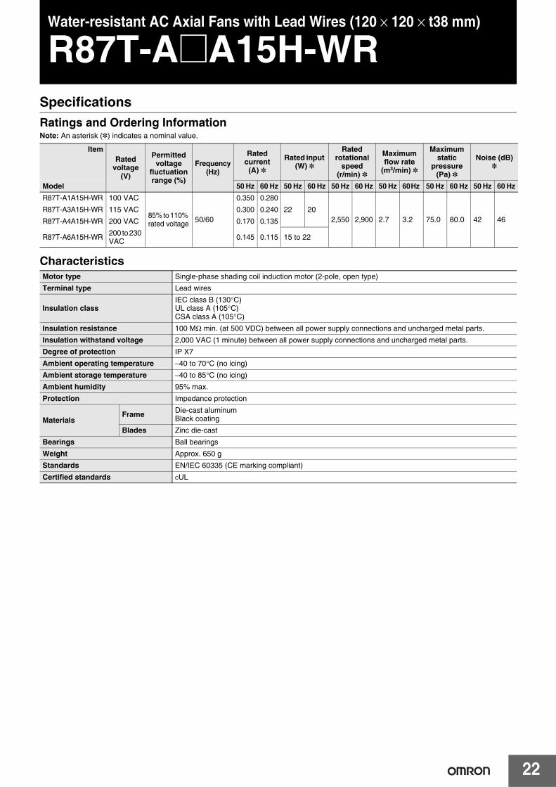
Water-resistant AC Axial Fans with Lead Wires (120 × 120 × t38 mm)
R87T-A@A15H-WRSpecificationsRatings and Ordering InformationNote: An asterisk (*) indicates a nominal value.
Characteristics
ItemRated
voltage(V)
Permittedvoltage
fluctuationrange (%)
Frequency(Hz)
Rated current(A) *
Rated input (W) *
Rated rotational
speed(r/min) *
Maximum flow rate
(m3/min) *
Maximum static
pressure (Pa) *
Noise (dB) *
Model 50 Hz 60 Hz 50 Hz 60 Hz 50 Hz 60 Hz 50 Hz 60 Hz 50 Hz 60 Hz 50 Hz 60 HzR87T-A1A15H-WR 100 VAC
85% to 110% rated voltage 50/60
0.350 0.280
22 202,550 2,900 2.7 3.2 75.0 80.0 42 46
R87T-A3A15H-WR 115 VAC 0.300 0.240
R87T-A4A15H-WR 200 VAC 0.170 0.135
R87T-A6A15H-WR 200 to 230 VAC 0.145 0.115 15 to 22
Motor type Single-phase shading coil induction motor (2-pole, open type)
Terminal type Lead wires
Insulation classIEC class B (130°C)UL class A (105°C)CSA class A (105°C)
Insulation resistance 100 MΩ min. (at 500 VDC) between all power supply connections and uncharged metal parts.
Insulation withstand voltage 2,000 VAC (1 minute) between all power supply connections and uncharged metal parts.
Degree of protection IP X7
Ambient operating temperature −40 to 70°C (no icing)
Ambient storage temperature −40 to 85°C (no icing)
Ambient humidity 95% max.
Protection Impedance protection
Materials Frame Die-cast aluminum
Black coating
Blades Zinc die-cast
Bearings Ball bearings
Weight Approx. 650 g
Standards EN/IEC 60335 (CE marking compliant)
Certified standards CUL

23
R87F/R87T
Flow Rate and Static Pressure Characteristics (Reference Values)
Note: For details on measurement conditions, refer to Flow Rate and Static Pressure on Safety Precautions for All Axial Fans.
Dimensions (Unit: mm)
Panel Cutouts
OptionsName Model Page number
Finger Guard R87F-FG120 Refer to page 25.
Filter R87F-FL120(S) Refer to page 26.
50 Hz
60 Hz
80
60
40
20
0 0 1.0 2.0 3.0
Sta
tic p
ress
ure
Ps
(Pa)
Flow rate Q (m3/min)
R87T-A@A15H-WR
Direction of flow Direction of rotationEight, 4.3 dia.M4 × 0.7
double sems screw
1,000UL1333 AWG22
Lead wire groove(coated with sealant)
119.5±0.5
104.8±0.3
4±0.34±0.3
38±0.5
119.5±0.5
104.8±0.3
11
M4 screw: 0.7 pitch
Ground Screw Section
104.8±0.3
104.8±0.3
115
104.8±0.3
115 104.8±0.3
126 dia. 115 dia.
Four, 4.5 dia. Four, 4.5 dia.
Outlet Inlet
In the interest of product improvement, specifications are subject to change without notice.
ALL DIMENSIONS SHOWN ARE IN MILLIMETERS.To convert millimeters into inches, multiply by 0.03937. To convert grams into ounces, multiply by 0.03527.

24
Plug Cord
R87F-PCAccessories (Order Separately)Available Models
Dimensions (Unit: mm)
Note: This Plug Cord is used for Axial Fans with terminals.
Cord length Model number Weight (g)1 m R87F-PC 39
2 m R87F-PC-20 69
R87F-PC Rating: 250 VAC, 3 AUL-certified Plug Cord
15.5±0.5
9±0.5 7.5±0.5
18±0.5
(8)
1,00023.5±0.5
R87F-PC
Connectable to Faston #110 terminals (or equivalent).
In the interest of product improvement, specifications are subject to change without notice.
ALL DIMENSIONS SHOWN ARE IN MILLIMETERS.To convert millimeters into inches, multiply by 0.03937. To convert grams into ounces, multiply by 0.03527.
25
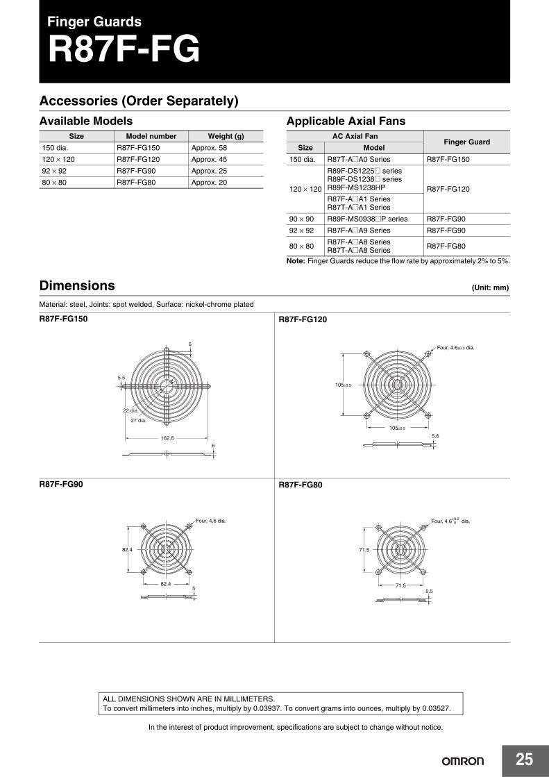
Finger Guards
R87F-FGAccessories (Order Separately)Available Models Applicable Axial Fans
Note: Finger Guards reduce the flow rate by approximately 2% to 5%.
Dimensions (Unit: mm)
Material: steel, Joints: spot welded, Surface: nickel-chrome plated
Size Model number Weight (g)150 dia. R87F-FG150 Approx. 58
120 × 120 R87F-FG120 Approx. 45
92 × 92 R87F-FG90 Approx. 25
80 × 80 R87F-FG80 Approx. 20
AC Axial FanFinger Guard
Size Model150 dia. R87T-A@A0 Series R87F-FG150
120 × 120
R89F-DS1225@ seriesR89F-DS1238@ seriesR89F-MS1238HP R87F-FG120R87F-A@A1 SeriesR87T-A@A1 Series
90 × 90 R89F-MS0938@P series R87F-FG90
92 × 92 R87F-A@A9 Series R87F-FG90
80 × 80 R87F-A@A8 SeriesR87T-A@A8 Series R87F-FG80
162.6
22 dia.
27 dia.
6
5.5
6
R87F-FG150
5.6
105±0.5
105±0.5
Four, 4.6±0.3 dia.
R87F-FG120
Four, 4.6 dia.
5
82.4
82.4
R87F-FG90
71.5
71.55.5
Four, 4.6+0.2 0 dia.
R87F-FG80
In the interest of product improvement, specifications are subject to change without notice.
ALL DIMENSIONS SHOWN ARE IN MILLIMETERS.To convert millimeters into inches, multiply by 0.03937. To convert grams into ounces, multiply by 0.03527.

26
Filters
R87F-FLAccessories (Order Separately)Available ModelsFilter
Note: The filter contains one medium.
Media
Note: Use the following model number to order the Media only.R87F-FL@-M@ (@: 120, 90, or 80) (One set containing five Media, weight: 5 g max.)
Applicable Axial Fans
Note: Filters reduce the flow rate by approximately 20% to 40%. Ensure that there is no clogging.
Size Model number Weight (g)120 × 120 R87F-FL120 Approx. 4392 × 92 R87F-FL90 Approx. 3080 × 80 R87F-FL80 Approx. 21120 × 120 R87F-FL120S Approx. 19
Size Model number120 × 120 R87F-FL120-M12092 × 92 R87F-FL90-M9080 × 80 R87F-FL80-M80
AC Axial Fan FilterSize Model Plastic Aluminum
150 dia. R87T-A@A0 Series --- ---
120 × 120
R89F-DS1225@ series
R87F-FL120 R87F-FL120SR89F-DS1238@ seriesR89F-MS1238HPR87F-A@A1 SeriesR87T-A@A1 Series
92 × 92 R87F-A@A9 Series R87F-FL90 ---
80 × 80 R87F-A@A8 SeriesR87T-A@A8 Series R87F-FL80 ---
Plastic filter
Guard
Media
Retainer
R87F-FL@Plastic Filter
Mounting Method1. Attach the guard to the Fan using the
mounting bolts. (There are no mounting bolts provided with the Plastic Filter.)
2. With the media held between the retainer and the guard, hook the retainer to the guard. (The Media and retainer can be one-touch mounted/dismounted.)
Screen filter
R87F-FL120SScreen Filter
Dimensions (Unit: mm)
123.7
123.7
10.5
Four, 4.5-dia.
104.8118
6.3
104.8118
R87F-FL120
96.5
96.5 82.5
93.5
Four, 3.8 dia.
10.5
82.593.5
R87F-FL90
83.5
83.5 71.380
Four, 4.5-dia.
5.810
71.380
R87F-FL80
2 4
Aluminum frame
Stainless steel screen
Four, 4.3 dia.
119.5±0.5
119.5±0.5
104.8±0.3
104.8±0.3
R87F-FL120SNote: 1. The Screen Filter is
made using aluminium and has an EMI/RFI shielding effect.
2. When mounting the Screen Filter, make sure that it does not come in contact with the fan blades.
3. The screen is a 30 × 30 aluminum mesh.(30 aluminum wires per inch)
27
R87F/R87T
In the interest of product improvement, specifications are subject to change without notice.
ALL DIMENSIONS SHOWN ARE IN MILLIMETERS.To convert millimeters into inches, multiply by 0.03937. To convert grams into ounces, multiply by 0.03527.

Terms and Conditions Agreement Read and understand this catalog. Please read and understand this catalog before purchasing the products. Please consult your OMRON representative if you have any questions or comments. Warranties. (a) Exclusive Warranty. Omron’s exclusive warranty is that the Products will be free from defects in materials and workmanship for a period of twelve months from the date of sale by Omron (or such other period expressed in writing by Omron). Omron disclaims all other warranties, express or implied. (b) Limitations. OMRON MAKES NO WARRANTY OR REPRESENTATION, EXPRESS OR IMPLIED, ABOUT NON-INFRINGEMENT, MERCHANTABILITY OR FITNESS FOR A PARTICULAR PURPOSE OF THE PRODUCTS. BUYER ACKNOWLEDGES THAT IT ALONE HAS DETERMINED THAT THE PRODUCTS WILL SUITABLY MEET THE REQUIREMENTS OF THEIR INTENDED USE. Omron further disclaims all warranties and responsibility of any type for claims or expenses based on infringement by the Products or otherwise of any intellectual property right. (c) Buyer Remedy. Omron’s sole obligation hereunder shall be, at Omron’s election, to (i) replace (in the form originally shipped with Buyer responsible for labor charges for removal or replacement thereof) the non-complying Product, (ii) repair the non-complying Product, or (iii) repay or credit Buyer an amount equal to the purchase price of the non-complying Product; provided that in no event shall Omron be responsible for warranty, repair, indemnity or any other claims or expenses regarding the Products unless Omron’s analysis confirms that the Products were properly handled, stored, installed and maintained and not subject to contamination, abuse, misuse or inappropriate modification. Return of any Products by Buyer must be approved in writing by Omron before shipment. Omron Companies shall not be liable for the suitability or unsuitability or the results from the use of Products in combination with any electrical or electronic components, circuits, system assemblies or any other materials or substances or environments. Any advice, recommendations or information given orally or in writing, are not to be construed as an amendment or addition to the above warranty. See http://www.omron.com/global/ or contact your Omron representative for published information. Limitation on Liability; Etc. OMRON COMPANIES SHALL NOT BE LIABLE FOR SPECIAL, INDIRECT, INCIDENTAL, OR CONSEQUENTIAL DAMAGES, LOSS OF PROFITS OR PRODUCTION OR COMMERCIAL LOSS IN ANY WAY CONNECTED WITH THE PRODUCTS, WHETHER SUCH CLAIM IS BASED IN CONTRACT, WARRANTY, NEGLIGENCE OR STRICT LIABILITY. Further, in no event shall liability of Omron Companies exceed the individual price of the Product on which liability is asserted. Suitability of Use. Omron Companies shall not be responsible for conformity with any standards, codes or regulations which apply to the combination of the Product in the Buyer’s application or use of the Product. At Buyer’s request, Omron will provide applicable third party certification documents identifying ratings and limitations of use which apply to the Product. This information by itself is not sufficient for a complete determination of the suitability of the Product in combination with the end product, machine, system, or other application or use. Buyer shall be solely responsible for determining appropriateness of the particular Product with respect to Buyer’s application, product or system. Buyer shall take application responsibility in all cases. NEVER USE THE PRODUCT FOR AN APPLICATION INVOLVING SERIOUS RISK TO LIFE OR PROPERTY OR IN LARGE QUANTITIES WITHOUT ENSURING THAT THE SYSTEM AS A WHOLE HAS BEEN DESIGNED TO ADDRESS THE RISKS, AND THAT THE OMRON PRODUCT(S) IS PROPERLY RATED AND INSTALLED FOR THE INTENDED USE WITHIN THE OVERALL EQUIPMENT OR SYSTEM. Programmable Products. Omron Companies shall not be responsible for the user’s programming of a programmable Product, or any consequence thereof. Performance Data. Data presented in Omron Company websites, catalogs and other materials is provided as a guide for the user in determining suitability and does not constitute a warranty. It may represent the result of Omron’s test conditions, and the user must correlate it to actual application requirements. Actual performance is subject to the Omron’s Warranty and Limitations of Liability. Change in Specifications. Product specifications and accessories may be changed at any time based on improvements and other reasons. It is our practice to change part numbers when published ratings or features are changed, or when significant construction changes are made. However, some specifications of the Product may be changed without any notice. When in doubt, special part numbers may be assigned to fix or establish key specifications for your application. Please consult with your Omron’s representative at any time to confirm actual specifications of purchased Product. Errors and Omissions. Information presented by Omron Companies has been checked and is believed to be accurate; however, no responsibility is assumed for clerical, typographical or proofreading errors or omissions.
2019.8
In the interest of product improvement, specifications are subject to change without notice.
OMRON Corporation Industrial Automation Company http://www.ia.omron.com/
(c)Copyright OMRON Corporation 2019 All Right Reserved.