linear translation stage · how to make a motorized linear translation stage ... by converting...
TRANSCRIPT

1
How to make a Motorized Linear Translation Stage
MalaMateenCollegeofOpticalSciences,UniversityofArizona.
November26,2009
Abstract
Motionstagesallowcontrolled,precise,andrepeatablemotioninasingledegreeoffreedom.Avarietyofdifferentstagesareavailableonthemarketwhichallowlineartranslation, rotation, tilt, and even multi‐axis motion. In this tutorial we willconcentrate on building a motorized linear translation stage. Purchasing ready‐made motorized linear stages can be very expensive, for instance a lineartranslationstageallowing12mmoftravelinonedirectionwithasteppermotorcancostbetween$1500to$2000fromThorlabs[1].Belowweoutlineacosteffectivewaytobuildamotorizedlineartranslationstage.
Introduction
Alinearstageisusedtoallowmotionalongonedegreeoffreedomandtoconstrainallotherdegreesofmotion.Linearstagescanallowrotationabout roll,pitch,andyawanglesortranslationalongx,y,andzaxis[2].Alinearmotionstageconsistsofthefollowingparts:1).Linearstageorcarriage2).Rails3).Stepperdriver4).Steppermotorwithlinearactuator5).Opto‐interrupter6).LabpowersupplyTheresolutionof thestage isquantifiedbythestepsizeof thesteppermotorandtherepeatabilityisdrivenbyhowmuchfrictionispresentbetweentherailbearingsandthecarriage.Repeatabilityandresolutionarealsodrivenbyhowaccuratelythemotor responds to commands. It is important that the stage and rails are able towithstand thewait of the instrument that youwant tomove,with out deformingotherwise the performance of the ball bearings and the length of the translationstagewillbeaffected.Properlockingmechanismforthestageneedstobeinplacetogive the linear stagestability.Toavoiddriving the linearactuatorclearoutof thesteppermotorortoavoiddrivingtheinstrumentoffthestagepropercalibrationofstep size to linear translation needs to be performed at the beginning to theexperiment.

2
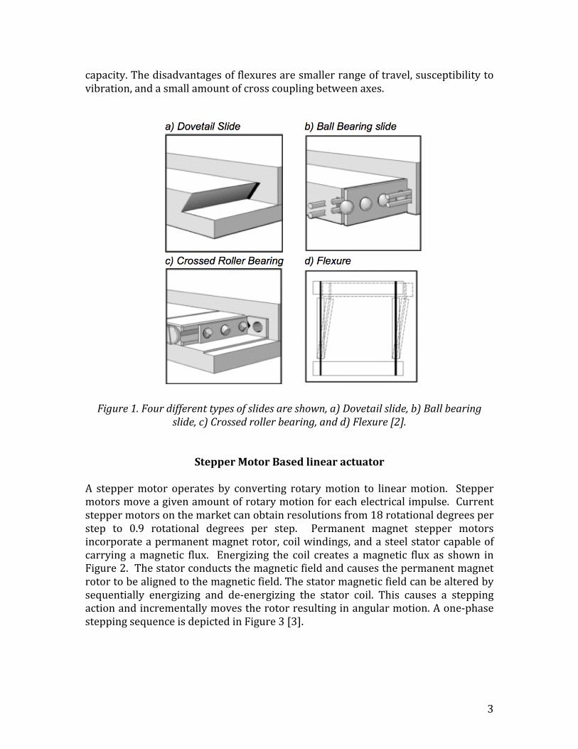
LinearSageandSlideThe linear stage is what the instrument (camera, membrane, or mirror) that wewant tomove,sitsone. Itconsistsofoneormoreslidessandwichedbetweentwometal plates. The instrument is boltedon to the topplate,which is free tomovewith theslides.Thebottomplate is locked to theopticalbench.The leadactuatorboresintothetopmetalplateproducingthetranslation.Theslidesplustheflatmetalplatesshouldbeabletowithstandtheweightoftheinstrument without deforming. Therefore a material with high specific stiffnessshouldbeused.Themetal plates shouldbewide enough to comfortably span thebreadth of he instrument. For large instruments two slides can be used to lendstability.Thetworailscanthenbeappropriatelypositionedonthemetalplatestoallowsmoothtranslation.Theperformanceofatranslationstageisdeterminedbythetypeofbearingsused.Thereareavarietyofdifferenttypesofrailsorslides,fourmajortypesofslidesaredovetail slides,ballbearing slides, crossed rollerbearings, and flexure suspension[2].Dovetail slides are the simplest type linear translation slides. They consist of twoflat surfaces sliding against each other with the geometry shown in figure 1(a).Dovetailslideshaverelativelyhighstiffnessandloadcapacity.Theyareresistanttoshockandfairlyimmunetocontamination.Thefrictionofdovetailslidesvarieswithtranslationspeed,whichmakesprecisecontroldifficultandlimitstheresolutionofthestage.Ballbearingslidesreduce frictionbyreplacingslidingmotionwithrollingmotion.Inthisarrangementtheballsareallowedtoslidebackandforthagainststeelrodsknownas guidesways (Figure1 (b)). The frictionbetween theball bearings andguidewaysisverylowresultinginsmoothtravelwiththecapabilitytomakesmallcontrolledmovements. The ball bearingsmake contactwith the guideways at asingle location allowing thedirt tobepushedout insteadof getting trapped.Thismakestheballbearingslidesrelativelyinsensitivetocontamination.Crossed roller bearings replace the point contact of ball bearings with the linecontactofa roller.This leads tohigher loadcapacityandhigherstiffness.Crossedrollerbearingsrequiremorecareduringassemblyresultinginhighercostsandarethus reserved for applications that require the greatest stability, stiffness, androbustness.Flexuresuseelasticdeformationtocontrolmotion(Figure1(d)).Sincethereisnosliding or rolling contact between the moving parts of the stage, friction iscompletelyeliminated. Flexuresuspensionallowshigherstiffnessandhigher load
3
capacity.Thedisadvantagesofflexuresaresmallerrangeoftravel,susceptibilitytovibration,andasmallamountofcrosscouplingbetweenaxes.
Figure1.Fourdifferenttypesofslidesareshown,a)Dovetailslide,b)Ballbearingslide,c)Crossedrollerbearing,andd)Flexure[2].
StepperMotorBasedlinearactuator
A steppermotor operates by converting rotarymotion to linearmotion. Steppermotorsmoveagivenamountofrotarymotionforeachelectricalimpulse.Currentsteppermotorsonthemarketcanobtainresolutionsfrom18rotationaldegreesperstep to 0.9 rotational degrees per step. Permanent magnet stepper motorsincorporateapermanentmagnetrotor,coilwindings,andasteelstatorcapableofcarrying amagnetic flux. Energizing the coil creates amagnetic flux as shown inFigure2.Thestatorconductsthemagneticfieldandcausesthepermanentmagnetrotortobealignedtothemagneticfield.Thestatormagneticfieldcanbealteredbysequentially energizing and de‐energizing the stator coil. This causes a steppingactionandincrementallymovestherotorresultinginangularmotion.Aone‐phasesteppingsequenceisdepictedinFigure3[3].

4
Figure2.Anorthtosouthmagnetfieldiscreatedandmagneticfluxisgeneratedinthecoil[3].
Figure3.Illustratesthestepsequencefora2phasemotor.Instep1phaseAofthe2stepstatorisenergized.Thismagneticallylockstherotorinthepositionshownsinceoppositemagneticpolesattract.WhenphaseAisturnedoffandphaseBisturnedontherotormoves90°clockwise.Instep3phaseBisturnedoffandphaseAisturnedonwith the polarity reversed from step 1. This causes another 90° rotation. In step 4phaseAisturnedoffandphaseBisturnedonwiththepolarityreversedfromstep2.Repeatingthissequencecausestherotortorotatein90°increments[3].Alinearactuatorproducesalineartranslation.Insidetherotorthereisathreadedprecisionnutwitha lead screw.The lead screw in turn is fixed to the translationstagewithanut.As therotor turns linearmotion isachieveddirectly throughthe

5
nut and threaded screw. The size of the leadscrew depends on the range oftranslation required. The precision of themotion depends on the step size of thesteppermotorandonthecouplingbetweenthemotorandleadscrew.Thethreadsof the lead screw allow a small rotational force to translate into a large loadcapabilitydependingonthesteepnessoftheramp,whichisafunctionofthelead,pitch,anddiameterofthescrew.Asmalllead(morethreadsperinch)willprovideahighforceandresolutionoutput.Alargelead(fewerthreads)willprovidealowerforce, but correspondingly higher linear speed. An example of different leadconfigurationsisshowninFigure4[4].
Figure4.Fourdifferentleadscrewsshowingfourdifferentleads[4].
Inchoosingarotorplusleadscrewyouneedtoconsiderhowmuchtorque/forceisrequired? What is the duty cycle, desired step increment, step rate, and maxtranslationrange. Bipolarorunipolarcoilsareselecteddependingonwhetherornot dual directionalmotion is needed)?We also need to consider life expectancyrequirementandenvironmentalconstraints. Astepperdriver isused todrive thesteppermotorandlinearactuator.
ApparatusandAssembly
Inthissectionweconstructamotorizedlinearstageforaspecificapplicationlistingtheparticularparts,wheretopurchasethem,andhowtoassemblethepartstohaveanoperationalmotorizedlineartranslationstage. WelistallthepartsneededandwheretheycanbepurchasedinTable1.

6
Part PartNumber
Quantity PartDescription
Vendor Cost
Aluminumblock
N/A 1 20x100x200mmplatestoformthebaseandtopofthetranslationstage.90°CornerPlate(100mminlength)tomountadditionalcomponents
Aluminumblockfoundinlabandcutinthemachineshop.CanalsobepurchasedfromMcMaster‐Carr.
$0
Telescopicballbearingslides
8379K1 2 76mmstrokelength.
McMaster‐Carr
$90.89/each
Steppermotor+leadscrew
28F49‐05‐023ENG
1 Non‐captive,series28000,size11with4inleadscrew.
HaydonKerk $120.88
StepperdriverKit
EZHR17ENSK 1 1EZHR17ENsteppermotorcontroller+driver.1RS485converter.1opto‐interrupter.
AllMotion $225
Hexnut 932827A225 1 Usedtobolttheleadscrewtothetranslationstage
McMaster‐Carr
$11.55/packof100.
Socketcapscrew
92196A533 4 ¼‐20.Usedtoboltaluminumpoststothealuminumbaseplate.
McMaster‐Carr
$3.53 / packof25.
Socketcapscrew
92196A619 4 3/8‐16.Usedtobolttheslidestothealuminumbaseplate.
McMaster‐Carr
$6.95 /packof10.
Setscrews 91375A33 6 ¼‐20cup. McMaster‐Carr
$11 / pack of$100.
Posts NT59‐754 6 3inpostswith¼‐20studatthetopand¼‐20tappedthreadedholeatbottom.
EdmundOptics.
$9.75/post
PowerSupply InstekPST‐3201
1 Labpowersupply Tequipment $873
Table1.Listoftheapparatusneededtobuildanddrivealineartranslationstage.
TheapplicationistomoveandAndoriXoncamerathroughadistanceofabout60to70mm in 1.5mm increments. The cameraweights 4.5 kg (~10 lbs). There is nohard‐set constraint on the speed with which to move the camera. From theserequirementswecandeterminethesizeoftheleadscrew,thepowerofthesteppermotor,andthestepsizeorresolutionneeded.Thefollowingformulacanbeusedtodeterminethepowerofthemotor[3]:

7
Powerlinear(watts)=[distancetravelled(m)*force(N)]/[timetaken(sec)]
SeveraloptionsofmotorsbasedonframesizesandpowerareavailablefromthevendorHaydonKerk.Figure5showsplotofforcevs.speedprovidedbythevendor.Thisplotisveryhelpfulinchoosingthecorrectmotorforyourapplication.
Figure5.Powercurvesshowingtheperformanceofthe28000seriessize11steppermotors[3].Basedontheaboveplotifwewanttomoveacamera,whichweighsabout10lbsataspeedof0.4in./sec.wewilloptformotor9.Thismotorprovidesaresolutionof0.0025 in./step (0.0063mm/step). Forourapplicationwe select the28000series,Non‐captive,size11steppermotorwitha4inchleadscrew.ThecharacteristicsforthismotorareprovidedintheTable2[5].

8
Table2.SalientcharacteristicsforaSeries28000,size11motor[5].
To power the steppermotorwe used the EZHR17ENSK starter kit, which can bepurchased from All Motion [6]. The kit includes an EZHR17EN (2 Amp, 40 V)stepper motor controller plus driver, and RS485 converter and cables. Wepurchased the Instek PST‐3201 power supply from Tequipment. This is a fairlyfancyandhenceexpensivepowersupply.Acheapermorebasicpowersupplycaneasilybesubstituted.FollowtheinstructionsbelowandlookatthehookupdiagramshowninFigure6topowerthesteppermotor:1. StartwithpowersupplyOFF.ConnectpowersupplytoRS485converter.2. Turnpoweron,confirmcurrentis.Turnpoweroff.3. ConnectEZsteppertoRS485Converter.4. Connectsteppermotortomiddlefourpinsofthemotorconnectorasshownin
thediagrambelow.Motorshouldexecuteafactorystoredcommand.5. Ifaddressswitchisnotalreadyat1,setitto1withPhillipsscrewdriver.6. TurnpowerON.7. ConnectRS485convertertocomputer.8. Launch a terminal window on your Linux machine and type the following
command. > echo “/1A100000R” > /dev/ttySO. This will move the steppermotor toanabsoluteposition100000.Similarly thereareothercommands intheEZsteppermanualthatshowyouhowtozerothelocationetc.

9
9. Sendcommandstodrivetheleadscrewtoitsmaximumlengthsothatonlyonethread is visible from the back end of the motor. Measure the length of theleadscrewemergingfromthesteppermotor.Notehowmanystepsittooktogettothispositionandusethisinformationtocalibratethesteppermotor.
Figure6.SchematicshowinghowtoconnecttheEZSteppertotheRS485converter,thepowersupplyandthecomputer.
Figure7.diagramillustratinghowtoconnectsteppermotortomotorconnector[6].

10
WeoptforballbearingrailsthatcanbepurchasedfromMcMaster‐Carr(Figure8)[7].
Figure8.TelescopicBallbearings[7].
Wechoosea20x100x200mmAluminumplatetoserveasthebaseofthelineartranslationstage.TherailsaremountedontheAluminumplate(Figure9)andthelinearstageislockedtotheopticalbenchusing3inchpostswith¼‐20tappedholesatthebottomand¼‐20studsatthetop(seeFigure10).
Figure9.Ballbearingslidesscrewedontothebaseofthetranslationstage.Youcanalsoseethesteppermotorboltedtothe90°cornerplate.Thelinearactuatororleadscrewcanbeseenemergingfromtheholecutoutintheplate.

11
Figure10.Translationstagelockedtotheopticsbenchwithfour3inposts.The stepper motor along with the lead screw, the RS485 converter, and the EZStepperaremountedontoa90° cornerplatemadeofAluminum(Figure11).Thecornerplateisboltedtothetranslationstageandmoveswithit.Thesteppermotorisboltedontothecornerplateinwhichaholeiscutoutfromwhichtheleadscrewemergesanddrivesthetranslationstage(Figure9).TheEZstepperandtheRS485converter are held onto the platewith tape. The camera ismounted onto the topplate of the translation stage by screwing two 3 inch posts onto the ball bearingslides that are in turn screwed to the base of the translation stage. The finalassemblyforthemotorizedlineartranslationstageisshowninFigure12.

12
Figure11.FromrighttoleftRS485Converter,steppermotorwithleadscrew,andEZSteppermountedontothe90°cornerplate.
Figure12.Fullyassembledmotorized linear translationstagewiththecameramounted. Thebaseofthetranslationstagesitson4postsandislockedtotheopticsbench.The90°cornerplateismountedtothebaseofthetranslationstageandisthusalsolockedtotheopticsbench.Thetopofthetranslationstageisscrewedtotwoballbearingslidesandtranslatesasthelinearactuatorisdrivenbythesteppermotor. The camera is bolted to the top plate of the translation stage with two posts. The cameratranslateswiththetopplate.

13
ConclusionIn this tutorial we have shown a cost effective way to build a motorized lineartranslation stage. A readymade translation stagewithout the power supply costsbetween $1500 to $2000 from a vendor such as Thorlabs.Whereas constructingyourownmotorizedtranslationstagewillcostyouonly$500to$600dependingonwhetheryoucansalvagemetalplates,screwsandnutsfromthelabandhavethemmachinedtoneedfromthemachineshoporwhetheryouneedtopurchasethem.The tutorial explains how to select slides based on the precision requirements ofyour experiment. It also walks you through how a stepper motor produces arotationandhowthatrotationtranslatestolinearmotion.ThetutorialguidesyouinselectingtherightpowerandresolutionforthesteppermotorandshowsyouhowtopowerandcontrolthesteppermotorusingtheEZStepperstarterkit.References[1]RetrivedfromThorLabsSaleswebsite:http://www.thorlabs.com/NewGroupPage9.cfm?ObjectGroup_ID=2163[2]Burge,J.PrecisionMotion:Useofstages[PDFdocument].RetrievedfromLectureNotesOnline Web site:http://www.optics.arizona.edu/optomech/Fall09/Notes/19%20stages.pdf[3] Stepper Motor Technical Overview: Tutorial. Retrieved from Haydon Kerk ResourcesOnlineWebsite:http://www.haydonkerk.com/LinkClick.aspx?fileticket=ejPD9ZRlN%2bw%3d&tabid=221[4] Overview of Leadscrew Assemblies: Retrieved from Haydon Kerk Resources andDownloads Online Web site:http://www.haydonkerk.com/LinkClick.aspx?fileticket=jr80YbT3t4M=&tabid=258[5]RetrievedfromHaydonKerksSalesOnlineWebsite:http://www.haydonkerk.com/Products/StepperMotorLinearActuators/HybridLinearActuators/28000Series/tabid/75/Default.aspx#chart[6]EZStepperStarterKit:Tutorial[Apdfdocument].RetrievedfromAllMotionOnlineWebsite:http://www.allmotion.com/PDF_Datasheets/EZ_Start.pdf[7] Drawing for Telescopic Ball Bearing Slide retrieved fromMcMaster‐Carr Sales OnlineWebsite:http://www.mcmaster.com/#linear‐motion‐slides/=4o9o1e