linear systems design guide - peerlesslighting2 linear systems design guide • 2015. ... a...
TRANSCRIPT

LINEAR SYSTEMS DESIGN GUIDEP E E R L E S S L E D L U M I N A R I E S I N T E G R A T E D W I T H C O N T R O L S

Steps to Create a Complete Lighting & Controls Design ...........................4
Fixture connections and wiring by type .....................................................8 Overview - Determine your specified fixture type
Integral driver/single circuit diagrams
Integral driver/dual circuit diagrams
Remote driver/single circuit diagrams
Remote driver/dual circuit diagrams
Application Examples ..................................................................................36 Classroom – occupancy sensors only Open office – dual sensors in fixture rows parallel to window Open office – dual sensors in fixture rows perpendicular to window
Appendices ................................................................................................... 39 Appendix 1 - Energy savings and system life benefits of dimming
• Lumen management• Manual dimming and overrides• Occupancy sensing savings• Daylight sensing savings• Multiplier effect
Appendix 2 - Daylighting standards and codes
Appendix 3 – Acuity Brands devices and product capabilities• Occupancy sensor• Daylight sensor• Driver• Embedded controller• CAT-5e cables and splitters
Appendix 4 - Basic wiring examples with Peerless luminaires
Appendix 5 - Basic installation components at the ceiling with Peerless luminaires
Appendix 6 – Overview of integration into a larger nLight building system
Contents
Linear Systems Design Guide • 20152

IntroductionSpecifying Peerless® Lighting LED luminaires with Controls from Acuity Brands® gives you a tremendous amount of flexibility and control when lighting a space. There are many different options depending on the desired outcomes. This design guide demonstrates how the different Acuity Brands components work together and how to make the best design decisions by referencing best practice examples – giving you the tools to specify an Acuity Brands linear lighting and controls solution with confidence.
This Guide is designed to demonstrate how Peerless linear suspended fixtures are configured with Acuity Controls nLight® digital lighting system, and help you determine what you need on your projects. With so many variations and options to choose from, a conceptual framework, examples can go a long way to helping you make specification decisions.
Once you choose a specific Peerless luminaire, you can review wiring and connections, nLight component functionality, and reference examples of typical fixture runs.
The Guide is organized so you:• Get an overview of the process of lighting and controls design
• Review your fixture type and options to find the appropriate fixture connection diagram and explanation
• See application examples for cues to laying out fixtures and controls in a space
• Can access technical references and information on products and components in the Appendices
How to Use this Guide
Linear Systems Design Guide • 2015 3

STEP
S TO
CR
EATE
A C
OM
PLE
TE L
IGH
TIN
G A
ND
CO
NTR
OLS
DES
IGN Steps to a Complete Linear Lighting and Controls Design
1. Describe what needs to happen in the space
2. Lay out the fixtures
3. Determine whether you need lumen management
4. Check code compliance requirements
5. Determine sensor needs and locations
6. Lay out sensors and nLight devices
Design CheckList
1. Describe the intent with a narrative description of what you want to happenA controls design begins with a description of how you want the system to operate, called the Sequence of Operations. A verbal narrative defines the issues and clarifies the benefits. It provides the basis for determining the components and connections that will be needed (see Applications section for examples).
2. Lay out the fixtures to achieve your lighting goalsThe fixture layout responds to the design intentions, and relates to the overall space, the windows and the tasks. The fixture type, quantity, mounting height above the floor, and row spacing all determine the illuminance levels at the workplane and on other surfaces, as well as the gradient of brightnesses in the space.
3. Determine whether your design includes a driver with lumen maintenanceLumen maintenance programs the driver to maintain a dim level of 80% over the life of the lighting system. It prevents over lighting and overuse of energy at initial installation. (See “Lumen Management” in Appendix #1 for discussion on savings with Lumen Maintenance.)
4. Comply with required codesVarious energy codes and guidelines are in effect to reduce energy consumption of lighting in buildings. Daylight harvesting allows for daylight entering a space to trigger dimming of electric lights and reduce energy consumption. Occupancy sensors dim or switch lights off when the space is vacant. Be sure to check your local requirements.
5. Layout occupancy sensors for good coverageOccupancy sensors pick up signals within a proscribed range. Coverage patterns determine where sensors should be located so that all spaces that need to be monitored for occupancy can be sensed. Aim for sensor locations at the end of fixtures or fixture runs. Overlapping coverage is OK, but minimize overlap for efficiency.
6. Layout daylight sensors to control zonesDaylight sensors respond to light falling on an area on the surface beneath the sensor primarily by sensing the reflected light off that surface (and sensing some of the other light in the space.) It senses the total light on that surface, which may include both daylight and light from fixtures. The location of the sensor should include daylight and a full “view” of the incoming light, without interior or exterior obstructions, for best accuracy. This usually means locating the sensor in a fixture near the center of a set of windows or near a skylight or clerestory window.
You may want an additional daylight zone(s) relative to the window wall where daylight enters to comply with codes or to create a more refined design. This secondary zone can have its own daylight sensor to control fixtures in that zone. Alternatively, a single input from the daylight sensor in the primary zone can dim both zones through commissioning the primary zone to one level; and a secondary zone further from the daylight to another (usually brighter) level. (See Figure 1.) Commissioning involves programming the nLight device that dims fixtures in the secondary zone to a pre-determined offset of the first zone, such as 20% brighter. This allows for multiple daylight zones.
Linear Systems Design Guide • 20154

STEPS TO
CREATE A
COM
PLETE LIG
HTIN
G A
ND
CON
TRO
LS DESIG
N
Daylight Zones Electric Lighting Zone
primary daylight zone secondary daylight zone electric lighting zone0’ 10’ 20’ 30’
Figure 1
This example shows two control zones that have been created where there is ample daylight contribution, and one zone using a standard sensor where daylight is minimal. As daylight contribution increases, sensors automatically and gradually reduce electric light output to save energy.
Determine where the sensors are needed on the luminairesWith nLight enabled fixtures, the sensor controls either a single fixture or run of fixtures, or it controls a networked set of fixtures. When the fixture is specified with a sensor for standalone operation, it controls and dims a single 4-, 8-, or 12ft fixture for example, or a connected run of fixtures up to a maximum allowable number of drivers. The maximum number of drivers an nLight device can control is 15 drivers in most instances. ((15) 4’ single-driver fixtures or (6) 4’ double-driver fixtures.) A networked nLight enabled fixture with a sensor can provide a signal to any number of networked fixtures through the CAT-5e cables. A big advantage of networked fixtures is that they can be addressed individually or as sets over a network.
When using an nLight networked system, individual fixtures within runs of fixtures perpendicular to the window can be addressed and dimmed according to the daylight zone they are in. (see layout #3 in Applications section) Note: With Peerless luminaires, sensors are located at the end of an individual fixture or at the end of a fixture run unless otherwise requested.
Determine where controllers are neededA few simple guidelines determine where controllers are required. First, every fixture with a sensor needs an controller/power pack. When the driver is integral to the fixture, an embedded nLight controller is automatically provided. Every fixture or set of fixtures that is controlled (dimmed) by a networked signal from elsewhere needs an embedded controller, and a CAT-5e cable dropped to the suspended fixture for the communication signal.
When the driver is remote, the nLight controller is located next to the driver enclosure in the ceiling or in a remote location, and there is only a CAT-5e cable drop if there is a sensor.
For a different dimmed response in a zone of fixtures within a single run of fixtures, each zone needs an additional controller and a CAT-5e cable connection. The various zoned responses are programmed when the system is commissioned. In fixtures with integral drivers, the signal to other fixtures in the zone is carried through 0-10V wires that are provided within the fixtures and connect with plug-in electrical connectors at the joints. For remote-driver fixtures, the dimming signal is carried between drivers via 0-10V wires provided by others, starting from the driver enclosure with the nLight device to other drivers in the zone or other drivers in the complete fixture run. (The dimming signal can be communicated via CAT-5e cable to other fixtures in the zone or fixture run if they each have an nLight device, available by special request.)
Linear Systems Design Guide • 2015 5

PEE
RLE
SS F
IXTU
RE
CON
NEC
TIO
NS
Does my fixture have integral drivers or remote drivers? Most Peerless LED fixtures such as Bruno, Staple, Cerra7, Round, and Square have integral drivers, but others such as Vellum and Open have remote drivers with different wiring. Whether remote mounted or mounted within the fixture, the nLight devices and the drivers function the same, but the placement and wiring of the devices depends on their configuration.
Does my fixture have a single or dual set of controls?Switching SCT or DCT – Some Peerless I/D luminaires allow you to control the indirect light separately from the direct light. You have the option of controlling the up and down light together as a single circuit (SCT), or separately as a dual circuit (DCT). Examples of fixtures that have the option of selecting dual circuit control are Square and OPEN.
The subsequent questions address features of the fixture and are options on the spec sheet you will need to specify. They will help you find the appropriate Fixture Connection page for your specific fixture type.
Understanding Fixture and Controls Connections – an Overview
Which driver type? nLight enabled dimming/networked dimming or standard dimming?Each 4’ section in Peerless LED luminaires has one or more EldoLED drivers to power the LED boards in a single-circuit fixture, and will have two or more drivers in a dual-circuit fixture. (see Driver in Appendix 3 - Acuity Brands devices and product capabilities for more details)
Driver Type “ENNB” An nLight enabled fixture has an nLight device that controls the light output. The nLight controller is part of the fixture, mounted either internally (an “embedded controller”) for integral-driver type fixtures OR externally, near the remote driver. The remote location could be either just above a hard ceiling or some distance away. (see maximum distances per wire gauge in fixture installation instructions). The nLight device is typically also a power-pack and can provide power to a local sensor*.
This section includes a set of Fixture Connection diagrams, each with a similar format: a unique conceptual diagram that describes the location and relationships of the power and control feeds, junction boxes, nLight devices, sensors and a suspended 8 ft. linear fixture; a written description of the connections; and a real-life example of a typical submittal drawing layout for a 40’ fixture run. There are a huge number of variations and options for Peerless fixtures, but the most typical are addressed here.
To find the right fixture connection page, you should answer to the following questions, then look up the figure you need.
The Fixture Connection pages are grouped into 4 categories: integral driver-single circuit, integral driver-dual circuit, remote driver-single circuit, and remote driver-dual circuit.
The first 2 questions help you determine in which category your fixture falls.
Peerless square with embedded sensor
Linear Systems Design Guide • 20156

PEER
LESS FIXTUR
E CON
NECTIO
NS
All connections to nLight devices are via a CAT-5e cable, which includes an independent cable drop to the fixtures when the drivers are integral. They are provided as part of the fixture by the factory (see components for specifics). The CAT-5e cable connects devices in any order and is completely expandable. The dimmed responses to each set of fixtures are programmed via software by Acuity Controls through commissioning, either at the fixture or through SensorView®. All fixtures that are networked and “talk” to each other must have an nLight device and an ENNB driver. Fixtures that have Lumen Management can either have an nLight controller or not.
Driver Type “EZB” Fixtures come standard with purple/gray low-voltage control wires and can be controlled with a 0–10V dimming signal from an independent source. This signal can come from a simple 0 – 10V wallbox dimmer, from an external nLight device such as a sensor mounted remotely, or any other device that can connect via 0 - 10V signal wires to the driver.
* Some nLight Emergency controllers are powered from elsewhere in emergency fixtures.
Should I specify a fixture-integrated daylight or occupancy sensor? Whenever there is an integrated sensor, there is an nLight controller either embedded in the fixture (for integral driver types) or in a remote location next to the driver (for remote location types) which provides low voltage “bus” power to the sensor. When the system is networked (Dimming Driver selection is ENNB), the dimming level determined by the sensor can communicate to any fixtures in the networked nLight system, anywhere in the room or even to other rooms.
Without networking it is a standalone system, (Dimming Driver selection is EZB), the dimming level from the sensor controls only that fixture, as well as other fixtures in that the fixture run.
Integrated Sensor Type “DSCC” or “DSCNL” (daylight sensing) - Many Peerless fixtures have sensors that respond to conditions in order to save energy when lights are not needed. The daylight sensor dims in response to daylight so pre-determined light levels are maintained.
Integrated Sensor Type “MSD7DSC” or “MSD7DSNL” (daylight sensing plus occupancy sensing) - The occupancy sensor dims to dark when no one is present, after a pre-set amount of time. The sensors in Peerless fixtures have a factory default of a 10 minute time delay – after 10 minutes of not detecting an occupant, lights dim to dark. The sensor can be specified and programmed with either or both functions. (see Sensors in Appendix 3 - Acuity Brands devices and product capabilities for details.)
Is there an emergency section in the run of fixtures? Is there a nightlight?An emergency circuit or emergency battery pack requires a separate power feed to the emergency section. An individual segment of a fixture run can be designated and wired for additional use as an emergency light, and will come to full light output (100%) when power fails. This is an option for all Peerless luminaires. A light that remains on 24/7 serves as a nightlight.
Linear Systems Design Guide • 2015 7

PEE
RLE
SS F
IXTU
RE
CON
NEC
TIO
NS
The diagrams on the next few pages show the conceptual relationships between types of linear suspended fixtures and controls, including: basic nLight components, sensors, feeds and power supplies. Some show an Emergency Circuit (EC) on a 4’ section of the fixture.
Each Fixture Connection example represents a certain fixture type, identified in a box at the top of the page. It shows a conceptual diagram of a 16’ fixture with (2) 8’ sections, a brief description, typical example of the nomenclature and layout of a real fixture in a 40’ run.
Definitions are noted on the following page.
Peerless fixture connections
Support with power feed
Support only
Power feed, internal
Driver(s) location
embedded nLight device
Line voltage
n
DR
DR encl
Low voltage
0-10V Low Voltage
DC Feed to LEDs
CAT-5e Cable
Emergency Section
Emergency power
Cable support
Sensor
Driver enclosure
0-10V Control Wires
0-10V Control
Figure Legend
Linear Systems Design Guide • 20158

PEER
LESS FIXTUR
E CON
NECTIO
NS
Line Voltage – also called “commercial
power”. Electrical power normally used.
Wires typically hot (black), neutral (white)
and ground (green). In dual-circuit (DCT)
wiring, there is a second hot (red), and
neutral and ground are shared.
Emergency circuit – power provided by a
generator, always available, used when
normal power fails. Wires typically hot,
neutral, ground.
CAT-5e cable – type of CAT5 cable used
to connect nLight system in a daisy chain.
Connections are with snap-in
RJ-45 connectors at ends.
J-box – junction box where wires connect,
usually at ceiling.
Driver enclosure – metal box where drivers
reside. Number of drivers is determined by
the number of circuits and load. The AC and
dimming input connections are behind an
access plate.
0-10V controls – also frequently called
“low voltage” “or low voltage Class 2” or
+/- wires, but here specifically for controlling
dimming signal. They are typically
purple/gray for first circuit. In dual-circuit,
first uses purple/gray wires, and second
uses blue/blue-white wires.
Splitter – small device for connecting
3 RJ-45 cable inputs in daisy chain.
Sensor – device for sensing occupancy/
vacancy and/or daylight so appropriate
control can be initiated, usually dimming to
black or dimming to a predetermined level.
In this Guide, sensors are embedded in the
linear fixtures.
Emergency module – a 4’ run of fixture
wired to provide light at full light output
when the line voltage power fails. In dual-
circuit fixtures, only the downlight portion of
a 4’ module is emergency.
nLight controller device – a dimming or
on/off control device that operates with
our LED drivers. Powered by the driver,
or through CAT-5e cable from other
nLight controllers. May be providing
power to other nLight devices, depending
on type. Dimming control signal can be
communicated to other nLight devices
thorough CAT-5e cable or via 0-10V control
wires to establish dimming level of drivers
in a fixture run or zone.
DC feed to LEDs – also frequently called
“low voltage power”. Carries power from
driver DC (direct current) output to LEDs to
provide light. In remote-driver fixtures, DC
feed to LEDs is within a provided cord.
Support with power feed – location of
power feed or CAT-5e feed on suspended
fixture, along with an aircraft cable
mounting kit.
Cable support – an aircraft cable mounting kit
only location.
Uplight – indirect light from the fixture.
Controlled separately in dual-circuit fixtures.
Downlight – direct light from the fixture.
Controlled separately in dual-circuit fixtures.
“Provided” – parts that come as standard.
“By others” – parts that do not come
standard. Contractor or others must provide.
Description of terms used in diagrams
n
DCJ-box
DR
Splitter(Provided)
(uplight)
(downlight)
Linear Systems Design Guide • 2015 9

PEE
RLE
SS F
IXTU
RE
CON
NEC
TIO
NS Integral driver/single circuit
Fixture Type
Integral driver Remote driver
Single circuit Dual circuit
No sensors Sensors
Not networked Networked
No EC With emergency
This diagram explains the functionality and wiring of single-circuit linear fixtures with integral driver, no sensors, no networking (not nLight enabled) and no emergency circuit.
Description of ConnectionsFixtures are connected with normal power feed to an integral driver at the J-box at the beginning of the fixture run. The 0 – 10V purple/gray wires that control the dimming are provided as standard and typically connect to the driver at the same location. The wires are bundled into a single cord.
Line voltagehot-blackneutral - whiteground - green
0-10 V control ± purple/gray
Ceiling
8’ Section 8’ Section
Plug-in Electrical Connectors at joints
(provided)
Single Cord
Legend
Figure 1
Support with power feed
Support only
Line voltage
Low voltage
Cable support
Linear Systems Design Guide • 201510

Fixture Type
Integral driver Remote driver
Single circuit Dual circuit
No sensors Sensors
Not networked Networked
No EC With emergency
Figure 2
This diagram explains the functionality and wiring of single-circuit linear fixtures with integral driver, no sensors, no networking (not nLight enabled) and with emergency circuit.
Description of ConnectionsFixtures that are connected with normal power feed to the driver at the J-box at the beginning of the fixture run. The 0 – 10V purple/gray wires that control the dimming are provided as standard and typically connect to the driver at the same location. The wires are bundled into a single cord.
The dedicated emergency circuit powers the 4’ emergency LED module sections independently from the rest of the fixture. During normal operation, the dimming level from the 0-10V signal dims both the emergency section as well as the rest of the fixture sections. When the power fails, the signal powers off, and the emergency section(s) goes to full light output.
Line voltagehot-blackneutral - whiteground - green
Ceiling
8’ Section 8’ Section
Plug-in Electrical Connectors at joints
(provided)
24/7 Emergency circuthot-blackneutral - whiteground - green
0-10 V Control ± purple/gray
Integral driver/single circuit
PEER
LESS FIXTUR
E CON
NECTIO
NS
Legend
Support with power feed
Support only
Line voltage
Low voltage
Emergency Section
Emergency power
Cable support
Linear Systems Design Guide • 2015 11

PEE
RLE
SS F
IXTU
RE
CON
NEC
TIO
NS
Legend
Figure 3
Fixture Type
Integral driver Remote driver
Single circuit Dual circuit
No sensors Sensors
Not networked Networked
No EC With emergency
This diagram explains the functionality and wiring of single-circuit linear fixtures with integral driver, with or without sensors, networked operation (nLight enabled) and no emergency circuit.
Description of ConnectionsFixtures that are nLight enabled are connected with normal power feed to an integral driver at the J-box at the beginning of the fixture run. CAT-5e cables that control (dim) the circuit connect to the RJ-45 connector on the fixture, typically at the other end of the fixture section from the power feed. It requires an embedded nLight controller (provided) for that fixture or set of fixtures.
The same connections are for a fixture run either with or without a sensor. The embedded nLight controller is in the same fixture section as the sensor since it supplies power to it.
Both line voltage and signal wires connect with plug-in connectors (provided) at fixture joints along the run.
Line voltagehot-blackneutral - whiteground - green
To other nLight devices
Ceiling
Plug-in Electrical Connectors at joints
(provided)
CAT-5e cable(by others)
n
CAT-5e cable(provided)
Splitter(Provided)
8’ Section 8’ Section
Integral driver/single circuit
Support with power feed
Support only
embedded nLight devicen
Line voltage
CAT-5e Cable
Cable support
Sensor
Linear Systems Design Guide • 201512
Fixture Type
Integral driver Remote driver
Single circuit Dual circuit
No sensors Sensors
Not networked Networked
No EC With emergency
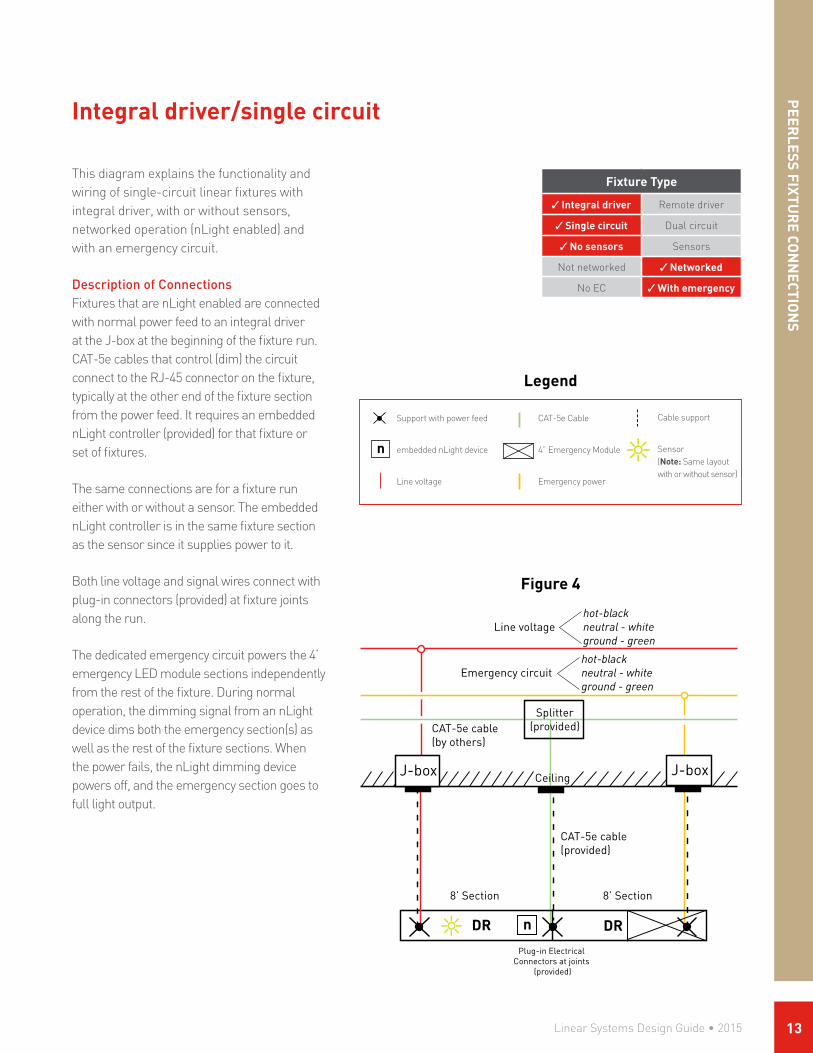
Figure 4
This diagram explains the functionality and wiring of single-circuit linear fixtures with integral driver, with or without sensors, networked operation (nLight enabled) and with an emergency circuit.
Description of ConnectionsFixtures that are nLight enabled are connected with normal power feed to an integral driver at the J-box at the beginning of the fixture run. CAT-5e cables that control (dim) the circuit connect to the RJ-45 connector on the fixture, typically at the other end of the fixture section from the power feed. It requires an embedded nLight controller (provided) for that fixture or set of fixtures.
The same connections are for a fixture run either with or without a sensor. The embedded nLight controller is in the same fixture section as the sensor since it supplies power to it.
Both line voltage and signal wires connect with plug-in connectors (provided) at fixture joints along the run.
The dedicated emergency circuit powers the 4’ emergency LED module sections independently from the rest of the fixture. During normal operation, the dimming signal from an nLight device dims both the emergency section(s) as well as the rest of the fixture sections. When the power fails, the nLight dimming device powers off, and the emergency section goes to full light output.
Line voltagehot-blackneutral - whiteground - green
Ceiling
8’ Section 8’ Section
Plug-in Electrical Connectors at joints
(provided)
CAT-5e cable(by others)
n DR
CAT-5e cable(provided)
Splitter(provided)
DR
Emergency circuithot-blackneutral - whiteground - green
Integral driver/single circuit
PEER
LESS FIXTUR
E CON
NECTIO
NS
Legend
Support with power feed
embedded nLight device
Line voltage
n
CAT-5e Cable
4” Emergency Module
Emergency power
Cable support
Sensor (Note: Same layout with or without sensor)
Linear Systems Design Guide • 2015 13

PEE
RLE
SS F
IXTU
RE
CON
NEC
TIO
NS
This diagram explains the functionality and wiring of dual-circuit linear fixtures with integral driver, no sensors, no networking (not nLight enabled) and no emergency circuit.
Description of ConnectionsDual-circuit fixtures are connected with normal power feed to an integral drivers at the J-box at the beginning of the fixture run. The 2 circuits share neutral and ground wires, and have separate hot wires, all contained within a single cord. There are 2 sets of 0–10V wires to control the uplight independently of the downlight. One set of control wires is purple/gray and the other is blue/white-blue, and both are provided as standard with connections at the drivers. They typically connect at the end of the fixture run opposite the power feed.
Both line voltage and signal wires connect with plug-in connectors (provided) at fixture joints along the run.
Fixture Type
Integral driver Remote driver
Single circuit Dual circuit
No sensors Sensors
Not networked Networked
No EC With emergency
Figure 5
Integral driver/dual circuit
Ceiling
Line voltage 1 Hot-black (uplight) Hot-red (downlight) Line voltage 2
(purple/gray)0-10V Controls Up
(blue/blue-white)0-10V Controls DN
8’ Section 8’ Section
Single Cord
Plug-in Electrical Connectors at joints
(provided)
Neutral - whiteGround - greenShared
Legend
Support with power feed
Support only
Line voltage
Cable support
0-10V Control Wires
Linear Systems Design Guide • 201514

Fixture Type
Integral driver Remote driver
Single circuit Dual circuit
No sensors Sensors
Not networked Networked
No EC With emergency
Figure 6
This diagram explains the functionality and wiring of dual-circuit linear fixtures with integral driver, no sensors, no networking (not nLight enabled) and with an emergency circuit.
Description of ConnectionsDual-circuit fixtures that are connected with normal power feed to integral drivers at the J-box at the beginning of the fixture run. The 2 circuits share neutral and ground wires, and have separate hot wires, all contained within a single cord. There are 2 sets of 0–10V wires to control the uplight independently of the downlight. One set of control wires is purple/gray and the other is blue/white-blue, and both are provided as standard with connections at the drivers. They typically connect at the end of the fixture run opposite the power feed.
The dedicated emergency circuit powers the 4’ downlight emergency section independently from the rest of the fixture. Separate feed drop for each emergency section is required for most local codes. During normal operation, the dimming level from the 0-10V signal dims both the emergency section as well as the rest of the fixture sections. When the power fails, the dimming signals powers off, and the emergency section goes to full light output.
Both line voltage and signal wires connect with plug-in connectors (provided) at fixture joints along the run.
Integral driver/dual circuit
Ceiling
Neutral - WhiteGround - Green
Shared
Line Voltage 1 Hot-black (uplight) Hot-red (downlight) Line Voltage 2
UP (purple/gray)0-10V Controls 1
DN (blue/blue-white)0-10V Controls 2
(uplight)
(downlight)
8’ Section 8’ Section
Plug-in Electrical Connectors at joints
(provided)
hot-blackneutral-whiteground-green
Emergency circuit
PEER
LESS FIXTUR
E CON
NECTIO
NS
Legend
Support with power feed
Support only
Line voltage
Emergency power
Cable support
0-10V Control Wires
Linear Systems Design Guide • 2015 15

PEE
RLE
SS F
IXTU
RE
CON
NEC
TIO
NS
Legend
This diagram explains the functionality and wiring of dual-circuit linear fixtures with integral driver, with or without sensors, networked operation (nLight enabled) and no emergency circuit.
Description of ConnectionsDual-circuit fixtures that are nLight enabled are connected with a single normal power feed to integral drivers at the J-box at the beginning of the fixture run. A single CAT-5e cable carries control signals to both embedded nLight controllers (connected internally), to the uplight driver and the downlight driver independently. The cable connects via an RJ-45 connector on the fixture, typically at the other end of the fixture section from the power feed.
The same connections shown here are for a fixture run either with or without a sensor. There is an embedded nLight controller in the same fixture section as the sensor since it supplies power to it.
Both line voltage and signal wires connect with plug-in connectors (provided) at fixture joints along the run.
Fixture Type
Integral driver Remote driver
Single circuit Dual circuit
No sensors Sensors
Not networked Networked
No EC With emergency
Integral driver/dual circuit
Line voltagehot-blackneutral - whiteground - green
Ceiling
8’ Section 8’ Section
Plug-in Electrical Connectors at joints
(provided)
CAT-5e cable(by others)
CAT-5e cable(provided)
Splitter(provided)
to other nLight devices
n
n(uplight)
(downlight)
Support with power feed
Support only
n embedded nLight device
Line voltage
CAT-5e Cable
Cable support
Figure 7
Linear Systems Design Guide • 201516

Fixture Type
Integral driver Remote driver
Single circuit Dual circuit
No sensors Sensors
Not networked Networked
No EC With emergency
Figure 8
This diagram explains the functionality and wiring of dual-circuit linear fixtures with integral driver, no sensors, networked operation (nLight enabled) and with an emergency circuit.
Description of ConnectionsDual-circuit fixtures that are nLight enabled are connected with a single normal power feed to integral drivers at the J-box at the beginning of the fixture run. A single CAT-5e cable carries control signals to both embedded nLight controllers (connected internally), to the uplight driver and the downlight driver independently. The cable connects via an RJ-45 connector on the fixture, typically at the other end of the fixture section from the power feed.
The same connections shown here are for a fixture run either with or without a sensor. There is an embedded nLight controller must be is in the same fixture section as the sensor since it supplies power to it.
The dedicated emergency circuit powers the 4’ downlight emergency LED module sections independently from the rest of the fixture. During normal operation, the CAT-5e signal from an nLight device dims both the emergency section(s) as well as the rest of the fixture sections. When the power fails, the nLight dimming device powers off, and the emergency section goes to full light output.
Both line voltage and signal wires connect with plug-in connectors (provided) at fixture joints along the run.
Integral driver/dual circuit
Line voltagehot-blackneutral - whiteground - green
Ceiling
8’ Section 8’ Section
CAT-5e cable(by others)
CAT-5e cable(provided)
Splitter(provided)
Emergency circut
n
n
Plug-in Electrical Connectors at joints
(provided)
hot-blackneutral-whiteground-green
PEER
LESS FIXTUR
E CON
NECTIO
NS
Support with power feed
embedded nLight device
Line voltage
n
CAT-5e Cable
Emergency Section
Emergency power
Cable support
Sensor
Legend
Linear Systems Design Guide • 2015 17
PEE
RLE
SS F
IXTU
RE
CON
NEC
TIO
NS
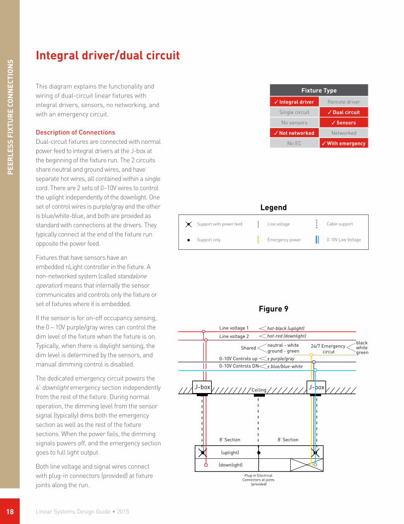
This diagram explains the functionality and wiring of dual-circuit linear fixtures with integral drivers, sensors, no networking, and with an emergency circuit.
Description of ConnectionsDual-circuit fixtures are connected with normal power feed to integral drivers at the J-box at the beginning of the fixture run. The 2 circuits share neutral and ground wires, and have separate hot wires, all contained within a single cord. There are 2 sets of 0–10V wires to control the uplight independently of the downlight. One set of control wires is purple/gray and the other is blue/white-blue, and both are provided as standard with connections at the drivers. They typically connect at the end of the fixture run opposite the power feed.
Fixtures that have sensors have an embedded nLight controller in the fixture. A non-networked system (called standalone operation) means that internally the sensor communicates and controls only the fixture or set of fixtures where it is embedded.
If the sensor is for on-off occupancy sensing, the 0 – 10V purple/gray wires can control the dim level of the fixture when the fixture is on. Typically, when there is daylight sensing, the dim level is determined by the sensors, and manual dimming control is disabled.
The dedicated emergency circuit powers the 4’ downlight emergency section independently from the rest of the fixture. During normal operation, the dimming level from the sensor signal (typically) dims both the emergency section as well as the rest of the fixture sections. When the power fails, the dimming signals powers off, and the emergency section goes to full light output.
Both line voltage and signal wires connect with plug-in connectors (provided) at fixture joints along the run.
Fixture Type
Integral driver Remote driver
Single circuit Dual circuit
No sensors Sensors
Not networked Networked
No EC With emergency
Figure 9
Integral driver/dual circuit
neutral - whiteground - green
Ceiling
Shared 24/7 Emergency circut
Line voltage 1 hot-black (uplight) hot-red (downlight) Line voltage 2
± purple/gray 0-10V Controls up
± blue/blue-white0-10V Controls DN
(uplight)
(downlight)
8’ Section 8’ Section
blackwhitegreen
Plug-in Electrical Connectors at joints
(provided)
Legend
Support with power feed
Support only
Line voltage
Emergency power
Cable support
0-10V Low Voltage
Linear Systems Design Guide • 201518
PEER
LESS FIXTUR
E CON
NECTIO
NS
Fixture Type
Integral driver Remote driver
Single circuit Dual circuit
No sensors Sensors
Not networked Networked
No EC With emergency
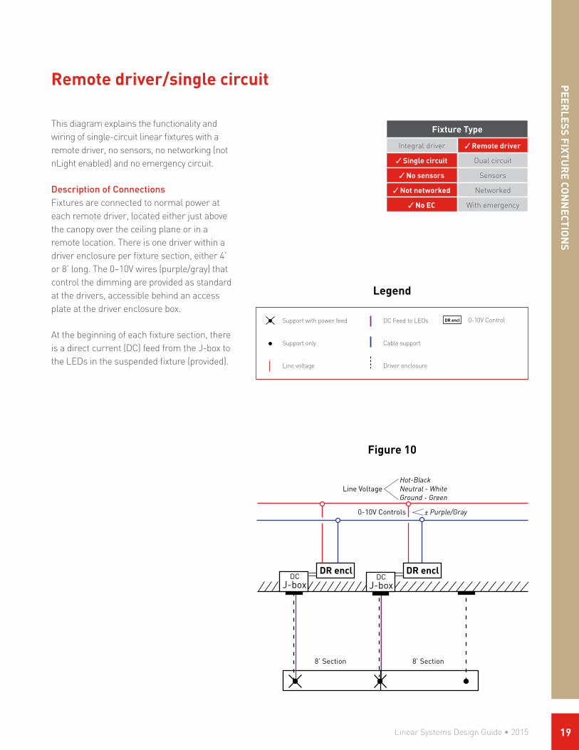
This diagram explains the functionality and wiring of single-circuit linear fixtures with a remote driver, no sensors, no networking (not nLight enabled) and no emergency circuit.
Description of ConnectionsFixtures are connected to normal power at each remote driver, located either just above the canopy over the ceiling plane or in a remote location. There is one driver within a driver enclosure per fixture section, either 4’ or 8’ long. The 0–10V wires (purple/gray) that control the dimming are provided as standard at the drivers, accessible behind an access plate at the driver enclosure box.
At the beginning of each fixture section, there is a direct current (DC) feed from the J-box to the LEDs in the suspended fixture (provided).
Remote driver/single circuit
Line VoltageHot-BlackNeutral - WhiteGround - Green
8’ Section 8’ Section
DR encl DR encl
± Purple/Gray 0-10V Controls
DCDC
Figure 10
Legend
Support with power feed
Support only
Line voltage
DR enclDC Feed to LEDs
Cable support
Driver enclosure
0-10V Control
Linear Systems Design Guide • 2015 19
PEE
RLE
SS F
IXTU
RE
CON
NEC
TIO
NS
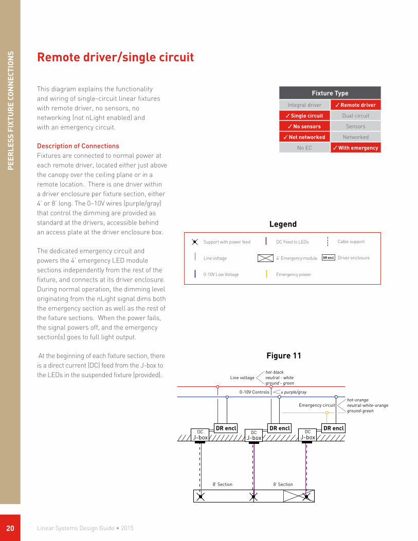
Figure 11
This diagram explains the functionality and wiring of single-circuit linear fixtures with remote driver, no sensors, no networking (not nLight enabled) and with an emergency circuit.
Description of ConnectionsFixtures are connected to normal power at each remote driver, located either just above the canopy over the ceiling plane or in a remote location. There is one driver within a driver enclosure per fixture section, either 4’ or 8’ long. The 0–10V wires (purple/gray) that control the dimming are provided as standard at the drivers, accessible behind an access plate at the driver enclosure box.
The dedicated emergency circuit and powers the 4’ emergency LED module sections independently from the rest of the fixture, and connects at its driver enclosure. During normal operation, the dimming level originating from the nLight signal dims both the emergency section as well as the rest of the fixture sections. When the power fails, the signal powers off, and the emergency section(s) goes to full light output.
At the beginning of each fixture section, there is a direct current (DC) feed from the J-box to the LEDs in the suspended fixture (provided).
Fixture Type
Integral driver Remote driver
Single circuit Dual circuit
No sensors Sensors
Not networked Networked
No EC With emergency
Remote driver/single circuit
Line voltagehot-blackneutral - whiteground - green
8’ Section 8’ Section
Emergency circuit
DR encl DR encl
± purple/gray 0-10V Controls
DR enclDC DC DC
hot-orangeneutral-white-orangeground-green
Legend
Support with power feed
Line voltage
0-10V Low Voltage
DR encl
DC Feed to LEDs
4’ Emergency module
Emergency power
Cable support
Driver enclosure
Linear Systems Design Guide • 201520
Fixture Type
Integral driver Remote driver
Single circuit Dual circuit
No sensors Sensors
Not networked Networked
No EC With emergency
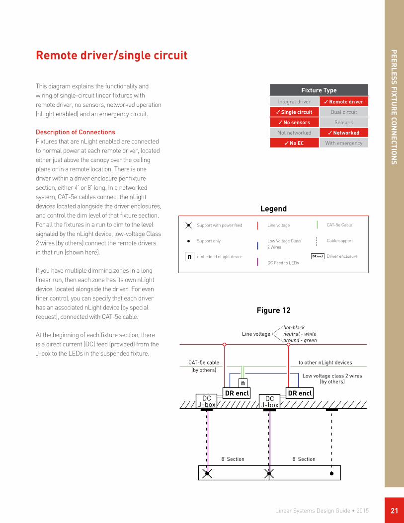
This diagram explains the functionality and wiring of single-circuit linear fixtures with remote driver, no sensors, networked operation (nLight enabled) and an emergency circuit.
Description of ConnectionsFixtures that are nLight enabled are connected to normal power at each remote driver, located either just above the canopy over the ceiling plane or in a remote location. There is one driver within a driver enclosure per fixture section, either 4’ or 8’ long. In a networked system, CAT-5e cables connect the nLight devices located alongside the driver enclosures, and control the dim level of that fixture section. For all the fixtures in a run to dim to the level signaled by the nLight device, low-voltage Class 2 wires (by others) connect the remote drivers in that run (shown here).
If you have multiple dimming zones in a long linear run, then each zone has its own nLight device, located alongside the driver. For even finer control, you can specify that each driver has an associated nLight device (by special request), connected with CAT-5e cable.
At the beginning of each fixture section, there is a direct current (DC) feed (provided) from the J-box to the LEDs in the suspended fixture.
Remote driver/single circuit
Line voltagehot-blackneutral - whiteground - green
8’ Section 8’ Section
CAT-5e cable(by others)
DR encl
to other nLight devices
Low voltage class 2 wires(by others)
DR encln
DCDC
PEER
LESS FIXTUR
E CON
NECTIO
NS
Figure 12
Legend
Support with power feed
Support only
embedded nLight devicen DR encl
Line voltage
Low Voltage Class 2 Wires
DC Feed to LEDs
CAT-5e Cable
Cable support
Driver enclosure
Linear Systems Design Guide • 2015 21

PEE
RLE
SS F
IXTU
RE
CON
NEC
TIO
NS
Legend
This diagram explains the functionality and wiring of single-circuit linear fixtures with remote driver, no sensors, networked operation (nLight enabled) and an emergency circuit.
Description of ConnectionsFixtures that are nLight enabled are connected to normal power at each remote driver, located either just above the canopy over the ceiling plane or in a remote location. There is one driver within a driver enclosure per fixture section, either 4’ or 8’ long. In a networked system, CAT-5e cables connect the nLight devices located alongside the driver enclosures, and control the dim level of those fixture sections. For all the fixtures in a run to dim to the level signaled by the nLight device, low-voltage Class 2 wires (by others) connect the remote drivers in that run (shown here).
If you have multiple dimming zones in a long linear run, then each zone has its own nLight device, located alongside the driver. For even finer control, you can specify that each driver has an associated nLight device (by special request), and connections between nLight devices will be with CAT-5e cable (by others) instead of low-voltage wires.
The dedicated emergency circuit powers the 4’ emergency LED module sections independently from the rest of the fixture, and connects at its driver enclosure. During normal operation, the dimming level originating from the nLight signal dims both the emergency section as well as the rest of the fixture sections. When the power fails, the signal powers off, and the emergency section(s) goes to full light output.
At the beginning of each fixture section, there is a direct current (DC) feed (provided) from the J-box to the LEDs in the suspended fixture.
Fixture Type
Integral driver Remote driver
Single circuit Dual circuit
No sensors Sensors
Not networked Networked
No EC With emergency
Remote driver/single circuit
Line voltagehot-blackneutral - whiteground - green
8’ Section 8’ Section
Emergency circut
CAT-5e cable(by others)
DR encl
to other nLight devices
Low voltage class 2 wires(by others)
DR encl DR encln
hot-orangeneutral - orange-whiteground - green
DC DCDC
Figure 13
Support with power feed
nLight device
Line voltage
Low voltage class 2 wires
n DR encl
DC Feed to LEDs
CAT-5e Cable
Emergency Section
Emergency power
Cable support
Driver enclosure
Linear Systems Design Guide • 201522
Fixture Type
Integral driver Remote driver
Single circuit Dual circuit
No sensors Sensors
Not networked Networked
No EC With emergency
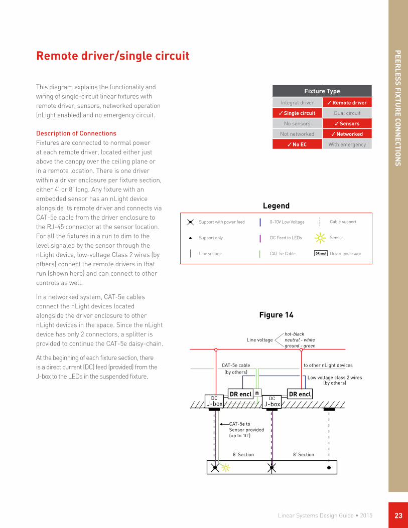
Figure 14
This diagram explains the functionality and wiring of single-circuit linear fixtures with remote driver, sensors, networked operation (nLight enabled) and no emergency circuit.
Description of ConnectionsFixtures are connected to normal power at each remote driver, located either just above the canopy over the ceiling plane or in a remote location. There is one driver within a driver enclosure per fixture section, either 4’ or 8’ long. Any fixture with an embedded sensor has an nLight device alongside its remote driver and connects via CAT-5e cable from the driver enclosure to the RJ-45 connector at the sensor location. For all the fixtures in a run to dim to the level signaled by the sensor through the nLight device, low-voltage Class 2 wires (by others) connect the remote drivers in that run (shown here) and can connect to other controls as well.
In a networked system, CAT-5e cables connect the nLight devices located alongside the driver enclosure to other nLight devices in the space. Since the nLight device has only 2 connectors, a splitter is provided to continue the CAT-5e daisy-chain.
At the beginning of each fixture section, there is a direct current (DC) feed (provided) from the J-box to the LEDs in the suspended fixture.
Remote driver/single circuit
CAT-5e cable(by others)
to other nLight devices
Line voltagehot-blackneutral - whiteground - green
8’ Section 8’ Section
DR enclDR enclDCDC
CAT-5e to Sensor provided(up to 10’)
Low voltage class 2 wires(by others)
n
PEER
LESS FIXTUR
E CON
NECTIO
NS
Legend
Support with power feed
Support only
Line voltage DR encl
0-10V Low Voltage
DC Feed to LEDs
CAT-5e Cable
Cable support
Sensor
Driver enclosure
Linear Systems Design Guide • 2015 23

PEE
RLE
SS F
IXTU
RE
CON
NEC
TIO
NS
Legend
This diagram explains the functionality and wiring of single-circuit linear fixtures with remote driver, sensors, networked operation (nLight enabled) and an emergency circuit.
Description of ConnectionsFixtures that are nLight enabled are connected to normal power at each remote driver, located either just above the canopy over the ceiling plane or in a remote location. There is one driver within a driver enclosure per fixture section, either 4’ or 8’ long. Any fixture with an embedded sensor has an nLight device alongside its remote driver and connects via CAT-5e cable from the driver enclosure to the RJ-45 connector at the sensor location. For all the fixtures in a run to dim to the level signaled by the sensor through the nLight device, low-voltage Class 2 wires (by others) connect the remote drivers in that run (shown here). (Dimming signal can be passed to other drivers in the run via CAT-5e cable but require more nLight devices. Available by special request.)
In a networked system, CAT-5e cables connect the nLight devices located alongside the driver enclosure to other nLight devices in the space. Since the nLight device has only 2 connectors, a splitter is provided to continue the CAT-5e daisy-chain.
At the beginning of each fixture section, there is a direct current (DC) feed (provided) from the J-box to the LEDs in the suspended fixture.
The dedicated emergency circuit powers the 4’ emergency LED module sections independently from the rest of the fixture, and connects at its driver enclosure. During normal operation, the dimming level originating from the nLight signal dims both the emergency section as well as the rest of the fixture sections. When the power fails, the signal powers off, and the emergency section(s) goes to full light output.
Fixture Type
Integral driver Remote driver
Single circuit Dual circuit
No sensors Sensors
Not networked Networked
No EC With emergency
Remote driver/single circuit
Line voltagehot-blackneutral - whiteground - green
8’ Section 8’ Section
n
CAT-5e cable(by others)
DR encl
Low voltageClass 2 wires
(by others)
DR encl DR encl
Splitter(provided)
DC DC DC
Emergency circuthot-orangeneutral-white-orangeground-green
CAT-5e to Sensor provided(up to 10’)
Figure 15
Support with power feed
embedded nLight device
Line voltage
DC Feed to LEDs
n DR encl
CAT-5e Cable
4’ Emergency module
Emergency power
Cable support
Sensor
Driver enclosure
0-10V Control
Linear Systems Design Guide • 201524

Fixture Type
Integral driver Remote driver
Single circuit Dual circuit
No sensors Sensors
Not networked Networked
No EC With emergency
This diagram explains the functionality and wiring of dual-circuit linear fixtures with remote drivers, no sensors, no networking (not nLight enabled) and no emergency circuit.
Description of ConnectionsDual-circuit fixtures are connected with normal power feeds to remote drivers, located in a driver enclosure either just above the canopy over the ceiling plane or in a remote location. There are two or more drivers within a driver enclosure per fixture section, either 4’ or 8’ long. The 2 circuits share neutral and ground wires, and have separate hot wires. There are 2 sets of 0–10V wires to control the uplight independently of the downlight. One set of control wires is purple/gray and the other is blue/white-blue, and both are provided as standard with connections at the remote driver enclosures, accessible behind an access plate.
Two direct current (DC) feeds from the remote drivers drop in a single cord to the fixture and power the LEDs in the uplight and downlight components of the suspended fixture independently.
Remote driver/dual circuit
Line voltage 1
± blue/blue-white
DR encl
± purple/gray
hot-red (downlight) hot-black (uplight)
DR encl
Line voltage 2
0-10V controls UP
0-10V controls DN
8’ Section 8’ Section
(downlight)
(uplight)
DCDC
Shared neutral-whiteground-green
PEER
LESS FIXTUR
E CON
NECTIO
NS
Legend
Support with power feed
Support only
Line voltage DR encl
DC Feed to LEDs
Cable support
Driver enclosure
0-10V Control Wires
Figure 16
Linear Systems Design Guide • 2015 25

PEE
RLE
SS F
IXTU
RE
CON
NEC
TIO
NS
This diagram explains the functionality and wiring of dual-circuit linear fixtures with remote drivers, no sensors, no networking (not nLight enabled) and an emergency circuit.
Description of ConnectionsDual-circuit fixtures are connected with normal power feeds to remote drivers, located in a driver enclosure either just above the canopy over the ceiling plane or in a remote location. There are two or more drivers within a driver enclosure per fixture section, either 4’ or 8’ long. The 2 circuits share neutral and ground wires, and have separate hot wires. There are 2 sets of 0–10V wires to control the uplight independently of the downlight. One set of control wires is purple/gray and the other is blue/white-blue, and both are provided as standard with connections at the remote driver enclosures, accessible behind an access plate.
Two direct current (DC) feeds from the remote drivers drop in a single cord to the fixture and power the LEDs in the uplight and downlight components of the suspended fixture independently.
The dedicated emergency circuit powers the 4’ downlight emergency LED module sections independently from the rest of the fixture, and connects at its driver enclosure. During normal operation, the dimming level from the 0-10V signal dims both the emergency section as well as the rest of the fixture sections. When the power fails, the signal powers off, and the emergency section(s) goes to full light output.
Fixture Type
Integral driver Remote driver
Single circuit Dual circuit
No sensors Sensors
Not networked Networked
No EC With emergency
Figure 17
Remote driver/dual circuit
Line voltage 1
± blue/blue-white
DR encl DR encl
± purple/gray
hot-red (downlight) hot-black (uplight)
DR encl
Line voltage 2
0-10V controls UP
0-10V controls DN
Shared neutral-whiteground-green
DC DC DC
Emergency circuthot-orangeneutral-white-orangeground-green
Legend
Support with power feed
Line voltage
DC Feed to LEDs
DR encl4’ Emergency Section
Emergency power
Cable support
Driver enclosure
0-10V Control Wires
Linear Systems Design Guide • 201526

Fixture Type
Integral driver Remote driver
Single circuit Dual circuit
No sensors Sensors
Not networked Networked
No EC With emergency
Figure 18
This diagram explains the functionality and wiring of dual-circuit linear fixtures with remote drivers, no sensors, networked operation (nLight enabled) and no emergency circuit.
Description of ConnectionsDual-circuit fixtures that are nLight enabled are connected to with a single normal power feed to remote drivers, located in a driver enclosure either just above the canopy over the ceiling plane or in a remote location. There are two or more drivers within a driver enclosure per fixture section, either 4’ or 8’ long. In a networked system, CAT-5e cables (by others) connect to the two nLight devices located alongside the driver enclosures of the first fixture at the beginning of a run (with up to 10’ CAT-5e cable provided). All connections are via a set of RJ-45 connectors at the nLight device. Two sets of low-voltage Class 2 wires (by others) connect the first remote driver enclosure to the other driver enclosures of the run to dim both the uplight and the downlight to the levels signaled by the nLight devices.
At the beginning of each fixture section, two direct current (DC) feeds from the J-box drop in a single cord to the suspended fixture and power the LEDs in the uplight and downlight components independently.
Remote driver/dual circuit
Line voltagehot-blackneutral - whiteground - green
UP (purple/gray)DN (blue/blue-white)
8’ Section 8’ Section
n n
CAT-5e cable(by others)
DR encl
Provided
to other nLight devices
0-10V controls
(by others)
DR encl
Up Dn
(downlight)
(uplight)
DC DC
PEER
LESS FIXTUR
E CON
NECTIO
NS
Legend
Support with power feed
Support only
embedded nLight devicen
DR encl
Line voltage
DC Feed to LEDs
CAT-5e Cable
Cable support
Driver enclosure
0-10V Controls (separate for uplight vs downlight)
Linear Systems Design Guide • 2015 27

PEE
RLE
SS F
IXTU
RE
CON
NEC
TIO
NS
Figure 19
This diagram explains the functionality and wiring of dual-circuit linear fixtures with remote drivers, no sensors, networked operation (nLight enabled) and an emergency circuit.
Description of ConnectionsDual-circuit fixtures that are nLight enabled are connected with a single normal power feed to remote drivers, located in a driver enclosure either just above the canopy over the ceiling plane or in a remote location. There are two or more drivers within a driver enclosure per fixture section, either 4’ or 8’ long. In a networked system, CAT-5e cables (by others) connect to the two nLight devices located alongside the driver enclosures of the first fixture at the beginning of a run (with up to 10’ CAT-5e cable provided). All connections are via a set of RJ-45 connectors at the nLight device. Two sets of low-voltage Class 2 wires (by others) connect the first remote driver enclosure to the other driver enclosures of the run to dim both the uplight and the downlight to the levels signaled by the nLight devices.
At the beginning of each fixture section, two direct current (DC) feeds from the J-box drop in a single cord to the suspended fixture and power the LEDs in the uplight and downlight components independently.
The a dedicated emergency circuit powers the 4’ downlight emergency LED module sections independently from the rest of the fixture, and connects at its driver enclosure. During normal operation, the dimming level originating from the nLight signal dims both the emergency section as well as the rest of the fixture sections. When the power fails, the signal powers off, and the emergency section(s) goes to full light output.
Fixture Type
Integral driver Remote driver
Single circuit Dual circuit
No sensors Sensors
Not networked Networked
No EC With emergency
Remote driver/dual circuit
Line VoltageHot-BlackNeutral - WhiteGround - Green
8’ Section 8’ Section
n n
CAT-5e cable(by others)
DR encl
Provided
to other nLight devices
0-10V controls(by others)
DR encl DR encl
Up Dn
(downlight)
(uplight)
Emergency circuthot-orangeneutral-white-orangeground-green
DC DC DC
UP (purple/gray)DN (blue/blue-white)
Legend
Support with power feed
embedded nLight device
Line voltage
DC Feed to LEDs
n
DR enclCAT-5e Cable
4’ Emergency Module
Emergency power
Cable support
Driver enclosure
0-10V Control Wires (separate for uplight vs downlight)
Linear Systems Design Guide • 201528

PEER
LESS FIXTUR
E CON
NECTIO
NS
Fixture Type
Integral driver Remote driver
Single circuit Dual circuit
No sensors Sensors
Not networked Networked
No EC With emergency
This diagram explains the functionality and wiring of dual-circuit linear fixtures with remote drivers, sensors, networked operation (nLight enabled) and no emergency circuit.
Description of ConnectionsDual-circuit fixtures that are nLight enabled are connected with a single normal power feed to remote drivers, located in a driver enclosure either just above the canopy over the ceiling plane or in a remote location. There are two or more drivers within a driver enclosure per fixture section, either 4’ or 8’ long. Any dual-circuit fixture with an embedded sensor has two nLight devices alongside its remote driver enclosure and one connects via CAT-5e cable to the RJ-45 connector at the sensor location (with up to 10’ CAT-5e cable provided). For all the fixtures in a run to dim to the level signaled by the sensor, two sets of low-voltage Class 2 wires (by others) connect the first remote driver enclosure to the other driver enclosures of the run to dim both the uplight and the downlight to the levels signaled by the nLight devices. (Dimming signal can be passed to other drivers in the run via CAT-5e cable but require more nLight devices. Available by special request.)
In a networked system, CAT-5e cables connect the nLight devices located alongside the driver enclosure to other nLight devices in the space. Since the nLight device has only 2 connectors, a splitter is provided to continue the CAT-5e daisy-chain.
At the beginning of each fixture section, two direct current (DC) feeds from the J-box drop in a single cord to the suspended fixture and power the LEDs in the uplight and downlight components independently.
Remote driver/dual circuit
Line voltagehot-blackneutral - whiteground - green
8’ Section 8’ Section
CAT-5e to sensor provided(up to 10’)
Splitter
n n
CAT-5e cable(by others)
DR encl
Provided
to other nLight devices
0-10V controls(by others)
DR encl
Up Dn
(uplight)
(downlight)
UP (purple/gray)DN (blue/blue-white)
DC DC
Figure 20
Legend
Support with power feed
Support only
embedded nLight device
Line voltage
n
DR enclDC Feed to LEDs
CAT-5e Cable
Cable support
Sensor
Driver enclosure
0-10V Control Wires (separate for uplight vs downlight)
Linear Systems Design Guide • 2015 29
PEE
RLE
SS F
IXTU
RE
CON
NEC
TIO
NS
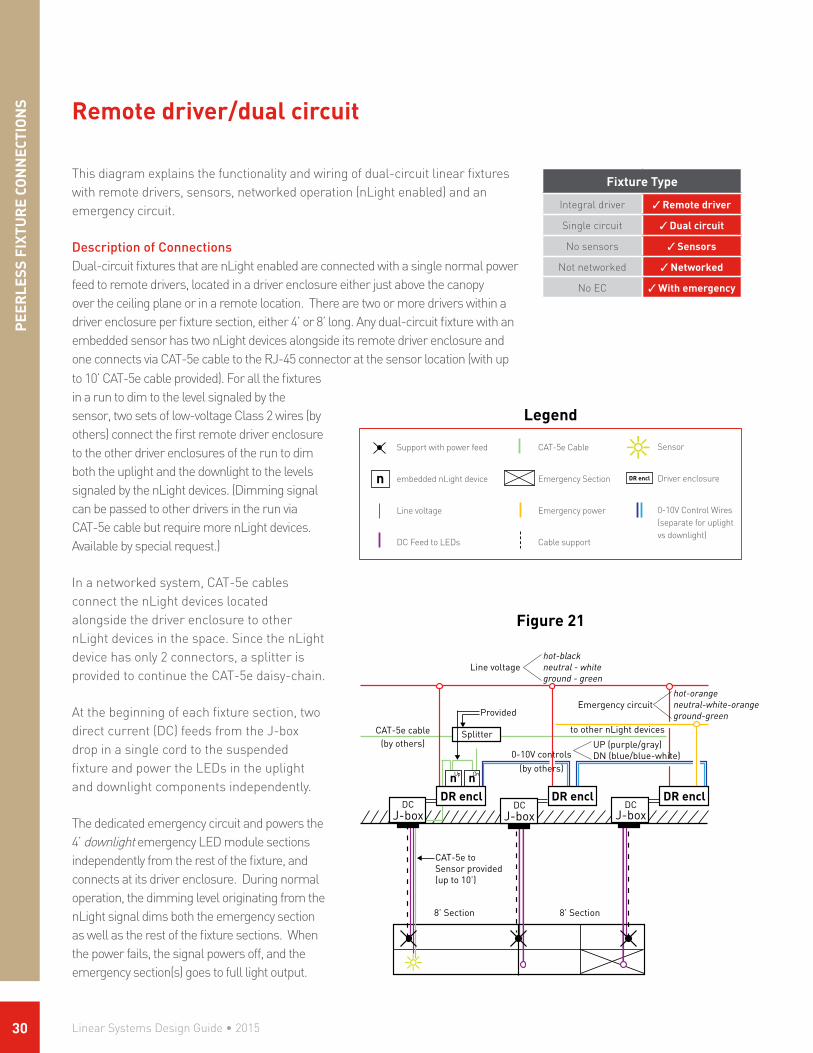
This diagram explains the functionality and wiring of dual-circuit linear fixtures with remote drivers, sensors, networked operation (nLight enabled) and an emergency circuit.
Description of ConnectionsDual-circuit fixtures that are nLight enabled are connected with a single normal power feed to remote drivers, located in a driver enclosure either just above the canopy over the ceiling plane or in a remote location. There are two or more drivers within a driver enclosure per fixture section, either 4’ or 8’ long. Any dual-circuit fixture with an embedded sensor has two nLight devices alongside its remote driver enclosure and one connects via CAT-5e cable to the RJ-45 connector at the sensor location (with up
Remote driver/dual circuit
Fixture Type
Integral driver Remote driver
Single circuit Dual circuit
No sensors Sensors
Not networked Networked
No EC With emergency
Line voltagehot-blackneutral - whiteground - green
8’ Section 8’ Section
CAT-5e to Sensor provided(up to 10’)
Splitter
n n
CAT-5e cable(by others)
DR encl
Provided
to other nLight devices
0-10V controls(by others)
DR encl DR encl
Up Dn
Emergency circuithot-orangeneutral-white-orangeground-green
UP (purple/gray)DN (blue/blue-white)
DC DC DC
Figure 21
to 10’ CAT-5e cable provided). For all the fixtures in a run to dim to the level signaled by the sensor, two sets of low-voltage Class 2 wires (by others) connect the first remote driver enclosure to the other driver enclosures of the run to dim both the uplight and the downlight to the levels signaled by the nLight devices. (Dimming signal can be passed to other drivers in the run via CAT-5e cable but require more nLight devices. Available by special request.)
In a networked system, CAT-5e cables connect the nLight devices located alongside the driver enclosure to other nLight devices in the space. Since the nLight device has only 2 connectors, a splitter is provided to continue the CAT-5e daisy-chain.
At the beginning of each fixture section, two direct current (DC) feeds from the J-box drop in a single cord to the suspended fixture and power the LEDs in the uplight and downlight components independently.
The dedicated emergency circuit and powers the 4’ downlight emergency LED module sections independently from the rest of the fixture, and connects at its driver enclosure. During normal operation, the dimming level originating from the nLight signal dims both the emergency section as well as the rest of the fixture sections. When the power fails, the signal powers off, and the emergency section(s) goes to full light output.
Legend
Support with power feed
embedded nLight device
Line voltage
DC Feed to LEDs
n DR encl
CAT-5e Cable
Emergency Section
Emergency power
Cable support
Sensor
Driver enclosure
0-10V Control Wires (separate for uplight vs downlight)
Linear Systems Design Guide • 201530
PEER
LESS FIXTUR
E CON
NECTIO
NS
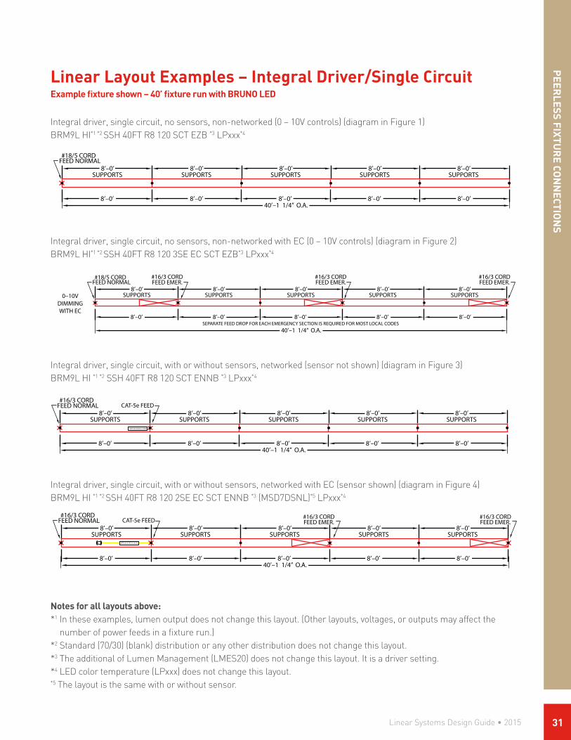
Notes for all layouts above:*1 In these examples, lumen output does not change this layout. (Other layouts, voltages, or outputs may affect the
number of power feeds in a fixture run.)*2 Standard (70/30) (blank) distribution or any other distribution does not change this layout.*3 The additional of Lumen Management (LMES20) does not change this layout. It is a driver setting.*4 LED color temperature (LPxxx) does not change this layout.*5 The layout is the same with or without sensor.
Linear Layout Examples – Integral Driver/Single CircuitExample fixture shown – 40’ fixture run with BRUNO LED
Integral driver, single circuit, no sensors, non-networked (0 – 10V controls) (diagram in Figure 1)BRM9L HI*1 *2 SSH 40FT R8 120 SCT EZB *3 LPxxx*4
FEED NORMAL#18/5 CORD
8’–0’ 8’–0’ 8’–0’ 8’–0’ 8’–0’
40’–1 1/4” O.A.
8’–0’SUPPORTS
8’–0’SUPPORTS
8’–0’SUPPORTS
8’–0’SUPPORTS
8’–0’SUPPORTS0–10V
DIMMINGWITH EC
#16/3 CORDFEED EMER.
#16/3 CORDFEED EMER.
#16/3 CORDFEED EMER.
SEPARATE FEED DROP FOR EACH EMERGENCY SECTION IS REQUIRED FOR MOST LOCAL CODES
FEED NORMAL#16/3 CORD
8’–0’40’–1 1/4” O.A.
8’–0’ 8’–0’ 8’–0’ 8’–0’
8’–0’SUPPORTS
8’–0’SUPPORTS
8’–0’SUPPORTS
8’–0’SUPPORTS
8’–0’SUPPORTS
CAT-5e FEED #16/3 CORDFEED EMER.
#16/3 CORDFEED EMER.
nEPS 60 IO EZ LC N100
FEED NORMAL#16/3 CORD
8’–0’40’–1 1/4” O.A.
8’–0’ 8’–0’ 8’–0’ 8’–0’
8’–0’SUPPORTS
8’–0’SUPPORTS
8’–0’SUPPORTS
8’–0’SUPPORTS
8’–0’SUPPORTS
CAT-5e FEED
nEPS 60 IO EZ LC N100
FEED NORMAL#18/5 CORD
8’–0’40’–1 1/4” O.A.
8’–0’ 8’–0’ 8’–0’ 8’–0’
8’–0’SUPPORTS
8’–0’SUPPORTS
8’–0’SUPPORTS
8’–0’SUPPORTS
8’–0’SUPPORTS
Integral driver, single circuit, with or without sensors, networked with EC (sensor shown) (diagram in Figure 4)BRM9L HI *1 *2 SSH 40FT R8 120 2SE EC SCT ENNB *3 (MSD7DSNL)*5 LPxxx*4
FEED NORMAL#18/5 CORD
8’–0’ 8’–0’ 8’–0’ 8’–0’ 8’–0’
40’–1 1/4” O.A.
8’–0’SUPPORTS
8’–0’SUPPORTS
8’–0’SUPPORTS
8’–0’SUPPORTS
8’–0’SUPPORTS0–10V
DIMMINGWITH EC
#16/3 CORDFEED EMER.
#16/3 CORDFEED EMER.
#16/3 CORDFEED EMER.
SEPARATE FEED DROP FOR EACH EMERGENCY SECTION IS REQUIRED FOR MOST LOCAL CODES
FEED NORMAL#16/3 CORD
8’–0’40’–1 1/4” O.A.
8’–0’ 8’–0’ 8’–0’ 8’–0’
8’–0’SUPPORTS
8’–0’SUPPORTS
8’–0’SUPPORTS
8’–0’SUPPORTS
8’–0’SUPPORTS
CAT-5e FEED #16/3 CORDFEED EMER.
#16/3 CORDFEED EMER.
nEPS 60 IO EZ LC N100
FEED NORMAL#16/3 CORD
8’–0’40’–1 1/4” O.A.
8’–0’ 8’–0’ 8’–0’ 8’–0’
8’–0’SUPPORTS
8’–0’SUPPORTS
8’–0’SUPPORTS
8’–0’SUPPORTS
8’–0’SUPPORTS
CAT-5e FEED
nEPS 60 IO EZ LC N100
FEED NORMAL#18/5 CORD
8’–0’40’–1 1/4” O.A.
8’–0’ 8’–0’ 8’–0’ 8’–0’
8’–0’SUPPORTS
8’–0’SUPPORTS
8’–0’SUPPORTS
8’–0’SUPPORTS
8’–0’SUPPORTS
Integral driver, single circuit, no sensors, non-networked with EC (0 – 10V controls) (diagram in Figure 2)BRM9L HI*1 *2 SSH 40FT R8 120 3SE EC SCT EZB*3 LPxxx*4
FEED NORMAL#18/5 CORD
8’–0’ 8’–0’ 8’–0’ 8’–0’ 8’–0’
40’–1 1/4” O.A.
8’–0’SUPPORTS
8’–0’SUPPORTS
8’–0’SUPPORTS
8’–0’SUPPORTS
8’–0’SUPPORTS0–10V
DIMMINGWITH EC
#16/3 CORDFEED EMER.
#16/3 CORDFEED EMER.
#16/3 CORDFEED EMER.
SEPARATE FEED DROP FOR EACH EMERGENCY SECTION IS REQUIRED FOR MOST LOCAL CODES
FEED NORMAL#16/3 CORD
8’–0’40’–1 1/4” O.A.
8’–0’ 8’–0’ 8’–0’ 8’–0’
8’–0’SUPPORTS
8’–0’SUPPORTS
8’–0’SUPPORTS
8’–0’SUPPORTS
8’–0’SUPPORTS
CAT-5e FEED #16/3 CORDFEED EMER.
#16/3 CORDFEED EMER.
nEPS 60 IO EZ LC N100
FEED NORMAL#16/3 CORD
8’–0’40’–1 1/4” O.A.
8’–0’ 8’–0’ 8’–0’ 8’–0’
8’–0’SUPPORTS
8’–0’SUPPORTS
8’–0’SUPPORTS
8’–0’SUPPORTS
8’–0’SUPPORTS
CAT-5e FEED
nEPS 60 IO EZ LC N100
FEED NORMAL#18/5 CORD
8’–0’40’–1 1/4” O.A.
8’–0’ 8’–0’ 8’–0’ 8’–0’
8’–0’SUPPORTS
8’–0’SUPPORTS
8’–0’SUPPORTS
8’–0’SUPPORTS
8’–0’SUPPORTS
Integral driver, single circuit, with or without sensors, networked (sensor not shown) (diagram in Figure 3)BRM9L HI *1 *2 SSH 40FT R8 120 SCT ENNB *3 LPxxx*4
FEED NORMAL#18/5 CORD
8’–0’ 8’–0’ 8’–0’ 8’–0’ 8’–0’
40’–1 1/4” O.A.
8’–0’SUPPORTS
8’–0’SUPPORTS
8’–0’SUPPORTS
8’–0’SUPPORTS
8’–0’SUPPORTS0–10V
DIMMINGWITH EC
#16/3 CORDFEED EMER.
#16/3 CORDFEED EMER.
#16/3 CORDFEED EMER.
SEPARATE FEED DROP FOR EACH EMERGENCY SECTION IS REQUIRED FOR MOST LOCAL CODES
FEED NORMAL#16/3 CORD
8’–0’40’–1 1/4” O.A.
8’–0’ 8’–0’ 8’–0’ 8’–0’
8’–0’SUPPORTS
8’–0’SUPPORTS
8’–0’SUPPORTS
8’–0’SUPPORTS
8’–0’SUPPORTS
CAT-5e FEED #16/3 CORDFEED EMER.
#16/3 CORDFEED EMER.
nEPS 60 IO EZ LC N100
FEED NORMAL#16/3 CORD
8’–0’40’–1 1/4” O.A.
8’–0’ 8’–0’ 8’–0’ 8’–0’
8’–0’SUPPORTS
8’–0’SUPPORTS
8’–0’SUPPORTS
8’–0’SUPPORTS
8’–0’SUPPORTS
CAT-5e FEED
nEPS 60 IO EZ LC N100
FEED NORMAL#18/5 CORD
8’–0’40’–1 1/4” O.A.
8’–0’ 8’–0’ 8’–0’ 8’–0’
8’–0’SUPPORTS
8’–0’SUPPORTS
8’–0’SUPPORTS
8’–0’SUPPORTS
8’–0’SUPPORTS
Linear Systems Design Guide • 2015 31

®
Lighting for PeoplePeerlessLighting.com®
SQUARE UP/DOWN DCT FIXTURE RUNS
0-10VDIMMING
8'-0"SUPPORTS
8'-0"
40'-2" O.A. RUN
A/B POWER
8'-0"
8'-0"
8'-0"
8'-0"
8'-0"
8'-0"
8'-0"
8'-0"
#16/4 CORD
SUPPORTS SUPPORTS SUPPORTS SUPPORTS
DCTA = UP-LIGHTB = DOWN-LIGHT
A/B DIM CTRL#18/4 CORD
PAGE 1
Linear Layout Examples – Integral Driver/Dual CircuitExample fixture shown – 40’ fixture run with Square I/D
Integral driver, dual circuit, no sensors, non-networked (0 – 10V controls) (diagram in Figure 5 and Figure 9)SQM4 LO/HI *1 40FT R8 120 EZB DCT *2 LPxxx*3
PEE
RLE
SS F
IXTU
RE
CON
NEC
TIO
NS
Integral driver, dual circuit, no sensors, non-networked (0-10V controls) emergency circuit (diagram in Figure 6)SQM4 LO/HI *1 40FT R8 120 EZB DCT *2 2SE EC LPxxx*3
Integral driver, dual circuit, with or without sensors, networked (diagram in Figure 7)SQM4 LO/HI *1 40FT R8 120 ENNB DCT *2 (MSD7DSNL) *4 Pxxx*3
Integral driver, dual circuit, with or without sensors, networked with EC (diagram in Figure 8)SQM4 LO/HI *1 40FT R8 120 ENNB DCT 2SE EC *2 Pxxx*3
Notes for all layouts above:*1 This LO/HI distribution or any other option for distribution does not change this layout.*2 The additional of Lumen Management (LMES20) does not change this layout. It is a driver setting.*3 LED color temperature (LPxxx) does not change this layout. *4 The layout is the same with or without sensor.
SINGLE CIRCUIT ZONE SHOWN, FOR MULTIPLE CONTROL ZONES, EACH ZONE REQUIRES SEPARATE POWER-PACKS AND CAT-5e DROP.
®
Lighting for PeoplePeerlessLighting.com®
SQUARE UP/DOWN DCT FIXTURE RUNS
8'-0"SUPPORTS
8'-0"
40'-2" O.A. RUN
A/B POWER
8'-0"
8'-0"
8'-0"
8'-0"
8'-0"
8'-0"
8'-0"
8'-0"
#16/4 CORD
SUPPORTS SUPPORTS SUPPORTS SUPPORTS
DCT
nLIGHTCONTROL A
B
A = UP-LIGHTB = DOWN-LIGHT
EMER POWER#16/3 CORD
EMER POWER#16/3 CORD
PAGE 2
SINGLE CIRCUIT ZONE SHOWN. FOR MULTIPLE CONTROL ZONES, EACH ZONE REQUIRES SEPARATE POWER-PACKS AND CAT5 DROP.nLIGHT POWER-PACKS AND CAT-5e DROP MUST BE INSTALLED IN THE SAME FIXTURE SECTION.
A/B DIM CTRL#18/4 CORD
®
Lighting for PeoplePeerlessLighting.com®
SQUARE UP/DOWN DCT FIXTURE RUNS
8'-0"SUPPORTS
8'-0"
40'-2" O.A. RUN
NORMAL FEED
8'-0"
8'-0"
8'-0"
8'-0"
8'-0"
8'-0"
8'-0"
8'-0"
#16/3 CORD
SUPPORTS SUPPORTS SUPPORTS SUPPORTS
CAT-5e FEED
DCT
nLIGHT SENSORNETWORK CONTROL
A
B
A = UP-LIGHTB = DOWN-LIGHT
PDT1 SENSOR
PAGE 3
SINGLE CONTROL ZONE SHOWN. FOR MULTIPLE CONTROL ZONES, EACH ZONE REQUIRES SEPARATE POWER-PACKS AND CAT-5e DROP.nLIGHT SENSOR, POWER-PACKS AND CAT-5e DROP MUST BE INSTALLED IN THE SAME FIXTURE SECTION.
nEPS 60 IO EZ LC N100 nEPS 60 IO EZ LC N100
nEPS 60 EZ IO LC N100 nEPS 60 EZ IO LC N100
®
Lighting for PeoplePeerlessLighting.com®
SQUARE UP/DOWN DCT FIXTURE RUNS
nLIGHTCONTROL
8'-0"SUPPORTS
8'-0"
40'-2" O.A. RUN
A/B POWER
8'-0"
8'-0"
8'-0"
8'-0"
8'-0"
8'-0"
8'-0"
8'-0"
#16/4 CORD
SUPPORTS SUPPORTS SUPPORTS SUPPORTS
DCT/ECA = UP-LIGHTB = DOWN-LIGHT
CAT-5e FEED EMER. POWER#16/3 CORD
DOWN-LIGHT LED BOARDFIXTURE-SECTION WITH
ON EMERGENCY CIRCUIT
EMER. POWER#16/3 CORD
PAGE 4
SEPARATE FEED DROP FOR EACH EMERGENCY SECTION IS REQUIRED FOR MOST LOCAL CODES
Linear Systems Design Guide • 201532

PEER
LESS FIXTUR
E CON
NECTIO
NS
Linear Layout Examples – Remote Driver/Single CircuitExample fixture shown – 40’ fixture run with Vellum linear
Remote driver, single circuit, no sensors, non-networked (0 – 10V controls) (diagram in Figure 10)VMM9 HI*1 *2 40FT R8 120 SCT EZB *3 LPxxx*4
Remote driver, single circuit, no sensors, non-networked with EC (0 – 10V controls) (diagram in Figure 11)VMM9 HI*1 *2 40FT R8 120 1SE EC SCT EZB *3 LPxxx*4
Remote driver, single circuit, sensors, networked (diagram in Figure 12) – shown here with the multiple nLight device optionVMM9 HI*1 *2 40FT R8 120 SCT ENNB MSD7DSNL *3 LPxxx*4
LOW-VOLTAGE LED& CAT-5e CABLE DROP
nLIGHT SENSORNETWORK CONTROL
EACH CONTROL ZONE REQUIRES A SEPARATE nLIGHT POWER-PACK, CAN BE CAT-5e CABLE LINKED TO SINGLE OR MULTIPLE CONTROL HUBS.EACH FIXTURE SECTION REQUIRES A SEPARATE LOW-VOLTAGE LED FEED DROP TO CONNECT TO REMOTE DRIVER BOX ABOVE THE CEILING.nLIGHT SENSOR AND CAT-5e CABLE DROP MUST BE INSTALLED AT THE SAME LOCATION.
®
®®
®
EACH CONTROL ZONE REQUIRES A SEPARATE nLIGHT POWER-PACK, CAN BE CAT-5e CABLE LINKED TO SINGLE OR MULTIPLE CONTROL HUBS. EACH FIXTURE SECTION REQUIRES A SEPARATE LOW-VOLTAGE LED FEED DROP TO CONNECT TO REMOTE DRIVER BOX ABOVE THE CEILING.
0-10VDIMMING
Remote driver, single circuit, sensors, networked with EC (diagram in Figure 13) – shown here with the multiple nLight device optionVMM9 HI*1 *2 40FT R8 120 2SE EC SCT ENNB MSD7DSNL *3 LPxxx*4
®
®
LOW-VOLTAGE LED& CAT-5e CABLE DROP
nLIGHT SENSORNETWORK CONTROL
WITH EC
EACH FIXTURE SECTION REQUIRES A SEPARATE LOW-VOLTAGE LED FEED DROP TO CONNECT TO REMOTE DRIVER BOX ABOVE THE CEILING.EACH CONTROL ZONE REQUIRES A SEPARATE nLIGHT POWER-PACK, CAN BE CAT-5e CABLE LINKED TO SINGLE OR MULTIPLE CONTROL HUBS.EACH EMERGENCY SECTION REQUIRES A SEPATATE LOW-VOLTAGE LED FEED DROP TO CONNECT TO EMERGENCY DRIVER BOX.nLIGHT SENSOR AND CAT-5e CABLE MUST BE INSTALLED AT THE SAME LOCATION.
Notes for all layouts above:*1 In these examples, lumen output does not change this layout. (Other layouts, voltages, or outputs may affect the
number of power feeds in a fixture run.)*2 Standard (60/40) (blank) distribution or any other distribution does not change the layout.*3 The additional of Lumen Management (LMES20) does not change the layout. It is a driver setting.*4 LED color temperature (LPxxx) does not change the layout.
Linear Systems Design Guide • 2015 33

PEE
RLE
SS F
IXTU
RE
CON
NEC
TIO
NS
Linear Layout Examples – Remote Driver/Dual CircuitExample fixture shown – 40’ fixture run with OPEN I/D
Remote driver, dual circuit, no sensors, non-networked (0 – 10V controls) (diagram in Figure 16)Example: OPM4 HI/HI *1 40FT R8 120 DCT EZB *2 LPxxx*3
®
®
Remote driver, dual circuit, no sensors, non-networked with EC (0 – 10V controls) (diagram in Figure 17)Example: OPM4 HI/HI *1 40FT R8 120 2SE EC DCT EZB *2 LPxxx*3
®
®
EACH CONTROL ZONE REQUIRES A SEPARATE nLIGHT POWER-PACK, CAN BE CAT-5e CABLE LINKED TO SINGLE OR MULTIPLE CONTROL HUBS.EACH FIXTURE SECTION REQUIRES A SEPARATE LOW-VOLTAGE FEED DROP TO CONNECT TO REMOTE DRIVER BOX ABOVE THE CEILING.EACH REMOTE DRIVER BOX CONTAINS TWO LED DRIVERS, ONE FOR UP-LIGHT, ONE FOR DOWN-LIGHT.nLIGHT CONTROL POWER-PACKS ARE ATTACHED TO OUTSIDE OF DRIVERS BOXES, WITH CAT-5e PLUG ON EACH END.
0-10VDIMMING
DCT EC
Linear Layout Examples – Remote Driver/Single CircuitExample fixture shown – 40’ fixture run with Vellum linear
Notes for all layouts above:*1 In these examples, lumen output does not change this layout. (Other layouts, voltages, or outputs may affect the
number of power feeds in a fixture run.)*2 Standard (60/40) (blank) distribution or any other distribution does not change the layout.*3 The additional of Lumen Management (LMES20) does not change the layout. It is a driver setting.*4 LED color temperature (LPxxx) does not change the layout.
Remote driver, single circuit, sensors, networked with EC (diagram in Figure 15) – shown here with the multiple nLight device optionVMM9 HI*1 *2 40FT R8 120 1SE EC SCT ENNB MSD7DSNL *3 LPxxx*4
nLIGHTCONTROL
Remote driver, single circuit, sensors, networked (diagram 14) – shown here with the multiple nLight device optionVMM9 HI*1 *2 40FT R8 120 SCT ENNB MSD7DSNL *3 LPxxx*4
LOW-VOLTAGE LED& CAT-5e CABLE DROP
nLIGHT SENSORNETWORK CONTROL
EACH CONTROL ZONE REQUIRES A SEPARATE nLIGHT POWER-PACK, CAN BE CAT-5e CABLE LINKED TO SINGLE OR MULTIPLE CONTROL HUBS.EACH FIXTURE SECTION REQUIRES A SEPARATE LOW-VOLTAGE LED FEED DROP TO CONNECT TO REMOTE DRIVER BOX ABOVE THE CEILING.nLIGHT SENSOR AND CAT-5e CABLE DROP MUST BE INSTALLED AT THE SAME LOCATION.
Linear Systems Design Guide • 201534

PEER
LESS FIXTUR
E CON
NECTIO
NS
Remote driver, dual circuit, no sensors, networked (diagram in Figure 18)Same layout for with sensor and networked when nLight device at sensor section connects to other nLight devices in network.Example: OPM4 HI/HI *1 40FT R8 120 DCT ENNB *2 LPxxx*3
®
®
nLIGHT SENSORNETWORK CONTROL
DCT
CAT-5e CABLE &LOW-VOLTAGE
LED CORD
CEILING TILE
EACH CONTROL ZONE REQUIRES A SEPARATE nLIGHT POWER-PACK, CAN BE CAT-5e CABLE LINKED TO SINGLE OR MULTIPLE CONTROL HUBS.EACH FIXTURE SECTION REQUIRES A SEPARATE LOW-VOLTAGE FEED DROP TO CONNECT TO REMOTE DRIVER BOX ABOVE THE CEILING.EACH REMOTE DRIVER BOX CONTAINS TWO LED DRIVERS, ONE FOR UP-LIGHT, ONE FOR DOWN-LIGHT.nLIGHT CONTROL POWER-PACKS ARE ATTACHED TO OUTSIDE OF DRIVERS BOXES, WITH CAT-5e PLUG ON EACH END.
Remote driver, dual circuit, no sensors, networked with EC (diagram in Figure 19)Example: OPM4 HI/HI *1 40FT R8 120 2SE EC DCT ENNB *2 LPxxx*3
®
®
nLIGHTCONTROL
DCT/EC
Notes for all layouts above:*1 In these examples, lumen output does not change this layout.
(Other layouts, voltages, or outputs may affect the number of power feeds in a fixture run.)*2 Standard (60/40) (blank) distribution or any other distribution does not change the layout.*3 The additional of Lumen Management (LMES20) does not change the layout. It is a driver setting.
Remote driver, dual circuit, sensors, networked (diagram in Figure 20)Example: OPM4 HI/HI *1 40FT R8 120 DCT ENNB MSD7DSNL *2 LPxxx*3
®
®
EACH CONTROL ZONE REQUIRES A SEPARATE nLIGHT POWER-PACK, CAN BE CAT-5e CABLE LINKED TO SINGLE OR MULTIPLE CONTROL HUBS.EACH FIXTURE SECTION REQUIRES A SEPARATE LOW-VOLTAGE FEED DROP TO CONNECT TO REMOTE DRIVER BOX ABOVE THE CEILING.EACH REMOTE DRIVER BOX CONTAINS TWO LED DRIVERS, ONE FOR UP-LIGHT, ONE FOR DOWN-LIGHT.nLIGHT CONTROL POWER-PACKS ARE ATTACHED TO OUTSIDE OF DRIVERS BOXES, WITH CAT-5e PLUG ON EACH END.
nLIGHT SENSORNETWORK CONTROL
DCT
Remote driver, dual circuit, sensors, networked with EC (diagram in Figure 21) Example: OPM4 HI/HI *1 40FT R8 120 2SE EC DCT ENNB MSD7DSNL *2 LPxxx*3
nLIGHT SENSORNETWORK CONTROL
DCT/EC
CEILING TILE
CAT-5e CABLE &LOW-VOLTAGE
LED CORD
EACH CONTROL ZONE REQUIRES A SEPARATE nLIGHT POWER-PACK, CAN BE CAT-5e CABLE LINKED TO SINGLE OR MULTIPLE CONTROL HUBS.EACH FIXTURE SECTION REQUIRES A SEPARATE LOW-VOLTAGE FEED DROP TO CONNECT TO REMOTE DRIVER BOX ABOVE THE CEILING.EACH REMOTE DRIVER BOX CONTAINS TWO LED DRIVERS, ONE FOR UP-LIGHT, ONE FOR DOWN-LIGHT.nLIGHT CONTROL POWER-PACKS ARE ATTACHED TO OUTSIDE OF DRIVERS BOXES, WITH CAT-5e PLUG ON EACH END.
Linear Systems Design Guide • 2015 35

Classroom Application
Peerless linear suspended luminaires and nLight controls work together to create environments that allow for daylight and occupancy sensing, and dimming control.
Occupancy sensors/networked – any sensor triggers lights on and keeps them on
Schedule of operationsIn this typical classroom, project requires on-off lighting control at entry door into the room. Once switched on, lighting controls sense occupancy and lights turn on. As long as any occupancy is sensed, lights remain on. If room is vacated, lights turn off after programmed amount of time (default is 10 minutes).
The teacher can control lights and dimming level from a dimmer/switch near teacher’s desk.
AP
PLI
CATI
ON
EXA
MP
LES
• Classroom size: 30’ x 30’• Ceiling height: 10’ • Mounting height of fixtures and sensors: 8’• Rows are 14’ OC
Solution• Circle shows range of sensing small motion for each fixture-
mounted sensor• The diameter of the coverage pattern for small motion using
nLight occupancy sensors embedded in the fixture is about 20’ for ceiling height.
• Walking movement coverage pattern is larger• Occupancy sensors are located in fixture run to cover classroom
area completely
sensor controller$ wall switch$D dimmer
$
$D
C3S3
C4S4
C1S1
C2S2
DESK
Window
Linear Systems Design Guide • 201536

AP
PLICATIO
N EXA
MP
LES
Schedule of OperationsA typical large, open office project requires occupancy sensing and dimming in response to daylight. When occupancy is sensed, lights switch on and stay on until occupancy is no longer sensed. Lights switch off after a pre-set amount of time.
In this project, code requires two zones of daylighting response—one zone near the window, and one adjacent to that zone, a little further from the window. Lights beyond these two zones do not need to be controlled by the daylight sensor.
The project also requires manual dimming, which can range from dark up to the level set by the daylighting sensor for each zone.
Solution• Circle shows range of sensing small
motion for each fixture-mounted sensor. Walking motion coverage pattern is larger
• Occupancy sensors are located in fixture run to cover open office area completely
• For this fixture height, the diameter of the coverage pattern for small motion using nLight occupancy sensors embedded in the fixture is about 20’. Sensors S1 thru S7 provide coverage. Walking movement coverage pattern is larger
Open Office Application
Occupancy sensors/daylight harvesting
• Daylight sensing is provided by S1 which provides a single reading of light provided by daylight from the long window on north wall
• Signal from S1 controls dimming level of all fixtures in Daylight Zone #1 with networked zone response
• Signal from S1 controls dimming level of all fixtures in Daylight Zone #2 with a different networked zone response
• Embedded controllers needed at each sensor to provide power, so C1 (Controller 1) is embedded in fixture next to Sensor 1, C2 is next to S2, etc.
• Embedded controller needed for each independently controlled dimming zone. (3rd row from window), embedded controller C5 is needed to dim row
• Zones with no daylight response (3rd and 4th from the window) can be manually dimmed from, for instance, a wallbox dimmer
• Lights respond to the multiple signals received and dim to the lowest dimming level. All zones of light can be manually dimmed up to the allowable daylight dimming level programmed into the sensors
S1
C1
ZONE WITH NODAYLIGHT RESPONSE
Window
S2
C2 S4C4
S3
C3
S4
C4
S6C7
S7C8
C5S5C6
DAYLIGHT ZONE #2
DAYLIGHT ZONE #1
• Open Office room size: 60’ x 40’• Ceiling height: 15’ • Mounting height of fixtures and sensors: 12’ aff• Rows are 14’ oc
Linear Systems Design Guide • 2015 37

AP
PLI
CATI
ON
EXA
MP
LES
Occupancy sensors/daylight sensing/ fixtures perpendicular to the window/networked
Schedule of OperationsThis typical large open office project requires occupancy sensing and dimming in response to daylight in a single zone only. Occupancy sensing operates similar to the classroom – when occupancy is sensed, the lights switch on and stay on until occupancy is no longer sensed. Lights switch off after a pre-set amount of time.
In this project, code requires only one zone of daylighting response, near the window. Lights beyond this zone do not need to be controlled by the daylight sensor.
The project also requires manual dimming, which can range from dark up to the level set by the daylighting sensor for each zone.
Solution• Circle shows range of sensing small motion for each fixture-
mounted sensor. Walking motion coverage pattern is larger• Occupancy sensors are located in fixture run to cover open
office area completely
Office Application
• Sensors S1 thru S8 provide coverage Walking movement coverage pattern is larger
• Occupancy sensing is positioned and located so coverage of room is complete. Sensors S1 thru S8 provide coverage
• Daylight sensing is provided by S2, which provides a single reading of light provided by daylight from long window on the north wall. It is dual-function
• Signal from S2 controls dimming level of all fixtures in Daylight Zone #1 with networked zone response
• Embedded controllers are embedded in fixture section next to sensors to provide power, so C1 (Controller 1) is embedded in fixture next to Sensor 1, C5 is next to S3, as shown in plan
• Embedded controllers needed for each independently controlled dimming zone, so short run of 2 fixtures at C2 and C4 are needed to respond to dimming level determined by S2
• Zone #2 dimming level can be independent of daylight sensing. Each run of 6 fixtures within fixture row is dimmed by a single embedded controller in that run, here shown as S4, S5, S6, S7 and S8. These dim a partial row as well as power the sensors. In this configuration, no additional embedded controllers are needed
DAYLIGHT ZONE #1
window
ZONE #2
C4
S6C8
S4C6
S2C3
S3C5
S5C7
S7C9
S8C10
C2S1C1
• Open Office room size: 60’ x 40’• Ceiling height: 15’ • Mounting height of fixtures and sensors: 12’ aff• Rows are 14’ oc
Linear Systems Design Guide • 201538

AP
PEN
DICES
Appendix 1 - Energy savings and system life benefits of dimming
A well-designed lighting system includes both energy-efficient fixtures and effective controls. The use of multiple energy-savings strategies optimizes the system for the greatest energy saved.
Lumen managementLumen management is a pre-set driver operation that starts a new fixture with a dim level at 80% full light output, and over time gradually increases both light output and input wattage as needed to maintain a constant level of 80%. This counteracts the natural loss of light output of the source over time (which occurs with all light sources). Lumen management prevents the unnecessary problem of initial over-lighting — this often occurs because most lighting systems are designed to a “maintained” light level estimated to occur at a point in the future. Given the long life of LEDs, a lumen management setting could eliminate over-lighting for a period of years, resulting in significant energy savings.
Savings with occupancy sensingThe system saves energy by not having lights on when no one is there. The integrated occupancy sensor checks for the presence of people in the space, switches lights on when someone enters, and keeps lights on as long as their presence is sensed. An internal time delay, factory-set at 10 minutes, keeps the sensor in the occupied state during brief periods of vacancy. The timer is reset every time occupancy is re-detected. The timer can be programmed for the facility’s preferences, or to meet codes or standards that dictate a specific time delay for code compliance.
Savings with daylight sensingThe integrated daylight sensor provides automatic dimming control for daylight harvesting applications. The sensor works by monitoring daylight conditions in a room and then dimming the luminaire(s) to ensure that adequate lighting levels are maintained. The dimmed light levels require less energy, which can result in significant energy savings.
Savings with manual dimming and overridesThe amount of light a space needs is determined by it occupants’ personal preferences. In some spaces, local control could allow for further dimming of a nearby zone of fixtures and the dimmed lights will result in energy savings. Occupants can dim the lights up to the level set by the programmed sensors, but not override them without programing.
The multiplier effect of savings from dimmingEach of these strategies reduce energy use and extend the life of the LEDs. By using a layered approach in the controls strategy, we can accumulate the benefits of both. In one case study, the multiplied effect of the smart and integrated controls saved as much as 68% of the lighting energy over the base case.
Extending LED fixture life due to dimmingThe life expectancy of LEDs is estimated to be a certain number of hours at full light output. Like with other light sources, dimming the LEDs extends their lives, and could double the number of hours (and years) the LEDs produce sufficient light.
Linear Systems Design Guide • 2015 39

AP
PEN
DIC
ES Appendix 2 - Codes Standards
There are various energy codes and standards throughout the US and each has applicability in specific regions. Check your local or state requirements to determine which are applicable for your project.
IECC and California’s Title 24 Building Energy Code.
Appendix 3 - Acuity Controls nLight Devices/Product Overview The nLight devices are the building blocks of an nLight network. The devices used with Peerless linear fixtures include:
• Daylight Sensors• Occupancy Sensors• nLight Controllers• Dimmers and WallPods
The functionality of these devices is described below, along with the Peerless designation of the part number and links to a full description and/or spec sheet of the product.
Other products described here that are part of Peerless linear fixtures are:
• EldoLED drivers• CAT-5e cable and feeds • Battery packs • Splitters
ASHRAE 90.1https://www.ashrae.org/standards-research--technology
Addresses requirements and criteria to establish minimum energy efficiency requirements of buildings (other than low-rise residential buildings) for new buildings or portions of buildings and their systems, including lighting.
Title 24 2013 California Energy Code(part of the Building Energy Efficiency Standards for Residential and Nonresidential Buildings)http://www.energy.ca.gov/title24/2013standards/
A periodically updated set of regulations designed to reduce California’s energy consumption in buildings, including lighting.
The International Energy Conservation Code (2012)http://publicecodes.cyberregs.com/icod/iecc/2012/
A model energy conservation code addressing the design of energy efficient building envelopes and systems, including lighting through requirement emphasizing performance.
Acuity Controls nLight® Application Guides for ASHRAE, Title 24 and IECChttp://www.acuitybrands.com/products/controls/nlight
Resources to help you use nLight digital lighting control system to aid in code compliance.
Daylight Sensing• Specified as DSCN EZB (with standard driver) in a
non-networked system• Specified as DSCNL ENNB (with networked driver)
in a networked system• nLight device part number is nES ADCX
(example sensor picture in Figure 105)• www.acuitybrands.com/nes-adcx
The automatic dimming daylight sensor can be embedded into Peerless luminaires and can dim an EldoLED driver to 0.1% light level. It works by monitoring daylight conditions in a room and controlling the lighting so that adequate light levels Figure 105
Linear Systems Design Guide • 201540

AP
PEN
DICESare maintained. It is located at the end of a fixture (standard) or
fixture section (can be requested). It is always used with an nLight controller, either embedded in the fixture or next to the driver (in a remote driver scenario), and provides a signal to control the dimming output of that controller. Networking multiple nLight controllers together via CAT-5e allows for a single daylight sensor to control multiple fixtures.
Daylight sensing works entirely on light reflected from the work surface. The photocell senses the illuminance reflected from beneath the fixture, therefore it operates best when the surface immediately beneath is a representative work surface, not dark colored or too specular. Best placement of the fixture and the sensor is within 6’ – 15’ of the daylight source, and mounted so the fixture is positioned near the center of the window(s). In this location the sensor is able to see light reflected from the light fixtures, as well as the daylight - this is called “closed loop” photocell control.
The daylight sensor controls dimming output to achieve maximum daylight harvesting while maintaining a light level, known as the “set-point”. When there is sufficient daylight, the lights will dim as low as 0.1% light output. If desired, the photocell can be programmed to also turn the fixture(s) entirely off (0% lumen output), leveraging “sleep mode” in the driver, which eliminates the need to switch power off to the driver with a relay. There is 20% dead-band built into this setting to prevent the lights from cycling. As the daylight level dips below the set-point, the fixture light level raises to contribute light to maintain the level. When the daylight level decreases to a point where there is no usable daylight, the lights go to their full bright level.
There are additional settings available for the sensor, which can be programmed from the push-button directly on the unit, or using available SensorView software:
• Foot-Candle Set-Point – This setting is the desired light level the sensor is maintaining (value is at the sensor, not at the work surface).
• Automatic Set-Point Calibration – This setting runs the sensor through an “auto-calibration” feature that will cycle the lights in order to determine the optimal set-point for the space.
• ADC Photocell On/Off – This setting allows the user to enable/disable the photocell’s ability to turn the lights off when sufficient daylight is present, if the requirement is only for the lights to dim.
• Photocell Transition On/Off Timers – This setting is a programmable 45 second to 25 minute transition timer before lights cycle on or off, so there are fewer transitions with passing conditions (e.g. clouds).
• Sunlight Discount Factor – This setting is used to “discount” or “divide out” the total sunlight present. Modifying this setting assist in situations where there is a disproportional amount of light hitting the sensor that is not hitting the work surface.
More information is available about the SensorView software on the nLight website - http://www.acuitybrands.com/products/controls/nlight.
NOTE: Commissioning kit or Gateway device required in order to utilize SensorView software.
Occupancy Sensing• Specified as MSD7NL DSCN EZB
(with standard driver) in a non-networked system
• Specified as MSD7NL DSCNL ENNB (with networked driver) in a networked system
• nLight device is nES 7 www.acuitybrands.com/nES-7 or nES PDT 7 www.acuitybrands.com/nES-PDT-7
nLight occupancy sensors first detect motion through passive infrared (PIR) 360º line-of-sight sensing, therefore are typically placed where entry points can be viewed. Once occupancy is detected, the driver is signaled to ramp up the light output from “sleep mode” to On, which is the level that is desired based on lumen compensation, user, and photocell control.
Linear Systems Design Guide • 2015 41

If the sensor includes the “PDT” option, standing for “passive dual technology”, a microphone exists in the sensor that “listens” for sounds to indicate continued occupancy. An initial PIR trigger is required to turn the lights on and engage the second technology, known as MicrophonicsTM. This feature has a patented feature called Automatic Gain Control (AGC) that dynamically self-adjusts the sensor to filter out constant background noise, and register only noises typical of human activity. It is more precise than the traditional ultrasonic, which sends out “radio-waves” looking for changes in frequency as responses, similar to sonar. The sensitivity of MicrophonicsTM eliminates false offs. An internal time delay keeps the sensor in the occupied state during brief periods of vacancy. The timer is reset every time occupancy is detected, and it is adjustable from the factory setting of 10 minutes. This 10 minute value can be changed directly from the push-button on the sensor, or through SensorView software.
Occupancy Coverage PatternsIn Peerless suspended luminaires, initial detection of walking (or any large scale) motion occurs when the luminaire is mounted at any height between 7.5 – 20 ft. above finished floor (AFF), and is sensed a full 360 degrees. To approximate the circle in which walking is detected, use the following approximations:
• Assume the radius is ~2 times the mounting height up to 15 ft. AFF
• Assume the radius is ~1.75 times the mounting height from 15-20ft
Appendix 3 - nLight Devices/Product Overview
COVERAGE PATTERNS for nES 7/nES PDT 7 occupancy sensor
Since detection occurs sooner when walking across the sensor’s field of view rather than directly towards the sensor, the lens assembly allows for a 15º rotation (see figure 102 above) to enable coverage pattern adjustments after installation.
When you design with your radial coverage established for your fixture mounting height, you want to assure complete coverage of the space.
Combination Occupancy/Daylight Sensing• Specified as MSD7NL DSCN EZB (with standard driver)
in a non-networked system• Specified as MSD7NL DSCNL ENNB (with networked driver)
in a networked system• nLight device is nES 7 ADCX or nES PDT 7 ADCX
• http://www.acuitybrands.com/products/detail/147187/sensor-switch/nes-7/micro-360-embedded-low-volt-pir/
nLight sensors can be ordered as combination units that include both occupancy and daylight sensing technology. This allows for a single sensor to provide dimming/on/off signals to dim fixtures in response to daylight (as described in the “Daylight Sensing” section see above), as well as provide on/off signals in response to occupancy detection (as described in the “Occupancy Detection” section above). The sensor in Peerless fixtures that does both is the MSD7NL DSCNL.
Lens rotates 15º to enable adjustment
7.5 FT MOUNTING HEIGHT4.5 153.8 12.53 102.5 71.5 50.75 2.50 m 0 ft0.75 2.51.5 52.5 73 103.8 12.54.5 15
AP
PEN
DIC
ES
Figure 102
Linear Systems Design Guide • 201542

nLight ControllernLight controllers have multiple form factors available. An nLight controller can be embedded in the fixture with the LED driver; or, if the LED driver is remotely mounted, a form factor is available to mount via a knock-out next to the driver.
The nEPS 60 IO EZ LC (http://www.acuitybrands.com/products/controls/nlight) is the device embedded within nLight enabled Peerless linear luminaires that have 0 – 10V LED drivers from EldoLED. It contains a power supply (powered off of 120-277 VAC line voltage) which is optimized to work with the EldoLED Solodrive family of drivers that do not provide auxiliary DC power and are used in many Peerless fixtures. The embedded controller provides power to the embedded sensor and additional nLight control, such as WallPods.
This smart device is digitally addressed and capable of communicating with other nLight enabled controls as well. Information from sensors and user controls (i.e. WallPods) allows the controller to set the dimming level. It wires internally to the 0 – 10VDC inputs of the LED driver, providing smooth continuous dimming. The actual controllable dimming range is set to 1.5 - 9.1 VDC, and can also effectively switch the luminaire off by lowering the control voltage to <0.3 VDC, triggering “sleep mode” on the LED driver.
This embedded controller tracks actual run time, temperature and the dim level of the fixture to determine an accumulated run-time value. With this device, you have the option of using the Lumen Management feature to keep the 80% lumen output constant over the life of the fixture.
EldoLED driverThe EldoLED driver provides the power to the LEDs and flicker-free dimming to dark.
https://www.eldoled.com/led-drivers/solodrive/
In Acuity Brands linear products, the signal is typically a 0-10V input, operating with a dimming range of 1.5 – 9.1 VDC, as described above. These drivers support “sleep mode”, which effectively turn the fixture “off” without requiring a relay to interrupt line voltage to the driver – instead, the 0 – 10 VDC must be controlled to <0.3 VDC to trigger “sleep mode”.
CAT-5e cablesThe CAT-5e cables provide system connection between nLight embedded controllers and all control devices. Like the support cables and the line voltage feed, CAT-5e runs can be custom-length specified and provided by the factory. CAT-5e cable connections between fixtures and additional nLight devices (e.g. Wallpods) are provided by the contractor or others.
CAT-5e cable connections are independent of line voltage power drops and are usually at the opposite end of the fixture section (see Fixture Connection pages). They connect via a single RJ45 plug connection located on the top of the fixture, which then connects to the embedded nLight controller. The CAT-5e cable feed drop is needed at each embedded controller, which are located:
• In each independent fixture• In each fixture run up to a maximum
of 15 drivers (confirm specific luminaire details)
• In each zone within a run of fixtures needed to be controlled independently
If fixtures are daisy-chained together, then a 3-female splitter is added above the ceiling or remotely to provide RJ-45 connections for both the incoming and outgoing points of the daisy-chain.
In a Peerless suspended fixture run, the line voltage wires are plug-in electrical connectors at the joints between one fixture and another. So, too, the 0 – 10V signal wires connect at joints between fixtures in a run.
Appendix 3 - nLight Devices/Product Overview
AP
PEN
DICES
Linear Systems Design Guide • 2015 43

Appendix 4 - Basic Wiring of Peerless Luminaires
In a single-circuit fixture run, the power feed is provided at the end of the run with hot, neutral and ground wires (black, white, green) and connect to the fixture driver.
When the driver is controlled with 0 – 10V signal only (no nLight), the control wires (purple, grey) are attached to the driver.
When nLight controls are used, CAT-5e cables carry the control signal between nLight devices, and the low voltage signal carries the control information (the dimming level) internally to the driver.
When the drivers are controlled with a 0 – 10V signals only (no nLight), 2 sets of control wires are needed to provide signals to 2 independent drivers. One set is purple/grey, and the second is blue/white striped and blue. They are typically dropped to the suspended fixture at the opposite end of the fixture where the power enters the fixture. (see Diagram #)
When the dual-circuit fixture is nLight enabled, there is a single CAT-5e cable drop at the opposite end of the fixture. (see Diagram #) There is an internal connection between the embedded controller for the first circuit and the second.
In a dual-circuit fixture run, the power feed is provided with hot (black) for circuit #1 (downlight), a hot (red) for circuit #2 (uplight), and shared neutral, ground (white, green) for both.
Control signals
Circuit A Purple/Grey
Circut B Blue-Striped/Blue
Up and down light is controlled separately
UPLIGHT
DOWNLIGHTdrivers
D1
D2
shar
ed
shar
ed
DUAL CIRCUIT WIRING
PowerCircuit A
Hot 1
Circuit BHot 2
NeutralCommon
Ground
D1
D2
UPLIGHT
DOWNLIGHT
Up and down light is controlled together
SINGLE CIRCUIT WIRINGHot
Neutral
Ground
Control
AP
PEN
DIC
ES
Linear Systems Design Guide • 201544
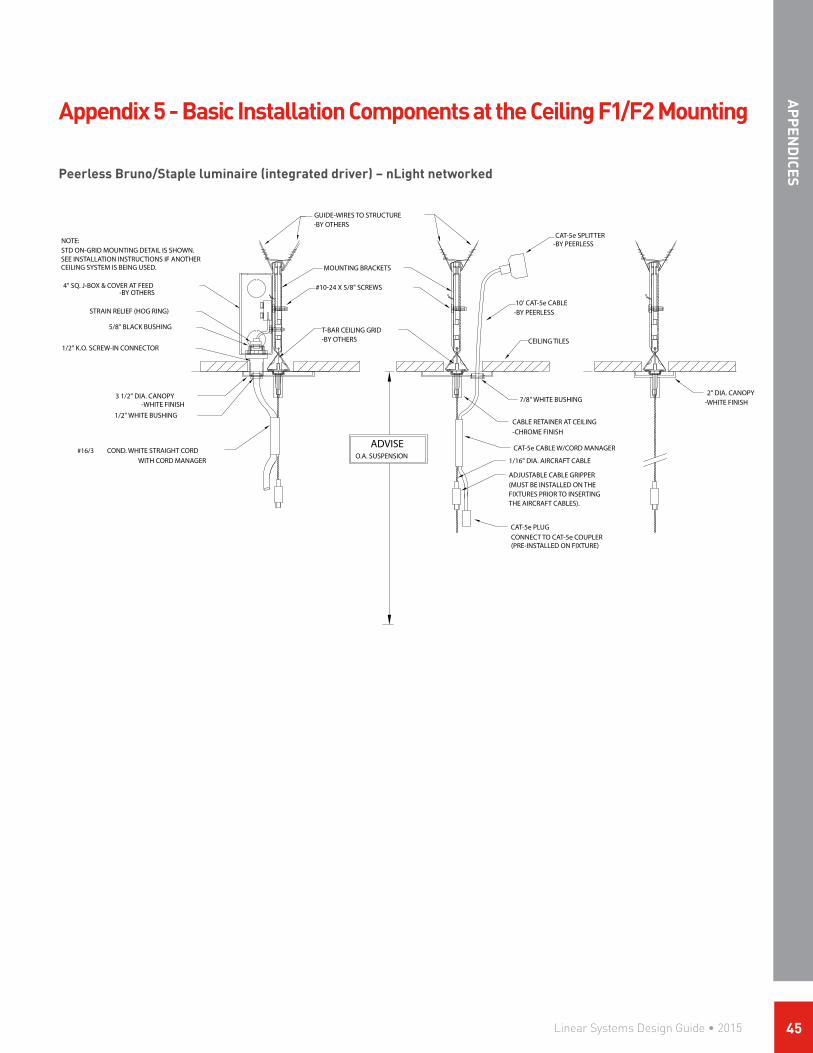
STD ON-GRID MOUNTING DETAIL IS SHOWN.SEE INSTALLATION INSTRUCTIONS IF ANOTHERCEILING SYSTEM IS BEING USED.
1/2" K.O. SCREW-IN CONNECTOR
STRAIN RELIEF (HOG RING)
5/8" BLACK BUSHING
1/2" WHITE BUSHING
4" SQ. J-BOX & COVER AT FEED -BY OTHERS
O.A. SUSPENSION
GUIDE-WIRES TO STRUCTURE-BY OTHERS
#10-24 X 5/8" SCREWS
-BY OTHERST-BAR CEILING GRID
MOUNTING BRACKETS
CEILING TILES
10' CAT-5e CABLE
CAT-5e PLUG
7/8" WHITE BUSHING
CAT-5e SPLITTER-BY PEERLESS
-BY PEERLESS
CONNECT TO CAT-5e COUPLER(PRE-INSTALLED ON FIXTURE)
NOTE:
COND. WHITE STRAIGHT CORD#16/3
3 1/2" DIA. CANOPY-WHITE FINISH
ADVISE
CABLE RETAINER AT CEILING-CHROME FINISH
-WHITE FINISH
CAT-5e CABLE W/CORD MANAGER
ADJUSTABLE CABLE GRIPPER
THE AIRCRAFT CABLES).FIXTURES PRIOR TO INSERTING(MUST BE INSTALLED ON THE
1/16" DIA. AIRCRAFT CABLEWITH CORD MANAGER
2" DIA. CANOPY
Appendix 5 - Basic Installation Components at the Ceiling F1/F2 Mounting
Peerless Bruno/Staple luminaire (integrated driver) – nLight networked
AP
PEN
DICES
Linear Systems Design Guide • 2015 45

Peerless Vellum/Open luminaire (remote driver) – nLight networked
1/2" K.O. SCREW-IN CONNECTOR
5/8" BLACK BUSHING
3 1/2" DIA. CANOPY-WHITE FINISH
7/8" WHITE BUSHING
2 x 4 J-BOX & COVER AT FEED
O.A. SUSPENSION
GUIDE WIRES TO STRUCTURE-BY OTHERS
#10-24 X 5/8" SCREWS
-BY OTHERST-BAR CEILING GRID
MOUNTING BRACKETS
3 1/2" DIA. CANOPY
CEILING TILES
10' CAT-5e CABLE
BUSHING
CAT-5e SPLITTER-BY PEERLESS
-BY PEERLESS
CAT-5e CABLEW/RJ45 PLUG
7/8" WHITE
FLEX CONDUIT W/FITTING
LOW VOLTAGE QUICK CONNECT
CABLE RETAINER AT CEILING
LOW VOLTAGE WHITE CORD
24"
-CHROME FINISH
-WHITE FINISH
WITH CORD MANAGER
1/16" DIA. AIRCRAFT CABLE
CABLE GRIPPER
THE AIRCRAFT CABLES).FIXTURES PRIOR TO INSERTING(MUST BE INSTALLED ON THE(LIMITED ADJUSTABILITY)
-BY PEERLESS
-BY PEERLESS
ACCESS PLATE FOR LINEVOLTAGE POWER TYPICAL
LOW VOLTAGE CORDFOR LED BOARDS
RECESSED MOUNT DRIVERBOX - BY PEERLESS
FLEX CONDUIT - BY PEERLESS
nLIGHT CONTROLLER(1) PER DRIVER BOX
CAT-5e CABLE TO OTHER nLIGHT DEVICE OR NETWORK BY OTHERS
CAT-5e CABLE TO OTHER nLIGHT DEVICE OR NETWORK BY OTHERS
CAT-5e CABLE WITH SPLITTER FOR SENSOR- BY PEERLESS
Appendix 5 - Basic Installation Components at the Ceiling F1/F2 Mounting
AP
PEN
DIC
ES
1/2" K.O. SCREW-IN CONNECTOR
5/8" BLACK BUSHING
3 1/2" DIA. CANOPY-WHITE FINISH
7/8" WHITE BUSHING
2 x 4 J-BOX & COVER AT FEED
O.A. SUSPENSION
GUIDE WIRES TO STRUCTURE-BY OTHERS
#10-24 X 5/8" SCREWS
-BY OTHERST-BAR CEILING GRID
MOUNTING BRACKETS
3 1/2" DIA. CANOPY
CEILING TILES
10' CAT-5e CABLE
BUSHING
CAT-5e SPLITTER-BY PEERLESS
-BY PEERLESS
CAT-5e CABLEW/RJ45 PLUG
7/8" WHITE
FLEX CONDUIT W/FITTING
LOW VOLTAGE QUICK CONNECT
CABLE RETAINER AT CEILING
LOW VOLTAGE WHITE CORD
24"
-CHROME FINISH
-WHITE FINISH
WITH CORD MANAGER
1/16" DIA. AIRCRAFT CABLE
CABLE GRIPPER
THE AIRCRAFT CABLES).FIXTURES PRIOR TO INSERTING(MUST BE INSTALLED ON THE(LIMITED ADJUSTABILITY)
-BY PEERLESS
-BY PEERLESS
ACCESS PLATE FOR LINEVOLTAGE POWER TYPICAL
LOW VOLTAGE CORDFOR LED BOARDS
RECESSED MOUNT DRIVERBOX - BY PEERLESS
FLEX CONDUIT - BY PEERLESS
nLIGHT CONTROLLER(1) PER DRIVER BOX
CAT-5e CABLE TO OTHER nLIGHT DEVICE OR NETWORK BY OTHERS
CAT-5e CABLE TO OTHER nLIGHT DEVICE OR NETWORK BY OTHERS
CAT-5e CABLE WITH SPLITTER FOR SENSOR- BY PEERLESS
Linear Systems Design Guide • 201546

Appendix 6 - Integration into an nLight building system
Connecting to the larger nLight systemWhen nLight sensors, WallPods or embedded controllers/power packs are connected in any order via CAT-5e cabling, an nLight zone is created. A networked nLight enabled fixture communicates with up to 128 other networked devices in an nLight zone. The zone can be linked to a Gateway, either directly or via Bridges, and becomes capable of remote status monitoring and control via SensorView software. The nLight gateway connect up to 1500 devices. Multiple Gateways can communicate via a LAN connection.
Network configurationAn nLight network backbone consists of one or more Bridges and a Gateway (nGWY2 CTRL & nGWY2 GFX or nGWY) communicating over CAT-5e wired connections. The architecture can be topology-free, however wide branching networks are recommended over linear runs. Any one or more RJ-45 ports on a Bridge may be used to connect to other Bridge or Gateway devices.
AP
PEN
DICES
Linear Systems Design Guide • 2015 47

2246 5th Street | Berkeley, CA 94710 | 510.845.2760 | PeerlessLighting.com©2015 Acuity Brands Lighting, Inc. All rights reserved. | 12/15 | PER_1891