linear motor drive ldm - comoso › ... › downloads › schunk_comoso_om_au… ·...
TRANSCRIPT

Original assembly and operating manual
01.00/LDM/360926/en
Linear motor drive
LDM
Assembly and Operating Manual
www.comoso.com

Original assembly and operating manual
01.00/LDM/360926/en
Imprint:
Copyright:
This manual remains the copyrighted property of SCHUNK GmbH & Co. KG. It is solely supplied
to our customers and operators of our products and forms part of the module. This
documentation may not be duplicated or made accessible to third parties, in particular
competitive companies, without our prior permission.
Technical changes:
We reserve the right to make alterations for the purpose of technical improvement.
Document number: 360926
Edition: 01.00 / 23.01.2012 / en
© SCHUNK GmbH & Co. KG, Lauffen/Neckar
All rights reserved
Impressum:
Urheberrecht:
Die vorliegende Anleitung bleibt urheberrechtlich Eigentum der SCHUNK GmbH & Co. KG. Sie
wird nur unseren Kunden und den Betreibern unserer Produkte mitgeliefert und ist Bestandteil
des Moduls. Ohne unsere ausdrückliche Genehmigung dürfen diese Unterlagen weder
vervielfältigt noch dritten Personen, insbesondere Wettbewerbsfirmen, zugänglich gemacht
werden.
Technische Änderungen:
Änderungen im Sinne technischer Verbesserungen sind uns vorbehalten.
Dokumentennummer: 360926
Auflage: 01.00 / 23.12.2011 / en
© SCHUNK GmbH & Co. KG, Lauffen/Neckar
Alle Rechte vorbehalten
Dear customer,
Congratulations on choosing a SCHUNK product. By choosing SCHUNK, you have opted for the
highest precision, premium quality and optimum service.
You are going to increase the process reliability of your production and achieve best machining
results – to the customer's complete satisfaction.
SCHUNK products are inspiring.
Our detailed assembly and operation manual will support you.
Do you have further questions? You may contact us at any time - even after purchase.
Sehr geehrter Kunde,
wir gratulieren zu Ihrer Entscheidung für SCHUNK. Damit haben Sie sich für höchste Präzision,
hervorragende Qualität und besten Service entschieden.
Sie erhöhen die Prozesssicherheit in Ihrer Fertigung und erzielen beste
Bearbeitungsergebnisse – für die Zufriedenheit Ihrer Kunden.
SCHUNK-Produkte werden Sie begeistern.
Unsere ausführlichen Montage- und Betriebshinweise unterstützen Sie dabei.
Sie haben Fragen? Wir sind auch nach Ihrem Kauf jederzeit für Sie da.
Best regards,
SCHUNK GmbH & Co. KG
Spann- und Greiftechnik
Bahnhofstr. 106 – 134
D-74348 Lauffen/Neckar, Germany
Tel. +49-7133-103-2503
Fax +49-7133-103-2189
www.de.schunk.com
Mit freundlichen Grüßen
Ihre SCHUNK GmbH & Co. KG
Spann- und Greiftechnik
Bahnhofstr. 106 – 134
D-74348 Lauffen/Neckar
Tel. +49-7133-103-2503
Fax +49-7133-103-2189
www.de.schunk.com
www.comoso.com

Table of contents
01.00/LDM/360926/en 3
Table of contents
1 About this manual ........................................................................................................ 5
1.1 Purpose/validity ....................................................................................................... 5
1.2 Target groups ........................................................................................................... 5
1.3 Symbols in this manual ............................................................................................ 5
2 Basic safety notes ......................................................................................................... 6
2.1 Appropriate use ....................................................................................................... 6
2.2 Ambient conditions and operating conditions ........................................................ 6
2.3 Product safety .......................................................................................................... 7
2.3.1 Protective equipment ................................................................................ 7
2.3.2 Constructional changes, attachments, or modifications .......................... 7
2.4 Personnel qualification ............................................................................................ 7
2.5 Safety-conscious working ........................................................................................ 8
2.6 Disposal .................................................................................................................... 8
2.7 Notes on particular risks .......................................................................................... 8
2.7.1 Protection against dangerous movements ............................................... 9
3 Warranty .................................................................................................................... 10
4 Scope of delivery ........................................................................................................ 10
5 Accessories ................................................................................................................. 11
6 Product description .................................................................................................... 12
6.1 Overview of types .................................................................................................. 12
6.2 Operation principle ................................................................................................ 15
7 Technical data ............................................................................................................ 16
8 Transport and storage ................................................................................................. 17
8.1 Transportation ....................................................................................................... 17
8.2 Storage ................................................................................................................... 17
9 Assembly .................................................................................................................... 18
9.1 Installation preparation ......................................................................................... 18
9.2 Main components .................................................................................................. 19
9.3 Assembly of the linear motor drive ....................................................................... 20
10 Electrical connection ................................................................................................... 21
10.1 Measuring system LE100 ....................................................................................... 21
10.2 Measuring system TTK 70 ...................................................................................... 22
10.3 Motor interface ..................................................................................................... 23
11 Troubleshooting ......................................................................................................... 24
www.comoso.com

About this manual
01.00/LDM/360926/en 4
11.1 Module does not move?........................................................................................ 24
12 Maintenance and repair work ..................................................................................... 25
12.1 Module description ............................................................................................... 25
12.2 Changing the motor housing ................................................................................. 26
12.3 Turn the motor plug .............................................................................................. 28
12.4 Modifying the motor plug to a different side ........................................................ 30
12.5 Motor rotation direction ....................................................................................... 32
12.6 Guided slide – Changing the support rollers on the locating bearing side ........... 33
12.7 Guided slide – Changing the support rollers on the eccentric side ........................... 34
12.8 Changing the stroke measuring system ................................................................ 36
12.8.1 Main components ................................................................................... 36
12.8.2 Changing the measuring system LE 100 .................................................. 38
12.8.3 Changing measuring system TTK 70 ........................................................ 40
12.9 Changing the magnetic strip .................................................................................. 41
12.10 Changing the wipers .............................................................................................. 43
12.11 Replacing the brake piston .................................................................................... 44
12.12 Changing limit switches and reference switches .................................................. 46
12.13 Maintenance and care ........................................................................................... 47
13 Spare parts ................................................................................................................. 48
13.1 Note regarding spare part orders .......................................................................... 48
13.2 Axes ........................................................................................................................ 49
13.3 Motors ................................................................................................................... 50
13.4 Guide...................................................................................................................... 52
13.5 Measuring system ................................................................................................. 53
13.6 Holding brake......................................................................................................... 54
13.7 Accessories ............................................................................................................ 55
14 EC-declaration of incorporation .................................................................................. 56
Applicable documents
SCHUNK Catalog Linear modules Assembly and operating manuals for sensors General terms of business
Commissioning of Indradrive (German/English) (on CD-ROM), order number 315322
The abovementioned documents can be downloaded from: www.de.schunk.com.
www.comoso.com
About this manual
01.00/LDM/360926/en 5
1 About this manual
1.1 Purpose/validity
This manual forms part of the module and describes the safe and proper use during all phases of operation.
This manual is valid only for the module specified on the front page.
1.2 Target groups
Target group Task
Manufacturer, operator Keep this manual accessible for personnel at all times.
Require personnel to read and observe this manual and the
applicable documents, especially the safety notes and
warnings.
Skilled personnel, fitters Read, observe and follow this manual and the applicable
documents, especially the safety notes and warnings.
Tab. 1
1.3 Symbols in this manual
To give you quick access to information, the following symbols will be used in this guide:
Symbol Meaning
DANGER Dangers for persons.
Non-observance causes death or serious injuries
WARNING Dangers for persons.
Non-observance can cause death or serious injuries.
CAUTION Dangers for persons.
Non-observance can cause minor injuries.
NOTICE Information about avoiding material damage.
Instruction for action, including measures in a warning or note.
1. 2.
Step-by-step instruction for action.
Observe the order.
xyz Cross reference to further information.
Tab. 2
www.comoso.com

Basic safety notes
01.00/LDM/360926/en 6
2 Basic safety notes
2.1 Appropriate use
The linear modules are exclusively designed for linear movement
of useful loads into any desired position, where the load does not
react in a manner endangering persons, property or the
environment as a result of this manipulation.
The module is intended for installation in a machine. The
requirements of the applicable guidelines must be observed and
complied with.
The module may be used only in the context of its defined
application parameters.
Any other use or use exceeding that specified is an infringement
of appropriate use. The manufacturer bears no liability for
damage resulting from such use.
2.2 Ambient conditions and operating conditions
Use the module only within its defined application
parameters ( 7 Technical data and catalog).
Make sure that the module and the top jaws are a sufficient
size for the application.
Make sure the environment is clean and the ambient
temperature corresponds to the specifications as per the
catalog. Observe the maintenance intervals ( 12.13
Maintenance and care).
Make sure that the environment is free from splash water
and vapors as well as from abrasion or processing dust. This
excludes modules that are designed specially for
contaminated environments.
www.comoso.com

Basic safety notes
01.00/LDM/360926/en 7
2.3 Product safety
The module is state of the art and complies with the recognized
safety rules at the time of delivery. However, it can present risks
if, for example:
The module is not used in accordance with its intended
purpose.
The module is not installed or maintained properly.
The EC Machine Directive, the VDE directives, the safety and
accident-prevention regulations and environmental
protection regulations valid at the usage site, or the safety
and installation notes are not observed.
2.3.1 Protective equipment
Provide protective equipment in line with EC Machinery
Directive.
2.3.2 Constructional changes, attachments, or modifications
Modifications, additions, and conversions which could impair
safety may not be made to the module without permission from
SCHUNK.
Unauthorized changes result in the exclusion from product
liability.
2.4 Personnel qualification
Assembly, initial commissioning, maintenance, and repair of the
module may be performed only by trained specialist personnel.
Every person called upon by the operator to work on the module
must have read and understood the complete assembly and
operating manual, especially the chapter 2 “Basic safety notes”.
This applies particularly to personnel only used occasionally, such
as maintenance personnel.
www.comoso.com
Basic safety notes
01.00/LDM/360926/en 8
2.5 Safety-conscious working
Avoid any manner of working that may interfere with the
function and operational safety of the module.
Observe the safety and accident prevention regulations valid
at the site of use.
2.6 Disposal
Observe the local legal provisions when disposing of the module.
2.7 Notes on particular risks
Risk of injury when the machine/system moves unexpectedly
Do not move parts by hand when the energy supply is
connected.
Do not reach into the open mechanism or the movement
area of the module.
Remove the energy supplies before installation, modification,
maintenance, or adjustment work.
Perform maintenance, modifications, and additions outside
the danger zone.
For all work, secure the module against accidental operation.
Danger of crushing and clamping between the slides and base
body during motion of the linear axis slides.
The danger zone must be surrounded by a protective barrier
during operation.
Risk of injury when the machine/system moves unexpectedly in
the case of a loss of power supply or control system
malfunction.
Use of a holding brake on the linear axis.
www.comoso.com

Basic safety notes
01.00/LDM/360926/en 9
2.7.1 Protection against dangerous movements
As a general rule, the linear motor drives may only be operated with additional safety devices that are not included in the scope of delivery.
Dangerous movements can also occur when a drive is not connected.
For this reason, always secure parts (e.g. slides) against movement.
Dangerous movements can result when errors occur in controlling the drives. The drive components are monitored in a way that malfunctions can be largely excluded when the system is correctly operated.
However, for reasons of personal safety, risk of injury and risk of property damage, you should not rely on this fact alone. Until the integrated safety features become effective, inaccurate drive movements must be expected.
Possible causes for control errors:
Incorrect cabling or wiring
Defective components
Software errors
Operating errors
Removal of safety devices
Sensor and signal transmitter errors
Entry of incorrect parameters prior to start-up
Basic physical parameters must be set before start-up. Maximum values and minimum values must be set to sensible limits. These include especially the following: stroke, speed, acceleration, torque, current, measuring system resolution, correct operating mode, hardware and software end positions, drag error, temperature monitoring etc.
Actual values during first motion at minimum speed and acceleration.
Protective equipment must be active.
Locking out of impermissible opposing motions.
www.comoso.com

Warranty
01.00/LDM/360926/en 10
3 Warranty
The warranty is valid for 24 months from the date of delivery to
the production facility under the following conditions:
Intended use in 1-shift operation
Observance of the maintenance and lubrication intervals
( 12.13 Maintenance and care)
Observance of the ambient conditions and operating
conditions ( 2.2 Ambient conditions and operating
conditions)
Parts touching the workpiece and wearing parts are not part of
the warranty. Also observe our general terms of business.
WARNING
Malfunctions caused by defective components may only be
corrected by the replacement of these components.
Defective components may only be replaced with SCHUNK
original spare parts
4 Scope of delivery
The scope of delivery comprises:
Linear motor drive type LDM, in the ordered variant
Start-up DVD
Operating manual
www.comoso.com
Accessories
01.00/LDM/360926/en 11
5 Accessories
The following accessories are available for the module:
Centering sleeves For precisely fitting connections between axes and adapter
plates Inductive sensors
For end position control and reference measurement
Mechanical limit switches
For end position control
Connection cable for reference
and limit switches
All required connection cables
Shock absorber
For supporting the masses in case of system failures
Wipers
For wiping the tracks during operation
Cable tracks
Safe energy supply with moving actuators
Holding brake Pneumatic standstill brake for controller relief and for
vertical applications
Pneumatic switching valve
For controlling the holding brake
Cable sets Various cable sets and cable lengths for different controller
types and distances
Commissioning tools Start-up software, programming cable and commissioning
instructions for controllers
Drive controllers and control
units
Proven and approved components for your application
scenario
Tab. 3
Order accessories separately.
For additional accessories catalog.
www.comoso.com

Product description
01.00/LDM/360926/en 12
6 Product description
6.1 Overview of types
LDM – ES - 0100 - 1 – 345 - 640 - LxBV–111A - 0122
Fig. 1: Linear motor drive
Specify the material number and serial number in all inquiries
and spare part orders.
Example
V = brake valve B = brake x = placeholder L/R = Motor left/right
Stroke measuring system
Limit and reference switches
Axis length
Useful stroke
number of active slides
Size
S = Standard slide L = Longitudinal slides G = Extra longitudinal slides
U = supported E = single motor D = double motor
Profil type
Linear motor drive
www.comoso.com

Product description
01.00/LDM/360926/en 13
Fig. 2:
*= Recommended products
LDM-ES-0100, LDM-ES-0200 * LDM-US-0200 *
LDM-EL-0200, LDM-EL-0400 * LDM-UL-0400 *
www.comoso.com

Product description
01.00/LDM/360926/en 14
LDM-US-0100-2 (2. Slides active)
LDM-US-0100-2 (2. Slides passive)
Fig. 3: Linear motor drive type LDM with two Slides
All versions of the linear motor drives of type LDM are available
with multiple slides.
www.comoso.com

Product description
01.00/LDM/360926/en 15
6.2 Operation principle
The linear motor drive type LDM is a directly driven drive module
for linear movements. The driving force is transmitted directly to
the slide without any mechanical transmission elements. The axis
is especially suited for applications for which very high dynamics
are required.
The overall concept of the linear motor drive is characterized by
its extremely compact design. Thanks to the good guidance of
the slide and the light-weight design of the axis, the drive reaches
very high speeds, accelerations and repeat accuracies.
Fig. 4: Functional principle of the linear motor drive type LDM
1 Copper coil 2 Directions of movement
3 Primary part 4 Permanent magnets
5 Iron mount 6 Secondary part
Tab. 4
You can manipulate the driving force, acceleration and speed of
the slide by regulating the phase and the amplitude of the
electrical current applied at the primary part (3).
As standard, a magnetic measuring system integrated in the axis
is used to determine the current position of the drive.
Optical or absolute stroke measuring systems are available as
options.
www.comoso.com

Technical data
01.00/LDM/360926/en 16
7 Technical data
You can view additional technical data in our catalog. The respective latest version is valid.
Motor size LDM-ES-0100 LDM-ES-0200*3 LDM-EL-0200 LDM-EL-0400*3
Rated force *2 (N) On request 200 200 350
Maximum force *1 (N) On request 500 500 1000
Repeat accuracy (mm) On request ±0,01 ±0,01 ±0,01
Max. continuous current at
standstill
(Aeff) On request 3,8 3,9 6,8
Maximum current (Aeff) On request 10,1 15,5 25
Winding resistance at 25°C (Ohm) On request 3,1 3,9 1,6
Test voltage (V) On request 2000 2000 2000
Ambient temperature (°C) On request 10 - 40 10 - 40 10 - 40
Max. surface temperature (°C) On request 70 70 70
Motor size LDM-US-0200*3 LDM-UL-0400*3
Rated force *2 (N) 200 350 *¹) depending on control type
*²) depending on the installation situation
(heat dissipation)
*³) Recommended
product
Maximum force *1 (N) 500 1000
Repeat accuracy (mm) ±0,01 ±0,01
Max. continuous current at
standstill
(Aeff) 3,8 6,8
Maximum current (Aeff) 10,1 25
Winding resistance at 25°C (Ohm) 3,1 1,6
Test voltage (V) 2000 2000
Ambient temperature (°C) 10 - 40 10 - 40
Max. surface temperature (°C) 70 70
Tab. 5: Technical data of the linear motor drive
www.comoso.com

Transport and storage
01.00/LDM/360926/en 17
8 Transport and storage
8.1 Transportation
The linear motor drives of type LDM are precision drives. The
packaging must protect the drive from all external effects (e.g.
mechanical shocks and humidity).
8.2 Storage
Store the product in a clean, dry environment. Ambient
temperature 15 - 40°C.
No condensation permitted!
www.comoso.com

Assembly
01.00/LDM/360926/en 18
9 Assembly
9.1 Installation preparation
DANGER
Danger to life due to strong magnetic fields even in a shut-
down state.
The secondary parts integrated in the linear motor drive type
LDM are high-performance permanent magnets. Medical
devices, e.g. pacemakers or hearing aids, can be destroyed or
can cause malfunctions.
Observe an adequate minimum distance to the secondary
part if you have a pacemaker or use a hearing aid or other
devices.
DANGER
Danger to life due to electric shock.
Touching live parts can be deadly.
Work on electrical installations or equipment may only be
carried out by electricians according to electrical standards.
Fig. 5: Magnetic surface of linear motor drive type LDM
www.comoso.com
Assembly
01.00/LDM/360926/en 19
Note
During installation and start-up, observe the technical data.
The linear motor drive catalog contains technical data on
Linear motor drive type LDM
Limit switches
Reference switch
Direct stroke measuring system
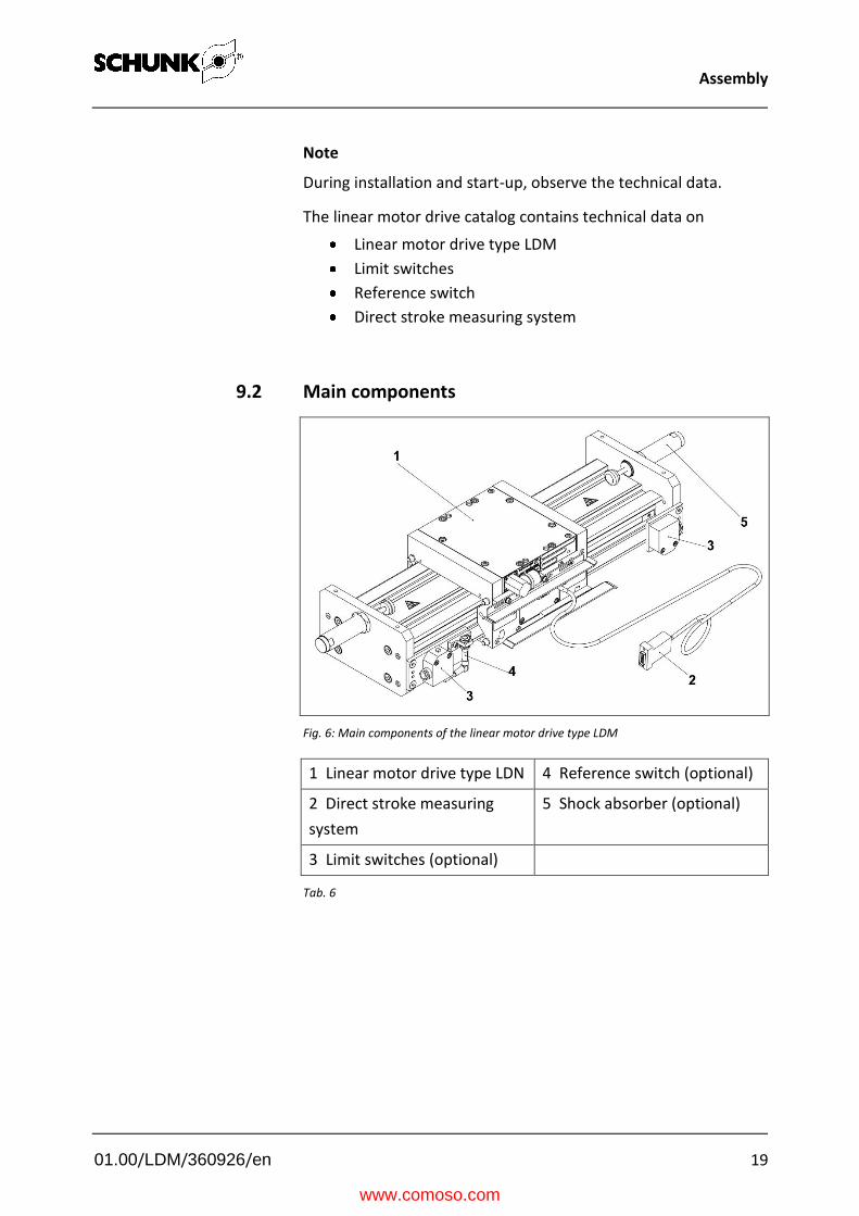
9.2 Main components
Fig. 6: Main components of the linear motor drive type LDM
1 Linear motor drive type LDN 4 Reference switch (optional)
2 Direct stroke measuring
system
5 Shock absorber (optional)
3 Limit switches (optional)
Tab. 6
www.comoso.com

Assembly
01.00/LDM/360926/en 20
9.3 Assembly of the linear motor drive
WARNING
Danger of crushing due to uncontrolled movements.
Only carry out work on the linear motor drive while the
machine is shut off.
Make sure that neither electric nor pneumatic energy is
present at the linear motor drive.
Fig. 7: Assembly surfaces of the linear motor drive type LDM
1 Adapter plate 2 Centering sleeve 3 Cylindrical screws
Tab. 7
The linear motor drives have multiple mounting surfaces for
additional linear axes. These are assembled using adapter plates.
www.comoso.com
Electrical connection
01.00/LDM/360926/en 21
10 Electrical connection
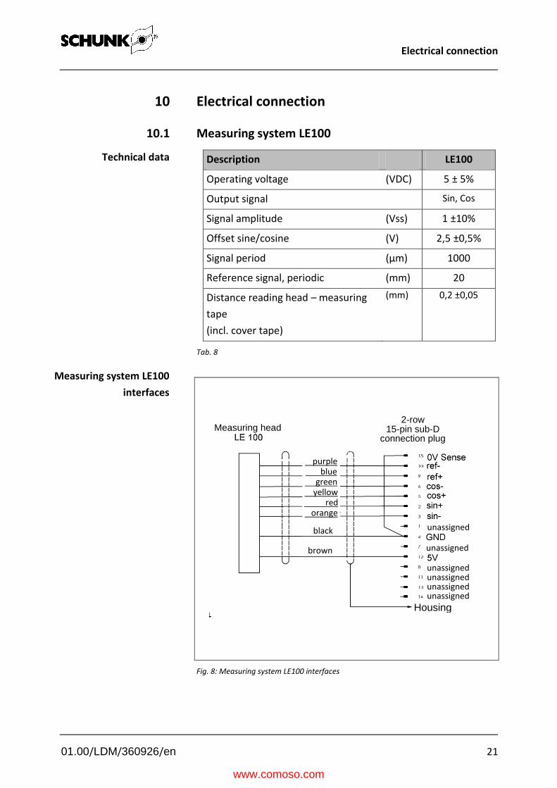
10.1 Measuring system LE100
Description LE100
Operating voltage (VDC) 5 ± 5%
Output signal Sin, Cos
Signal amplitude (Vss) 1 ±10%
Offset sine/cosine (V) 2,5 ±0,5%
Signal period (µm) 1000
Reference signal, periodic (mm) 20
Distance reading head – measuring
tape
(incl. cover tape)
(mm) 0,2 ±0,05
Tab. 8
Fig. 8: Measuring system LE100 interfaces
Technical data
Measuring system LE100
interfaces
2-row 15-pin sub-D
connection plug Measuring head
purple blue green yellow red orange
black
brown
unassigned
unassigned
unassigned unassigned unassigned unassigned
Housing
www.comoso.com

Electrical connection
01.00/LDM/360926/en 22
10.2 Measuring system TTK 70
Description TTK 70
Operating voltage (VDC) 7-12V
Output signal Sin, Cos
Signal amplitude Hiperface
Offset sine/cosine (Vss) 1 ±10%
Signal period (V) 2,5 ±0,5%
Reference signal, periodic (µm) 1000
Distance reading head – measuring
tape
(incl. cover tape)
(mm) 0,2 ±0,05
Tab. 9
Fig. 9: Measuring system cable TTK 70 interfaces
Technical data
Measuring
system cable TTK 70
interfaces
Housing
8-pin circular plug
2-row 15-pin sub-D connection
plug
brown
white
black
pink
yellow or grey
purple or green
blue
red
red
pink
black
blue
white
brown
yellow or grey
purple or green
www.comoso.com

Electrical connection
01.00/LDM/360926/en 23
10.3 Motor interface
Fig. 10: Power connector
Fig. 11:Motor interfaces
View type 1 and type 3
Plug
Ground
black yellow / green blue red
yellow
red
www.comoso.com

Troubleshooting
01.00/LDM/360926/en 24
11 Troubleshooting
11.1 Module does not move?
Possible cause Remedial measures
Carriage jammed Check distance between the secondary part and the engine, if there are metal parts on the magnet For modules with brakes - Check compressed air supply
Eend switch and reference switch without function, faulty or incorrect setting
Repair proximity switch
Switch was away adjusts
documentation chapter 12.12
A component is broken, e.g. through
overloading
Replace component or send the module with a
repair order to SCHUNK.
Make sure that the module was only used in the
context of its defined application parameters
7 Technical data or catalog.
If necessary check the application with the
calculation program for gripping modules (SSG).
Error in the cabelingt Check connection of power cables and encoder
cables
Control error Check error display of the controller
call hotline +49-7133-2333
Tab. 10
www.comoso.com
Maintenance and repair work
01.00/LDM/360926/en 25
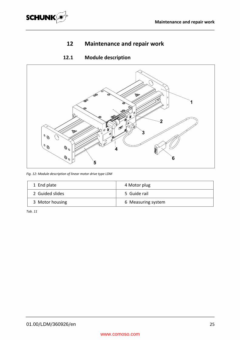
12 Maintenance and repair work
12.1 Module description
Fig. 12: Module description of linear motor drive type LDM
1 End plate 4 Motor plug
2 Guided slides 5 Guide rail
3 Motor housing 6 Measuring system
Tab. 11
www.comoso.com

Maintenance and repair work
01.00/LDM/360926/en 26
12.2 Changing the motor housing
WARNING
During installation and commissioning, observe the technical
data.
As a general rule, all work on the drives and control units
may be performed only while they are shut down. There
must not be any electrical signals present.
Allow the linear motor to cool down before starting any
assembly or disassembly work.
Fig. 13: Changing the motor housing of a linear motor drive type LDM
1. Remove protective conductor.
2. Remove the screws (1).
3. Using lifting screws M6x35 ISO 4762 (2), lift the motor
housing to bridge the magnetic force.
4. Completely remove the motor housing (3).
Uninstalling the motor
housing
www.comoso.com

Maintenance and repair work
01.00/LDM/360926/en 27
WARNING
Danger of crushing!
Never install the motor without lifting screws
1. Mount the lifting screws (2). (leave 5 mm protruding)
2. Place the motor housing (3) on the guide rail.
3. Slowly unscrew the lifting screws (2) one by one and set the
motor housing onto the guided slide (4).
4. Fit the 8 screws (1).
5. Connect the protective conductor
Installing the motor
housing
www.comoso.com
Maintenance and repair work
01.00/LDM/360926/en 28
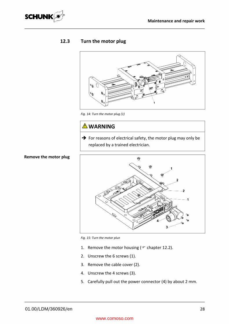
12.3 Turn the motor plug
Fig. 14: Turn the motor plug (1)
WARNING
For reasons of electrical safety, the motor plug may only be
replaced by a trained electrician.
Fig. 15: Turn the motor plun
1. Remove the motor housing ( chapter 12.2).
2. Unscrew the 6 screws (1).
3. Remove the cable cover (2).
4. Unscrew the 4 screws (3).
5. Carefully pull out the power connector (4) by about 2 mm.
Remove the motor plug
www.comoso.com
Maintenance and repair work
01.00/LDM/360926/en 29
Carefully turn the power connector into the new position.
NOTICE
Be careful with the cable when mounting the power
connector. The cable must not be damaged or subjected to
mechanical loads.
The cable must not be crushed when mounting the cable
cover.
Observe the correct motor rotation direction.
1. Carefully press the power connector (4) into the notch
2. Screw in the 4 screws (3).
3. Lay the cable parallel into the slot
4. Fit the the cable cover (2).
5. Screw in the 6 screws (1).
6. Install the motor housing ( chapter 12.2).
Fit the motor plug
www.comoso.com
Maintenance and repair work
01.00/LDM/360926/en 30
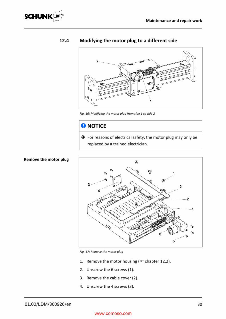
12.4 Modifying the motor plug to a different side
Fig. 16: Modifying the motor plug from side 1 to side 2
NOTICE
For reasons of electrical safety, the motor plug may only be
replaced by a trained electrician.
Fig. 17: Remove the motor plug
1. Remove the motor housing ( chapter 12.2).
2. Unscrew the 6 screws (1).
3. Remove the cable cover (2).
4. Unscrew the 4 screws (3).
Remove the motor plug
www.comoso.com

Maintenance and repair work
01.00/LDM/360926/en 31
5. Remove the cover (4).
6. Carefully pull out the power connector (6) by about 2 mm.
Carefully turn the power connector into the new position.
NOTICE
Be careful with the cable when mounting the power
connector. The cable must not be damaged or subjected to
mechanical loads.
The cable must not be crushed when mounting the cable
cover.
Observe the correct motor rotation direction.
1. Carefully press the power connector (6) into the notch on the
opposing side.
2. Screw in the 4 screws (5) to fasten the power connector.
3. Lay the cable parallel into the slot.
4. Fit the cover (4) on the opposing side.
5. Screw in the 4 screws (3).
6. Fit the the cable cover (2).
7. Screw in the 6 screws (1).
8. Install the motor housing ( chapter 12.2).
Fit the motor plug
www.comoso.com

Maintenance and repair work
01.00/LDM/360926/en 32
12.5 Motor rotation direction
Fig. 18 Motor rotation direction for right motor
1 Motor rotation direction arrow
2 Measuring system direction arrow
Tab. 12
Abb. 19: Motor rotation direction for left motor
1 Motor rotation direction arrow
2 Measuring system direction arrow
Tab. 13
NOTICE
When mounting the motor take care to ensure that the
arrow on the motor (1) points in the same direction as the
arrow on the measuring system cover (2).
DANGER
If the arrows point in opposite directions the linear motor drive will either not function or uncontrolled movements may occur.
www.comoso.com

Maintenance and repair work
01.00/LDM/360926/en 33
12.6 Guided slide – Changing the support rollers on
the locating bearing side
Fig. 20: Support roller change on locating bearing side
1. Remove the roller cover (1).
2. Pull out the 4 support roller bearings (2) using the extracting
tool (3).
3. Remove the 4 support rollers (4).
1. Fit the 4 support rollers (4).
2. Fit the 4 support roller bearings (2).
3. Adjust the guided slide using the eccentric shafts
( chapter 12.7)
4. Check the initial tension ( 12.7 “Checking the initial
tension”).
5. Fit the roller cover (1).
Uninstalling the support
rollers
Installing the support
rollers
www.comoso.com

Maintenance and repair work
01.00/LDM/360926/en 34
12.7 Guided slide – Changing the support rollers on the eccentric
side
Fig. 21: Support roller change on eccentric side
1. Remove the 2 roller covers (1).
2. Unscrew the 8 pressure pins (2).
3. Pull out the 4 eccentric shafts (3) using the extracting tool (4).
4. Remove the 4 support rollers (5).
1. Fit the 5 support rollers (4).
2. With a rotary motion, fit the 4 eccentric shafts (3) into place.
3. Turn the eccentric shaft (3) using a hexagon socket wrench
until you can no longer turn the support roller (5) by hand.
4. Check the initial tension ( 12.7 “Checking the initial
tension”).
5. Screw in the 8 new pressure pins (2) – tightening torque of 2
Nm.
6. Fit the 2 roller covers (1).
Uninstalling the support
rollers
Installing the support
rollers
www.comoso.com

Maintenance and repair work
01.00/LDM/360926/en 35
Fig. 22: Track width
1. Apply marking paste to all guideways
2. Move the guided slides.
Check the running track width – track width B = 4 – 5 mm
Check the initial tension
www.comoso.com

Maintenance and repair work
01.00/LDM/360926/en 36
12.8 Changing the stroke measuring system
NOTICE
Due to the adjustment work required, the stroke measuring
system should only be changed by specialist personnel.
12.8.1 Main components
Different measuring systems are used in the drives. These
operating instructions describe two measuring systems.
LE 100
TTK70
For more information on the optical stroke measuring systems,
refer to the separate operating manuals.
The measuring system LE 100 is a non-contact incremental
measuring system. In conjunction with the measuring tape in the
Schunk axes, the sensor head supplies a sin - cos signal and a
periodically recurring reference signal.
Fig. 23: Measuring system modules
1 Reading head LE 100 4 Distance between
between reading head and
covering tape 2 Magnetic strip LE 100
3 Marking on magnetic strip 5 Cover tape
Tab. 14
Measuring system LE 100
www.comoso.com

Maintenance and repair work
01.00/LDM/360926/en 37
The measuring system TTK 70 is a non-contact absolute
measuring system. In conjunction with the measuring tape in the
Schunk axes, the sensor head supplies a periodically recurring
signal (1 Vss) and Hiperface information.
Fig. 24: Measuring system modules
1 Reading head TTK 70 4 Distance between between
reading head and covering tape 2 Magnetic strip TTK 70
3 Marking on magnetic strip 5 Cover tape
Tab. 15
Measuring system
TTK 70
www.comoso.com
Maintenance and repair work
01.00/LDM/360926/en 38
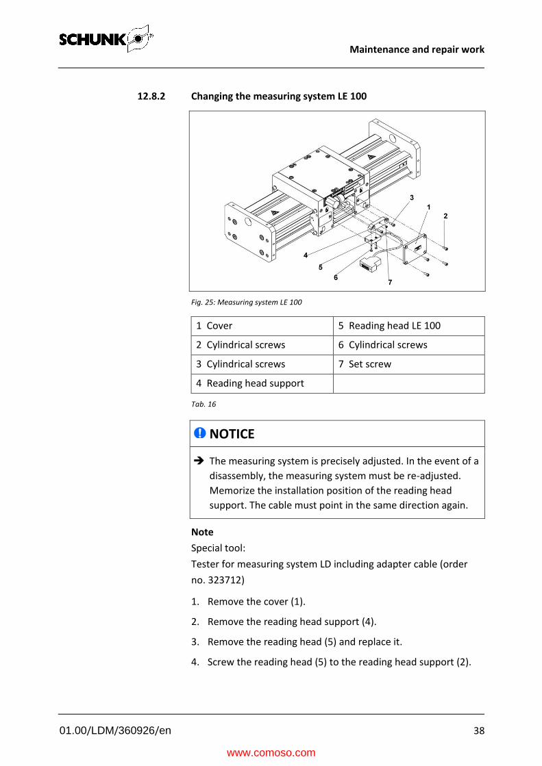
12.8.2 Changing the measuring system LE 100
Fig. 25: Measuring system LE 100
1 Cover 5 Reading head LE 100
2 Cylindrical screws 6 Cylindrical screws
3 Cylindrical screws 7 Set screw
4 Reading head support
Tab. 16
NOTICE
The measuring system is precisely adjusted. In the event of a
disassembly, the measuring system must be re-adjusted.
Memorize the installation position of the reading head
support. The cable must point in the same direction again.
Note
Special tool:
Tester for measuring system LD including adapter cable (order
no. 323712)
1. Remove the cover (1).
2. Remove the reading head support (4).
3. Remove the reading head (5) and replace it.
4. Screw the reading head (5) to the reading head support (2).
www.comoso.com

Maintenance and repair work
01.00/LDM/360926/en 39
5. Screw the reading head support (4) into the recess on the
slide. Ensure parallel position.
6. The set and mounting screws on the reading head support
with reading head have the following meaning:
7. Use the measuring system tester to test the electric output
signal of the reading head.
8. Based on the result, you can calculate the distance between
the ruler and the reading head. It must be 0.2 ±0.05 mm along
the entire length.
9. If necessary, use the set screw (7) to adjust the height.
10. When the height is adjusted correctly, set the height
adjustment using the screws (3).
NOTICE
When installing the reading head support complete with
reading head, ensure the correct installation position. The
markings on the reading head (1) and the ruler (2) must be
on the same side.
Fig. 26: Markings on reading head and ruler LE 100
NOTICE
Because Schunk offers other stroke measuring systems in
addition to the stroke measuring system described here, you
must also observe the corresponding separate
documentation.
www.comoso.com

Maintenance and repair work
01.00/LDM/360926/en 40
12.8.3 Changing measuring system TTK 70
Fig. 27: Measuring system TTK 70
1 Installation set for measuring
system TTK70
2 Connection cable
Tab. 17
NOTICE
The measuring system may only be replaced by authorized
service staff.
www.comoso.com

Maintenance and repair work
01.00/LDM/360926/en 41
12.9 Changing the magnetic strip
Fig. 28: Changing the ruler
1 Guided slides 4 Guide rail
2 Magnetic strip clamp 5 Protective film
3 Magnetic strip 6 Cover tape
Tab. 18
NOTICE
The magnetic strip of the measuring system must not be
exposed to a strong magnetic field. At about 30 gauss or
more, the magnetic strip encoding will be destroyed. Keep it
away from the secondary part (permanent magnets) of the
linear motor drive.
NOTICE
Pay attention to the marking on the magnetic strip. (see the
documentation on changing the measuring system)
1. Move the guided slide (1) to one side.
2. Unscrew the 2 magnetic strip clamps (2).
3. Carefully detach the magnetic strip (3 and 6) from the guide
rail (4) using a knife point and pull it off.
www.comoso.com

Maintenance and repair work
01.00/LDM/360926/en 42
4. Carefully clean the guide rail (4) of all adhesive residue using
petroleum ether.
5. Slide the magnetic strip (3) underneath the guided slide (1)
and place it on the guide rail (4).
6. Length of the magnetic strip (3) = length of the guide rail (4) -
38 mm.
7. Slightly lift up one side of the magnetic strip (3) and use
forceps to remove the protective film (5) from the adhesive
film.
8. Press the magnetic strip (3) onto the guide rail (4) while pulling
off the protective film.
9. When you are half-way done, slide the guided slide (1) to the
opposite side.
10. Slide the covering tape (6) underneath the guided slide (1)
and place it on the magnetic strip (4).
11. Slightly lift up one side of the covering tape (6) and use
forceps to remove the protective film (5) from the adhesive
film.
12. Press the covering tape (6) onto the magnetic strip (3) while
pulling off the protective film.
13. Unscrew the 2 magnetic strip clamps (2).
www.comoso.com

Maintenance and repair work
01.00/LDM/360926/en 43
12.10 Changing the wipers
NOTICE
When using wipers, it is especially important that you clean
the guide strips and lubricate them with an oil-soaked cloth.
Note that the usable stroke is reduced when installing
wipers.
Fig. 29: Changing the wipers
1 Guided slides 2 Mounting screw 3 Wipers
Tab. 19
1. Slide the guided slide (1) to the center of the axis.
2. Release the mounting screw (2).
3. Change the wiper (3).
4. Tighten the mounting screw (2).
www.comoso.com

Maintenance and repair work
01.00/LDM/360926/en 44
12.11 Replacing the brake piston
The pneumatic holding brake is not a safety component.
The pneumatic holding brake prevents the guide rail from moving
with respect to the guided slides when a force less than 150 N
per brake is applied to the guide (braking effect when new).
The slide or guide rail may not be moved when the brakes are
applied. This can damage the linear motor drive. This especially
reduces the braking effect.
The braking effect is also influenced by worn or dirty braking
surfaces. Observe the braking effectiveness and consult our
service department when the brakes become less effective.
In normal operation the braking effect is released by compressed
air and a spring assembly applies the brake when required. Note
that the braking effect is immediately released when the
compressed air supply is switched on and this can lead to
dangerous movements.
The brake releases when compressed air at a minimum pressure
of 4 bar (maximum 8 bar) is present at the connection of the
linear motor drive.
Integrate the holding brake into the control concept for your
system in a sensible manner. Note that this is a stationary
holding brake and is not suitable for continuous operation.
WARNING
Switch off the control system and compressed air
The brake piston is pre-tensioned with disk springs.
Notes
www.comoso.com

Maintenance and repair work
01.00/LDM/360926/en 45
Fig. 30: Replacing the brake piston
1 Brake cover 2 Retaining ring 3 O-Ring
4 Disk spring 5 Brake piston
Tab. 20
1. Using a vise, clamp the brake cover (1).
2. Remove the retaining ring (2).
3. Slowly loosen the vise.
4. Remove the brake cover (1), O-ring (3) and disk springs (4).
5. Using pliers (with braces), pull out the brake piston (5).
1. Slightly grease and insert the O-ring (3).
2. Insert the brake piston (5) and fit the membrane into place.
3. Fit the disk springs (4) and the brake cover (1).
NOTICE
When installing the disk springs (4), make sure the individual
disk springs are placed in the correct position.
4. Set the vise onto the brake cover (1) and press in the cover.
5. Fit the retaining ring (2)
6. Loosen and remove the vise.
Uninstalling the brake
piston
Installing the brake
piston
www.comoso.com

Maintenance and repair work
01.00/LDM/360926/en 46
12.12 Changing limit switches and reference switches
Fig. 31: Mechanical limit switches and inductive reference switch
1. Limit switches, mechanical 5. Limit switch baseplate
2. Reference switch, inductive 6. Distance plate
3. Switching lug 7. Switching distance,
mechanical limit switch
4. Limit and reference switch
baseplate
8. Switching distance,
inductive reference switch
Tab. 21
1. Unscrew the mounting screws of the switch baseplate (4/5).
2. Unscrew the mounting screws of the switch (1/2) and remove
the switch.
3. Install the new switch and adjust the switching distance (7/8).
4. Fit the switch (1/2) and baseplate (4/5)
5. Perform a test run.
www.comoso.com

Maintenance and repair work
01.00/LDM/360926/en 47
12.13 Maintenance and care
WARNING
Only carry out work on linear motor drives
while the machine is switched off.
Fig. 32: Maintenance of guide and secondary part
To ensure the operational safety of the linear motor drive type
LDN over a long period of time, the operating personnel must
carry out maintenance work in specific intervals.
Rub the guide strips (1) with an oil-soaked cloth.
Clean the secondary part (2) with ethyl alcohol.
Weekly maintenance
(depending on degree of
contamination)
Every 2 to 4 weeks
www.comoso.com
Spare parts
01.00/LDM/360926/en 48
13 Spare parts
13.1 Note regarding spare part orders
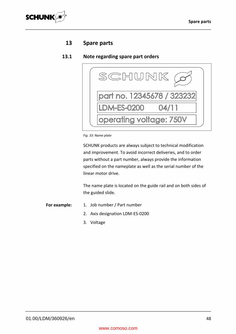
Fig. 33: Name plate
SCHUNK products are always subject to technical modification
and improvement. To avoid incorrect deliveries, and to order
parts without a part number, always provide the information
specified on the nameplate as well as the serial number of the
linear motor drive.
The name plate is located on the guide rail and on both sides of
the guided slide.
1. Job number / Part number
2. Axis designation LDM-ES-0200
3. Voltage
For example:
www.comoso.com

Spare parts
01.00/LDM/360926/en 49
13.2 Axes
Fig. 34: Spare parts – Axis
Item Type of axis Designation Number Option Order no.
11 LDM-ES(L) Profile guide 1 Secondary part 1 H 353 121
11 LDM-EL(S) Profile guide 2 Secondary part 1 H 353 123
12 LDM-US(L) Profile guide 2 Secondary part 1 H 353 125
13 All End plate 1 345 513
14 All Centering sleeve Ø 9 2 301 587
15 All Centering sleeve Ø 12 4 300 441
16 All Ethyl alcohol 50ccm 1 R 301 480
17 All Oil 50ccm 1 R 301 478
18 All Measuring system tester 1 323 712
19 All Documentation for start up of
Indradrive (German/English) including
CD-ROM
1 315 016
Tab. 22
S Only with optional switch H Stroke-dependent R Cleansing agent E End position dampening
www.comoso.com

Spare parts
01.00/LDM/360926/en 50
13.3 Motors
Fig. 35: Spare parts – Motors
Item Type of axis Designation Number Option Order no.
20 LDM-ES-0100 Linear motor MGM-ES-0100-LS 1 2 363 007
LDM-ES-0100 Linear motor MGM-ES-0100-RS 1 1 360 520
LDM-ES-0200 Linear motor MGM-ES-0200-LS 1 2 363 009
LDM-ES-0200 Linear motor MGM-ES-0200-RS 1 1 360 514
LDM-EL-0200 Linear motor MGM-EL-0200-LS 1 2 363 023
LDM-EL-0200 Linear motor MGM-EL-0200-RS 1 1 360 518
LDM-EL-0400 Linear motor MGM-EL-0400-LS 1 2 363 010
LDM-EL-0400
M(U)L
Linear motor MGM-EL-0400-RS 1 1 360508
21 All Centering sleeve Ø 9 2 352 577
Tab. 23
www.comoso.com
Spare parts
01.00/LDM/360926/en 51
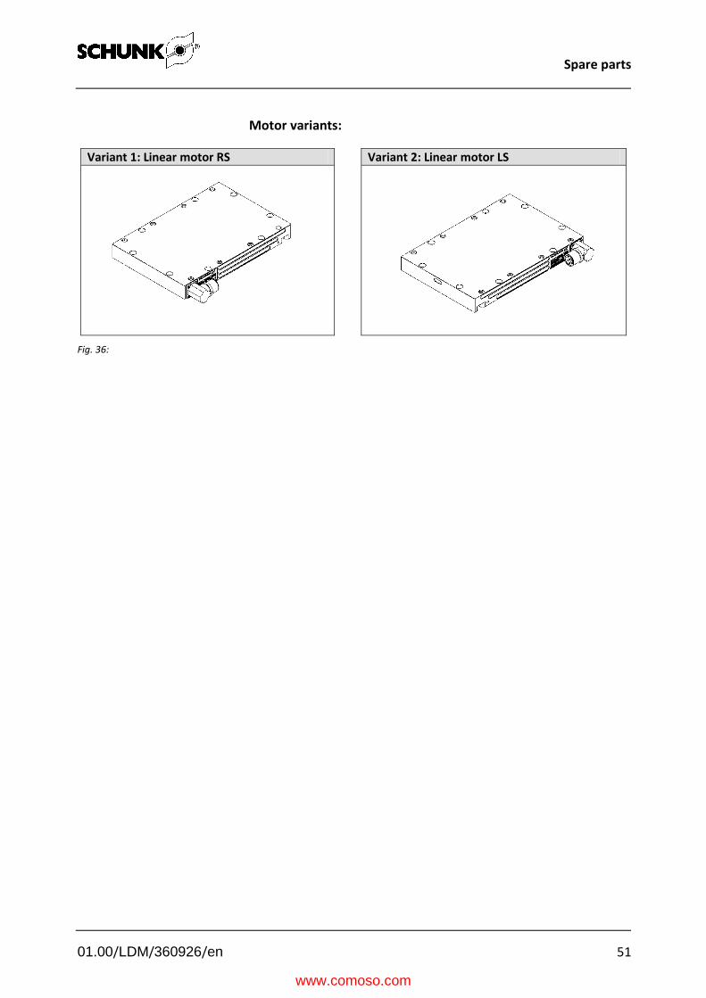
Motor variants:
Variant 1: Linear motor RS
Variant 2: Linear motor LS
Fig. 36:
www.comoso.com

Spare parts
01.00/LDM/360926/en 52
13.4 Guide
Fig. 37: Spare parts – Guide
Item Type of axis Designation Number Order no.
31a M(U) Roller cover 4 332 808
31b M(U)L Roller cover 4 341 769
32a M(U) Support roller 8 332 826
32b M(U)L Support roller 12 332 826
33a M(U) Support roller bearing 4 332 802
33b M(U)L Support roller bearing 8 332 802
34 All Eccentric shaft 4 332 801
35 All Pressure pin 8 300 176
36 All Clamping element 8 300 891
Tab. 24
www.comoso.com

Spare parts
01.00/LDM/360926/en 53
13.5 Measuring system
Fig. 38: Spare parts – Measuring system LE100
Item Type of axis Designation Number Option Order no.
41a All Reading head LE100 5 m 1 336 025
41b Reading head LE100 10 m 1 341 782
42a All Magnetic strip LE100 1 H 346 611
43 All Magnetic strip clamp 2 333 991
Tab. 25
www.comoso.com

Spare parts
01.00/LDM/360926/en 54
13.6 Holding brake
Fig. 39: Spare parts–Brake
Item Type of axis Designation Number Order no.
51a M(U) Installation set for pneumatic emergency
stop brake
1
333 645
51b M(U)L Brake valve, 10 m cable (GAS) 2 333 645
52 All Brake valve, 10 m cable (GAS) 1 337 784
Tab. 26
www.comoso.com

Spare parts
01.00/LDM/360926/en 55
13.7 Accessories
Fig. 40: Spare parts – Accessories
Item Type of axis Designation Number Order no.
61 All Mechanical limit switch 2 308 190
62 All Inductive limit switch PNP 2 312 586
63 All Inductive reference switch PNP PNP 1 306 182
64 All Inductive reference switch NPN 1 318 432
65 All Shock absorber 2 319 701
Tab. 27
www.comoso.com

EC-declaration of incorporation
01.00/LDM/360926/en 56
14 EC-declaration of incorporation
In terms of the EC Machinery Directive 2006/42/EC, annex II, part B
Manufacturer/
distributor
SCHUNK GmbH & Co. KG.
Spann- und Greiftechnik
Bahnhofstr. 106 – 134
D-74348 Lauffen/Neckar, Germany
We hereby declare that the following product:
Product designation: Linear motor drive
Type designation: LDM
meets the applicable basic requirements of the Machinery Directive (2006/42/EC).
The incomplete machine may not be put into operation until conformity of the machine into
which the incomplete machine is to be installed with the provisions of the Machinery
Directive (2006/42/EC) is confirmed.
Applied harmonized standards, especially:
EN ISO 12100-1 Safety of machines - Basic concepts, general principles for design –
Part 1: Basic terminology, methodology
EN ISO 12100-2 Safety of machines - Basic concepts, general principles for design –
Part 2: Technical principles
The manufacturer agrees to forward on demand the special technical documents for the
incomplete machine to state offices.
The special technical documents according to Appendix VII, Part B belonging to the
incomplete machine have been compiled.
Person responsible for documentation: Mr. Michael Eckert, Tel.: +49(0)7133/103-2204
Location, date/signature:
Lauffen, Germany,
January 2012 pp.
Title of the signatory Director, Development
www.comoso.com