linear guideways 5.4 type n/o - everbright.com.tw · ha350 du kzst cage: - hw 10 end pieces - gfn...
TRANSCRIPT

45
5
Type N/OThe type N/O linear guideways are equipped with needle cages and are particularly suitable for applications involving high loads. Compared with similar needle guideways, smaller displacement resistance values are recorded thanks to the use of the SCHNEEBERGER composite cage made of steel and plastic.
Benchmark dataTrack and surface quality• Finely ground supporting and/or locating surfaces and tracks (90o V-profile)
Materials (standard)• Rails from through hardened tool steel 1.2842, hardness 58 - 62 HRC.• For non-corrosive guideways tool steel 1.4034 is used.• Rolling element made of through hardened roller bearing steel, hardness 58 - 64 HRC.
Rolling element• Needle
Speed• 1 m/s• 1 m/s with cage control
Acceleration• 50 m/s2
• 200 m/s2 with cage control
Accuracy• Type N/O linear guideways are available in three quality classes (see chapter 9)
Operating temperatures• -40o C to +80o C
5.4 Type N/O
Linear guideways
5.4
Typ
e N
/O

46
5
A-A A
A
e1
q
L2 L1 L2
L
m1
u1
m
u
N
J1
F
d
N
g
B
f e
J
Dw
A+0 - 0
,3
N
O
Dimensions and load capacities of type N/O
Linear guideways Ty
pe
Size
L in
mm
Weight in g A B Dw F J J1
L1
L2
N d e e1
f g m m1
q u u1
Optio
ns
(see
cha
pter
7)
Accessories
Type N Type O mm
N/O 62'015
100 146 164
31 15 2 11 16 18 50 25 6 9.5 M6 M3 5.2 9.8 7.5 4.5 7 7 7
SQ SSQ RF EG ZG HA DU KZST
Cage:- HW 10End pieces- GFN 62015- GFO 62015- GH 62015- GH-A 62015- GW 62015- GW-A 62015Fasteningscrew:- GD 6
150 219 246
200 292 328
250 365 410
300 438 492
350 511 574
400 584 656
450 657 738
500 730 820
N/O 92'025
200 685 695
44 22 2 15 24 24.5 100 50 9 10.5 M8 M4 6.8 15.8 11 6 11 10 10
SQ SSQ RF EG ZG HA DU KZST
Cage:- HW 15- SHW 15End pieces- GFN 92025- GFO 92025- GH 92025- GH-A 92025- GW 92025- GW-A 92025 Fastening screw:- GD 9
300 1'020 1'030
400 1'360 1'373
500 1'700 1'717
600 2'025 2'035
700 2'360 2'370
800 2'697 2'709
N/O 2'025
200 924 900
52 25 2 18 28 29 100 50 10 13.5M10 M6 8.5 16.8 12 7 11 14 11
SQ SSQ RF EG ZG HA DUt KZST
Cage:- SHW 15End pieces- GFN 2025- GFO 2025- GH 2025- GH-A 2025- GW 2025- GW-A 2025Fasteningscrew:- GD 2025
300 1'386 1'350400 1'848 1'800500 2'310 2'250600 2'772 2'700700 3'234 3'150800 3'696 3'600900 4'158 4'050
1'000 4'620 4'5001'100 5'082 4'9501'200 5'544 5'4001'400 6'468 6'3001'600 7'392 7'200

47
5
A-A A
A
e1
q
L2 L1 L2
L
m1
u1
m
u
N
J1
F
d
N
g
B
f e
J
Dw
A+0 - 0
,3N
O
Linear guideways Ty
pe
Size
L in
mm
Weight in g A B Dw F J J1
L1
L2
N d e e1
f g m m1
q u u1
Optio
ns
(see
cha
pter
7)
Accessories
Type N Type O mm
N/O 2'535
300 1'905 1'995
62 30 2.5 22 34 35 100 50 12 16.5M12 M6 10.519.8 15 8 11 18 12
SQ SSQ RF EG ZG HA DU KZST
Cage:- HW 20- SHW 20End pieces- GFN 2535- GFO 2535- GH 2535- GH-A 2535- GW 2535- GW-A 2535Fasteningscrew:- GD 2535
400 2'540 2'660500 3'175 3'325600 3'810 3'990700 4'445 4'655800 5'080 5'320900 5'715 5'985
1'000 6'350 6'6501'100 6'985 7'3151'200 7'620 7'9801'400 8'890 9'3101'600 10'160 10'640
N/O 3'045
400 3'660 3'460
74 35 3 25 42.5 40 100 50 14 18.5M14 M6 12.522.8 18 10 11 19 16
SQ SSQ RF EG ZG HA DU KZST
Cage:- HW 25- SHW 25End pieces- GFN 3045- GFO 3045- GH 3045- GH-A 3045- GW 3045- GW-A 3045Fasteningscrew:- GD 3045
500 4'575 4'325600 5'490 5'190700 6'405 6'055800 7'320 6'920900 8'235 7'785
1'000 9'150 8'6501'100 1'007 9'5151'200 10'980 10'3801'400 12'810 12'1101'600 14'640 13'840
N/O 3'555
500 6'156 6'088
78 45 3.5 25 45 45 100 50 14 18.5M14 M6 12.532.5 18 12 11 29 20
SQ SSQ RF EG ZG HA DU KZST
Cage:- HW 30- SHW 30End pieces- GFN 3555- GFO 3555- GH 3555- GH-A 3555- GW 3555- GW-A 3555Fasteningscrew:- GD 3555
600 7'387 7'306
700 8'618 8'523
800 9'850 9'741
900 11'081 10'958
1'000 12'312 12'176
1'100 13'543 13'394
1'200 14'774 14'611
1'400 17'237 17'046
1'600 19'699 19'482The types in bold are standard. Other lengths are available on request
5.4
Typ
e N
/O

48
5
Type /SizeQuality class
(see chapter 9)Max. lengths in standard material (in mm) Max lengths in non-corrosive material (in mm)
N/O 62015
NQ 1'500
900SQ1'200
SSQ
N/O 92025
NQ
3'000 1'300SQ
SSQ
N/O 2025
NQ
3'000 1'300SQ
SSQ
N/O 2535
NQ
3'000 1'300SQ
SSQ
N/O 3045
NQ
3'000 1'300SQ
SSQ
N/O 3555
NQ
3'000 1'300SQ
SSQ
Linear guideways
Maximum lengths type N/O
Rail chamfer
Type / Size Rail chamfer of reference edges in mm
N/O 62015 0.5 x 45°
N/O 92025 0.5 x 45°
N/O 2025 0.5 x 45°
N/O 2535 0.5 x 45°
N/O 3045 1.0 x 45°
N/O 3555 1.0 x 45°
The detail of the rail chamfer is shown in the chart below. Please note that the part number and company logo are marked oppo-site to the datum and supporting surfaces.

49
5
wt
Dwe
Lw
C
2C
wt
e
Dw
Lw
C
2C
Needle cage type SHW
Design: Needles fixed in plastic. Thus smaller displacement forces and smoother running.
Installation method: For normal application and certain overrunning cage applications
Material:Stainless steel and plastic PA 12 GF 30 %
Needle cage type SHW with cage control (KZST)
Detailed information on the cage control is listed under Chapter 7.9.
Design: Needles fixed in plastic. Thus smaller displacement forces and smoother running.
Installation method: For normal application and certain overrunning cage applications
Material:Stainless steel and plastic PA 12 GF 30 %
Type Size Dw Lw e t wC
per needle in N
Compatible with linear guideways
type
max. length in mm
SHW
15 2 6.8 14 4 approx. 2.9 750 N/O 92025 and 2025 1'500
20 2.5 9.8 19 4.75 approx. 3.4 1'375 N/O 2535 1'500
25 3 13.8 25 5.2 approx. 3.6 2'350 N/O 3045 1'500
30 3.5 17.8 30 6.1 approx. 4.3 3'600 N/O 3555 1'500
Accessories for type N/O
Linear guideways
5.4
Typ
e N
/O

50
5
wt
e Dw
Lw
C
2C
t w
e Dw
Lw
C
2C
Needle cage type HW
Design: Needles fixed
Installation method: For normal application and certain overrunning cage applications
Material:- Size HW 10 is made out of tool steel- All other sizes in aluminium
Needle cage type HW with cage control (KZST)
Detailed information on the cage control is listed under Chapter 7.9.
Design: Needles fixed
Installation method: For normal application and certain overrunning cage applications
Material:- Size HW 10 is made out of tool steel- All other sizes in aluminium
Type Size Dw Lw e t wC
per needle in N
Compatible with linear guideways
type
max. length in mm
HW
10 2 4.8 10 4 approx. 3 530 N/O 62015 1'980
15 2 6.8 14 4.5 approx. 3.5 750 N/O 92025 1'950
20 2.5 9.8 20 5.5 approx. 4 1'375 N/O 2535 1'970
25 3 13.8 25 6 approx. 4.5 2'350 N/O 3045 1'940
30 3.5 17.8 30 7 approx. 5 3'600 N/O 3555 1'980
Linear guideways
Accessories for type N/O

51
5
a1
a1
a1
GFN GFO
a1
End piece type GH
Special feature:For overrunning cage
Installation method:No restrictions
Scope of supply:Including fastening screws
End piece type GH-A
Special feature:Wipers made of felt
Installation method:No restrictions
Scope of supply:Including fastening screws
End piece type GFN/GFO
Special feature:Wipers made of felt
Installation method:No restrictions
Scope of supply:Including fastening screws
End piece type GW
Special feature:For overrunning cage
Installation method:No restrictions
Scope of supply:Including fastening screws
Size 62'015 92'025 2'025 2'535 3'045 3'555
a1 6 7 10 10 10 11
Size 62'015 92'025 2'025 2'535 3'045 3'555
a1 9 10 13 13 13 14
Size 62'015 92'025 2'025 2'535 3'045 3'555
a1 6 7 10 10 10 11
Size 62'015 92'025 2'025 2'535 3'045 3'555
a1 6 7 10 10 10 11
Linear guideways
Accessories for type N/O
5.4
Typ
e N
/O

52
5
a1
bb1
Lk
d2
d3
d1
s
End piece type GW-A
Special feature:Wipers made of felt
Installation method:No restrictions
Scope of supply:Including fastening screws
Fastening screws with thin shaft type GD
Special feature: To even out differences in the hold spacings
Size 62'015 92'025 2'025 2'535 3'045 3'555
a1 9 10 13 13 13 14
Type Size L b b1 d1 d2 d3 k sCompatible with
linear guideways type
GD
6 20 8 12 M5 8 3.9 5 4 N/O 62015
9 30 12 18 M6 8.5 4.6 6 5 N/O 92025
2'025 35 16 19 M8 11.3 6.25 8 6 N/O 2025
2'535 40 18 22 M10 13.9 7.9 10 8 N/O 2535
3'045 50 25 25 M12 15.8 9.6 12 10 N/O 3045
3'555 60 25 35 M12 15.8 9.6 12 12 N/O 3555
Linear guideways
Accessories for type N/O

53
5
Type M/Vthe type M/V linear guideway is similar to type N/O, but differs in its external dimen-sions. Equipped with needle cages, its is particularly suitable for applications involving a higher load. Compared with similar needle guideways, smaller displacement resist-ance values are recorded thanks to the use of the SCHNEEBERGER composite cage.
Benchmark dataTrack and surface quality• Finely ground supporting and/or locating surfaces and tracks (90o V-profile)
Materials (standard)• Rails from through hardened tool steel 1.2842, hardness 58 - 62 HRC.• For non-corrosive guideways tool steel 1.4034 is used.• Rolling element made of through hardened roller bearing steel, hardness 58 - 64 HRC.
Rolling element• Needle
Speed• 1 m/s• 1 m/s with cage control
Acceleration• 50 m/s2
• 200 m/s2 with cage control
Accuracy• Type M/V linear guideways are available in three quality classes (see chapter 9)
Operating temperatures• -40o C to +80o C
5.5 Type M/V
Linear guideways
5.4
/ 5.
5 Ty
pe
M/V

54
A-A A
A
e1
q
L2 L1 L2
L
m1
u1
m
u
N
J1
F
d
N
g
B
f
J
Dw
A+0 - 0
,3
M
V
5 Dimensions and load capacities type M/V
Linear guideways Ty
pe
Size
L in
mm Weight in g A B Dw F J J
1L
1L
2N a d e e
1f g m m
1q t u u
1
Optio
ns
(see
cha
pter
7)
Accessories
Type M Type V mm
M/V 3'015
100 136 154
30 15 2 10.515.517.4 1)40 3) 5.5 0.7 8.5 M4 M3 5.3 10.5 8 5.5 7 15 7 7
SQ SSQ RF EG ZG HA KZST
Cage:- HW 10
End pieces- EM 3015- EV 3015- EAM 3015- EAV 3015
150 204 231
200 272 308
300 420 473
400 560 631
500 700 788
600 840 946
M/V 4'020
100 261 274
40 20 2 13.522.5 22 2)80 4) 7.5 1.3 11.5 M6 M5 7.5 13.2 10 5.5 8 20 11 10.5
SQ SSQ RF EG ZG HA KZST
Cage:- HW 15- SHW 15
End pieces- EM 4020- EV 4020- EAM 4020- EAV 4020
150 392 411
200 522 548
300 820 815
400 1'093 1'087
500 1'367 1'358
600 1'640 1'630
M/V 5'025
100 446 437
50 25 2 17 28 28 2)80 4) 10 1.3 11.5 M6 M6 7.5 18.2 12 7 9 15 13 13
SQ SSQ RF EG ZG HA KZST
Cage:- HW 15- HW 16- SHW 15
End pieces- EM 5025- EV 5025- EAM 5025- EAV 5025
200 893 874
300 1'339 1'311
400 1'786 1'748
500 2'232 2'185
600 2'678 2'622
700 3'125 3'059
800 3'571 3'496
900 4'018 3'933
1'000 4'464 4'3701) for the 100 mm length, the following applies: L1 = 35 mm (2 x ) 2) for the length 100 mm, the following applies: L1 = 50 mm
3) min. 15 mm 4) min. 20 mm

55
A-A A
A
e1
q
L2 L1 L2
L
m1
u1
m
u
N
J1
F
d
N
g
B
f
J
Dw
A+0 - 0
,3
M
V
5 Linear guideways Ty
pe
Size
L in
mm Weight in g A B Dw F J J
1L
1L
2N a d e e
1f g m m
1q t u u
1
Optio
ns
(see
cha
pter
7)
Accessories
Type N Type O mm
M/V 6'035
200 1'450 1'510
60 35 2.5 20 35 35.5 100 50 11 1.3 15 M8 M6 10 26 14 8 9 20 20 18
SQ SSQ RF EG ZG HA KZST
Cage:- HW 20- SHW20
End pieces- EM 6035- EV 6035- EAM 6035- EAV 6035
300 2'176 2'265400 2'901 3'020500 3'626 3'775600 4'351 4'530700 5'076 5'285800 5'802 6'040900 6'527 6'795
1'000 7'252 7'550
M/V 7'040
200 1'934 2'008
70 40 3 24 40 41.5 100 50 13 1.3 18.5 M10 M6 12.5 29 16 10 9 25 20 20
SQ SSQ RF EG ZG HA KZST
Cage:- HW 25- SHW 25
End pieces- EM 7040- EV 7040- EAM 7040- EAV 7040
300 2'807 3'019400 3'743 4'025500 4'678 5'032600 5'821 6'038700 6'791 7'044800 7'499 8'051900 8'436 9'057
1'000 9'374 10'321
M/V 8'050
300 4'014 4'271
80 50 3.5 26 45 48 100 50 14 1.3 20 M12 M6 14 37 20 10 9 30 30 25
SQ SSQ RF EG ZG HA KZST
Cage:- HW 30- SHW 30
End pieces- EM 8050- EV 8050- EAM 8050- EAV 8050
400 5'352 5'694
500 6'690 7'118
600 8'290 8'544
700 9'672 9'968
800 10'700 11'530
900 12'038 12'822
1'000 13'375 14'247
The lengths in bold are standard. Other lengths are available on request
5.5
Typ
e M
/V

56
5
Type / Size Quality class Max. lengths in standard material (in mm) Max lengths in non-corrosive material (in mm)
M/V 3015
NQ 1'500
900SQ1'200
SSQ
M/V 4020
NQ 1'500
900SQ1'200
SSQ
M/V 5025
NQ 1'500
900SQ1'200
SSQ
M/V 6035
NQ 1'500
900SQ1'200
SSQ
M/V 7040
NQ1'500
900SQ
SSQ 1'200
M/V 8050
NQ1'500
900SQ
1'200
Linear guideways
Maximum lengths type M/V
Rail chamfer
Type / Size Rail chamfer of reference edges in mm
M/V 3015 0.5 x 45°
M/V 4020 0.5 x 45°
M/V 5025 0.5 x 45°
M/V 6035 0.5 x 45°
M/V 7040 1.0 x 45°
M/V 8050 1.0 x 45°
The detail of the rail chamfer is shown in the chart below. Please note that the part number and company logo are marked oppo-site to the datum and supporting surfaces.

57
5
wt
e
Dw
Lw
C
2C
wt
Dwe
Lw
C
2C
Needle cage type SHW
Compatible with: Linear guideway type M/V
Design: Needles fixed in plastic. Thus smaller displacement forces and smoother running.
Installation method: For normal application and certain overrunning cage applications
Material:Stainless steel and plastic PA 12 GF 30 %
Needle cage type SHW with cage control (KZST)
Detailed information on the cage control is listed under Chapter 7.9.
Compatible with: Linear guideway type M/V
Design: Needles fixed in plastic. Thus smaller displacement forces and smoother running.
Installation method: For normal application and certain overrunning cage applications
Material:Stainless steel and plastic PA 12 GF 30 %
Type Size Dw Lw e t wC
per needle in N
Compatible with linear guideways
type
max. length in mm
SHW
15 2 6.8 14 4 approx. 2.9 750 M/V 4020 and M/V 5025 1'500
20 2.5 9.8 19 4.75 approx. 3.4 1'375 M/V 6035 1'500
25 3 13.8 25 5.2 approx. 3.6 2'350 M/V 7040 1'500
30 3.5 17.8 30 6.1 approx. 4.3 3'600 M/V 8050 1'500
Linear guideways
Accessories type M/V
5.5
Typ
e M
/V

58
5
wt
e Dw
Lw
C
2C
t w
e Dw
Lw
C
2C
Needle cage type HW
Compatible with: Linear guideway type M/V
Design: Needles fixed
Installation method: Specifically suitable as an overrunning cage
Material:- Size HW 10 is made out of tool steel- All other sizes in aluminium
Needle cage type HW with cage control (KZST)
Detailed information on the cage control is listed under Chapter 7.9.
Compatible with: Linear guideway type M/V
Design: Needles fixed
Installation method: Specifically suitable as an overrunning cage
Material:- Size HW 10 is made out of tool steel- All other sizes in aluminium
Type Size Dw Lw e t wC
per needle in N
Compatible with linear guideways
type
max. length in mm
HW
10 2 4.8 10 4 approx. 3 530 M/V 3015 1'980
15 2 6.8 14 4.5 approx. 3.5 750 M/V 4020 and M/V 5025 1'950
16 2 8.8 16 3.8 approx. 2.8 970 M/V 5025 1'990
20 2.5 9.8 20 5.5 approx. 4 1'375 M/V 6035 1'970
25 3 13.8 25 6 approx. 4.5 2'350 M/V 7040 1'940
30 3.5 17.8 30 7 approx. 5 3'600 M/V 8050 1'980
Type Size Dw Lw e t wC
per needle in N
Compatible withlinear guideways
type
max. length in mm
HW
10 2 4.8 10 4 approx. 3 530 M/V 3015 1'980
15 2 6.8 14 4.5 approx. 3.5 750 M/V 4020 and M/V 5025 1'950
16 2 8.8 16 3.8 approx. 2.8 970 M/V 5025 1'990
20 2.5 9.8 20 5.5 approx. 4 1'375 M/V 6035 1'970
25 3 13.8 25 6 approx. 4.5 2'350 M/V 7040 1'940
30 3.5 17.8 30 7 approx. 5 3'600 M/V 8050 1'980
Linear guideways
Accessories type M/V

59
5
a1
a1
a1
End piece type EM/EV
Compatible with: For all M/V rail sizes
Installation method:No restrictions
Scope of supply:Including fastening screws
End piece type EAM
Special feature:Wipers made of felt
Compatible with: For all M/V rail sizes
Installation method:No restrictions
Scope of supply:Including fastening screws
End piece type EAV
Special feature:Wipers made of felt
Compatible with: For all M/V rail sizes
Installation method:No restrictions
Scope of supply:Including fastening screws
Size 3'015 4'020 5'025 6'035 7'040 8'050
a1 5 8 9 9 9 9
Size 3'015 4'020 5'025 6'035 7'040 8'050
a1 7 10 11 11 11 11
Size 3'015 4'020 5'025 6'035 7'040 8'050
a1 7 10 11 11 11 11
Linear guideways
Accessories type M/V
5.5
Typ
e M
/V

60

61
6 Recirculating unit Product specifications
6 P
rod
uct
spec
ifica
tions
Application with recirculating units and linear guideways of type R
Application with recirculating units and a linear guideway of type RD
Recirculating units support high-precision, rigid and compact structures with unlimited travel. They are used as standard with linear guideways of type R or RD.
The SCHNEEBERGER product range includes recirculating units in different versions and for different load capacities; with rollers or balls, with damping elements or for dry runs.
The range is modular in structure and depending on the type includes sizes from 1 to 12.

62
6 Recirculating unit
The type SK recirculating unit is equipped with balls and is suitable for small to medi-um loads.
This recirculating unit is used combined with SCHNEEBERGER linear guideways of type R and/or RD. In this way space-saving designs can be created that can be equally loaded in all directions.
Sizes 6 and 9 (size 12 on request) can additionally be equipped with damping elements (type designation SKD). These provide improved smoothness with slightly reduced load carrying capacity.
Benchmark data
Supporting structure• Hardened and ground with high precision
Materials• Supporting structure made of through hardened tool steel, hardness 58 - 62 HRC• Rolling element made of through hardened roller bearing steel, hardness 58 - 64 HRC• Transmission part in sizes 1, 2, 9 and 12 made of anodized aluminium• Transmission part in sizes 3 and 6t depending on the length made of plastic or aluminium• Non-corrosive version on request• Damping elements for SKD made of plastic• Wipers made of plastic
Wipers• From size 3 interchangeable track wipers are made from plastic as standard fitted
Speed• 2 m/s
Acceleration• 50 m/s2
Operating temperatures• -40o C to +80o C
Same installation with the following recirculating units• SKC and SR
Can be combined with the following products• Linear guideway type R and RD
6.1 Type SK and SKD
Type SK Type SKD

63
6
B-B
A-A
B
B
A
A
L1
L3
Kt
L
f1
m
2 1a
B/2 Dw
f e
J F
o
g
B
N
d
H
L3 L3
L1
2C
C
B-B
A-A
B
B
A
A
L1
L3
Kt
L
f1
m
2 1a
B/2 Dw
f e
J F
o
g
B
N
d
H
L3 L3
L1
2C
C
1
2
Recirculating unit
6.1
Typ
e S
K a
nd S
KD
Type and size Wei
ght i
n g
B Dw F H J Kt
L L1
L3
N a d e f f1
g m o
C in N
Optio
ns
(see
cha
pter
8)
SK SKD
SK 1-022 5 4 1.5 8.4 7.25 6.9 9 22 10 - 4.8 0.3 3 M2 1.65 - 2.6 - 1.2 63 GP
SK 2-032 10 6 2 11 9.5 9 16 32 15 - 6 0.3 4.4 M3 2.55 - 4 - 1.9 135 GP
SK 3-075 45 8 3 16.9 14.5 13.8 48 75 25 12.5 9 0.5 6 M4 3.3 1.5 4.9 11.5 2.4 425 GP
SK 6-100 SKD 6-100 20015 6 28.9 24.5 22.9
60 100 5025 15 1 9.5 M6 5.2 2 9.8 19.7 4.4
715 650GP
SK 6-150 SKD 6-150 300 102 150 2 x 50 1'170 1'100
SK 9-150 SKD 9-150 67022 9 45.1 39 36.7
90 150100 50 26 1.5 10.5 M8 6.8 3 15.8 32.4 6.3
1'650 1'500GP
SK 9-200 SKD 9-200 940 144 200 2'550 2'400
SK 12-200 SKD 12-200 1'470 28 12 57.1 49 45.9 120 200 100 50 32 2 13.5 M10 8.5 3 19.8 40.2 7.7 2'860 2'600 GP
The types in bold are standard. Types SK12 and SKD 12 are available on request
Retaining web may not be used as a stop
Wiper from size SK 3-075
Dimensions and load capacities type SK and SKD
Lube hole

64
6
A
e1
A1+- 0.5
0
+- 0.3
0
R
RD
SK/SKD
SK/SKD SK/SKD
Q
MQ ML
ML
Installed dimensions for type SK and SKD
Type Size A A1
e1
SK1-022 11.5 28 M1.62-032 15.5 37 M2.53-075 23.5 57 M3
SK and SKD
6-100 40 94 M56-150 40 94 M59-150 61 150 M69-200 61 150 M6
SK and SKD 12-200 78 175 M8 The types in bold are standard. Types SK12 and SKD 12 are available on request
Permissible torques for type SK and SKD
Type Size QM
L in Nm M
Q in Nm
SK SKD SK SKD
SK
1-023 13.5 0.4 0.8
2-033 18.0 1.4 2.4
3-076 28.0 7.2 12.0
SK and SKD
6-10045.0
23.0 23.0 32.0 29.0
6-150 40.0 40.0 53.0 50.0
9-15072.0
81.0 81.0 119.0 108.0
9-200 130.0 130.0 184.0 173.0
SK and SKD 12-200 77.0 187.0 187.0 220.0 200.0 The types in bold are standard. Types SK12 and SKD 12 are available on request
Recirculating unit
Installed dimensions and permissible torque for type SK and SKD

65
6
The recirculating unit type SKC was developed for dry runs and in-vacuum and clean-room applications. It is made out of DURALLOY® coated steel and has ceramic balls, which are separated from one another by balls made out of TEFLON®.
This recirculating unit is used combined with SCHNEEBERGER linear guideways of type R and/or RD. In this way space-saving designs can be created that can be equal-ly loaded in all directions. It is suitable for small to medium loads.
Benchmark data
Supporting structure• Hardened and ground and coated with high precision
Materials• Supporting structure made of stainless steel 1.4034, DURALLOY® coated, hardness 58 - 62 HRC• Transmission part made out of stainless steel 1.4034• Rolling element made of ceramic (balls made of TEFLON® between the ceramic balls are responsible for minimal friction)
Speed• 2 m/s
Acceleration• 50 m/s2
Operating temperatures• -150o C to +200o C
Same installation with the following recirculating units• SK, SKD and SR
Can be combined with the following products• Linear guideway type R and RD
Recirculating unit
6.2 Type SKC
6.1
/ 6.
2 Ty
pe
SK
C

66
6
A-A
A
AL1
Kt
L
a
B/2 Dw
f e
J F
o
g
BN
d
H
2C
A-A
A
AL1
Kt
L
a
B/2 Dw
f e
J F
o
g
B
N
d
H
2C
Recirculating unit
Dimensions and load capacities of type SKC
Type and size Wei
ght i
n g
B Dw F H J Kt
L L1
N a d e f g o C in N Optio
ns
(see
cha
pter
8)
SKC 3-075 44 8 3 16.9 14.5 13.8 48 75 25 25 9 0.5 6 M4 3.3 4.9 2.4 75
SKC 6-100 212 15 6 28.9 24.5 22.9 60 100 50 50 15 1 9.5 M6 5.2 9.8 4.4 125 * Loading capacity for dry running

67
6
A
e1
A1+- 0.5
0
+- 0.3
0
R
RD
SK/SKD
SK/SKD SK/SKD
Q
MQ ML
ML
Installed dimensions for type SKC
Type Size A A1
e1
SKC 3-075 23.5 57 M3
SKC 6-100 40 94 M5
Permissible torques for type SKC
Type Size Q ML in Nm M
Q in Nm
SKC 3-075 28.0 0.9 2.1
SKC 6-100 45.0 3.0 5.6
Recirculating unit
Installed dimensions and permissible torques for type SKC
6.2
Typ
e S
KC
68
6
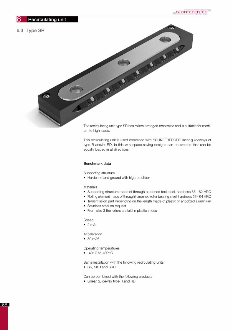
The recirculating unit type SR has rollers arranged crosswise and is suitable for medi-um to high loads.
This recirculating unit is used combined with SCHNEEBERGER linear guideways of type R and/or RD. In this way space-saving designs can be created that can be equally loaded in all directions.
Benchmark data
Supporting structure• Hardened and ground with high precision
Materials• Supporting structure made of through hardened tool steel, hardness 58 - 62 HRC• Rolling element made of through hardened roller bearing steel, hardness 58 - 64 HRC• Transmission part depending on the length made of plastic or anodized aluminium• Stainless steel on request• From size 3 the rollers are laid in plastic shoes
Speed• 2 m/s
Acceleration• 50 m/s2
Operating temperatures• -40o C to +80o C
Same installation with the following recirculating units• SK, SKD and SKC
Can be combined with the following products• Linear guideway type R and RD
Recirculating unit
6.3 Type SR

69
6
A-A
B-B
A
A
B
BL3
L1
Kt
L
L3L3
L1
f1
m
f e J
o
g
B
N
dF
Dw
B/2
2C
c
A-A
B-B
A
A
B
BL3
L1
Kt
L
L3L3
L1
f1
m
f e J
o
g
B
N
dF
Dw
B/2
2C
c
6.3
Typ
e S
R
Lube hole
Recirculating unit
Dimensions and load capacities of type SR
Type and size Wei
ght i
n g
B Dw F J Kt
L L1
L3
N d e f f1
g m o C in N Optio
ns
(see
cha
pter
8)
SR 2-032 10 6 2 9.8 9.5 16 32 15 - 6 4.4 M3 2.55 - 4 - 1 380 GP
SR 3-075 50 8 3 15 14.5 46 75 25 12.5 9 6 M4 3.3 1.5 4.9 11.8 1.3 850 GP
SR 6-100 21015 6 25.7 24.5
56 100 5025 15 9.5 M6 5.2 2 9.8 19.7 2.5
2'150GP
SR 6-150 310 105 150 28.9 3'750
SR 9-150 750 22 9 40.5 39 92 150 100 50 26 10.5 M8 6.8 3 15.8 32.4 3.5 5'850 GP
SR 12-200 1'580 28 12 51.5 49 112 200 100 50 32 13.5 M10 8.5 3 19.8 40.2 4 10'000 GP The types in bold are standard. Type SR 12 is available on request
70
6
A
e1
A1+- 0.5
0
+- 0.3
0
R
RD
SR
SR SR
Q
MQ ML
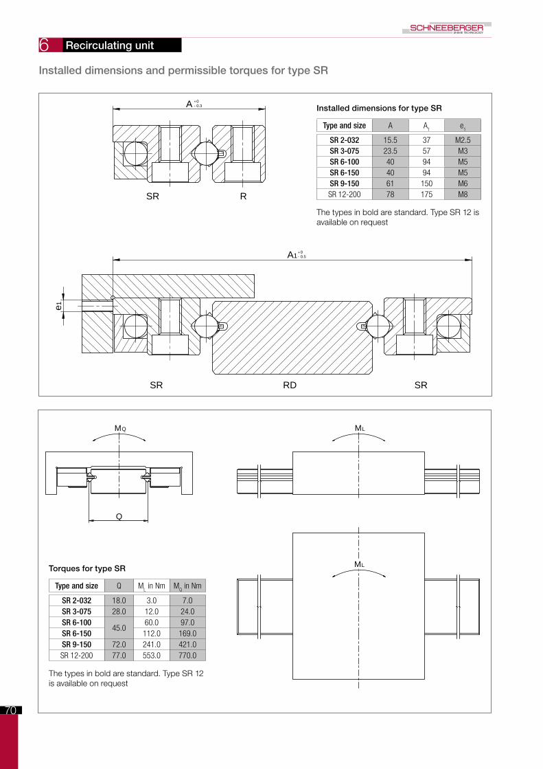
MLTorques for type SR
Type and size Q ML in Nm M
Q in Nm
SR 2-032 18.0 3.0 7.0SR 3-075 28.0 12.0 24.0SR 6-100
45.060.0 97.0
SR 6-150 112.0 169.0SR 9-150 72.0 241.0 421.0SR 12-200 77.0 553.0 770.0
The types in bold are standard. Type SR 12 is available on request
Installed dimensions for type SR
Type and size A A1
e1
SR 2-032 15.5 37 M2.5SR 3-075 23.5 57 M3SR 6-100 40 94 M5SR 6-150 40 94 M5SR 9-150 61 150 M6SR 12-200 78 175 M8
The types in bold are standard. Type SR 12 is available on request
Installed dimensions and permissible torques for type SR
Recirculating unit

71
6
This roller recirculating unit is designed for medium to heavy loads. Demanding solutions can be created together with the suitable linear guideways.
Advantages/benefits of the NRT
• Two independent tracks, the small amount of roller play and the optimal ratio of roller length and roller diameter are responsible for minimal lateral forces.
• The large number of rollers and the optimised roller run-ins are responsible for minimal travel pulsation and a low coefficient of rolling friction
• High degree of rigidity thanks to three-point support on the rear• Protected roller return• Double-lipped wipers on each side• Can also be supplied matched as an option, sorted within 5µm
Advantages/benefits of the preload wedge NRV
This preload wedge is used for setting preload. The NRV with its concave and convex supporting surfaces is also able to even out minor angular errors and defor-mations in the connecting structure.
Benchmark data
Supporting structure• Hardened and ground with high precision
Materials• Supporting structure made of through hardened tool steel, hardness 58 - 62 HRC• Rolling element made of through hardened roller bearing steel, hardness 58 - 64 HRC• Transmission parts and wipers made of plastic
Speed• 1 m/s
Acceleration• 50 m/s2
Operating temperatures• -40o C to +80o C
Recirculating unit type NRT Preload wedge type NRV
6.4 Type NRT (with NRV)
6.3
/ 6.
4 Ty
pe
NR
T (w
ith N
RV
)
Recirculating unit

72
6
bb1
L1 L3
d1 N
d
A
H L6
L5
L2 L1
L4
L
N
e1
f
e
B
g
2
1
3
+- 0.1
+ -0.1
+0- 0.2
N
L1
Kt
L2
L
m
11
2G
Dw
d
Lw
f e
B
g1
g
A
+ -
+-
0 0.1
00.025
+- 0.1
f1
C+ - 0.
1
+- 0.1
+ - 0.
1
Double-sided lubrication opening with lube nipple
ø4 type D1a
Dimensions and load capacities of type NRT
Recirculating unit
Recirculating unit type NRT
Type and size Wei
ght i
n g
A B Dw G Kt
L L1
L2
Lw
N d e f f1
g g1
m C in N Optio
ns
(see
cha
pter
8)
NRT 19077 185 19 27 5 18.85 45 77 25.5 49.2 13 20.6 6 M4 3.3 6 15.5 6 5.3 43'000GPZS
NRT 26111 57026 40 7 25.85
70 111 44 75.619 30 8 M6 5 9
2010 10.3
98'000GPZS
NRT 26132 721 91 132 68 96.6 20.6 120'000GPZS
NRT 38144 1'390 38 52 10 37.8 90 144 51 96.8 26 41 11 M8 6.8 11 29 14 14.5 181'000GPZS
1
2

73
6
bb1
L1 L3
d1 N
d
A
H L6
L5
L2 L1
L4
L
Ne1
f
e
B
g
2
1
3
+- 0.1
+ -0.1
+0- 0.2
N
L1
Kt
L2
L
m
11
2G
Dw
d
Lw
f e
B
g1
g
A
+ -
+-
0 0.1
00.025
+- 0.1
f1
C+ - 0.
1
+- 0.1
+ - 0.
1
bb1
L1 L3
d1 N
d
A
H L6
L5
L2 L1
L4
L
N
e1
f
e
B
g
2
1
3
+- 0.1
+ -0.1
+0- 0.2
N
L1
Kt
L2
L
m
11
2G
Dw
d
Lw
f e
B
g1
g
A
+ -
+-
0 0.1
00.025
+- 0.1
f1
C+ - 0.
1
+- 0.1
+ - 0.
1
bb1
L1 L3
d1 N
d
A
H L6
L5
L2 L1
L4
L
N
e1
f
e
B
g
2
1
3
+- 0.1
+ -0.1
+0- 0.2
N
L1
Kt
L2
L
m
11
2G
Dw
d
Lw
f e
B
g1
g
A
+ -
+-
0 0.1
00.025
+- 0.1
f1
C+ - 0.
1
+- 0.1
+ - 0.
1
Setting screw
Lubricating aperture
locking and jacking screws
Dimensions and load capacities of type NRV
Recirculating unit
Preload wedge NRV
Type and size W
eigh
t in
g
A B H max. L max. L1
L2
L3
L4 max. L
5L
6N b b
1d d
1e e
1f g
NRT 19077 195 16 27 7 72 25.5 22.5 16.5 68 61 56 20.6 7 9 7 9 M4 M3 3.3 4.5
NRT 26111 67025 40 8
105 44 29 21 98 90 8330 9
17.58 11 M6 M4 5 8
NRT 26132 837 126 68 27.5 19.5 119 111 104 29.5
NRT 38144 1'300 30 52 8 130 51 37.5 28.5 121 113 105 41 10 20.5 11 14 M8 M6 6.8 8 6.4
Typ
e N
RT
(with
NR
V)
1
2
3

74
75
7
0 200 400 600 800 1000
L (mm)
10
8
6
4
2
(µm)
2000 2200 2400 2600 2800 30001800160014001200
12
14
16
18
20
NQ
SQ
SSQ
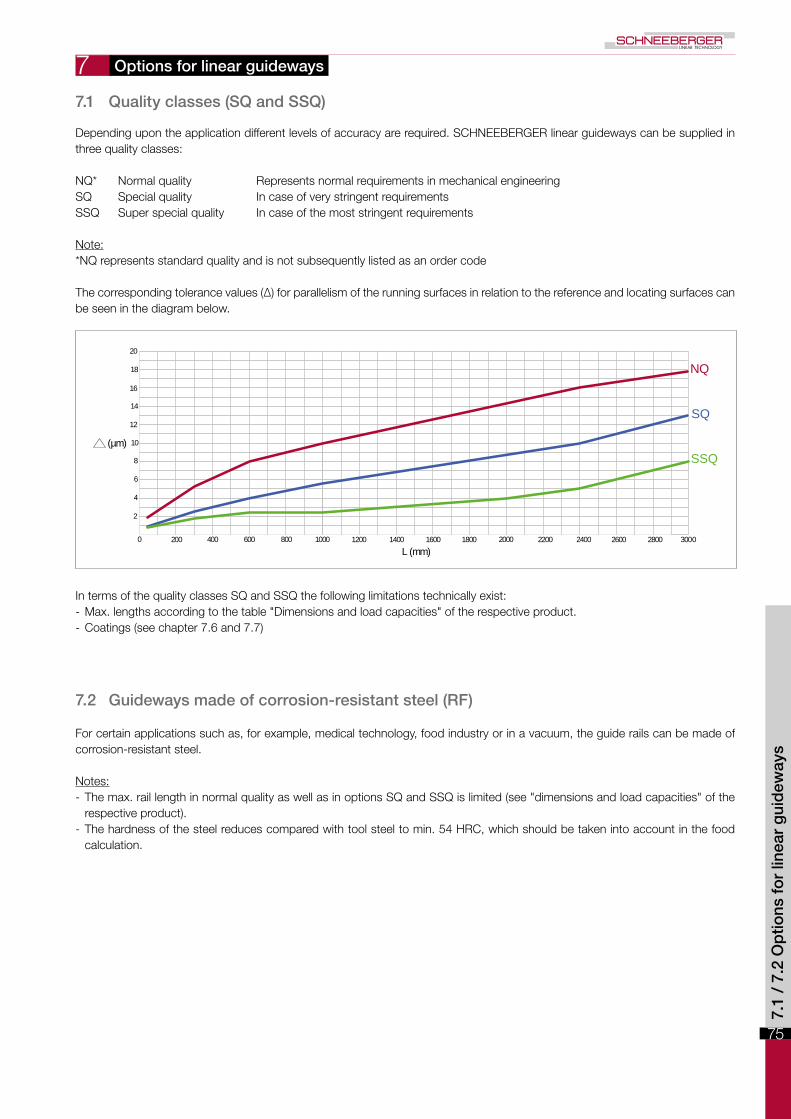
Depending upon the application different levels of accuracy are required. SCHNEEBERGER linear guideways can be supplied in three quality classes:
NQ* Normal quality Represents normal requirements in mechanical engineeringSQ Special quality In case of very stringent requirementsSSQ Super special quality In case of the most stringent requirements
Note:*NQ represents standard quality and is not subsequently listed as an order code
The corresponding tolerance values (Δ) for parallelism of the running surfaces in relation to the reference and locating surfaces can be seen in the diagram below.
In terms of the quality classes SQ and SSQ the following limitations technically exist: - Max. lengths according to the table "Dimensions and load capacities" of the respective product. - Coatings (see chapter 7.6 and 7.7)
7.2 Guideways made of corrosion-resistant steel (RF)
For certain applications such as, for example, medical technology, food industry or in a vacuum, the guide rails can be made of corrosion-resistant steel.
Notes: - The max. rail length in normal quality as well as in options SQ and SSQ is limited (see "dimensions and load capacities" of the respective product).
- The hardness of the steel reduces compared with tool steel to min. 54 HRC, which should be taken into account in the food calculation.
Options for linear guideways
7.1 Quality classes (SQ and SSQ)
7.1
/ 7.
2 O
ptio
ns f
or
linea
r g
uid
eway
s

76
7
Overrunning cages are expedient if a short table is to be moved on a long guideway track. As a result the upper part is at any time supported over its entire length, which has a positive effect on the load carrying capacity and rigidity.
7.4 Multi-part linear guideways (ZG)
Is the desired overall length of the guideway is greater than the maximum length listed in this catalogue, individual rails can be ground together. The offset between the individual guideway tracks for this is max. 0.002 mm. The length tolerance L is within +/- 2 mm.
During installation it is important to pay attention to the numbering at the butt joint.
SO that the cage run-in causes as little pulsation as possible, the short rails are pro-vided with rounded run-ins. The run-ins are ground following manufacture of the guide-way track.
Note:On rare occasions (e.g. under very high preload), in spite of rounded run-ins the pul-sation of the overrunning cage can have a disruptive effect on the application. This phenomenon can be largely eliminated by taking appropriate measures (on request).
1 1 2 2
3 3 4 4
L
Options for linear guideways
7.3 Run-ins rounded (EG)

77
A2
A1
2
2
1
1
A2
A1
2
2
1
1
7
7.6 DURALLOY ® coating (DU)
For applications in which a corrosion protection and/or increased wear resistance of the surfaces is required, it is recommended to coat the guideways with DURALLOY®.
Technical information - Max. rail length 2000 mm - Hardness HRC 64 - 74 - Coating thickness 2.5 – 4.0 µm - Structure "Pearlescent" (see figure) - Vacuum-compatible 10-7 mbar
The advantages of DURALLOY®
- Increased wear resistance - Corrosion protection - The pearl structure acts as a lubricant reservoir - Good emergency running characteristics - Protection from abrasive corrosion - High degree of chemical resistance
Options for linear guideways
7.5 Height-matched guideways (HA)
The tolerance of height A is as standard 0/-0.3 mm. In the case of surface-mounted guideways, which must be matched to the same height, A (and/or A1 and A2) is made in consignments with a tolerance of +/- 0.01 mm.
The rails are identified/numbered correspondingly. If multiple consignments are supplied, they are given serial numbers.
Notes: - The ZG special versions (multi-part linear guideway) and the maximum quality grade SSQ are not possible. - Special quality SQ only on request
7.5
/ 7.
6 O
ptio
ns f
or
linea
r g
uid
eway
s
78
7 7.7 DryRunner coating (DR and DRC1)
Without lubrication the running surfaces of linear guideways are completely destroyed after only 10'000 passes.
A guideway coated with DryRunner supports more than 100 million passes and thus a service life extended by 10'000 times - without lubrication. In vacuum an unlubricated guideway coated with DryRunner supports more than 50 million passes.
DryRunner coated linear guideways can of course be used with standard lubricants, which means the previously listed running performance statistics increase considerably.
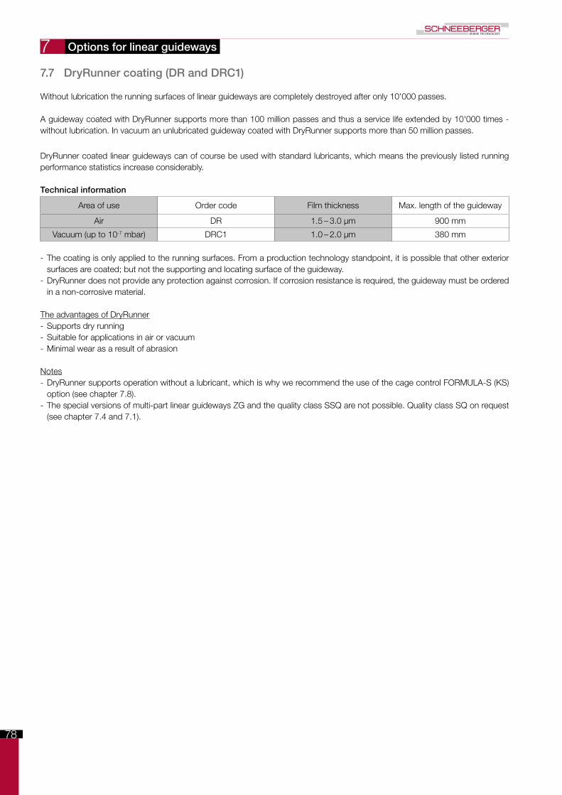
Technical information
Area of use Order code Film thickness Max. length of the guideway
Air DR 1.5 – 3.0 µm 900 mm
Vacuum (up to 10-7 mbar) DRC1 1.0 – 2.0 µm 380 mm
- The coating is only applied to the running surfaces. From a production technology standpoint, it is possible that other exterior surfaces are coated; but not the supporting and locating surface of the guideway.
- DryRunner does not provide any protection against corrosion. If corrosion resistance is required, the guideway must be ordered in a non-corrosive material.
The advantages of DryRunner - Supports dry running - Suitable for applications in air or vacuum - Minimal wear as a result of abrasion
Notes - DryRunner supports operation without a lubricant, which is why we recommend the use of the cage control FORMULA-S (KS) option (see chapter 7.8).
- The special versions of multi-part linear guideways ZG and the quality class SSQ are not possible. Quality class SQ on request (see chapter 7.4 and 7.1).
Options for linear guideways

79
1
1
2
3
smin
B
A+ 0 - 0.3
smin
7
In every linear guideway the cage can be shifted from the centre along the longitu-dinal axis. This so-called «cage creep» can significantly impair the effectiveness of your application. On the one hand, as a result of the displaced cage the optimal load distribution is no longer guaranteed and, on the other, the cage must be cen-tred with huge expense of energy (cor-rection stroke).
The causes of cage creep
- High accelerations and speeds - Vertical installation of the guideway - Uneven load distribution - Overrunning cage - Different heat expansion coefficients - Design and installation (lacking rigidity and/or accuracy of the connecting structure)
The benefits and advantages of FORMULA-S
- Perfect load distribution - Avoids correction strokes - No force required for cage reset - Accelerations up to 300 m/s2 (30 g) - Max speed 1 m/s - Easy to install and/or uninstall - Extended service life - Vacuum-compatible up to 10-7 mbar
Suitable for the following guideways
- RN 3, RN 4 and RN 6 - RNG 4, RNG 6 and RNG 9
FORMULA-S meets the requirements fully in respect of productivity and cost-effectiveness. It is very robust and consists of only a few components.
1 Clips hold the gear rack in position (alternative fastening variants on request)
2 Rack3 Cage with pinion
Connecting structure
In the case of the connecting structure, the thickness smin should be taken into account. The remaining dimensions correspond to the guideways RN and RNG (see chapter 5, dimensions and load capacities).
7.8 Cage control FORMULA-S (KS)
Options for linear guideways
7.7
/ 7.
8 O
ptio
ns f
or
linea
r g
uid
eway
s

80
7 7.9 Cage control for N/O and M/V guideways (KZST)
The needle guideways of type N/O and M/V can be fitted with a cage control which ensures that process security is significantly increased. The causes and effects of cage creep are set out in chapter 7.8.
The benefits and advantages
- Perfect load distribution - Avoids correction strokes - No force required for cage reset - Accelerations up to 200 m/s2 (20 g) - Max. speed 1 m/s - Extended service life
This type of cage control fully meets the requirements in terms of productivity and cost-effectiveness. It is very robust, has a simple structure and consists of only a few components: A A gear rack made of tool steel per guide rail B Two pinions made of tool steel per cage
7.10 Fixing Hole Variants (V, G, or D)
The SCHNEEBERGER standardAll SCHNEEBERGER guideways have as standard a counterbore with thread (not suitable for linear guideways of type M/V). This design supports the use of a tapped fixing hole as well as the through fixing hole. The dimensions can be seen in the re-spective product specifications (chapter 5).
Options for linear guideways

81
7
N
d
T
d
1
d1
d
T
N
d
2
d
1
T
N
d
1
N
d
2
T
Special versions type V (standard for linear guideway of type M/V)
Dimensions for R-guideways
Type N Ø d T Ø d1
R 1 1.8 3 1.4 1.65R 2 2.5 4.4 2 2.55R 3 3.5 6 3.2 3.5R 6 6 9.5 5.2 5.5R 9 9 10.5 6.2 6.5R 12 12 13.5 8.2 8.5R 15 14 16.5 10.2 10.5R 18 18 18.5 12.2 12.5R 24 24 22.5 14.2 14.5
Options for linear guideways
Dimensions for RNG guideways with a cage control system (KS)
Type N Ø d T Ø d1
RNG 4-KS 3.5 6 3.2 3.5RNG 6-KS 5 7.8 3.5 4RNG 9-KS 6 8.5 4.2 4.8
Dimensions for N/O-guideways
Type N Ø d1 T Ø d2
N/O 62015 6 9.5 5.2 5.5N/O 92025 9 10.5 6.2 6.5N/O 2025 10 13.5 8.2 8.5N/O 2535 12 16.5 10.2 10.5N/O 3045 14 18.5 12.2 12.5N/O 3555 14 18.5 12.2 12.5
Dimensions for RNG-guideways
Type N Ø d T Ø d1
RNG 4 3.5 5.5 2.7 3.5RNG 6 5 7 3.2 4RNG 9 6 8.5 4.2 4.8RNG 12 8 12 6.2 7RNG 15 10 15 8.2 9RNG 20 12 18 11 10.5
Dimensions for RN-guideways
Type N Ø d T Ø d1
RN 3 3.5 6 3.2 3.5RN 4 4.5 8 4.1 4.5RN 6 6 9.5 5.2 5.5RN 9 9 10.5 6.2 6.5RN 12 12 13.5 8.2 8.5RN 15 14 16.5 10.2 10.5RN 18 18 18.5 12.2 12.5RN 24 24 22.5 14.2 14.5
7.9
/ 7.
10 O
ptio
ns f
or
linea
r g
uid
eway
s

82
7
N
e d
f3
N
e2
N
e2
f3
Special versions type G
Dimensions for R-guideways
Type N e Ø d
R 1 1.8 M2 1.65R 2 2.5 M3 2.55R 3 3.5 M4 3.3R 6 6 M6 5.2R 9 9 M8 6.8R 12 12 M10 8.5R 15 14 M12 10.5R 18 18 M14 12.5R 24 24 M16 14.5
Dimensions for RN-guideways
Type N e Ø d
RN 3 3.5 M4 3.3RN 4 4.5 M5 4.3RN 6 6 M6 5.2RN 9 9 M8 6.8RN 12 12 M10 8.5RN 15 14 M12 10.5RN 18 18 M14 12.5RN 24 24 M16 14.5
Dimensions for RNG-guideways
Type N e Ø d
RNG 4 3.5 M3 2.65RNG 6 5 M4 3.3RNG 9 6 M5 4.4RNG 12 8 M8 6.8RNG 15 10 M10 8.5RNG 20 12 M12 10.5
Dimensions for N/O-guideways
Type N e2 Ø f3
N/O 62015 6 M6 5.2N/O 92025 9 M8 6.8N/O 2025 10 M10 8.5N/O 2535 12 M12 10.5N/O 3045 14 M14 12.5N/O 3555 14 M14 12.5
Options for linear guideways

83
7
f3
N
e2e2
g
f4
N
N
e2
f3
e2
g
f4
N
Dimensions for M/V-guideways
Type N e2 g Ø f3 Ø f4
M/V 3015 5.5 M4 - 3.2 -
M/V 4020 7.5 M6 - 5.2 -
M/V 5025 10 M6 15 5.2 5
M/V 6035 11 M8 20 6.8 6.8
M/V 7040 13 M10 25 8.5 8.5
M/V 8050 14 M12 30 10.5 10.3
Options for linear guideways
7.10
Op
tions
fo
r lin
ear
gui
dew
ays

84
7
d
1
N
f2
N N
f2
Special versions type D
Options for linear guideways
Dimensions for R-guideways
Type N Ø d1
R 1 1.8 1.65R 2 2.5 2.55R 3 3.5 3.5R 6 6 5.5R 9 9 6.5R 12 12 8.5R 15 14 10.5R 18 18 12.5R 24 24 14.5
Dimensions for RN-guideways
Type N Ø d1
RN 3 3.5 3.5RN 4 4.5 4.5RN 6 6 5.5RN 9 9 6.5RN 12 12 8.5RN 15 14 10.5RN 18 18 12.5RN 24 24 14.5
Dimensions for RNG-guideways
Type N Ø d1
RNG 4 3.5 3.5RNG 6 5 4RNG 9 6 4.8RNG 12 8 7RNG 15 10 9RNG 20 12 10.5
Dimensions for N/O-guideways
Type N Ø f2
N/O 62015 6 5.5N/O 92025 9 6.5N/O 2025 10 8.5N/O 2535 12 10.5N/O 3045 14 12.5N/O 3555 14 12.5
Dimensions for M/V-guideways
Type N Ø f2
M/V 3015 5.5 5.3M/V 4020 7.5 7.5M/V 5025 10 7.5M/V 6035 11 10M/V 7040 13 12.5M/V 8050 14 14
85
8 B
A
A
SK, SKD, SKC, SR
NRT
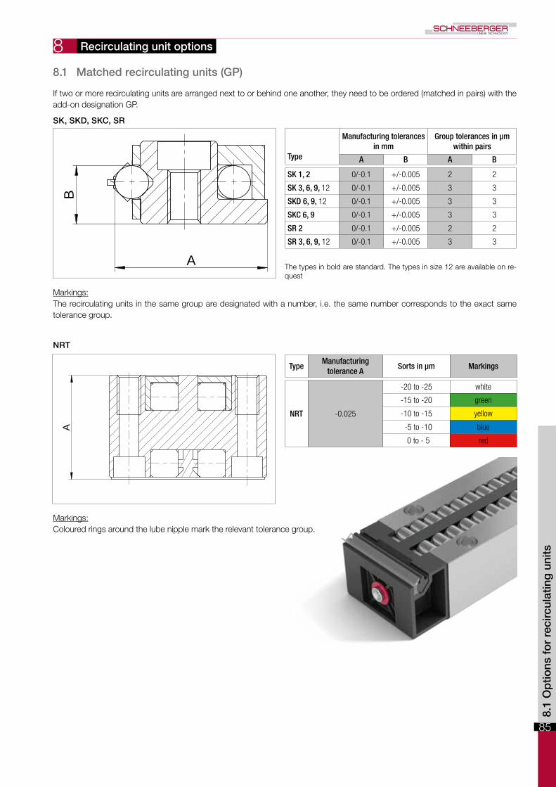
If two or more recirculating units are arranged next to or behind one another, they need to be ordered (matched in pairs) with the add-on designation GP.
Markings:The recirculating units in the same group are designated with a number, i.e. the same number corresponds to the exact same tolerance group.
Markings:Coloured rings around the lube nipple mark the relevant tolerance group.
Recirculating unit options
8.1 Matched recirculating units (GP)
Type
Manufacturing tolerances in mm
Group tolerances in µm within pairs
A B A B
SK 1, 2 0/-0.1 +/-0.005 2 2
SK 3, 6, 9, 12 0/-0.1 +/-0.005 3 3
SKD 6, 9, 12 0/-0.1 +/-0.005 3 3
SKC 6, 9 0/-0.1 +/-0.005 3 3
SR 2 0/-0.1 +/-0.005 2 2
SR 3, 6, 9, 12 0/-0.1 +/-0.005 3 3
TypeManufacturing
tolerance ASorts in µm Markings
NRT -0.025
-20 to -25 white
-15 to -20 green
-10 to -15 yellow
-5 to -10 blue
0 to - 5 red
The types in bold are standard. The types in size 12 are available on re-quest
8.1
Op
tions
fo
r re
circ
ulat
ing
uni
ts

86
8
z
s s1
m
f
L
Connection variants
8.2 Centralised lubricating system (ZS) for recirculating units NRT
Recirculating unit options
Wrench size
Type Size L f m s s1 z
NRT 19077ZS-2 13 2
5.3 8 710.5
ZS-3 14.5 3 11
NRT 26111 NRT 26132
ZS-2 13 2
10.3
8 710.5
ZS-3 14.5 3 11
ZS-4 18.5 410 8
14ZS-5 19 5
ZS-6 20 6 12 10
NRT 38144
ZS-2 13 2
14.5
8 710.5
ZS-3 14.5 3 11
ZS-4 18.5 410 8
14ZS-5 19 5
ZS-6 20 6 12 10

87
9
ɅA
±0.005
ɅBA
B
±0.005
ɅB
ɅA
A
B
±0.005
B
A ɅB
ɅA
Ʌ
The running and positioning accuracy of an application directly depends on the geometric precision of the guideway (see chapter 7.1), its careful orientation (see chapter 14.9) and the accuracy and rigidity of the surrounding structure (see chapter 14.1 / 14.2).
9.2 Tolerance of the supporting surface to the track
In addition to the previously mentioned geometric precision as set out in chapter 7.1, SCHNEEBERGER guideways are also man-ufactured to the dimensions of the supporting surface in relation to the track within a very tight tolerance (+/- 0.005mm).
Its advantages:• Interchangeability is guaranteed at all times.• In most cases additional matching of the guideways is surplus to requirement.
Linear guideways standard parameters
9.1 Quality classes
8.2
/ 9.
1 S
td. p
aram
eter
s fo
r lin
ear
gui
dew
ays
Type R, RN and RNG
Type N/O and M/V
Type RD

88
9
L1
L
0X1
X2
X3
X4
Xn
9.4 Operating temperatures
SCHNEEBERGER linear guideways can be used at operating temperatures from –40º C to +80º C. For brief periods temperatures up to +120º C are possible.
9.5 Speeds and accelerations
The following limit values apply for the standard designs:
Product max. speed max. acceleration
Linear guideways R, RD, RN,RNG, N/O and M/V 1 m/s 50 m/s2
Linear guideways RN and RNG withCage control FORMULA-S 3 m/s 300 m/s2
Linear guideways N/O and M/V withcage control 3 m/s 200 m/s2
9.6 Friction, running accuracy and smoothness
When manufacturing the linear guideways, SCHNEEBERGER places great value on a high level of smoothness. Transitions, run-ins and run-outs or the quality of the synthetic materials and synthetic composite cages are given top priority. This also applies in re-spect of the rolling elements used, which must satisfy the most stringent quality demands.
For guideways with cages under normal operating conditions a friction factor of 0.0005 to 0.0030 can be assumed.
Length L ≤300 mm: ±0.3 mmLength L >300 mm: ±0.1 % of L
Hole pitch L1: ±0.3 mmMass Xn ≤350 mm: ±0.3 mmMass Xn >350 mm: ±0.08 % of xn
The fixing holes are manufactured before the hardening process, which is why the length tolerances and spacings differ from the usual standards. The deviations can be offset using undercut fastening screws of type GD or GDN (see chapter 5) and/or by choosing a suitable hole (see chapter 7.10).
9.3 Length tolerances and distances between fixing holes
Linear guideways standard parameters
89
10
SCHNEEBERGER recirculating units can be used at operating temperatures from –40º C to +80º C (for brief periods temperatures up to +120º C are possible). For type SKC the temperature range is –150º C to +200º C.
10.2 Speeds and accelerations
The following limit values apply for the standard designs:
Product max. speed max. acceleration
SK, SKD, SKC and SR 2 m/s 50 m/s2
NRT 1 m/s 50 m/s2
10.3 Friction, running accuracy and smoothness
When manufacturing the recirculating units, SCHNEEBERGER places great value on a high level of smoothness. Transitions, run-ins and run-outs or the quality of the synthetic materials are given top priority. This also applies in respect of the rolling elements used, which must satisfy the most stringent quality demands.
For recirculating units under normal operating conditions a friction factor of 0.005 can be assumed.
Recirculating unit standard parameters
10.1 Operating temperatures
9.3
/ 10
.1 S
td. p
aram
eter
s fo
r re
circ
ulat
ing
uni
ts

90
11
wttzDw
K
Kt
C
C
The versatile areas of application assume different characteristics from linear guideways and recirculating units.Various parameters and considerations essential for product selection. These are set out in detail below.
11.1 Linear guideways Relationship between stroke H and length of the guideway L
If the stroke is below 400 mm, the following formula applies:
H < 0.7L
If the stroke is above 400 mm, the following formula applies:
H < 1L
LH
= Length of the linear guideway in mm= Stroke in mm
Calculating the cage length K
K < L H2
KLH
= Cage length in mm= Length of the linear guideway in mm= Stroke in mm
The stroke must be limited by means of stops on the table and not by the cages. The stops should preferably be fitted along the axis of symmetry of the guideways to avoid additional forces acting on the linear guideways.
Calculating the number of rolling elements (RA) per cage
a) For cage types KBN, AC, AK, EE, SHW, HW
RA = K - 2w + 1t
or
RA = Kt + 1t b) For cage type KBS
RA = K - (2w + tz) + 2t
KRA
wtKt
tz
= Cage length in mm= Total available rolling element per cage= Distance from cage start to the middle of the first rolling element in mm= cage division in mm= Load-bearing length in mm= Length of the middle section for the KBS cage
Design

91
11
K
Q
L
L1
The relationship between the cage length K and the average guideway spacing Q
K > 1Q
KQ
= Cage length in mm= Average linear guideway spacing in mm
The maximum permissible installation ratio in the case of overrunning cages
Overrunning cages are expedient if a short table is to be moved on a long guideway track. In each case the short rail for the guideway must have a rounded run-in (special version EG, see chapter 7.3) so that the overrunning cage causes as little pulsation as possible.
Not every cage is suitable for this application. The maximum cage overrun depends on the position of the rails and on the cage material.
Maximum permitted installation ratios L to L1:– for fixed guideways 1 : 2– for laid on guideways 1 : 4
Design
11.1
Des
ign

92
11
H/2L
Ltot
an anK
L
H/2
H H
L1
Ltot
anan K H/2L
Installation variants for linear guideways with wipers
For different linear guideways wipers can be used in the form of end pieces (an). Two installation variants are possible for this. In both instances this results in the following length ratios:
Variant 1
Roller guideways with end pieces/wipers and rails equal in length:K = L – H/2 – an
Lto = L + H/2 + an
With this design the linear guideways must be fitted offset by the amount an.
Variant 2
Roller guideways with end pieces/wipers and rails not equal in length:K = L – H/2Ltot = L1 + H/2 (if the long guideway moves)Ltot = L1 (if the short guideway moves)
KHLL1
Lto
an
= Cage length in mm= Stroke in mm= Length in mm= Length in mm= Total length in mm= Thickness of the end piece in mm
Design

93
11
Kt
K
Q
When using recirculating units, theoretically there is not restriction in stroke. The stroke is only restricted by the length of the guide rails.
In terms of the spacing K between the recirculating units and the rail spacing Q, the following ratios are recommended as a guideline:
When using one recirculating unit per rail: Kt > 1Q
When using more than one recirculating unit per rail: K > 1Q
KKt
Q
= Spacing between the recirculating units in mm= Load-bearing length in mm= Average rail spacing in mm
Design
11.2 Recirculating units
11.2
Des
ign

94
95
12
The loading capacities are based on the principles specified by the ISO and DIN for calculation of roller-contact bearings (DIN ISO 14728).
In accordance with DIN in most applications a permanent overall deformation of 0.0001 times the rolling element diameter can be permitted without adversely affecting the operating behaviour of the bearing. Consequently, the static loading capacity C0 is set sufficiently high that the aforementioned deformation occurs approximately when the equivalent static load corresponds to the static loading capacity. So that the afore-mentioned overall deformation does not occur it is recommended being guided by the dynamic loading capacity C.
The dynamic loading capacity C is the load at which a nominal service life L of 100'000 m travel distance is achieved. It is important to note when calculating the service life that not only the load, which acts vertically on the guideway, should be taken into account but the load range of all acting forces and moments.
The service life corresponds to the travel distance in metres, which is travelled from a guideway. And this is before the first sign of material fatigue occurring to one of the roller guideway elements involved. The nominal service life is achieved when 90% of the guideways of identical construction reach or exceed the corresponding travel distances under normal operating conditions.
Critical for the dimensioning of the guideways are the loads occurring in the ratio with the dynamic loading capacity C.
Definition of service life
As previously mentioned, the dynamic loading capacity C100 is based on a service life of 100'000 m. Other manufacturers frequently indicate the loading capacity C50 for a service life of 50'000 m. The resulting load capacities from this are more than 20% higher than specified in the DIN ISO standard.
Conversion examples
For ballsConvert load capacities in accordance with DIN ISO standard to C50:C50 = 1.26 ∙ C100
Convert C50 load capacities in accordance with DIN ISO standard to:C100 = 0.79 ∙ C50
For rollers and needlesConvert load capacities in accordance with DIN ISO standard to C50:C50 = 1.23 ∙ C100
Convert C50 load capacities in accordance with DIN ISO standard to:C100 = 0.81 ∙ C50
C50 C100
= dynamic loading capacity C in N for 50'000 m of travel distance= dynamic loading capacity C in N for 100'000 m of travel distance, defined in accordance with DIN ISO standard
Load carrying capacity and service life
12.1 Basic principles
12.1
Lo
ad c
arry
ing
cap
acity
and
ser
vice
life

96
12
1
1 2 3 4
2 3
1
1
2
2
3
3
4
4
Load carrying capacity and service life
We talk about short stroke applications when a rolling element does not travel past the position of the next rolling element during a stroke.
Because the tracks are concentrated at these points (depressions from wear and tear form), the precision and service life of the guideway is reduced. When the strokes are highly frequent, a standard lubricant is no longer able to reach the points of contact.
Wear and tear can be deferred with suitable lubricants and regular lubrication strokes.
Short strokes curtail the service life of the guideway considerably. The service life of the guideway(s) can only be determined by means of tests.
12.2 Short strokes
Normal stroke
Short stroke
A continuous lubricating film forms be-low the rolling element
Local depressions from wear and tear form on the tracks. At highly frequent strokes the lubricating film is also interrupted

97
12
The formulae for calculating service life are:
For rollers and needles:
L = a∙�Ceff �10
∙ 105 m3
P
For balls:
L = a∙�Ceff �3
∙ 105 mP
aCeff
PL
= Event probability factor= Effective load carrying capacity per rolling element in N= Dynamic, equivalent load in N= Nominal service life in m
Event probability a
The load carrying capacities for roller-contact bearings correspond to the DIN ISO standard. This represents a value from the service life calculation, which is exceeded with a probability of 90% during operational use of the guideway.
If the previously mentioned theoretical service life probability factor of 90% is not adequate, the service life values will need to be adjusted by a factor a.
Event probability in % 90 95 96 97 98 99
Factor a 1 0.62 0.53 0.44 0.33 0.21
Effective load carrying capacity Ceff
External influences such as track hardness and temperature can reduce the loading capacity C which means that Ceff needs to be calculated.
Ceff = fH · fT · C
Ceff
fHfTC
= Effective load carrying capacity per rolling element in N= Hardness factor= Temperature factor= Max. permissible load carrying capacity per rolling element in N
Load carrying capacity and service life
12.3 Calculating the service life L in accordance with the DIN ISO standard
12.2
/ 12
.3 L
oad
carr
ying
cap
acity
and
ser
vice
life

98
12 Load carrying capacity and service life
Hardness factor fH
Materials in a frictionless guideway, which deviate from the standard conditions (HRC 58 - 62), can be recorded with the factor fH:
Track hardness in HRC 20 30 40 50 54 56 57 58-62
Hardness factor fH 0.1 0.2 0.3 0.6 0.8 0.88 0.95 1
Temperature factor fT
Increased temperatures influence the operating conditions (material properties) and must be taken into account using the factor fT.
Temperature of the guideway in °C 150 200 250 300
Temperature factor fT 1 0.9 0.75 0.6
Example calculation for Ceff
Guideway type R6 => Hardness 58 - 62 HRC => fH = 1Temperature 200°C => fT = 0.9Cage AA 6 => C = 530 N per roller
Ceff = fH · fT · C = 1 · 0.9 · 530 = 477 N

99
12
F1
L1 LnL2
F2
Fn
Dynamically equivalent load P
The loads (F) acting on a linear guideway system are subject to frequent fluctuations during operation. This set of circumstances should be taken into account when calculating service life. The varying load absorption of the guideway at varying operating con-ditions during the travel distance is described as being the dynamic equivalent load P.
Stepped loadFormula for rollers and needles:
P =10
�1(F1
10·L1 +F2
10·L2 +...F𝑛
10·L𝑛)3 3 3 3
L
Formula for balls:
P =3
�1(F1
3·L1 +F2
3·L2 + ... F𝑛
3·L𝑛)L
Sinusoidal loadP = 0.7 Fmax
PF1... Fn
Fmax
LL1... Ln
= Equivalent load in NIndividual load in N during the partial travel distance L …. Ln
= Max. load in N= L1 + …+ Ln = total travel during one load cycle in mm= partial travel distance in mm of one individual load during a load cycle
Example calculation with a linear guideway of type RNG 6-300 with KBN 6 cage
• an event probability of 97% is selected; the corresponds to a factor a of 0.44• the dynamic loading capacity of a roller (for KBN 6 cage) is 1'800 N. If 16 rollers are used, the loading capacity of the
guideway is 16 ∙ 1'800 N = (28'800 N)• the application generates a total load on to the guideway of 10'000 N
With the previously mentioned values, the following calculation for service life L is:
L = a ∙� Ceff �10
∙ 1053
P
L = 0.44 ∙�28'800 N�10
∙ 105 = 1'495'412 𝓂3
10'000 N
If the service life is requested in hours, the travelled stroke H (in meters) and the time t (in seconds) required for the stroke movement must be known.
The service life Lh is calculated as follows:
Lh = L ∙ � = Service life in hoursH ∙ 3'600
Load carrying capacity and service life
Total travel distance L
Total travel distance L
Load
PLo
ad P
12.3
Lo
ad c
arry
ing
cap
acity
and
ser
vice
life