linear beam power amplifier tube - relltubes.com · power tube linear beam power amplifier tube...
TRANSCRIPT
Power Tube
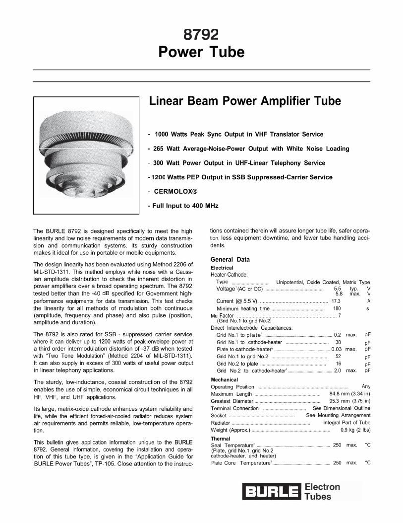
Linear Beam Power Amplifier Tube
1000 Watts Peak Sync Output in VHF Translator Service
265 Watt Average-Noise-Power Output with White Noise Loading
300 Watt Power Output in UHF-Linear Telephony Service
Watts PEP Output in SSB Suppressed-Carrier Service
CERMOLOX®
Full Input to 400 MHz
The BURLE 8792 is designed specifically to meet the highlinearity and low noise requirements of modern data transmis-sion and communication systems. Its sturdy constructionmakes it ideal for use in portable or mobile equipments.
The design linearity has been evaluated using Method 2206 ofMIL-STD-1311. This method employs white noise with a Gauss-ian amplitude distribution to check the inherent distortion inpower amplifiers over a broad operating spectrum. The 8792tested better than the -40 specified for Government performance equipments for data transmission. This test checksthe linearity for all methods of modulation both continuous(amplitude, frequency and phase) and also pulse (position,amplitude and duration).
The 8792 is also rated for SSB suppressed carrier servicewhere it can deliver up to 1200 watts of peak envelope power ata third order intermodulation distortion of -37 when testedwith “Two Tone Modulation” (Method 2204 of MIL-STD-1311).It can also supply in excess of 300 watts of useful power outputin linear telephony applications.
The sturdy, low-inductance, coaxial construction of the 8792enables the use of simple, economical circuit techniques in allHF, VHF, and UHF applications.
Its large, matrix-oxide cathode enhances system reliability andlife, while the efficient forced-air-cooled radiator reduces systemair requirements and permits reliable, low-temperature opera-tion.
This bulletin gives application information unique to the BURLE8792. General information, covering the installation and opera-tion of this tube type, is given in the “Application Guide forBURLE Power Tubes”, TP-105. Close attention to the
tions contained therein will assure longer tube life, safer opera-tion, less equipment downtime, and fewer tube handling acci-dents.
General DataElectricalHeater-Cathode:
.............................. Unipotential, Oxide Coated, Matrix TypeVoltage1 (AC or DC) .............................................. 5.5 typ. V
5.8 max.Current 5.5 ................................................ 17.3 AMinimum heating time .......................................... 180 s
Mu Factor ...................................................................... 7(Grid No.1 to grid
Direct Interelectrode Capacitances:Grid No.1 to p la te2 .............................................................. 0.2 max.Grid No.1 to cathode-heater .................................. 38 pFPlate to .................................................. 0.03 max.Grid No.1 to grid No.2 ............................................ 52 pFGrid No.2 to plate .................................................... 16 pFGrid No.2 to cathode-heater2 ........................................ 2.0 max.
MechanicalOperating Position ........................................................................Maximum Length .................................................... 84.8 mm (3.34 in)Greatest Diameter .................................................... 95.3 mm (3.75 in)Terminal Connection .................................. See Dimensional OutlineSocket .................................................... See Mounting ArrangementRadiator .............................................................. Integral Part of TubeWeight (Approx.) .............................................................. 0.9 kg (2 Ibs)
ThermalSeal Temperature3 .................................................................. 250 max. °C(Plate, grid grid No.2cathode-heater, and heater)Plate Core Temperature3 .................................................... 250 max. °C
Linear RF Power Amplifier1
Single-Sideband, Suppressed-Carrier ServiceMaximum CCS Ratings, Absolute-Maximum Values
Up to 400 MHzDC Plate Voltages1 .......................................................................... 3500 VDC Grid-No.2 Voltage1 .................................................................. 1000 VDC Plate Current at Peak of Envelope4 .................................. 1.25 AGrid-No.2 Input1 ...................................................................................... 50 WPlate Dissipation ................................................................ 1.8
Maximum Circuit ValuesGrid-No.1 Circuit Resistance:
fixed bias ............................................................ 5000 ohms cathode bias .......................................... Not Recommended
Grid-No.2 Circuit Impedance ............................................ See note 1Plate Circuit Impedance .................................................... See note 1
Typical Class AB, CCS Operation with“Two-Tone” Modulation
In a grid-drive circuit at 30 MHzDC Plate Voltage ............................................ 2500 2500 VDC Grid-No.2 Voltage ...................................... 600 600 VDC Grid-No.1 .................................................. -65 -61 VZero-Signal DC Plate Current ............................ 0.5 0.6 AEffective RF Load Resistance ........................ 1050 1050 ohmsDC Plate Current at Peak of Envelope .............. 1.O 1.1 AAverage DC Plate Current ............................... 0.85 ADC Grid-No.2 Current atPeak of Envelope .......................................... -0.020 -0.022 AAverage DC Grid-No.2 Current .................... -0.014 -0.017 APeak RF Grid-No.1 Voltage ................................ 47 VOutput Circuit Efficiency (Approx.) .................... %Useful Power Output (Approx.):
Average ........................................................ 530 WPeak envelope ............................................ 1060 1200 W
Distortion Products Level6:Third orderFifth order.. .................................................... 457 477
Unbypassed Cathode Resistor ............................ 0 0 ohm
Typical Class AB, CCS Operation withWhite Noise Loading as Specified inMethod 2206 of MIL-STD-1311
At 4.0 MHzDC Plate Voltage ............................................ 2500 2500 VDC Grid-No.2 Voltage ...................................... 600 600 VDC Grid-No. 1 Voltage ...................................... -74 -70 VZero Signal DC Plate Current ..........................RF Load Resistance ........................................ 1500 1000 ohmsAverage DC Plate Current ................................ 560 695Average DC Grid-No.2 Current ........................ -10 -11Driver Power Output8 .................................................... 4.5 8.5 WOutput Circuit Efficiency .................................... %Noise Power Ratio (NPR) .................................. -40 -40 Unbypassed Cathode Resistor ............................ 0 5 ohmsUseful Noise Power Output (NP0) .................... 200 265 W
Warning Personal Safety HazardsElectrical Shock Operating voltages applied to this devicepresent a shock hazard.
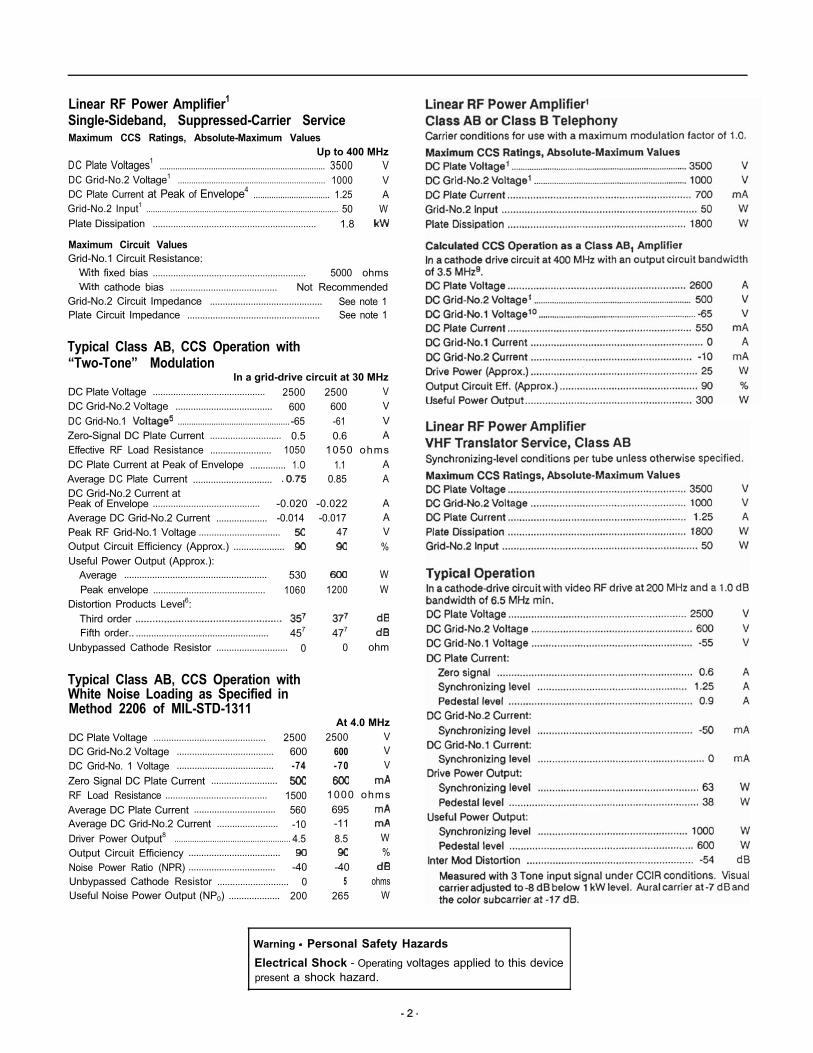
500 1000 1500 2000 2500 3000 3500
ANODE VOLTAGE VOLTS 2437
Figure 1 Typical Constant Current Characteristics(Ec2 = 600V)
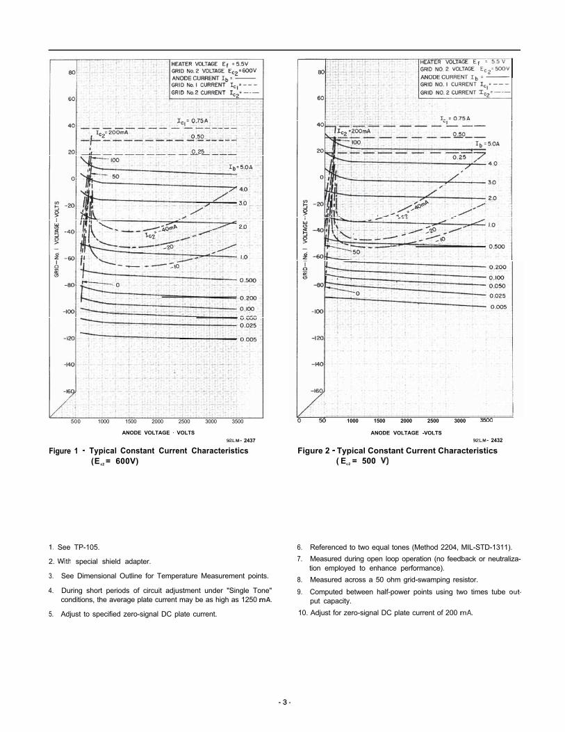
1000 1500 2000 2500 3000
ANODE VOLTAGE -VOLTS 2432
Figure 2 Typical Constant Current Characteristics( Ec2 = 500
See TP-105.
2. special shield adapter.
3. See Dimensional Outline for Temperature Measurement points.
4. During short periods of circuit adjustment under "Single Tone"conditions, the average plate current may be as high as 1250
5. Adjust to specified zero-signal DC plate current.
6. Referenced to two equal tones (Method 2204, MIL-STD-1311).7. Measured during open loop operation (no feedback or neutraliza-
tion employed to enhance performance).8. Measured across a 50 ohm grid-swamping resistor.
9. Computed between half-power points using two times tube put capacity.
10. Adjust for zero-signal DC plate current of 200
6
18
16
4
8
6 Z o = l 3 4 O H M S
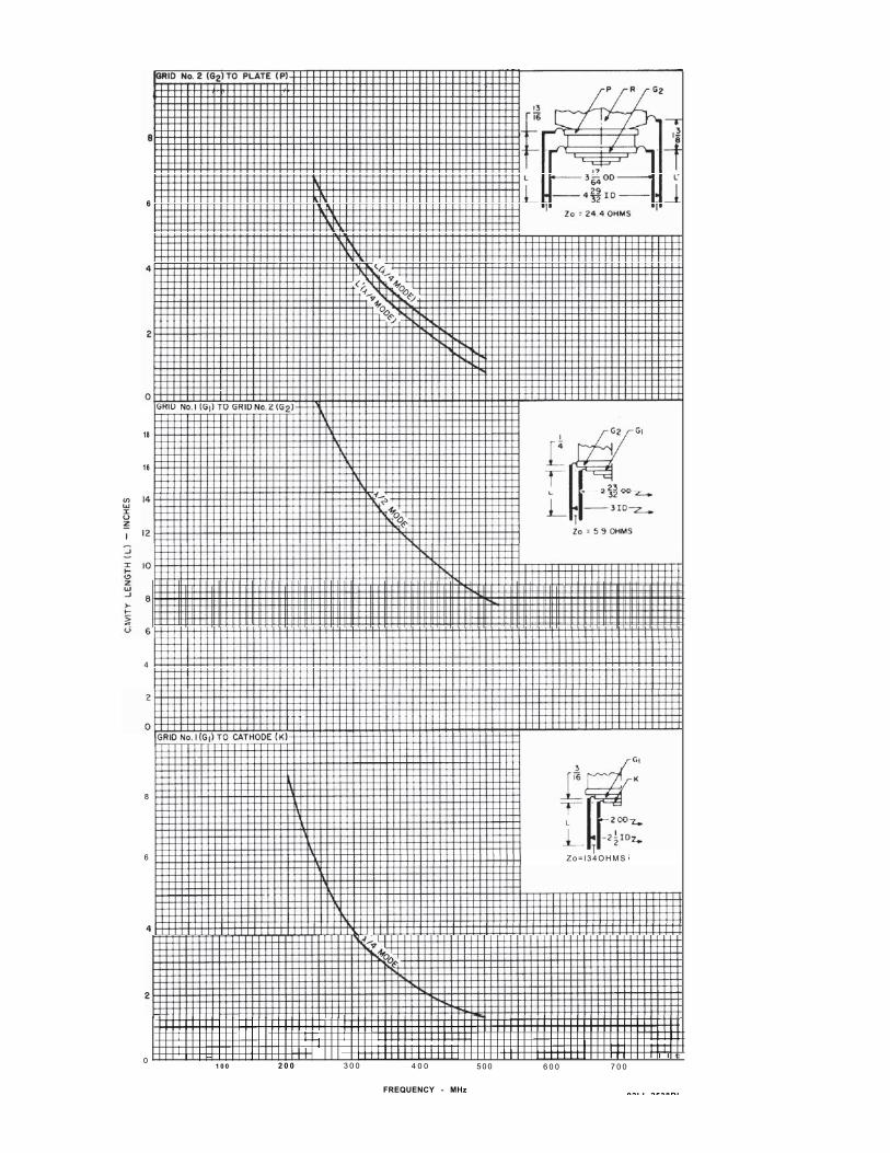
0 I -- I I I I I I t:1 0 0 2 0 0 3 0 0 4 0 0 5 0 0 6 0 0 7 0 0
FREQUENCY - MHz92LL 2538Rl
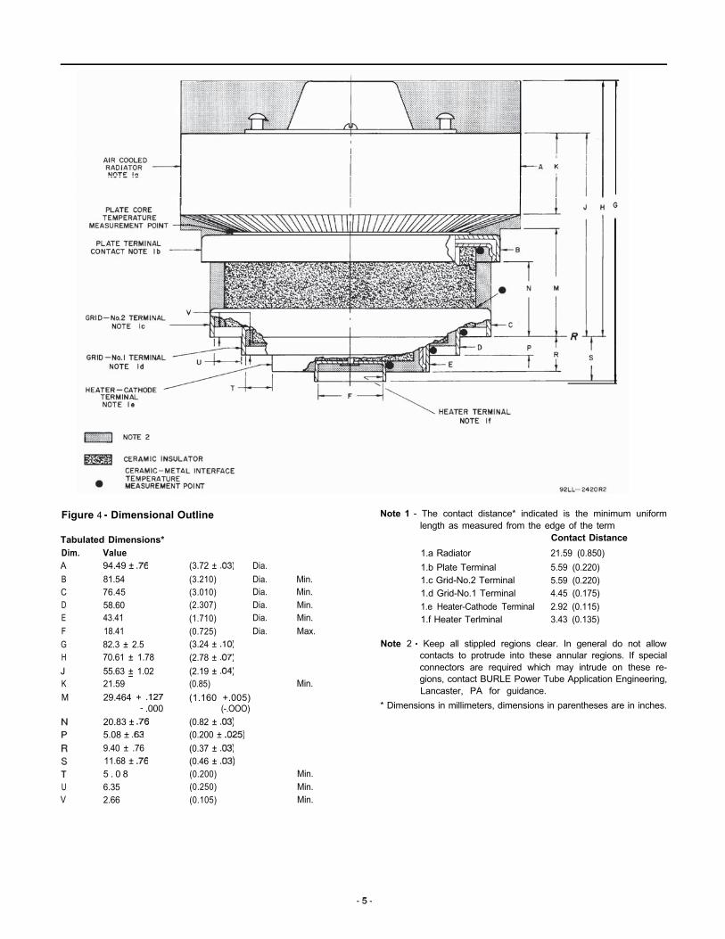
Figure 4 Dimensional Outline
Tabulated Dimensions*Dim. ValueA 94.49 ± BCDEFGHJKM
81.5476.4558.6043.4118.4182.3 ± 2.570.61 ± 1.7855.63 ± 1.0221.5929.464 +
.00020.83 ± 5.08 ± 9.40 ± .7611.68 ± 5 . 0 8
U 6.35V 2.66
(3.72 ± Dia.(3.210) Dia.(3.010) Dia.(2.307) Dia.(1.710) Dia.(0.725) Dia.(3.24 ± (2.78 ± (2.19 ± (0.85)(1.160 +.005)
(-.OOO)(0.82 ± (0.200 ± (0.37 ± (0.46 ± (0.200)(0.250)(0.105)
Min.Min.Min.Min.Max.
Min.
Min.Min.Min.
Note 1 The contact distance* indicated is the minimum uniformlength as measured from the edge of the term
Contact Distance1.a Radiator 21.59 (0.850)1.b Plate Terminal 5.59 (0.220)1.c Grid-No.2 Terminal 5.59 (0.220)1.d Grid-No.1 Terminal 4.45 (0.175)1.e Heater-Cathode Terminal 2.92 (0.115)1.f Heater Terlminal 3.43 (0.135)
Note 2 Keep all stippled regions clear. In general do not allowcontacts to protrude into these annular regions. If specialconnectors are required which may intrude on these re-gions, contact BURLE Power Tube Application Engineering,Lancaster, PA for guidance.
* Dimensions in millimeters, dimensions in parentheses are in inches.
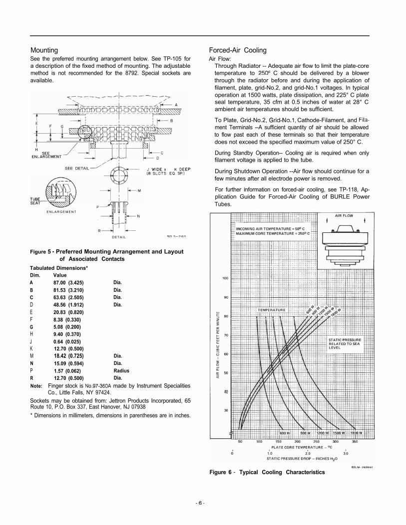
MountingSee the preferred mounting arrangement below. See TP-105 fora description of the fixed method of mounting. The adjustablemethod is not recommended for the 8792. Special sockets areavailable.
SEE DETAIL
E N L A R G E M E N T
D E T A I L
Figure 5 Preferred Mounting Arrangement and Layoutof Associated Contacts
Tabulated Dimensions*Dim. ValueA 87.00 (3.425) Dia.B 81.53 (3.210) Dia.C 63.63 (2.505) Dia.D 48.56 (1.912) Dia.E 20.83 (0.820)F 8.38 (0.330)G 5.08 (0.200)H 9.40 (0.370)J 0.64 (0.025)K 12.70 (0.500)M 18.42 (0.725) Dia.N 15.09 (0.594) Dia.P 1.57 (0.062) RadiusR 12.70 (0.500) Dia.Note: Finger stock is made by Instrument Specialities
Co., Little Falls, NY 97424.Sockets may be obtained from: Jettron Products Incorporated, 65Route 10, P.O. Box 337, East Hanover, NJ 07938* Dimensions in millimeters, dimensions in parentheses are in inches.
Forced-Air CoolingAir Flow:
Through Radiator -- Adequate air flow to limit the plate-coretemperature to C should be delivered by a blowerthrough the radiator before and during the application offilament, plate, grid-No.2, and grid-No.1 voltages. In typicaloperation at 1500 watts, plate dissipation, and 225° C plateseal temperature, 35 cfm at 0.5 inches of water at 28° Cambient air temperatures should be sufficient.
To Plate, Grid-No.2, Cathode-Filament, and ment Terminals --A sufficient quantity of air should be allowedto flow past each of these terminals so that their temperaturedoes not exceed the specified maximum value of 250° C.
During Standby Operation-- Cooling air is required when onlyfilament voltage is applied to the tube.
During Shutdown Operation --Air flow should continue for afew minutes after all electrode power is removed.
For further information on forced-air cooling, see TP-118, Ap-plication Guide for Forced-Air Cooling of BURLE PowerTubes.
Figure 6 Typical Cooling Characteristics