line distance protection psl 6602u product guide - abb ltd · 4cae000366 line distance protection...
TRANSCRIPT
—
Line distance protection PSL 6602UProduct guide

4CAE000366
Line distance protection PSL 6602U
Product version: V1.00 Issued: May 2017
Revision: -
ABB 1
Contents 1. Application ....................................................................................................................................................... 2 2. Available functions ........................................................................................................................................... 8 3. Starting component ........................................................................................................................................ 11 4. Pilot protection ................................................................................................................................................ 11 5. Distance protection ........................................................................................................................................ 12 6. Power swing blocking .................................................................................................................................... 15 7. Zero-sequence protection .............................................................................................................................. 15 8. Phase selection closing ................................................................................................................................. 16 9. Fuse failure protection ................................................................................................................................... 16 10. Pole discordance protection ....................................................................................................................... 16 11. Reclosing ................................................................................................................................................... 16 12. Voltage circuit monitoring ........................................................................................................................... 17 13. Current circuit monitoring ........................................................................................................................... 18 14. Monitoring the location of circuit-breaker ................................................................................................... 18 15. Controlling and measuring function ............................................................................................................ 18 16. Station level communication ...................................................................................................................... 19 17. Clock synchronization ................................................................................................................................ 19 18. Other functions .......................................................................................................................................... 19 19. Inter-station communication ....................................................................................................................... 20 20. Hardware description ................................................................................................................................. 21 21. IED dimensions .......................................................................................................................................... 22 22. Wiring diagram ........................................................................................................................................... 23 23. Technical data ............................................................................................................................................ 31 24. Ordering ..................................................................................................................................................... 43

4CAE000366
Line distance protection PSL 6602U
Product version: V1.00 Issued: May 2017
Revision: -
ABB 2
1. Application
PSL 6602U is designed for line distance protection of overhead lines and cables in the 220kV and higher directly grounding grid. It can be used for double-circuit lines, heavy load lines, weak infeed lines, short lines and long lines, and supports single circuit breaker and double circuit breaker configurations, with single-phase tripping and three-phase tripping.
PSL 6602U features distance protection, which is capable of quickly tripping the whole line, while having low requirements on inter-station communication. The three zone distance protection applies flexibly to all kinds of overhead lines and features a quadrilateral characteristic with load restriction, capable of covering extremely high transition resistance, while avoiding both steady state and transient state overreach. It is equipped with a power swing blocking function.
It has single- and three-phase reclosing functionality and switch onto fault protection, and reclosing is possible with a synchronization function.
Pilot communication supports communication through carrier channel or optical fiber, and both G.703 and G.703E1 protocols.
The device can record up to 1000 event records for convenient event analysis. With a complete self-supervision function, the health status of the device can be monitored.
Time synchronization is available, including PPS, PPM, IRIG-B and SNTP.
PSL 6602U supports the IEC 61850-8-1 MMS communication protocol.
The device can apply several wiring configurations:
Single circuit breaker wiring at both local and
remote sides, phase segregated tripping, voltage on
the line VT (A11)
Single circuit breaker wiring at both local and
remote sides, phase segregated tripping, voltage on
the busbar VT (A12)
Double circuit breaker wiring at local and remote
sides, phase segregated tripping (A2)

4CAE000366
Line distance protection PSL 6602U
Product version: V1.00 Issued: May 2017
Revision: -
ABB 3
Single circuit breaker wiring at local and remote sides, single-phase tripping, voltage on the line.
QB1 QB2
QA1
94
QB9
QC9
1 0
PTRC
79 0 1
RREC
25
RSYN
SC/VC
PSL 6602U – Single Breaker with phase segregated tripping and Line PT
MET UN
MMXU
21 Z <
PDIS
68 Zpsb
RPSB
67N
PTOC
85-67
PSCH
85-21
PSCH
51N
PTOC
51-VT
PTOC
51N-VT
PTOC
50SOTF
PSOF
MET
MMXU
I FL
RFLO
FL DR
RDRE
DR
50PD
RPLD
MET
MMXU
U
WA1
WA2
Bus-VT
Line-CT
Line-VT
VoltageSwitch
Figure 1: A11 Configuration diagram

4CAE000366
Line distance protection PSL 6602U
Product version: V1.00 Issued: May 2017
Revision: -
ABB 4
Single circuit breaker wiring at local and remote sides, single phase tripping, voltage on the busbar.
QB1 QB2
QA1
94
QB9
QC9
1 0
PTRC
79 0 1
RREC
25
RSYN
SC/VC
PSL 6602U – Single Breaker with phase segregated tripping and Busbar PT
MET UN
MMXU
21 Z <
PDIS
68 Zpsb
RPSB
67N
PTOC
85-67
PSCH
85-21
PSCH
51N
PTOC
51-VT
PTOC
51N-VT
PTOC
50SOTF
PSOF
MET
MMXU
I FL
RFLO
FL DR
RDRE
DR
50PD
RPLD
MET
MMXU
U
WA1
WA2
Bus-VT
Line-CT
Line-VT
VoltageSwitch
Figure 2: A12 Configuration diagram

4CAE000366
Line distance protection PSL 6602U
Product version: V1.00 Issued: May 2017
Revision: -
ABB 5
Single circuit breaker wiring at local and remote sides, single-phase tripping.
QB1
WA1_QA1
94 1 0
PTRC
PSL 6602U – Dual Breaker with phase segregated tripping
MET I
MMXU
21 Z <
PDIS
68 Zpsb
RPSB
67N
PTOC
85-67
PSCH
85-21
PSCH
51N
PTOC
51-VT
PTOC
51N-VT
PTOC
FL
RFLO
FL DR
RDRE
DR
MET
MMXU
U
WA1
WA2
TIE-CT
WA1-CT
Line-VT
WA1_QB6
QB61
TIE_QA1
QB62
QB2
WA2_QA1
WA2-QB6
LINE1_QB9
LINE2_QB9
Σ
Figure 3: A2 Configuration diagram
4CAE000366
Line distance protection PSL 6602U
Product version: V1.00 Issued: May 2017
Revision: -
ABB 6
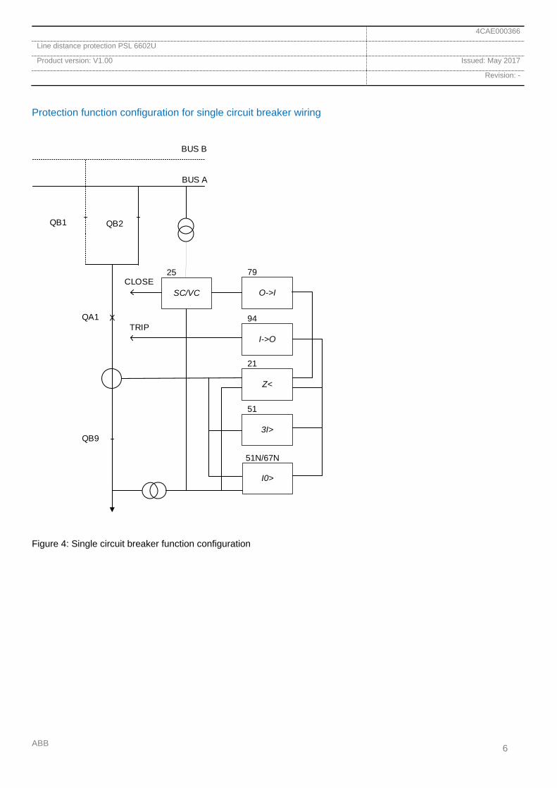
Protection function configuration for single circuit breaker wiring
QB1 QB2
QA1
QB9
BUS B
BUS A
SC/VC
25
O->I
79
I->O
94
Z<
21
3I>
51
I0>
51N/67N
CLOSE
TRIPX
Figure 4: Single circuit breaker function configuration
4CAE000366
Line distance protection PSL 6602U
Product version: V1.00 Issued: May 2017
Revision: -
ABB 7
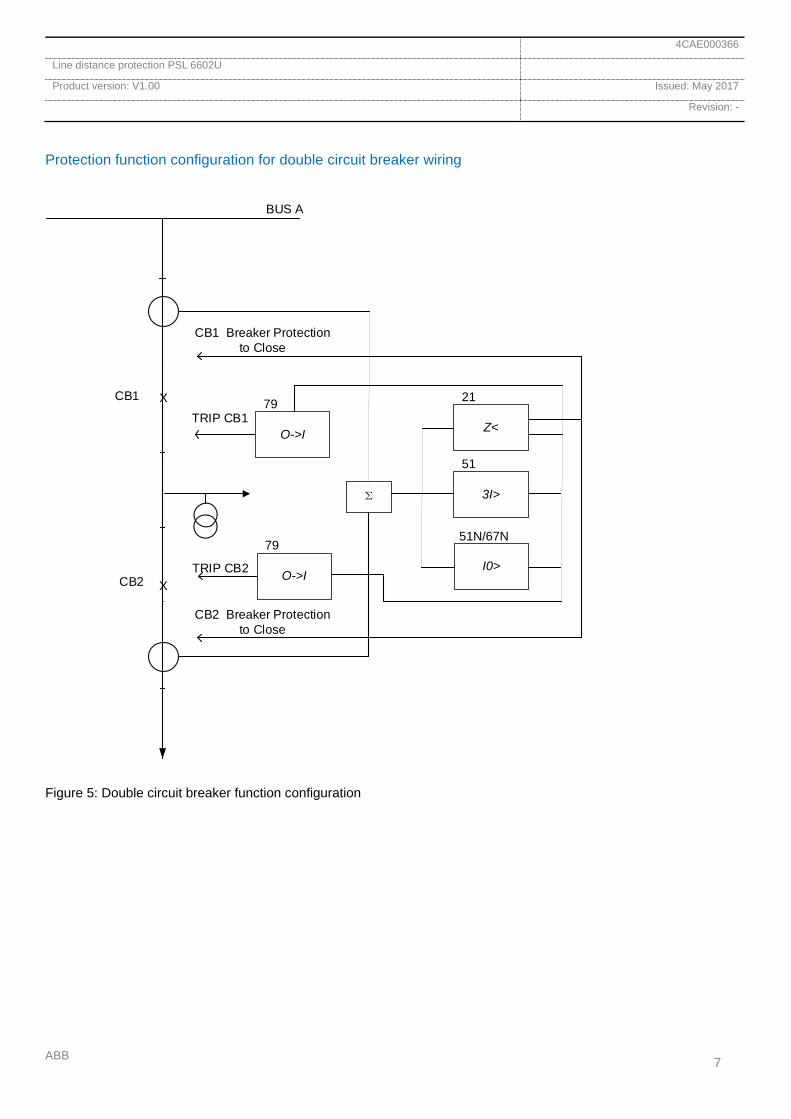
Protection function configuration for double circuit breaker wiring
CB1
BUS A
O->I
79
Z<
21
3I>
51
I0>
51N/67N
TRIP CB2
X
XCB2 O->I
79
TRIP CB1
Σ
CB2 Breaker Protection to Close
CB1 Breaker Protection to Close
Figure 5: Double circuit breaker function configuration
4CAE000366
Line distance protection PSL 6602U
Product version: V1.00 Issued: May 2017
Revision: -
ABB 8
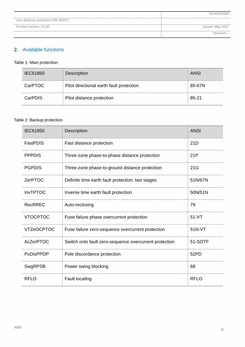
2. Available functions
Table 1: Main protection
IEC61850 Description ANSI
CarPTOC Pilot directional earth fault protection 85-67N
CarPDIS Pilot distance protection 85-21
Table 2: Backup protection
IEC61850 Description ANSI
FastPDIS Fast distance protection 21D
PPPDIS Three-zone phase-to-phase distance protection 21P
PGPDIS Three-zone phase-to-ground distance protection 21G
ZerPTOC Definite time earth fault protection, two stages 51N/67N
InvTPTOC Inverse time earth fault protection 50N/51N
RecRREC Auto-reclosing 79
VTOCPTOC Fuse failure phase overcurrent protection 51-VT
VTZeOCPTOC Fuse failure zero-sequence overcurrent protection 51N-VT
AcZerPTOC Switch onto fault zero-sequence overcurrent protection 51-SOTF
PoDisPPDP Pole discordance protection 52PD
SwgRPSB Power swing blocking 68
RFLO Fault locating RFLO

4CAE000366
Line distance protection PSL 6602U
Product version: V1.00 Issued: May 2017
Revision: -
ABB 9
Table 3: Controlling and monitoring functions
IEC61850 Description ANSI
LinMMXU Sampling and monitoring voltage, current channel
BinInGGIO Sampling and monitoring binary signals
WarGGIO Relay operation warn
DevAlmGGIO IED alarm operation
LinPTRC Tripping circuit breaker for fault isolation
EvtGGIO Protecting general event, recording and saving start reason,
name, time stamp, etc
Fuse failure supervision
Current circuit supervision
CarPSCH Pilot communication channel monitoring
IRIG-B clock synchronizing monitoring
SNTP clock synchronizing monitoring
IEC60870-5-103 communication monitoring
IEC 61850 communication monitoring
4CAE000366
Line distance protection PSL 6602U
Product version: V1.00 Issued: May 2017
Revision: -
ABB 10
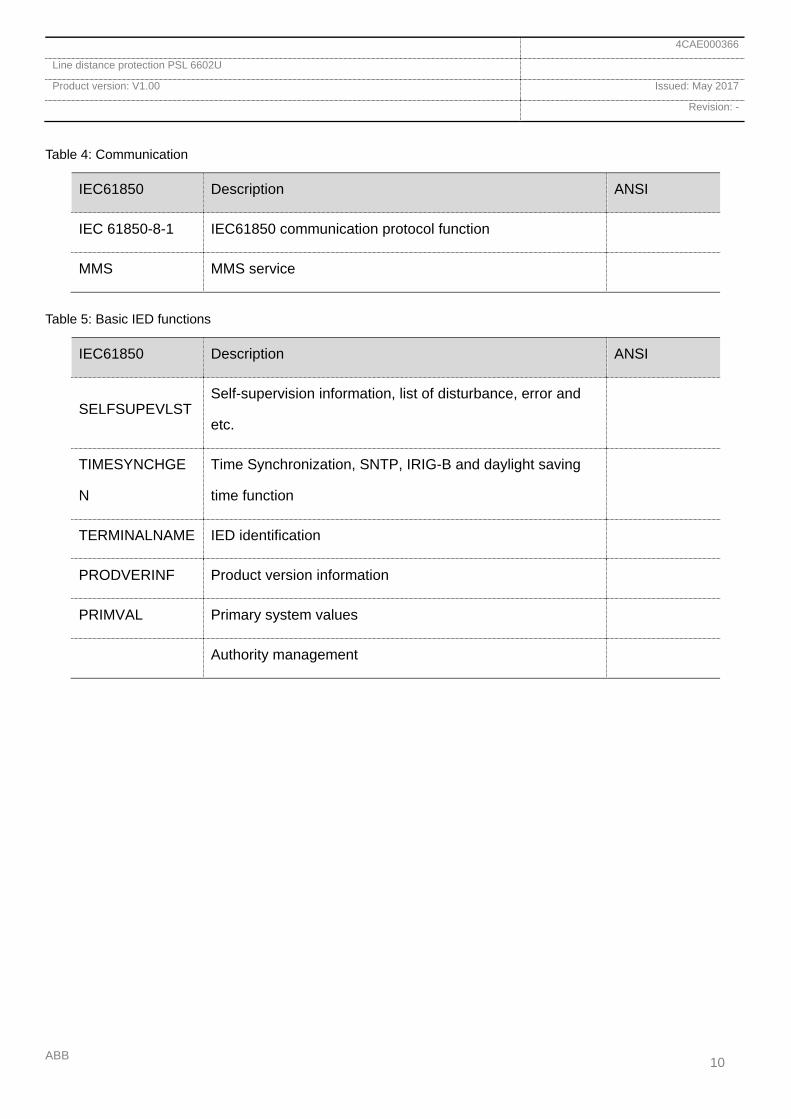
Table 4: Communication
IEC61850 Description ANSI
IEC 61850-8-1 IEC61850 communication protocol function
MMS MMS service
Table 5: Basic IED functions
IEC61850 Description ANSI
SELFSUPEVLST Self-supervision information, list of disturbance, error and
etc.
TIMESYNCHGE
N
Time Synchronization, SNTP, IRIG-B and daylight saving
time function
TERMINALNAME IED identification
PRODVERINF Product version information
PRIMVAL Primary system values
Authority management

4CAE000366
Line distance protection PSL 6602U
Product version: V1.00 Issued: May 2017
Revision: -
ABB 11
3. Starting component
Because the protection starting component is used to start the disturbance recording function and to turn on the power supply used by the coil of tripping relay, it's necessary for the starting component to start reliably under any operation circumstances.
The starting component consists of the following elements:
Delta current starting component
The delta current starting component has high sensitivity and applies to imbalanced components during normal operation and during power swing.
Zero-sequence overcurrent starting component
In case the delta current starting component doesn’t operate, for example during high resistance faults, a zero-sequence overcurrent starting component will trigger for earth faults.
Static-stability break starting component
This element is used to detect power swing caused by static-stability disruption in the system under normal conditions. When the function of voltage transformer fuse failure or power swing blocking is disabled, this component is disabled automatically.
Weak-feed starting component
The weak-feed starting component has high sensitivity of detecting faults either when a high impedance ground fault is detected or under weak-feed operation.
TWJ starting component
The TWJ starting component is responsible for starting the reclosing function under unwanted tripping of the circuit breaker.
4. Pilot protection
The direction components of the pilot protection are composed of the directional impedance component and the directional zero-sequence component. The reverse direction takes priority when these components work together, which improves the safety. The directional pilot protection can protect the device from different types of faults, including incomplete phase fault.
Directional impedance component
The directional components consist of three phase-to-phase loops: ZAB, ZBC, ZCA, and three phase-to-ground loops: ZA, ZB, ZC. The direction of impedance element for each circuit is indicated to be forward or reverse. The directional element is always positive sequence. Besides, there is a release power swing blocking component.
ZDϕZDR
ZDZ
Direction
X
R-25°
45°
ZDZ25.1
Impedance characteristic
Figure 6: Pilot impedance characteristic
The impedance characteristic is shown in Figure 6, which consists of an impedance quadrilateral characteristic and directional component.
Directional zero-sequence current component
The directional zero-sequence component is configured with forward and reverse components. The voltage threshold are fixed value and floating value. The component provides zero-sequence voltage compensation function. The function can operate correctly at low zero-sequence impedance with zero-sequence voltage lower than 0.5V.
4CAE000366
Line distance protection PSL 6602U
Product version: V1.00 Issued: May 2017
Revision: -
ABB 12
Line communication channel
The pilot protection can be connected to a variety of communication devices, such as carrier channel (private or multiplex), optical fiber channel and microwave channel.
PSL 6602U pilot protection adapts to channels by selecting enabled or blocked mode based on protection operation mode. Generally, dedicated blocked mode is for dedicated trans receiver while enabled mode is for carrier and multiplex optical fiber channel.
Current reversal
To avoid maloperation caused by current reversal during external fault clearance, a time delay is applied during current reversal. The advantage of this is when a line fault happens during protection start caused by open phase operation or disturbance with current reversal conditions, the pilot protection operation time delay will not be extended.
Weak-end infeed
The definition of weak-end side: the weak source end or no power supply end of a line; when internal fault happens, if none of the forward/reverse directional components on one end of the pilot protection are sensitive enough, then this is the weak-end infeed side.
When internal fault happens, the weak-end infeed function issues a signal that commands the remote side to operate, to rapidly trip the remote protection. That is, in dedicated blocking mode, weak-source side can quickly stop sending message; in enabled mode, weak-source side can quickly send the enabling message.
5. Distance protection
Fast distance protection
The device is equipped with two fast distance functions with different principles. When any of them operates, the fast distance protection is tripped. The fast distance function can quickly clear disturbances on the near end of a long line.
Waveform comparison-based fast distance
protection
For protection functions based on fundamental components, static state acyclic and harmonic components of the fault are filtered via an algorithm or filter. The longer the data window is, the better the filtering effect is, but the slower the operation speed becomes. The size and characteristic of transient harmonics differ a lot in various systems. In selecting the right algorithm, the measurement accuracy in the most demanding condition needs to be satisfied, which implies it is difficult to greatly accelerate the protection operation speed.
Fast distance protection of the device adopts a fast algorithm based on a waveform recognition principle, which can estimate the real-time noise level from the fault current waveform and adjust the operation threshold automatically, greatly accelerating the operation speed.
Sudden change distance protection
Per the superimposed principle of electric circuit theory, the short-circuit disturbance status can be split into pre-fault and post-fault status. The sudden change distance relay directly reflects the amplitude variation between these 2 states.

4CAE000366
Line distance protection PSL 6602U
Product version: V1.00 Issued: May 2017
Revision: -
ABB 13
Distance protection
Per circuit configuration, distance protection consists of three phase-to-phase loops: Zbc, Zca, Zab, and three phase-to-ground loops: Za, Zb, Zc. Besides the three available zones available in the distance protection, each circuit has an auxiliary impedance component, thus resulting in a total of 24 measurement loops.
In all-phase operation, all 24 loops are enabled simultaneously; in open phase operation, only the measurement loops of healthy phases are enabled. For example, only the Zbc, Zb and Zc loops are enabled when phase A is opened.
Phase-to-phase and phase-to-ground measurement loops mainly consist of an offset impedance component, a phase selector and a positive-sequence directional component, while the phase-to-ground distance relay also has zero-sequence component.
Offset impedance component
ZDΦZDΦ
ZDRR’
X
X’
R
IZDZ
IIZDZ
IIIZDZ
Figure 7: Offset impedance component characteristic
The offset impedance component is an impedance relay with a quadrilateral (polygon) characteristic, whose operation range is decided by the distance
impedance setting ZDZ , the resistance setting ZDR and
the line positive-sequence impedance angle ZDΦ . The
resistance deviation threshold and reactance deviation threshold are formed automatically by the protection.
Non directional impedance auxiliary component
ZDΦZDΦ
ZDR
X
R
IIIZDZ
Figure 8: All-impedance auxiliary component
The operation range of the phase selector component with its non-directional characteristic is decided by the
impedance setting IIIZDZ , the distance resistance
setting ZDR and the line positive-sequence impedance
angle on the distance zone III ZDΦ .
The non-directional impedance auxiliary component is an auxiliary component used for detecting static-stability break, faulty phase selection and as a reset element, instead of being a zone criterion of protection.
Positive-sequence directional component
The positive-sequence directional component compares phases by checking positive-sequence voltage and circuit current. This ensures correct direction when an asymmetrical fault happens. However, when a symmetrical three phase fault happens, with a positive-sequence voltage of zero, the fault direction cannot be shown correctly. Thus, when all three phase voltages are low, memory voltage is used instead, fixing the direction and comparing phases with positive-sequence voltage after voltage recovery.

4CAE000366
Line distance protection PSL 6602U
Product version: V1.00 Issued: May 2017
Revision: -
ABB 14
Zero-sequence reactance component
During a phase to ground or double phase to ground fault on parallel lines, the phase to ground loop of the distance protection may cause overreach. To avoid this overreach, a zero-sequence reactance component is added to the phase-to-ground distance protection zone I and II.
Phase-to-ground distance
ZDΦZDΦ
ZDRR’
X
X’
R
IZDZ
IIZDZ
12°
25°
45°
F1 X0
F1
Figure 9: Phase-to-ground zone I and II characteristic
ZDΦZDΦ
ZDRR’
X
X’
R
IIIZDZ
25°
45°
F1
F1
Figure 10: Phase-to-ground zone III characteristic
The operation characteristic of the phase-to-ground zone I and II is shown in figure 8. The offset impedance zone I and II, the positive-sequence directional component F1 (area above dotted line in F1), and the zero-sequence reactance component X0 (area under dotted line X0 in the figure) compose jointly the operation area of the phase-to-ground zone I and II.
The operation characteristic of the phase-to-ground distance zone III is shown in figure 9.
Phase-to-phase distance
ZDΦZDΦ
ZDRR’
X
X’
R
IZDZ
IIZDZ
24°
25°
45°
F1
F1
Figure 11: Phase-to-phase distance characteristic, zone I, II
The operation characteristic of the phase-to-phase distance zone I and II is shown in figure 10. The phase-to-phase offset impedance zone I and II and the positive-sequence directional component F1 (area above dotted line in F1) jointly compose the operation area of the phase-to-phase distance zone I and II. The operation characteristic of the phase-to-phase distance zone III is like that of the phase-to-ground distance zone III, like shown in Figure 9.
Switch onto fault line protection
Switch onto fault protection consists of distance acceleration and zero-sequence acceleration. The acceleration pulses of both reclosing and manual closing are 200ms; acceleration function will be disabled 200ms after closing.
During auto-reclosing, the distance protection enables the acceleration impedance zone II and during manual closing the distance protection enables the acceleration impedance zone III. The closing acceleration time delay is automatically adapted to the waveform coefficient of the acceleration phase current; a short time delay for low harmonic content and a long time delay for high harmonic content.
4CAE000366
Line distance protection PSL 6602U
Product version: V1.00 Issued: May 2017
Revision: -
ABB 15
6. Power swing blocking
The power swing blocking component avoids unwanted operation and failure to operate of line distance protection under the following conditions:
No unwanted operation during power swing;
No unwanted operation during inverse fault of
power swing;
No unwanted operation during external fault of
power swing;
Reliable operation during internal fault of power
swing.
150ms after the sudden change component starts or after auxiliary zero-sequence current starts or if static-state break starts, power swing blocking is enabled. During power swing blocking, line distance and distance protection zone I and II is only enabled when the release power swing blocking component operates.
For lines where power swing never happens, power swing blocking can be disabled to accelerate the protection operation. The release power swing blocking component of the device adopts a sequence component method and swing impedance track radius detecting method; when either of them operates, the power swing blocking component is released. The former only works for asymmetrical faults and is disabled during open phase operation of line; the latter works for both all-phase and open phase operations.
Sequence component method
The distance protection is started when 0 2 1I I mI+ > .
This method starts protection according to the zero-sequence and negative-sequence components produced during asymmetrical fault. m is a reliability coefficient, which ensures no maloperation for external fault during power swing.
Swing impedance track radius detecting method
The track of the measured impedance through the impedance plane is a circle during power swing or when a fault happens through some fault resistance during power swing. The track changes from a circle to a point when a metallic fault happens. The impedance rate-of-change is internally related to the radius of the circle track. This method avoids operation during power swing by measuring the impedance track.
7. Zero-sequence protection
The device has zero-sequence overcurrent protection of two zones with a definite time limit and one zone with an inverse time limit.
Zone II and the zero-sequence inverse time protection are directional while it's optional for the zero-sequence zone III to be directional or not. When fuse failure occurs, the zero-sequence zone II protection is automatically disabled and both the zero-sequence inverse time protection and zero-sequence zone III protection become non-directional.
During open phase operation, the zero-sequence zone II protection and zero-sequence inverse time protection are disabled and only the zero-sequence zone III protection, automatically made non-directional, is kept as the backup protection for asymmetrical faults.
During reclosing acceleration, the zero-sequence zone II and III protection and zero-sequence inverse time protection are disabled and only the zero-sequence switch-onto-fault zone is enabled.
4CAE000366
Line distance protection PSL 6602U
Product version: V1.00 Issued: May 2017
Revision: -
ABB 16
8. Phase selection closing
The protection device combines a phase selector based on sudden change and sequence components. By using a composite of both currents and voltages for the sudden change phase selector, it guarantees sensitivity on the weak power side. During the transient period of a fault the sudden change phase selector is active, while the sequence component phase selector is put into use in the sub-transient and steady state period.
Current and voltage composite sudden change
phase-selector
The phase selector measures sudden changes of phase-to-phase voltage and phase-to-phase current. By comparing the acquired three composite sudden changes of phase-to-phase voltage and current, the fault loop can be determined.
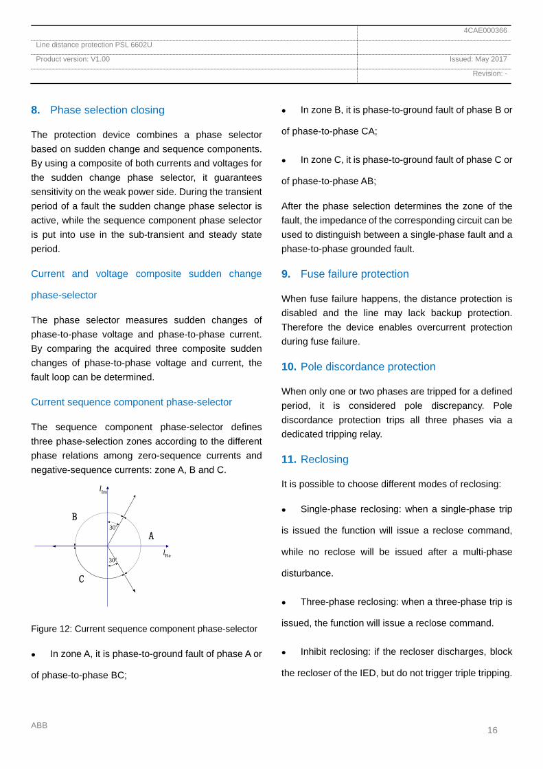
Current sequence component phase-selector
The sequence component phase-selector defines three phase-selection zones according to the different phase relations among zero-sequence currents and negative-sequence currents: zone A, B and C.
30o
30o Rel
Iml
A
C
B
Figure 12: Current sequence component phase-selector
In zone A, it is phase-to-ground fault of phase A or
of phase-to-phase BC;
In zone B, it is phase-to-ground fault of phase B or
of phase-to-phase CA;
In zone C, it is phase-to-ground fault of phase C or
of phase-to-phase AB;
After the phase selection determines the zone of the fault, the impedance of the corresponding circuit can be used to distinguish between a single-phase fault and a phase-to-phase grounded fault.
9. Fuse failure protection
When fuse failure happens, the distance protection is disabled and the line may lack backup protection. Therefore the device enables overcurrent protection during fuse failure.
10. Pole discordance protection
When only one or two phases are tripped for a defined period, it is considered pole discrepancy. Pole discordance protection trips all three phases via a dedicated tripping relay.
11. Reclosing
It is possible to choose different modes of reclosing:
Single-phase reclosing: when a single-phase trip
is issued the function will issue a reclose command,
while no reclose will be issued after a multi-phase
disturbance.
Three-phase reclosing: when a three-phase trip is
issued, the function will issue a reclose command.
Inhibit reclosing: if the recloser discharges, block
the recloser of the IED, but do not trigger triple tripping.
4CAE000366
Line distance protection PSL 6602U
Product version: V1.00 Issued: May 2017
Revision: -
ABB 17
Disable reclosing: if the recloser discharges, block
the recloser of the IED and trigger triple tripping.
Triple tripping logic will drive four pairs of normally
closed contacts. The conditions for triggering triple
tripping are:
Recloser is in three-phase reclosing mode;
Recloser is in single-phase reclosing mode and
the spring is not charged;
Recloser is disabled;
Recloser is blocked;
Recloser is inhibited or the setting is wrong;
Device is not powered on.
If any of the above conditions is fulfilled, the four pairs of contacts on the output board of the recloser will close, connecting either the protection or the BDJ (IED output) of the other protection device to the trip coil.
Auto-reclosing
There are two modes for starting auto reclosing: protection tripping order start and circuit breaker position discrepancy.
Reclosing charging and discharging
To avoid unwanted reclosing, it is valid only after CB "charging" completely. In the reclosing logic of the device, a software counter is used to simulate the charging and discharging process of the reclosing.
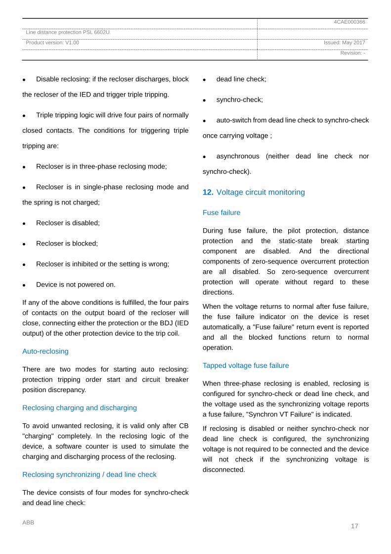
Reclosing synchronizing / dead line check
The device consists of four modes for synchro-check and dead line check:
dead line check;
synchro-check;
auto-switch from dead line check to synchro-check
once carrying voltage ;
asynchronous (neither dead line check nor
synchro-check).
12. Voltage circuit monitoring
Fuse failure
During fuse failure, the pilot protection, distance protection and the static-state break starting component are disabled. And the directional components of zero-sequence overcurrent protection are all disabled. So zero-sequence overcurrent protection will operate without regard to these directions.
When the voltage returns to normal after fuse failure, the fuse failure indicator on the device is reset automatically, a "Fuse failure" return event is reported and all the blocked functions return to normal operation.
Tapped voltage fuse failure
When three-phase reclosing is enabled, reclosing is configured for synchro-check or dead line check, and the voltage used as the synchronizing voltage reports a fuse failure, "Synchron VT Failure" is indicated.
If reclosing is disabled or neither synchro-check nor dead line check is configured, the synchronizing voltage is not required to be connected and the device will not check if the synchronizing voltage is disconnected.
4CAE000366
Line distance protection PSL 6602U
Product version: V1.00 Issued: May 2017
Revision: -
ABB 18
13. Current circuit monitoring
CT reverse phase rotation
In the first 2 hours after the device is energized, the phase sequence of AC current is checked. When a inverse phase rotation is detected, a runtime error alarm is reported, but the protection is not blocked.
CT load asymmetry
When the maximum phase-to-phase current difference is greater than 50% of the maximum phase current and the maximum phase current is greater than 25% of the rated current, a runtime error alarm is sent with a time delay, but the protection is not blocked.
CT imbalance
When the zero-sequence current 3I0 is greater than the start setting value, an alarm is sent with a time delay and the zero-sequence current starting component is blocked.
14. Monitoring the location of circuit-breaker
For single phase circuit-breakers, when the position of the three phases are different or when the circuit-breaker is at an open position but current can still be measured, an alarm is sent with a time delay.
15. Controlling and measuring function
Analog signal sampling
The analog signal monitoring function applies to sampled currents and voltages. Their amplitudes and phase-angles will be displayed on the HMI. These sampled values can be used to verify that the instrument transformers (i.e. current transformer and voltage transformer) are operating properly and connected correctly.
The IED acquires data from current and voltage values with a sampling frequency of 1200 samples per second for 50Hz. Among all channels with valid voltages / currents, the one has the minimum channel ID will be chosen as the phase angle, with the fixed angle of 0.01°.
Binary signal indication
Binary signal indication is used to acquire and monitor the connected binary input status (BI).
The status of BI channels can be checked via the HMI.
Signal indicators
LED signal indicators display the working conditions of the device.
Event recording
It's crucial to acquire fast, complete and reliable disturbance information of the primary/secondary system, such as time tagged events during a disturbance, which can be used for short-term (such as fault recovery) and long-term (function analysis) objectives. Once any new recording is triggered, the event recorder will record the cause, identification and time stamp of the operation, and then store them in non-volatile memory.
At least 1000 latest event records can be stored, which can be retrieved later via the HMI.
Disturbance reporting
Disturbance reports will be formed and saved automatically in non-volatile memory when a binary signal triggers a recording or when there are fault location results.
The disturbance report will pop up automatically on the HMI after a disturbance, and can also be manually checked.

4CAE000366
Line distance protection PSL 6602U
Product version: V1.00 Issued: May 2017
Revision: -
ABB 19
A disturbance report records the operation start time, operation type, faulty phase, fault locating, tripped phase(s), the RMS value of the fault current / voltage, and so on.
At least 1000 latest disturbance reports can be stored in non-volatile memory, which can be retrieved later via the HMI.
Disturbance recording
A disturbance record is automatically formed after the protection starts or trips. After recording, the records will be automatically saved in non-volatile memory for later analysis.
The disturbance record will record the data of the 60ms before the recording starts and at least 200ms after the recording starts.
Local signal reset
After a disturbance, latching indicators such as tripping and reclosing LEDs are available.
A local reset operation can be realized via the HMI or by pressing the reset button on the IED panel directly.
Remote signal reset
After a disturbance, latching indicators such as tripping and reclosing LED are available.
A reset operation can be controlled on the IED or via the remote master station.
16. Station level communication
IEC 61850-8-1
The IEC 61850-8-1 MMS communication protocol is supported, in which MMS applies to communication between station control level and bay level.
The MMS service supports disturbance recording retrieval in the COMTRADE format.
The device supports a maximum of 16 simultaneously connected clients.
The device is equipped with 2 completely independent Ethernet ports for the MMS service, which have exactly the same function and can be configured to different station level networks.
IEC 60870-5-103
The IEC 60870-5-103 communication protocol is supported, providing two RS-485 ports and a RJ45 TCP/IP port. The communication rate of speed of RS-485 can be set according to requirement.
17. Clock synchronization
The device supports time synchronization through PPS, PPM, IRIG-B and SNTP, with an accuracy of 1ms.
Based on Ethernet: SNTP time synchronization
With time synchronizing wiring: PPS, PPM, IRIG-
B time synchronization
Time zone selection
The device supports UTC time zone selection. After selecting the time zone, the corresponding time will be added or subtracted from the reference time: for zero zone, time shift is 0; for UTC +1...+12 zone, time shift is +1...+12 on the reference time; for UTC -1...-12 zone, time shift is -1...-12 on the reference time.
18. Other functions
Binary input oscillation and debounce filter
To decrease binary signal input jitter and short-time disturbances, whenever a binary signal changes from 0 to 1 or from 1 to 0, the device will scan its position every 0.467ms. When the new status continuously satisfies the set time requirements, the binary signal will be counted as the new status of the binary signal.
4CAE000366
Line distance protection PSL 6602U
Product version: V1.00 Issued: May 2017
Revision: -
ABB 20
When the input voltage of binary signal is greater than 70% of the rated voltage, the operation of the binary signal is considered valid, set as 1; while if it's lower than 55%, it’s considered reset, set as 0.
Internal and self-supervision event list
The internal event list responds to different internal self-supervision modules. All internal events are saved in one internal event list.
The device periodically (and when energized) completely self-supervises the hardware/software, and will issue an alarm when an error is detected.
Human-machine interface (HMI)
The device includes a 5.7-inch color LCD touch screen, with a resolution of 320*240.
Figure 13: Color LCD
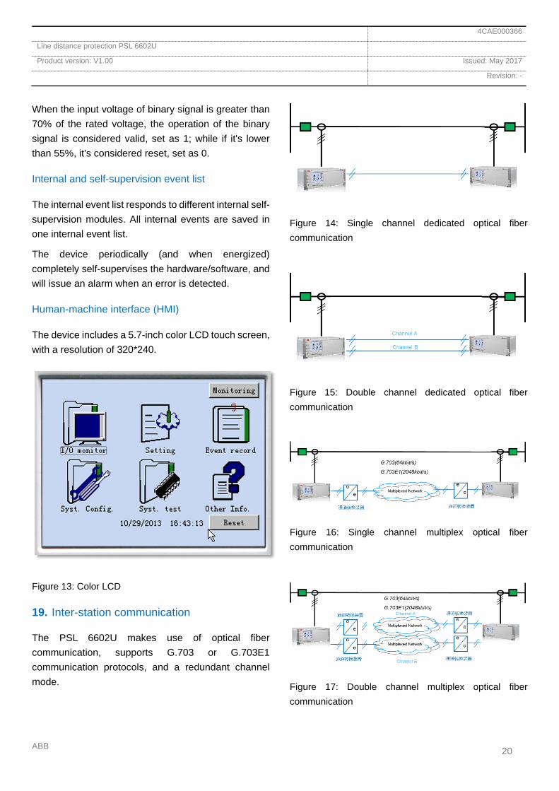
19. Inter-station communication
The PSL 6602U makes use of optical fiber communication, supports G.703 or G.703E1 communication protocols, and a redundant channel mode.
Figure 14: Single channel dedicated optical fiber communication
Figure 15: Double channel dedicated optical fiber communication
Figure 16: Single channel multiplex optical fiber communication
Figure 17: Double channel multiplex optical fiber communication

4CAE000366
Line distance protection PSL 6602U
Product version: V1.00 Issued: May 2017
Revision: -
ABB 21
Figure 18: Redundant channel of dedicated and multiplex optical fiber
20. Hardware description
Analog input module
The IED analog inputs connect the CT and VT secondary output current and voltage to the protection device, The CT secondary rated values are either 1A or 5A.
DC power supply module
The DC power supply module provides the required direct currents at different voltage levels required for normal IED operation. The power supply has an input voltage of either 110V or 220V DC.
Binary input module
The binary input module samples external binary output signals at 110V or 220V DC.
Binary output module
Potential free signals are made available by the device, for such as IED tripping and IED signals.
CPU module
The CPU module is the core component of the device, including the A/D circuit and the protection logic computation. In addition, the CPU module includes the optical fiber line communication port and provides an independent test port.
The protection device uses two CPU modules to improve the device's reliability. One of the CPU modules is used to start the output relay power supply while the other drives the tripping output; both have independent A/D sampling circuits and logic processing circuits.
HMI module
The HMI module is a human-machine dialog module, processing station level communication, the LCD interface display and the time synchronization function.
4CAE000366
Line distance protection PSL 6602U
Product version: V1.00 Issued: May 2017
Revision: -
ABB 22
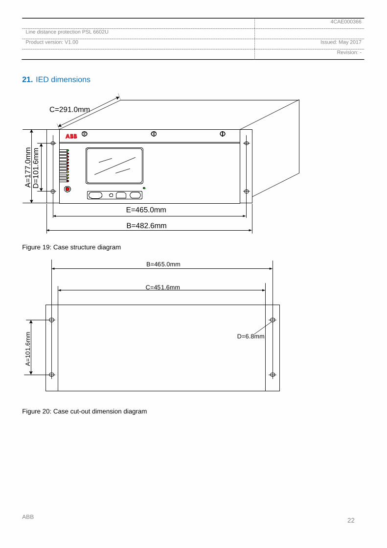
21. IED dimensions
C=291.0mm
D=1
01.6
mm
A=1
77.0
mm
E=465.0mm
B=482.6mm
Figure 19: Case structure diagram
B=465.0mm
C=451.6mm
A=1
01.6
mm D=6.8mm
Figure 20: Case cut-out dimension diagram

4CAE000366
Line distance protection PSL 6602U
Product version: V1.00 Issued: May 2017
Revision: -
ABB 23
22. Wiring diagram
General IED wiring diagram
X1
Rx
t x
Rx
t x
X2 X3 X4 X5 X6 X7 X8 X9 X10 X11 X12 X13 X14
Figure 21: IED back panel layout diagram (dotted line for optional module)
Table 6: IED back panel module list
Slot No. Module code Module type Note
X1 AC Transformer input module Analog input
X2 CPU CPU
X3 CPU CPU
X4 MMI Human interface module
X5 DI Binary input module
X6 DI Binary input module
X7 SIGNAL Binary output for signal module
X8 TRIPA Binary output for tripping module
X9 TRIPA Binary output for tripping module
X10 TRIPB Binary output for tripping module With NC contacts
X11 TRIPA Binary output for tripping module
X12 NULL /
X13 LOGIC Binary input and output module Option
X14 POWER Power supply module

4CAE000366
Line distance protection PSL 6602U
Product version: V1.00 Issued: May 2017
Revision: -
ABB 24
Power module wiring diagram
INTERNAL FAILX141
3
X14
24
Power Fail 1
Power Fail 2
DC
X14
8 10Power Input
Power output
+ + + - + -Protective earth must be
connected
X14
5 6 X14
12DC24V Output
Power Supply input
DC 220VDC 110V
Power supply module
Figure 22: Power module wiring diagram

4CAE000366
Line distance protection PSL 6602U
Product version: V1.00 Issued: May 2017
Revision: -
ABB 25
Analog input module wiring diagram
Transformer input module (TRM)
configuration
LINE_CT_IA
LINE_CT_IB
LINE_CT_IC
LINE_VT_UA
LINE_VT_UB
LINE_VT_UC
WA_VT_UX
Ch1 (I)
Ch2 (I)
Ch3 (I)
Ch4 (I)
Ch5 (U)
Ch6 (U)
Ch7 (U)
X11
*LINE_CT_I0
Ch8 (U)
23
45
67
8
9
10
11
12
13
16
ANALOG INPUT
RATED VOLTAGE 100V
RATED CURRENT 1A/5A
Figure 23: Analog input module wiring diagram

4CAE000366
Line distance protection PSL 6602U
Product version: V1.00 Issued: May 2017
Revision: -
ABB 26
Binary input module wiring diagram
BINARY INPUT MODULE (BIM)
Pilot protection enable
X5
NULL
NULL
NULL
NULL
NULL
NULL
AR disabled
Channel test button
Other protection operation
Receive A/receive
Receive B
NULL
Receive C
unlocking
Channel Alarm
NULL
NULL
NULL
BI1
BI2
BI3
BI4
BI5
BI6
BI7
BI8
BI9
BI10
BI11
BI12
BI13
BI14
BI15
BI16
BI17
BI18
BI19
BI20
X5/X6
1
2
3
4
5
6
7
8
9
1011
12
1415
16
17
18
19
20
2122
+
+
+
+
+
+
+
+
+
+
+
+
+
+
+
+
+
+
+
+-
BI VOLTAGE
DC 110V/220V
CONFIGURATION
LINE_QA1_POSITION_A
LINE_QA1_POSITION_B
LINE_QA1_POSITION_C
Other block AR
NULL
NULL
NULL
NULL
NULL
NULL
NULL
NULL
NULL
NULL
NULL
NULL
NULL
NULL
NULL
NULL
X6
NULL
NULL
Figure 24: Binary input module wiring diagram
4CAE000366
Line distance protection PSL 6602U
Product version: V1.00 Issued: May 2017
Revision: -
ABB 27
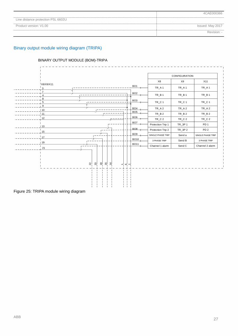
Binary output module wiring diagram (TRIPA)
BINARY OUTPUT MODULE (BOM)-TRIPA
TR_A 1
X8X8/X9/X11374
58
2
CONFIGURATION
X9
TR_B 1
TR_C 1
TR_A 2
TR_B 2
TR_C 2
Protection Trip 1
Protection Trip 2
SINGLE PHASE TRIP
3 PHASE TRIP
Channel 1 alarm
TR_A 1
TR_B 1
TR_C 1
TR_A 2
TR_B 2
TR_C 2
TR_3P 1
TR_3P 2
Send a
Send B
Send C
X11
TR_A 1
TR_B 1
TR_C 1
TR_A 2
TR_B 2
TR_C 2
PD 1
PD 2
SINGLE PHASE TRIP
3 PHASE TRIP
Channel 2 alarm
9
6
1011
121
13
15
17
19
21
1416182022BO1
BO2
BO3
BO4BO5
BO6
BO7
BO8
BO9
BO10
BO11
Figure 25: TRIPA module wiring diagram

4CAE000366
Line distance protection PSL 6602U
Product version: V1.00 Issued: May 2017
Revision: -
ABB 28
Binary output module wiring diagram (TRIPB)
BINARY OUTPUT MODULE (BOM)-TRIPB
CLOSE 1
X10X10374
58
2
CONFIGURATION
NULL
NULL
CLOSE 2
NULL
NULL
CLOSE SIGNAL
SHUNT TRIPPING
SHUNT TRIPPING
SHUNT TRIPPING
SHUNT TRIPPING
9
6
1011
12
1
13
15
17
19
21
1416182022
BO1
BO2
BO3
BO4BO5
BO6
BO7
BO8
BO9
BO10
BO11
Figure 26: TRIPB module wiring diagram
4CAE000366
Line distance protection PSL 6602U
Product version: V1.00 Issued: May 2017
Revision: -
ABB 29
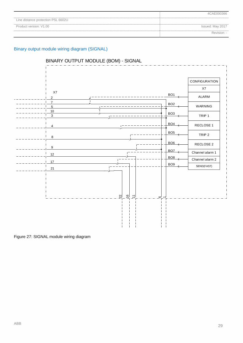
Binary output module wiring diagram (SIGNAL)
BINARY OUTPUT MODULE (BOM) - SIGNAL
ALARM
X7X7
275
310
1
CONFIGURATION
WARNING
TRIP 1
Channel alarm 1
SEND(FAST)
6
4
8
9
12
17
21
111622
BO1
BO2
BO3
BO4
BO5
BO6
BO7
BO8
BO9
RECLOSE 1
TRIP 2
RECLOSE 2
Channel alarm 2
Figure 27: SIGNAL module wiring diagram

4CAE000366
Line distance protection PSL 6602U
Product version: V1.00 Issued: May 2017
Revision: -
ABB 30
Human-machine dialog module wiring diagram (HMI)
SYN
HMI MODULE
GPS+
X4
GPS-
GPS_GND
RESET
REMOTE CONTROL ENABLE
PRINT LATEST EVEN
REPAIR
RS-485 port
1
RS-485 +
RS-485 -
RS-485 GND
RS-485 port
2
RS-485 +
RS-485 -
RS-485 GND
BI1
BI2
BI3
BI4
X4
1
3
5
6
8
9
10
13
14
15
16
18
17
2
GPS+
+
+
+
+
CONFIGURATION
GPS-
GPS_GND
RS485-EIA -1
RS485-EIA -2
DC24v -
ETHERNET 1
ETHERNET 2
ETHERNET 3
RS232-PRINT
Figure 28: HMI module wiring diagram

4CAE000366
Line distance protection PSL 6602U
Product version: V1.00 Issued: May 2017
Revision: -
ABB 31
23. Technical data
Analog input
Table 7: Rated value and limited value of IED AC module
Project Rated value Nominal value
Alternating current
Overload capability
Burden
Ir=1 or 5A
4 times the rated current, continuous operation
10 times the rated current, 16s permitted
10050 times the rated current, 1s permitted
≤ 0.5VA/phase (Ir=5A)
≤ 0.3VA/phase (Ir=1A)
(0.04…40)Ir
Alternating voltage
Overload capability
Burden
Phase voltage rated100 / 3 V
Synchronizing voltage rated100 / 3 V
1.4 times the rated voltage, continuous operation
2 times the rated voltage, 10s permitted
≤ 0.5VA/phase (rated voltage)
Phase voltage: 0.2 V…70V
Synchronizing voltage: 0.3 V…120V
Frequency 50Hz/60Hz ±5%

4CAE000366
Line distance protection PSL 6602U
Product version: V1.00 Issued: May 2017
Revision: -
ABB 32
Auxiliary DC power supply
Table 8: Rated value and limited value of IED power module
Project Rated value Nominal range
Auxiliary DC voltage
Un =DC 110V
Un =DC 220V
(80%...115%)Un
Burden
Operating: ≤ 40W
Tripping: ≤ 50W
Auxiliary DC power supply ripple coefficient
≤ 5%
Maximum de-energized time for auxiliary DC voltage without IED restart
100ms, U auxiliary
Binary input
Table 9: Binary input module (BIM)
Project Rated value Nominal value
Binary signal 20
Alternating voltage
Un=DC 110V
Un=DC 220V
Reliable operating voltage 154V DC
77V DC
Un=DC 220V
Un=DC 110V
Reliable non-operating voltage 121V DC
60.5V DC
Un=DC 220V
Un=DC 110V
Burden <0.3mW
<0.2mW
DC 220V
DC 110V
Binary signal resolution ≤1ms

4CAE000366
Line distance protection PSL 6602U
Product version: V1.00 Issued: May 2017
Revision: -
ABB 33
Binary output
Table 10: Binary output module (BOM)
Project Trip and signal relays
Binary signal 14
Maximum system voltage 250V AC, DC
Withstand voltage between contacts 1000V RMS for 1min
Between contact and coil 2000V RMS for 1min
Contact maximum permitted voltage 380V AC, 125V DC
Contact maximum permitted current 5A continuous
30A last for 200ms
AC rated capacity for disconnection (resistance load) 250V 8A single contact relay
250V 5A double contact relay
DC rated capacity for disconnection (resistance load) 0.15A, C220V, at L/R≤40ms
0.30A, C110V, at L/R≤40ms
Burden 300mW
Operation time Max 10ms
Reset time Max 5ms
Ambient conditions and test
Table 11: Ambient conditions
Parameter Reference value
Operation temperature range -25...+55ºC (continuous)
Short-time service temperature range -25…+70ºC(<16h)
Relative humidity <93%, no moisture condensation
Atmospheric pressure 66...110 kPa
Altitude Maximum 4000m
Transport and storage temperature range -25...+70ºC

4CAE000366
Line distance protection PSL 6602U
Product version: V1.00 Issued: May 2017
Revision: -
ABB 34
Table 12: Ambient test
Description Type test Reference standard
Cold test Operation 96 hours at -25ºC
96 hours at -40ºC
IEC 60068-2-1/ANSI
C37.90-2006 storage
Dry heat test Operation 16 hours at +55ºC
96 hours at +70ºC
IEC 60068-2-2/ANSI
C37.90-2006 Storage
Wet heat test Operation 240 hours at +40ºC, humidity 93%
6 loops at +25 … +55ºC, humidity 93 ... 95%
IEC 60068-2-78
IEC 60068-2-30 Loop
Table 13: Capsulation grade
Description Value
IED front panel IP 40
IED back panel, connecting terminal IP 20
HMI front panel and side IP 40
Type test
Table 14: EMC test
Description Type test value Reference standard
100kHz and 1MHz burst disturbance test
Common mode
Communication port
Other ports
Differential mode
Non-communication port
1kV
2.5kV
1kV
IEC 60255-22-1:2007
Electrostatic discharge test
Contact discharge
Air discharge
8 kV
15 kV
IEC 61000-4-2:2008
IEC 60255-22-2:2008

4CAE000366
Line distance protection PSL 6602U
Product version: V1.00 Issued: May 2017
Revision: -
ABB 35
Description Type test value Reference standard
Radio frequency interference tests
Transmission, common mode
Radiated, amplitude-modulated
10 V(EMF), f=0.15...80 MHz
10 V/m (RMS),
f=80…1000 MHz and f=1.4…2.7 GHz Dot frequency: 80, 160, 380, 450, 900, 1850, 2150MHz
IEC 61000-4-6:2009
IEC 60255-22-3:2007
Fast transient disturbance tests:
Communication port
Other ports
2 kV
4 kV
IEC 60255-22-4:2008
Surge immunity test
Communication port
Other ports
2 kV line to ground
4 kV line to ground, 2kV line to line
IEC 61000-4-5:2014
IEC 60255-22-5:2008
Power frequency (50 Hz) magnetic field
3s
Continuously
1000 A/m
100 A/m
IEC 61000-4-8:2009
Impulse magnetic field test 1000 A/m IEC 61000-4-9:2001
Damped swing magnetic field
≥ 2s + 10%
100 A/m
IEC 61000-4-10:2001
Power frequency immunity test
Common mode
Differential mode
RMS 300V
RMS 150V
IEC 60255-22-7:2003
Voltage sag and short interruption
Sag
Interruption
40%/200ms
70%/500ms
0…100ms: No restart
0...∞s: Behave normally at power off
IEC 60255-11:2008
IEC 61000-4-17:2009
4CAE000366
Line distance protection PSL 6602U
Product version: V1.00 Issued: May 2017
Revision: -
ABB 36
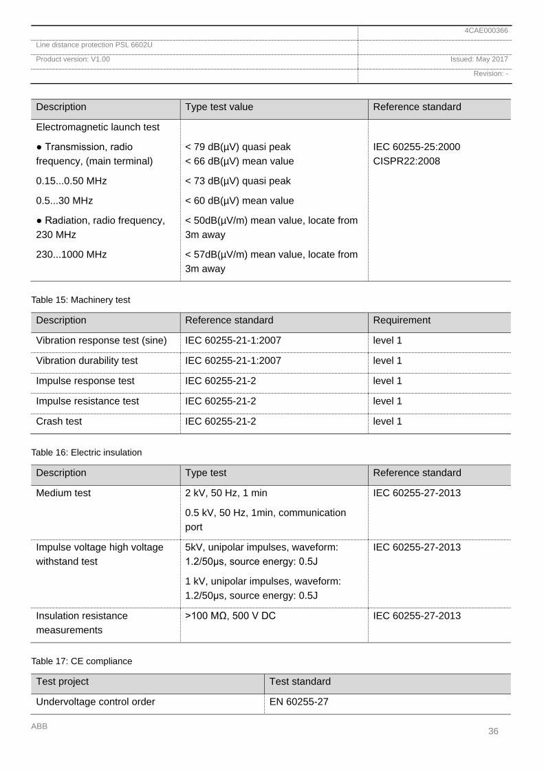
Description Type test value Reference standard
Electromagnetic launch test
Transmission, radio frequency, (main terminal)
0.15...0.50 MHz
0.5...30 MHz
Radiation, radio frequency, 230 MHz
230...1000 MHz
< 79 dB(µV) quasi peak < 66 dB(µV) mean value
< 73 dB(µV) quasi peak
< 60 dB(µV) mean value
< 50dB(µV/m) mean value, locate from 3m away
< 57dB(µV/m) mean value, locate from 3m away
IEC 60255-25:2000 CISPR22:2008
Table 15: Machinery test
Description Reference standard Requirement
Vibration response test (sine) IEC 60255-21-1:2007 level 1
Vibration durability test IEC 60255-21-1:2007 level 1
Impulse response test IEC 60255-21-2 level 1
Impulse resistance test IEC 60255-21-2 level 1
Crash test IEC 60255-21-2 level 1
Table 16: Electric insulation
Description Type test Reference standard
Medium test 2 kV, 50 Hz, 1 min
0.5 kV, 50 Hz, 1min, communication port
IEC 60255-27-2013
Impulse voltage high voltage withstand test
5kV, unipolar impulses, waveform: 1.2/50μs, source energy: 0.5J
1 kV, unipolar impulses, waveform: 1.2/50μs, source energy: 0.5J
IEC 60255-27-2013
Insulation resistance measurements
>100 MΩ, 500 V DC IEC 60255-27-2013
Table 17: CE compliance
Test project Test standard
Undervoltage control order EN 60255-27

4CAE000366
Line distance protection PSL 6602U
Product version: V1.00 Issued: May 2017
Revision: -
ABB 37
Test project Test standard
Electro-magnetic compatibility EN 61000-6-2:2005
EN 61000-6-4:2007+A1
EN 60255-26:2013
Table 18: Dimensions and weight
Project Value
Width 451.6 mm
Height 177 mm (4U)
Depth 291.0 mm
Weight <10 kg (4U)
Table 19: Communication protocol
Function Value
Protocol
Communication speed rate
IEC 61850-8-1
100BASE-FX
Protocol
Communication speed rate
IEC 60870-5-103
4800 - 38400 Bauds for RS 485
100BASE-FX for Ethernet RJ45
4CAE000366
Line distance protection PSL 6602U
Product version: V1.00 Issued: May 2017
Revision: -
ABB 38
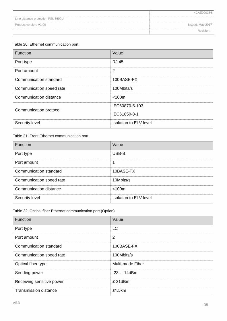
Table 20: Ethernet communication port
Function Value
Port type RJ 45
Port amount 2
Communication standard 100BASE-FX
Communication speed rate 100Mbits/s
Communication distance <100m
Communication protocol IEC60870-5-103
IEC61850-8-1
Security level Isolation to ELV level
Table 21: Front Ethernet communication port
Function Value
Port type USB-B
Port amount 1
Communication standard 10BASE-TX
Communication speed rate 10Mbits/s
Communication distance <100m
Security level Isolation to ELV level
Table 22: Optical fiber Ethernet communication port (Option)
Function Value
Port type LC
Port amount 2
Communication standard 100BASE-FX
Communication speed rate 100Mbits/s
Optical fiber type Multi-mode Fiber
Sending power -23…-14dBm
Receiving sensitive power ≤-31dBm
Transmission distance ≤1.5km
4CAE000366
Line distance protection PSL 6602U
Product version: V1.00 Issued: May 2017
Revision: -
ABB 39
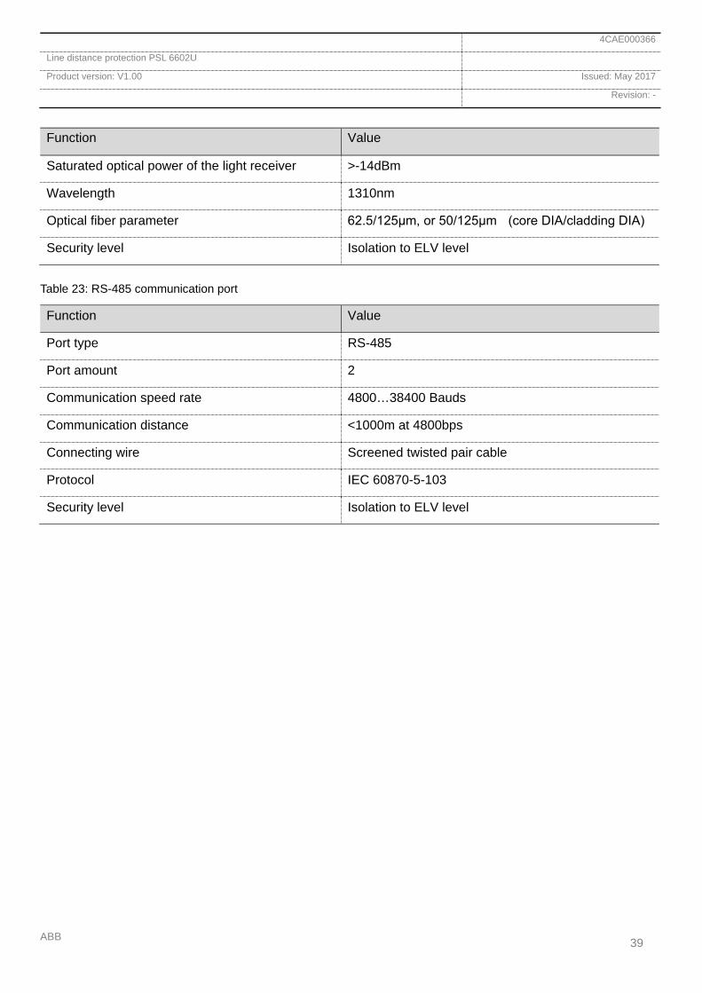
Function Value
Saturated optical power of the light receiver >-14dBm
Wavelength 1310nm
Optical fiber parameter 62.5/125μm, or 50/125μm (core DIA/cladding DIA)
Security level Isolation to ELV level
Table 23: RS-485 communication port
Function Value
Port type RS-485
Port amount 2
Communication speed rate 4800…38400 Bauds
Communication distance <1000m at 4800bps
Connecting wire Screened twisted pair cable
Protocol IEC 60870-5-103
Security level Isolation to ELV level

4CAE000366
Line distance protection PSL 6602U
Product version: V1.00 Issued: May 2017
Revision: -
ABB 40
Table 24: Printer communication port
Function Value
Port type RS-232
Port amount 1
Printing rate of speed 4800…38400bps
Security level Isolation to ELV level
Table 25: Clock synchronization communication port
Function Value
Port type RS-485
Port amount 1
Communication distance <500m
Synchronizing standard PPS, PPM, IRIG-B
Security level Isolation to ELV level
Table 26: Longitudinal communication
Function Value
Optical fiber type Single mode
Light emitting diode Laser diode (LD)
Light receiver Pin Diode
Port amount 2
Port type FC-PC
Central wavelength <60km wavelength: 1310nm
<100km wavelength: 1550nm
Sending power <60km -9…-13dBm
<100km ≥-1dBm
Receive sensitive power ≤-36dBm
Saturated optical power of the light receiver >-3dBm
Communication distance <60km
<100km
4CAE000366
Line distance protection PSL 6602U
Product version: V1.00 Issued: May 2017
Revision: -
ABB 41
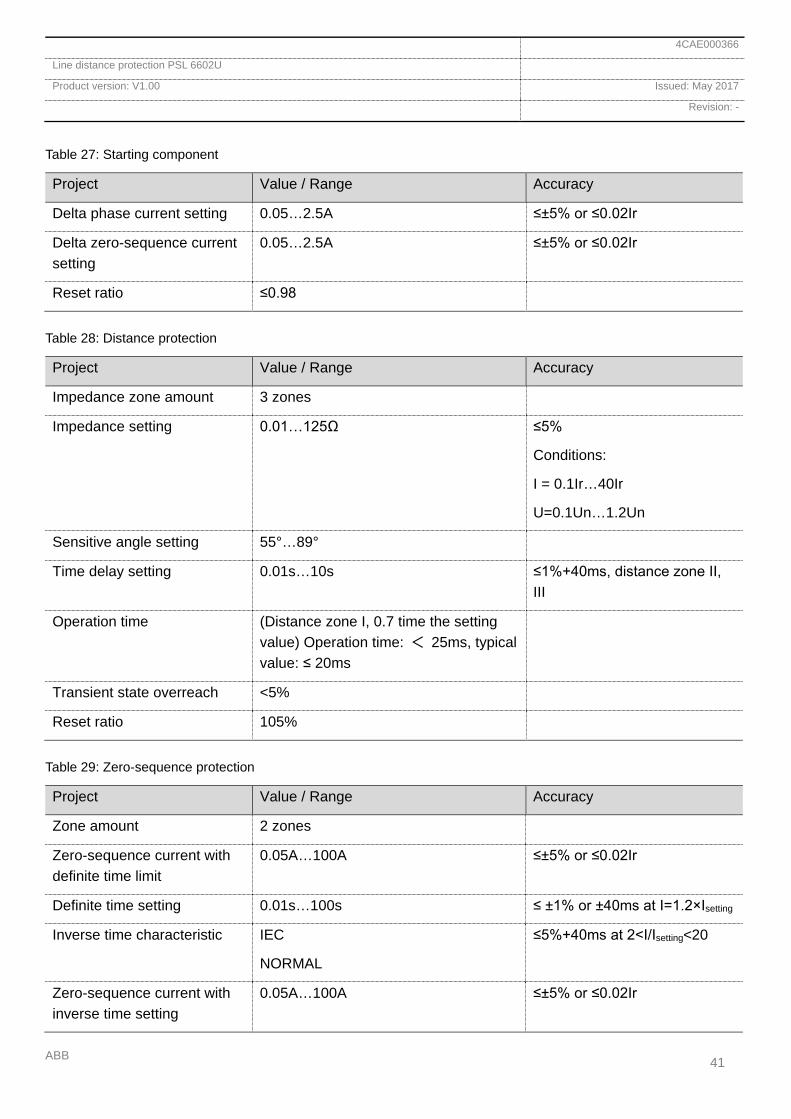
Table 27: Starting component
Project Value / Range Accuracy
Delta phase current setting 0.05…2.5A ≤±5% or ≤0.02Ir
Delta zero-sequence current setting
0.05…2.5A ≤±5% or ≤0.02Ir
Reset ratio ≤0.98
Table 28: Distance protection
Project Value / Range Accuracy
Impedance zone amount 3 zones
Impedance setting 0.01…125Ω ≤5%
Conditions:
I = 0.1Ir…40Ir
U=0.1Un…1.2Un
Sensitive angle setting 55°…89°
Time delay setting 0.01s…10s ≤1%+40ms, distance zone II, III
Operation time (Distance zone I, 0.7 time the setting value) Operation time: < 25ms, typical value: ≤ 20ms
Transient state overreach <5%
Reset ratio 105%
Table 29: Zero-sequence protection
Project Value / Range Accuracy
Zone amount 2 zones
Zero-sequence current with definite time limit
0.05A…100A ≤±5% or ≤0.02Ir
Definite time setting 0.01s…100s ≤ ±1% or ±40ms at I=1.2×Isetting
Inverse time characteristic IEC
NORMAL
≤5%+40ms at 2<I/Isetting<20
Zero-sequence current with inverse time setting
0.05A…100A ≤±5% or ≤0.02Ir

4CAE000366
Line distance protection PSL 6602U
Product version: V1.00 Issued: May 2017
Revision: -
ABB 42
Project Value / Range Accuracy
Inverse time setting 0.1s…10s ≤5% or +40ms
Table 30: Fuse failure overcurrent protection
Project Value / Range Accuracy
Current setting 0.05A…100A ≤±5% or ≤0.02Ir
Zero-sequence current setting
0.05A…100A ≤±5% or ≤0.02Ir
Definite time setting 0.01s…100s ≤ ±1% or ±40ms at I=1.2×Isetting
Reset ratio 98%
Table 31: Pole discordance protection
Project Value / Range Accuracy
Current setting 0.05A…2.5A ≤2.5%
Definite time setting 0.01s…100s ≤ ±1% or ±40ms at I=1.2×Isetting
Reset ratio 98%
Table 32: Reclosing
Project Value / Range Accuracy
Time setting 0.01s…10s ≤ ±1% or ±40ms
Synchronizing angle setting 0°…90°
4CAE000366
Line distance protection PSL 6602U
Product version: V1.00 Issued: May 2017
Revision: -
ABB 43
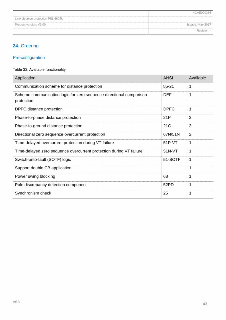
24. Ordering
Pre-configuration
Table 33: Available functionality
Application ANSI Available
Communication scheme for distance protection 85-21 1
Scheme communication logic for zero sequence directional comparison protection
DEF 1
DPFC distance protection DPFC 1
Phase-to-phase distance protection 21P 3
Phase-to-ground distance protection 21G 3
Directional zero sequence overcurrent protection 67N/51N 2
Time-delayed overcurrent protection during VT failure 51P-VT 1
Time-delayed zero sequence overcurrent protection during VT failure 51N-VT 1
Switch-onto-fault (SOTF) logic 51-SOTF 1
Support double CB application 1
Power swing blocking 68 1
Pole discrepancy detection component 52PD 1
Synchronism check 25 1
4CAE000366
Line distance protection PSL 6602U
Product version: V1.00 Issued: May 2017
Revision: -
ABB 44
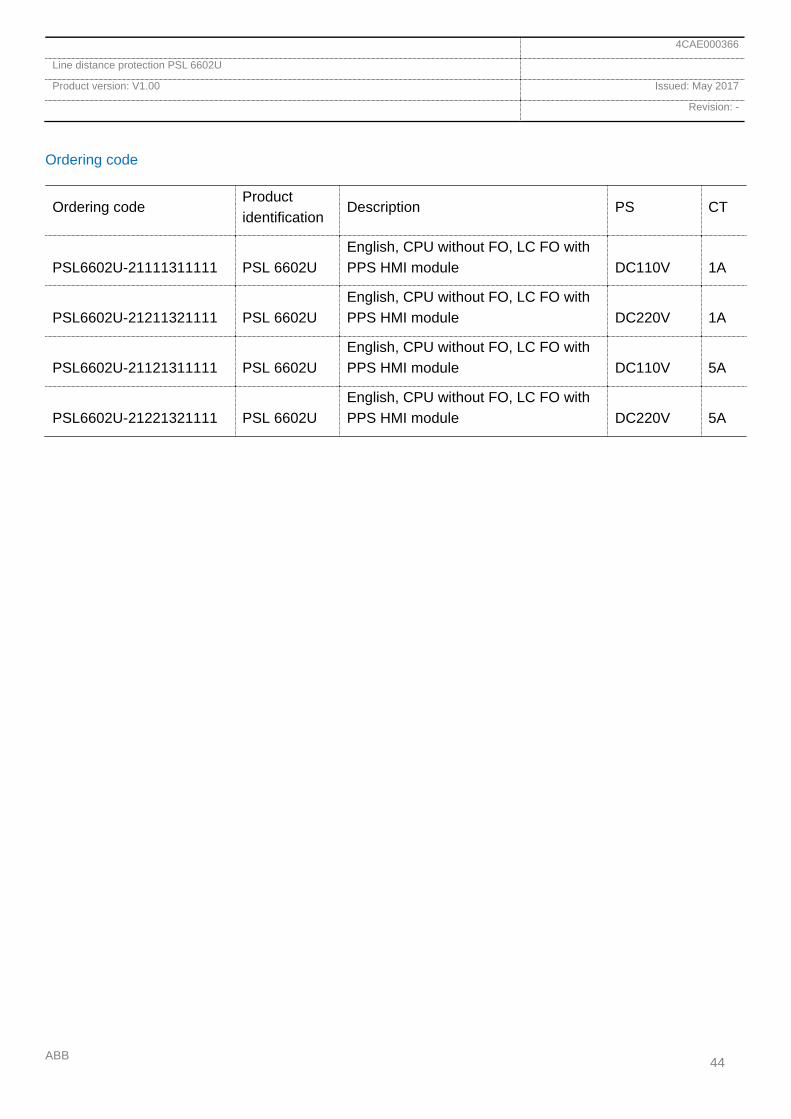
Ordering code
Ordering code Product identification
Description PS CT
PSL6602U-21111311111 PSL 6602U English, CPU without FO, LC FO with PPS HMI module DC110V 1A
PSL6602U-21211321111 PSL 6602U English, CPU without FO, LC FO with PPS HMI module DC220V 1A
PSL6602U-21121311111 PSL 6602U English, CPU without FO, LC FO with PPS HMI module DC110V 5A
PSL6602U-21221321111 PSL 6602U English, CPU without FO, LC FO with PPS HMI module DC220V 5A
—ABB AB Grid Automation Products721 59 Västerås, SwedenPhone: +46 (0) 21 32 50 00
abb.com/protection-control
4C
AE
00
036
6 R
ev-
© Copyright 2017 ABB. All rights reserved. Specifications subject to change without notice.