line coding - sonoma state university · in analog and digital communications, ... line coding is...
TRANSCRIPT
Line Coding EE 442 – Spring 2017
Lecture 11
1
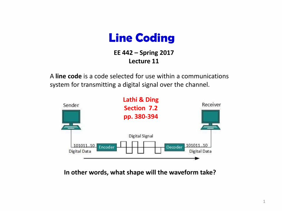
A line code is a code selected for use within a communications system for transmitting a digital signal over the channel.
Lathi & Ding Section 7.2 pp. 380-394
In other words, what shape will the waveform take?

2
Preliminary: Bit Rate vs. Symbol Rate (Baud Rate)
The speed of data is commonly expressed in bits/second or bytes/second. The data rate Rb is related to the bit period Tb (duration of a bit).
Rb = 1/Tb
The bit rate is commonly referred to as the channel capacity.
Communication systems use symbols to convey information. A symbol may be one bit per symbol (called binary), or a group of bits, or a collection of defined voltage levels (multiple level symbols), etc.
The symbol rate RS is related to the symbol’s period (or duration) TS by
RS = 1/TS
The symbol rate is also called Baud rate. Bit rate Rb can be written as
Rb = RSlog2( ) = RSn
where = 2n = number of levels (for n bits per symbol).
3
Signal-to-Noise Ratio vs. Energy/Bit-to-Noise Ratio
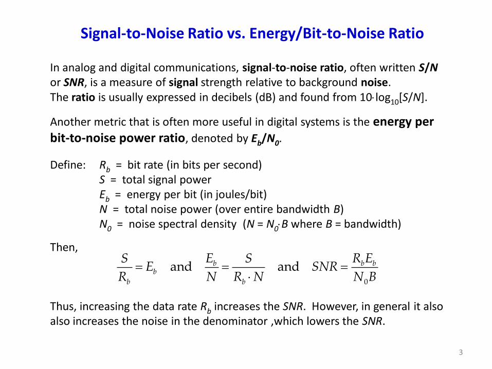
In analog and digital communications, signal-to-noise ratio, often written S/N or SNR, is a measure of signal strength relative to background noise. The ratio is usually expressed in decibels (dB) and found from 10log10[S/N].
Another metric that is often more useful in digital systems is the energy per bit-to-noise power ratio, denoted by Eb/N0.
Define: Rb = bit rate (in bits per second) S = total signal power Eb = energy per bit (in joules/bit) N = total noise power (over entire bandwidth B) N0 = noise spectral density (N = N0B where B = bandwidth)
Then, Thus, increasing the data rate Rb increases the SNR. However, in general it also also increases the noise in the denominator ,which lowers the SNR.
0
and andb b bb
b b
E R ES SE SNR
R N R N N B

4
Signal-to-Noise Ratio vs. Energy/Bit-to-Noise Ratio (continued)
In digital communications systems the Eb/N0 ratio can be thought of as a “normalized signal-to-noise ratio. “ We can roughly equate signal power to energy per bit by Eb = PsignalTS , where TS is the symbol period, and the noise power per hertz, denoted by N0 , is the total noise power N divided by bandwidth B. Eb/N0 is commonly used to as the primary variable in establishing the bit error rate for all modulation schemes.

5
Categories of Line Coding – Overview
Uni-Polar Polar Bipolar Multi-level Multi-
transition
Line Coding
A line code is a specific code (with precisely defined parameters) used for transmitting a digital signal over a channel. Line coding is used in digital data transport – the pattern of voltage, current or photons used to represent digital data on a transmission link is called line encoding.
We primarioy focus upon these in EE442
6
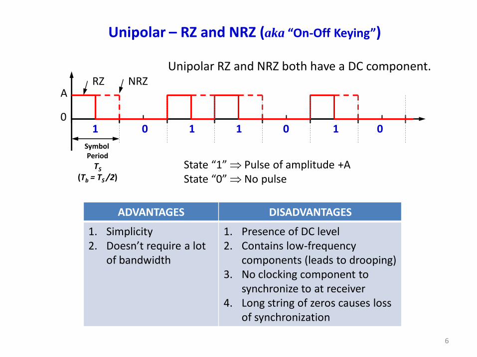
Unipolar – RZ and NRZ (aka “On-Off Keying”)
RZ NRZ
State “1” Pulse of amplitude +A State “0” No pulse
Unipolar RZ and NRZ both have a DC component.
1 0 1 1 0 1 0
A
Symbol Period
TS
(Tb = TS /2)
0
ADVANTAGES DISADVANTAGES
1. Simplicity 2. Doesn’t require a lot
of bandwidth
1. Presence of DC level 2. Contains low-frequency
components (leads to drooping) 3. No clocking component to
synchronize to at receiver 4. Long string of zeros causes loss
of synchronization
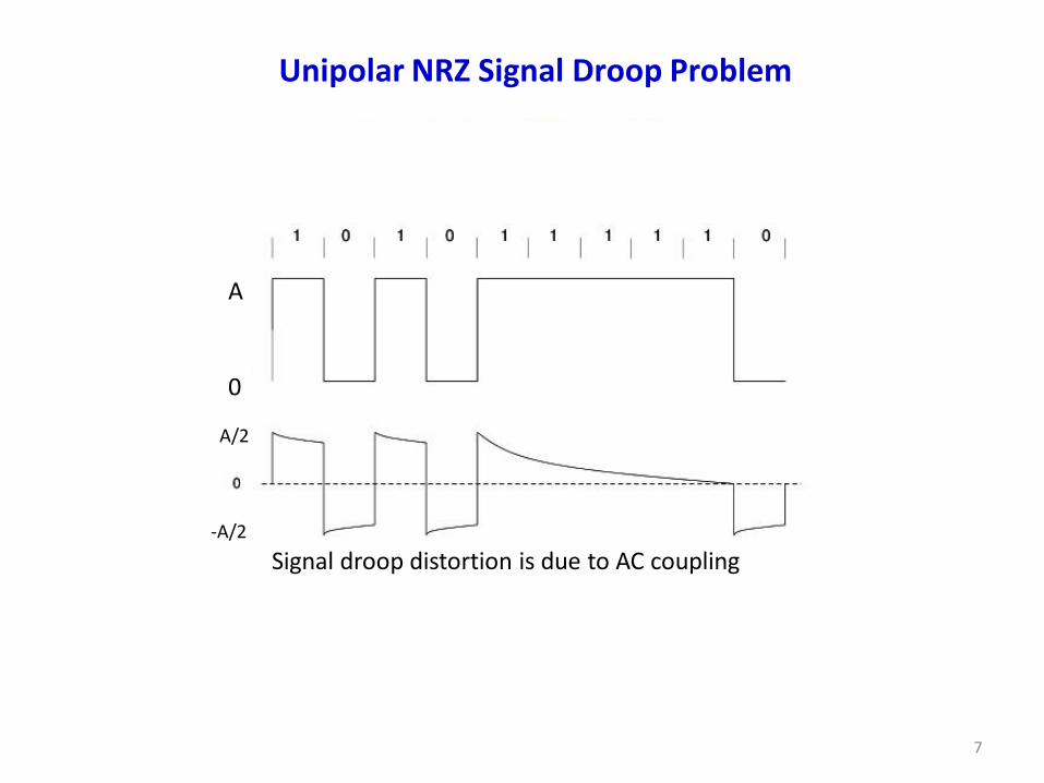
Signal droop distortion is due to AC coupling
A/2
-A/2
7
Unipolar NRZ Signal Droop Problem
A
0
8
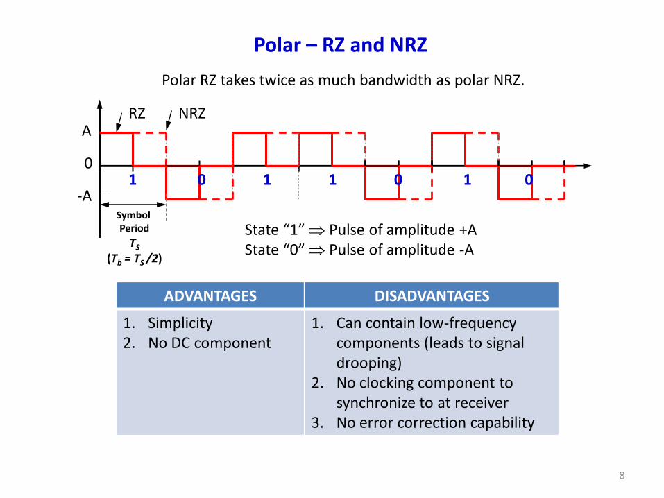
Polar – RZ and NRZ
Polar RZ takes twice as much bandwidth as polar NRZ.
ADVANTAGES DISADVANTAGES
1. Simplicity 2. No DC component
1. Can contain low-frequency components (leads to signal drooping)
2. No clocking component to synchronize to at receiver
3. No error correction capability
RZ NRZ
State “1” Pulse of amplitude +A State “0” Pulse of amplitude -A
A
0 1 0 1 1 0 1 0
-A Symbol Period
TS
(Tb = TS /2)

9
Power Spectral Density Example: Polar NRZ Signal
http://www.ni.com/white-paper/14766/en/
Tb
Polar NRZ
t
Sinc squared function
There is no DC component.
Lathi & Ding Figure 7.6 Page 387
Rb = 1/Tb

10
Bipolar NRZ
ADVANTAGES DISADVANTAGES
1. No DC component 2. Less bandwidth than
for unipolar & polar NRZ
3. No signal droop problem
1. No clocking component to synchronize to at receiver
2. Limited error correction capability
Uses three levels of signal level (+A, 0, -A) Has “Alternate Mark Inversion” – AMI
State “1” Alternating levels of +A and -A State “0” No pulse
A
0 1 0 1 1 0 1 0
-A Symbol Period
TS
NRZ
11
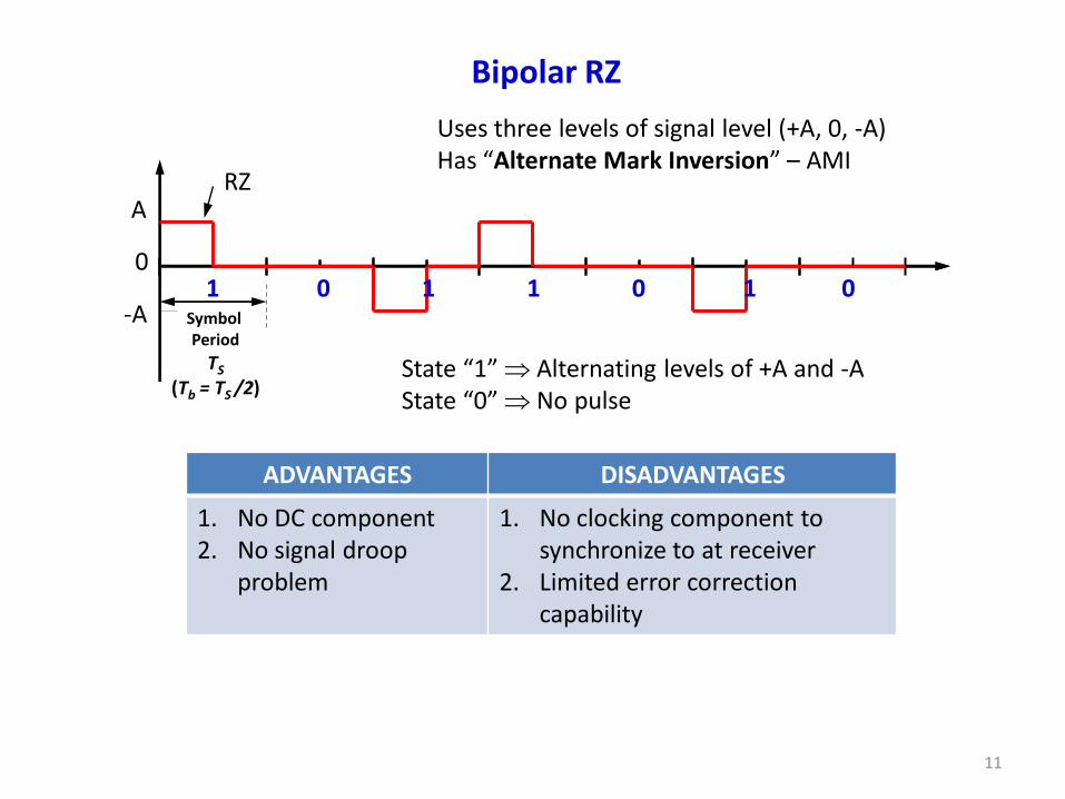
Bipolar RZ
ADVANTAGES DISADVANTAGES
1. No DC component 2. No signal droop
problem
1. No clocking component to synchronize to at receiver
2. Limited error correction capability
Uses three levels of signal level (+A, 0, -A) Has “Alternate Mark Inversion” – AMI
State “1” Alternating levels of +A and -A State “0” No pulse
A
0
-A
RZ
1 0 1 1 0 1 0 Symbol Period
TS
(Tb = TS /2)

12
Manchester (Bi-Phase or Split-Phase) Encoding
ADVANTAGES DISADVANTAGES
1. No DC component 2. No signal droop
problem 3. Easy to synchronize to
the waveform
1. Greater bandwidth required for this waveform
2. No error correction capability
State “1” +A in 1st half of TS and –A in 2nd half State “0” -A in 1st half of TS and +A in 2nd half
A
0
-A
RZ
TS
There is a transition at the center of every symbol period.
1 0 1 1 0 1 0
The duration of a symbol is divided into two halves.

13
Manchester (Bi-Phase or Split-Phase) Encoding
• Manchester encoding is a form of binary phase-shift keying (BPSK). • It is designed to encode both the clock and the data in a bit stream. • This is also referred to “self-synchronizing data steam.” • Manchester encoding has the disadvantage of requiring higher frequencies. • It is used in Ethernet (IEEE 802.3 standard) with lower data rates. • Also used for consumer IR protocols and in some RFID systems.

14
Differential Manchester (Bi-Phase) Encoding
0 1 0 0 1 1
0 1 0 0 1 1
0 is
1 is t
t
Manchester (or Bi-Phase)
Differential Manchester
Transition always is in middle of period of
symbol period
1 → Forces transition at beginning 0 → Do nothing
15
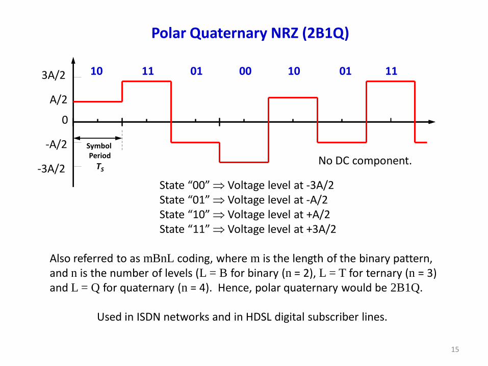
Polar Quaternary NRZ (2B1Q)
State “00” Voltage level at -3A/2 State “01” Voltage level at -A/2 State “10” Voltage level at +A/2 State “11” Voltage level at +3A/2
A/2
0
-A/2 Symbol Period
TS
3A/2 10 11 01 00 10 01 11
-3A/2
Also referred to as mBnL coding, where m is the length of the binary pattern, and n is the number of levels (L = B for binary (n = 2), L = T for ternary (n = 3) and L = Q for quaternary (n = 4). Hence, polar quaternary would be 2B1Q.
Used in ISDN networks and in HDSL digital subscriber lines.
No DC component.

16
Bandwidth Efficiency

17
What Are the Primary Considerations When Comparing Line Codes?
1. We want the transmission bandwidths to be as small as possible. 1. Power efficiency – Keep power as low as possible.
2. Error detection and correction capability – error correcting codes are a special topic 4. Favorable Power Spectral Density – We want zero power at DC ( f = 0 ) to avoid baseline drift.
5. Adequate timing content – Often we must extract the timing or clock information from the signal. 6. Transparency – This means for every possible sequence of data the coded signal is received faithfully. 7. Signal is easily regenerated by repeaters.
18
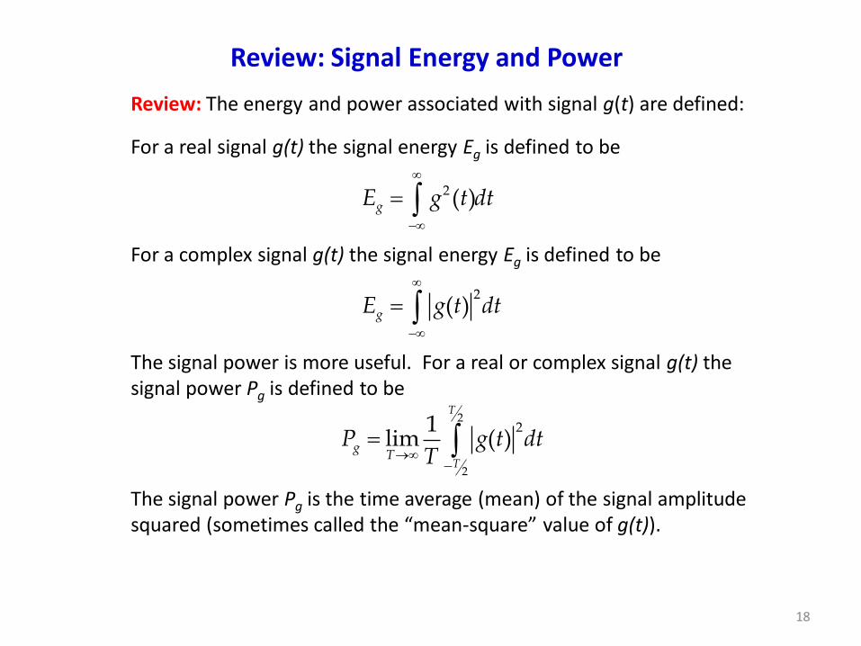
Review: Signal Energy and Power
For a real signal g(t) the signal energy Eg is defined to be
2( )gE g t dt
For a complex signal g(t) the signal energy Eg is defined to be
2( )gE g t dt
The signal power is more useful. For a real or complex signal g(t) the signal power Pg is defined to be
2
2
21lim ( )
T
T
gT
P g t dtT
The signal power Pg is the time average (mean) of the signal amplitude squared (sometimes called the “mean-square” value of g(t)).
Review: The energy and power associated with signal g(t) are defined:

19
Concept of Power Spectral Density
Suppose we have signal gT(t) with Fourier transform GT(f). The subscript T indicates a signal of finite duration.
Then the power spectral density (PSD) is defined as The power is the area under a PSD. PSD is a positive, real and even function of frequency f. Example: If g(t) is a voltage signal, then the units of the PSD are volts-squared per hertz (V2/Hz).
21Power of ( ) = lim ( )g T
Tg t P G f df
T
2( )
( ) lim T
gT
G fS f
T
The power spectral density function (PSD) gives the strength of the variations (energy) of gT(t) as a function of frequency f.

20
Example: Power Spectral Density of Human Speech
PSD
Voltage: waveform of speech
Frequency from 0 Hz to 4,000 Hz
Spectrum of a voice signal over a 15 second duration:
Time Domain Frequency Domain

21
Power Spectral Density of NRZ and Polar NRZ Waveforms
Binary data
Binary data
NRZ
Polar NRZ
BTb
PSD
(W/H
z)
DC term
PSD
(W
/Hz)
After L. W. Couch, 8th ed., Digital and Analog Communication Systems; p.170.
22
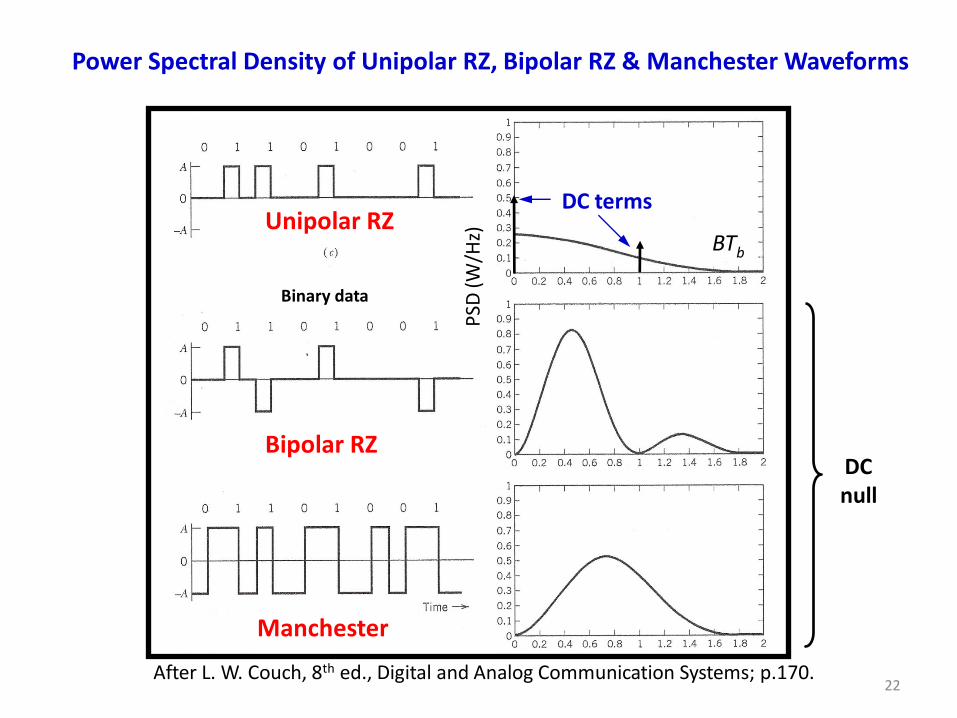
Power Spectral Density of Unipolar RZ, Bipolar RZ & Manchester Waveforms
Binary data
Unipolar RZ
Bipolar RZ
Manchester
DC null
BTb
PSD
(W/H
z)
DC terms
After L. W. Couch, 8th ed., Digital and Analog Communication Systems; p.170.

23
Comparing Power Spectral Densities for Polar, Bipolar and Manchester
1b
b
RT
(also known as Manchester)
Lathi & Ding Figure 7.9 Page 392
24
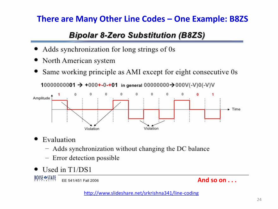
There are Many Other Line Codes – One Example: B8ZS
http://www.slideshare.net/srkrishna341/line-coding
And so on . . .
25
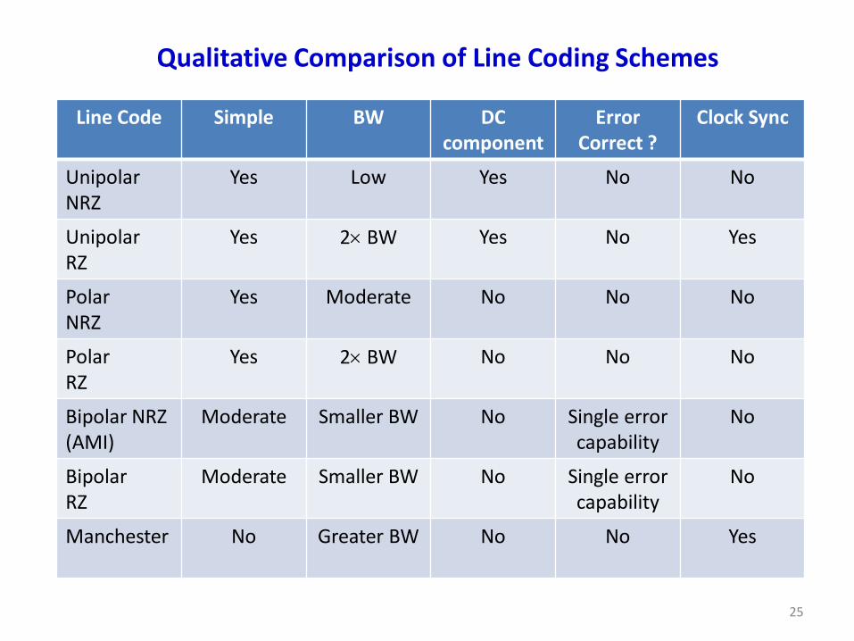
Qualitative Comparison of Line Coding Schemes
Line Code Simple BW DC component
Error Correct ?
Clock Sync
Unipolar NRZ
Yes Low Yes No No
Unipolar RZ
Yes 2 BW Yes No Yes
Polar NRZ
Yes Moderate No No No
Polar RZ
Yes 2 BW No No No
Bipolar NRZ (AMI)
Moderate Smaller BW No Single error capability
No
Bipolar RZ
Moderate Smaller BW No Single error capability
No
Manchester
No Greater BW No No Yes
26
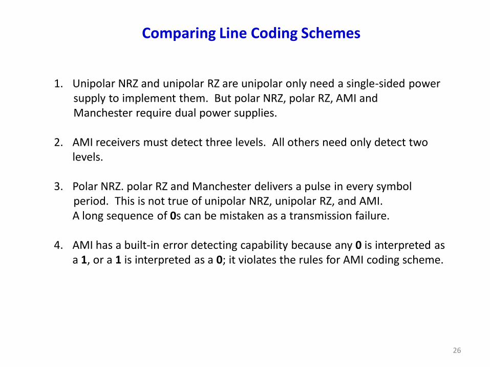
Comparing Line Coding Schemes
1. Unipolar NRZ and unipolar RZ are unipolar only need a single-sided power supply to implement them. But polar NRZ, polar RZ, AMI and Manchester require dual power supplies. 2. AMI receivers must detect three levels. All others need only detect two levels. 3. Polar NRZ. polar RZ and Manchester delivers a pulse in every symbol period. This is not true of unipolar NRZ, unipolar RZ, and AMI.
A long sequence of 0s can be mistaken as a transmission failure. 4. AMI has a built-in error detecting capability because any 0 is interpreted as a 1, or a 1 is interpreted as a 0; it violates the rules for AMI coding scheme.
27
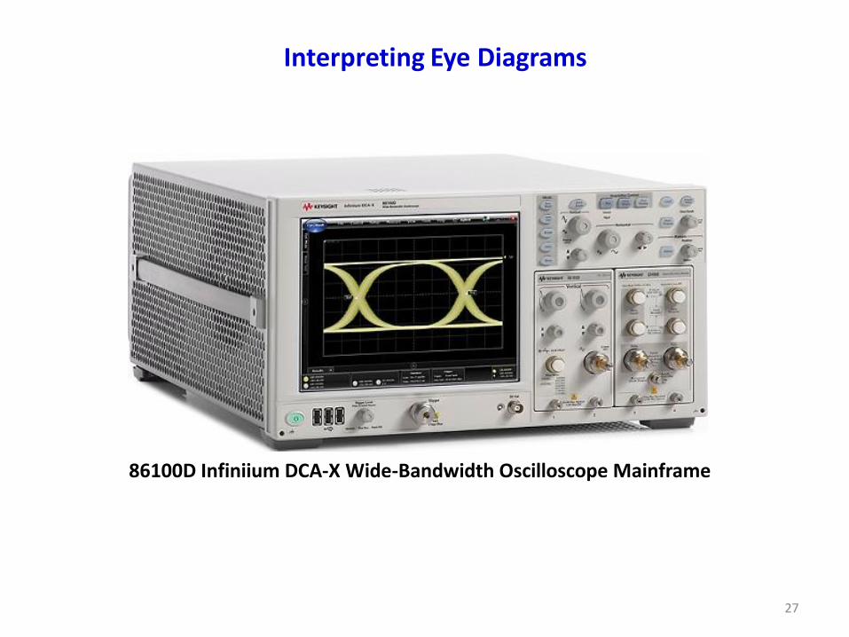
Interpreting Eye Diagrams
86100D Infiniium DCA-X Wide-Bandwidth Oscilloscope Mainframe

28
Oscilloscope with Memory for Displaying Multiple Traces
Data stream of pulses
(a)
Display window of oscilloscope – trigger sets the beginning of each trace or window

29
spec spec
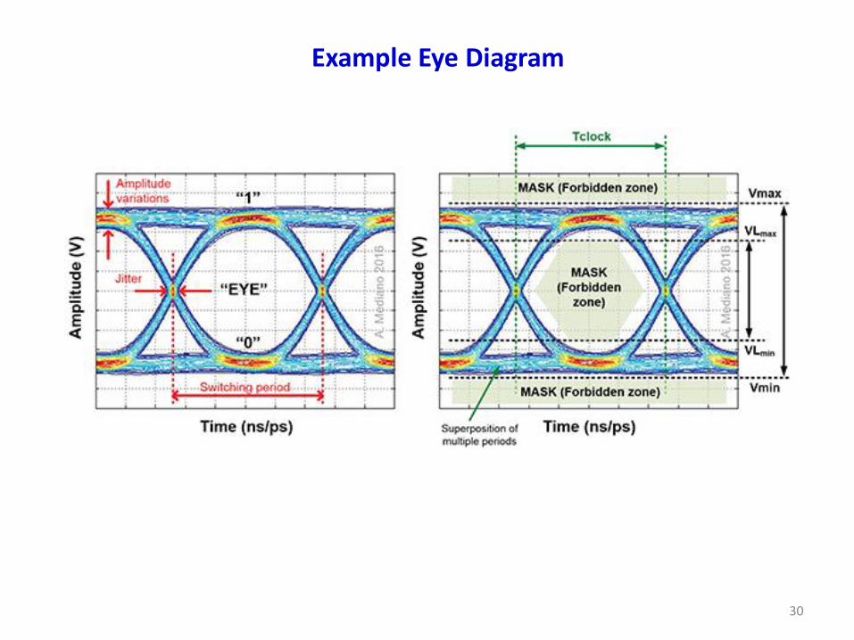
Eye Diagrams for Digital Signals
In telecommunication, an eye pattern, also known as an eye diagram, is an oscilloscope display in which a digital signal from a receiver is repetitively sampled and applied to the vertical input, while the data rate is used to trigger the horizontal sweep.
30
Example Eye Diagram

31
Waveform 2
What is this Eye Diagram telling us?
32
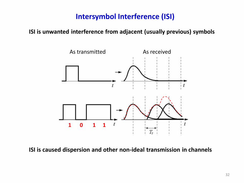
ISI is unwanted interference from adjacent (usually previous) symbols
Intersymbol Interference (ISI)
ISI is caused dispersion and other non-ideal transmission in channels
1 0 1 1
As transmitted As received
33
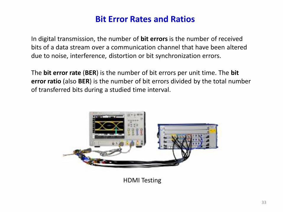
In digital transmission, the number of bit errors is the number of received bits of a data stream over a communication channel that have been altered due to noise, interference, distortion or bit synchronization errors. The bit error rate (BER) is the number of bit errors per unit time. The bit error ratio (also BER) is the number of bit errors divided by the total number of transferred bits during a studied time interval.
Bit Error Rates and Ratios
HDMI Testing
34
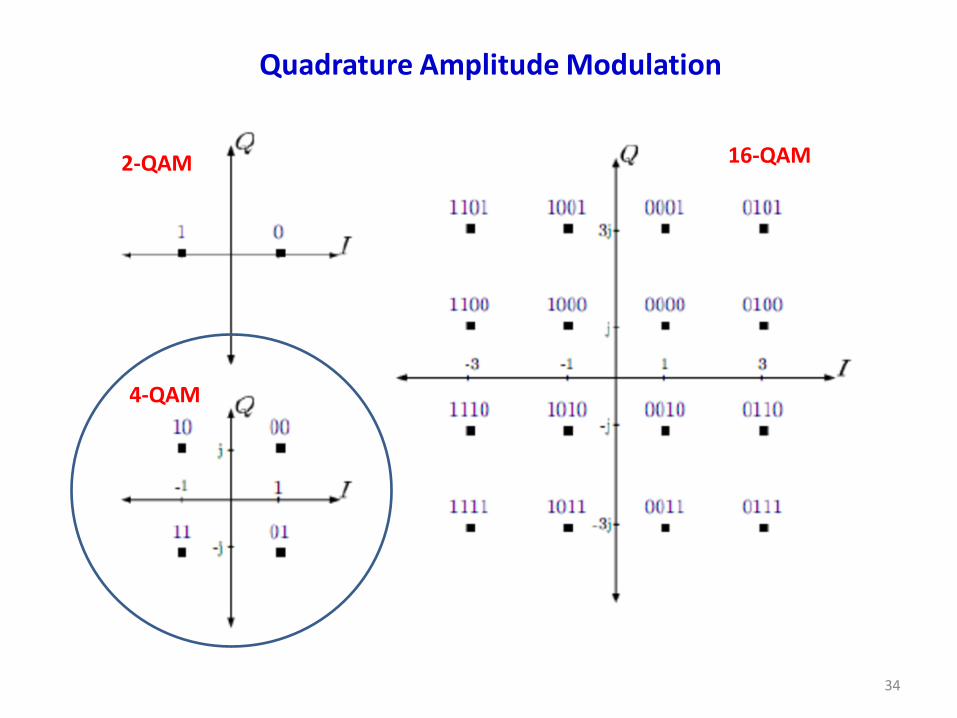
Quadrature Amplitude Modulation
2-QAM
4-QAM
16-QAM

35
Bit Error Rate (BER) Measurement
Number of bit errors
Total number of bits transmittedBER
How many bits in the PRBS bit pattern stream? The lowest BERmin to be measured should have a PRBS length equals 3 (1/BERmin). Example: For BERmin = 10-9, then length > 3 109 bits.
PRBS Bit Stream
PRBS = pseudo-random bit sequence
4-QAM
36
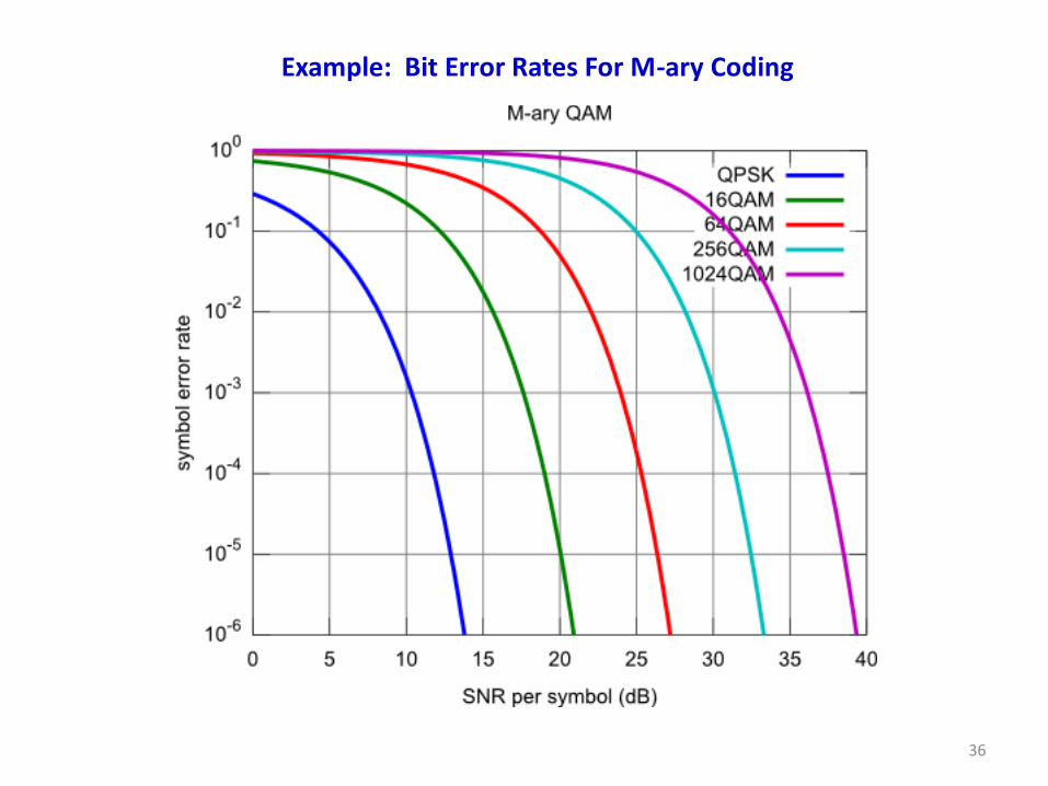
Example: Bit Error Rates For M-ary Coding
37
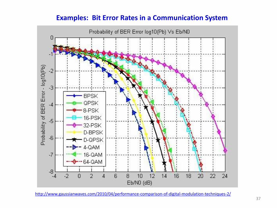
Examples: Bit Error Rates in a Communication System
http://www.gaussianwaves.com/2010/04/performance-comparison-of-digital-modulation-techniques-2/

38
1. Digital is more robust than analog to noise and interference†
2. Digital is more viable to using regenerative repeaters
3. Digital hardware more flexible by using microprocessors and VLSI
4. Can be coded to yield extremely low error rates with error correction
5. Easier to multiplex several digital signals than analog signals
6. Digital is more efficient in trading off SNR for bandwidth
7. Digital signals are easily encrypted for security purposes
8. Digital signal storage is easier, cheaper and more efficient
9. Reproduction of digital data is more reliable without deterioration
10. Cost is coming down in digital systems faster than in analog systems and DSP algorithms are growing in power and flexibility
Reference: Lathi & Ding; Section 6.2.1 on pages 321 and 322.
† Analog signals vary continuously and their value is affected by all levels of noise.
Advantages of Digital Over Analog For Communications