limitation changes - dtic.mil filelimitation changes to: approved for public release, distribution...
TRANSCRIPT

UNCLASSIFIED
AD NUMBERAD011171
CLASSIFICATION CHANGES
TO: unclassified
FROM: restricted
LIMITATION CHANGES
TO:Approved for public release, distributionunlimited
FROM:
Distribution authorized to U.S. Gov't.agencies and their contractors;Administrative/Operational Use; JUN 1953.Other requests shall be referred toNational Aeronautics and SpaceAdministration, Washington, DC.
AUTHORITY11 Dec 1953 per NACA Reclass notice no. 56dtd 13 Jan 1954; NASA Technical ReportsServer website
THIS PAGE IS UNCLASSIFIED

Reproduced by
Armed Services Technical Information AgencDOCUMENT SERVICE CENTER
KNOTT BUILDING, DAYTON, 2, OHIO
RESTRICTED'

SECURITY INFORMATION
RESTRICTED RM L53D09
C.J5
1V0
RESEARCH MEMORANDUM
LOW-SPEED, LARGE-SCALE INVESTIGATION OF AERODYNAMIC
CHARACTERISTICS OF A SEMISPAN 490 SWEPTBACK WING
WITH A FOWLER FLAP IN COMBINATION WITH
A PLAIN FLAP, SLATS, AND FENCES
By Edward F. Whittle, Jr., and Stanley Lipson
Langley Aeronautical LaboratoryLangley Field, Va.
CLASSIFIED DOCUMENT
This material contains information affecting the National Defense of the United States within the meaningof the espionage laws, Title 18, U.S.C., Sacs. 793 and 794, the transmission or revelation of which in anymanner to an unauthorized person is prohibited by law,
NATIONAL ADVISORY COMMITTEEFOR AERONAUTICS
WASHI NGTONJune 5, 1953
RESTRICTED

NACA RM L53D09 RESTRICTED
NATIONAL ADVISORY COMMITTEE FOR AERONAUTICS
RESEARCH MEMORANDUM
LOW-SPEED, LARGE-SCALE INVESTIGATION OF AERODYNAMIC
CHARACTERISTICS OF A SEMISPAN 490 SWEPTBACK WING
WITH A FOWLER FLAP IN COMBINATION WITH
A PLAIN FLAP, SLATS, AND FENCES
By Edward F. Whittle, Jr., and Stanley Lipson
SUMMARY
An investigation has been conducted in the Langley full-scaletunnel to determine the effects of a Fowler type slotted flap on theaerodynamic characteristics of a semispan 49.10 sweptback wing havingNACA 65A006 airfoil sections streamwise, an aspect ratio of 5.78, anda taper ratio of 0.59. Various slat and fence arrangements were testedin combination with the Fowler flap. The effect of longitudinal andvertical location of the Fowler flap was investigated over a limitedrange of positions.
In addition, tests were made of a configuration having the Fowlerflap located near the trailing edge of a plain flap. When the flapswere deflected, this arrangement tended to produce a double-camberedsurface at the rear portion of the wing.
The tests were conducted at Reynolds numbers of 6.1 x 10⁶ and4.4 x 106 with corresponding Mach numbers of 0.10 and 0.07, respectively.
INTRODUCTION
As part of a general investigation, at l-rge scale, of means ofimproving the low-speed static longitudinal aerodynamic characteristicsof high-speed wing plan forms, tests have been conducted in the Langleyfull-scale tunnel on a 49.10 sweptback wing equipped with various high-lift and stall-control devices. The wing had an aspect ratio of 3.78,a taper ratio of 0.59, and NACA 65A006 airfoil sections parallel to theplane of symmetry. References 1 and 2 present the results of pressureand force measurements made with various slat, plain trailing-edge flap,and fence arrangements.
RESTRICTED

2 RESTRICTED NACA RM L53D09
This paper presents the results of force tests made, with the maineffort directed toward increased lift, on the semispan sweptback wingequipped with a 0.47-semispan Fowler type slotted flap located at severallongitudinal and vertical positions. The effect of various slat andfence arrangements on the characteristics of the flapped wing was alsoinvestigated. In addition, tests were made of a configuration havingthe Fowler flap located near the trailing edge of a deflected plainflap.
The tests were made at Reynolds numbers of 6.1 X 10⁶ and 4 .4 x 06,
with corresponding Mach numbers of 0.10 and 0.67, respectively.
COEFFICIENTS AND SYMBOLS
The data are referred to the wind axes with the origin at thequarter-chord point of the mean aerodynamic chord. The data have beenreduced to standard NACA nondimensional coefficients which, togetherwith the symbols, are defined as follows:
CL lift coefficient, 2L/qoS
CLa=0O lift coefficient at 00 angle of attack
LcIa=0 value of CLa=o for any configuration minus value of
CL=0 for basic wing
C1Max maximum lift coefficient
60Tmax value of CLmax for any configuration minus value of
CLmax for basic wing
2 X Model dragCD drag coefficient,
qoS
Cm pitching-moment coefficient about quarter-chord point of2 x Model pitching momentmean aerodynamic chord,
qoSF
b twice model span, ft
c local wing chord measured parallel to plane of symmetry, ft
RESTRICTED

NACA RM L53D09 RESTRICTED 3
!c local wing chord measured perpendicular to center line ofa corresponding unswept wing, ft
c f local trailing-edge-flap chord measured perpendicular to0.50c' line, ft
c 8 local slat chord measured perpendicular to 0.50c' line, ft
- 2 b/2c mean aerodynamic chord, 2 b0 c2 dy, ft
h distance from wing leading edge to hinge line of Fowler
flap, measured perpendicular to 0.50c' line, ft
L model lift, lb
M bending moment at wing root, ft-lb
v perpendicular distance from plain-flap chord plane tohinge line of Fowler flap, ft
qo free-stream dynamic pressure, -- , lb/sq ft
R Reynolds number, pVF/4
S twice model wing area, sq ft
V free-stream velocity, ft/sec
y spanwise coordinate perpendicular to plane of symmetry, ft
(c.p.)y spanwise location of wing center of pressure, M/L
angle of attack, deg
bpf plain-flap deflection measured relative to wing chord linein a plane perpendicular to 0.50c' line, deg
8ff Fowler flap deflection measured relative to chord line ofplain flap in a plane perpendicular to 0.50c' line, deg
6ff' Fowler flap deflection measured relative to wing chord linein a plane perpendicular to 0.50c' line, 5ff + 5pf, deg
RESTRICTED

4 RESTRICTED NACA RM L55D09
p mass density of air, slugs/cu ft
coefficient of viscosity, slugs/ft-sec
MODEL
The geometric characteristics and principal dimensions of the semi-span wing are given in figure 1. Details of the high-lift and stall-control devices (plain flap, Fowler flap, slat, and fences) togetherwith section views of the various combinations tested are shown in fig-ure 2. The semispan wing is shown mounted on a reflection plane in theLangley full-scale tunnel in figure 5. A description of the reflectionplane is presented in reference 5. The wing has 49.10 of sweepback atthe leading edge, an aspect ratio of 3.78, a taper ratio of 0.59, andno geometric twist or dihedral. The airfoil sections parallel to theplane of symmetry are NACA 65A006 sections. The wing tip is half of abody of revolution based on the same airfoil section ordinates.
The high-lift and stall-control devices used were: a 0.25c' plainflap having a span of 0.469b/2; a 0.20c' Fowler flap having a span of0.469b/2; 0.15c' leading-edge slats of various lengths; and variouscombinations of chordwise fences, having a height of 0.06c, installedat various spanwise stations. (See table I.) The fences were made of1/4-inch plywood and were mounted parallel to the plane of symmetry.For all configurations on which the nose of the fences intersected theslat, and for one case where the spanwise location of a fence practi-cally coincided with the inboard end of the slat, the fences were cutoff at 0.05c (see fig. 2(b)). The nose and upper surface of the slathad the airfoil ordinates of the wing but the slat was not an integralpart of the wing and was mounted directly on the unmodified leadingedge of the basic wing with the slat brackets alined normal to the wingleading edge. The minimum chordwise clearance between the slat andwing and the distance of the slat nose ahead of the wing were selectedfrom the slat-positioning results for two-dimensional flow (ref. 4).Further details of the slat arrangement may be obtained from reference 1.
The Fowler flap was constructed of wood and had a 15-percent-thicksymmetrical airfoil section whose ordinates were such as to permit itsretraction within the plain flp:). The plain flap was made of steelplate and was contoured so as to duplicate the flap employed in thetests of reference 2. Except for one test, whenever the Fowler flapwas deflected the undersurface of the plain flap was removed (seefig. 2(a)) in order to simulate more realistically a productionconfiguration.
RESTRICTED

I
NACA RM L53D09 RESTRICTED 5
The Fowler flap was manually positioned and deflected, and wasrigidly attached to the plain flap by means of steel brackets (fig. 3(b)).The plain flap was automatically deflected through the use of two elec-trically powered actuators installed on the lower surface of the winginside of streamlined fairings (fig. 3(b)). With the Fowler flapinstalled, deflection of the plain flap produced a double-camberedsurface at the rear of the wing (fig. 2(b)).
TESTS AND CORRECTIONS
The model configurations tested are detailed in table I. Forcedata (lift, drag, pitching moment, and bending moment) were obtainedthrough an angle-of-attack range from about -40 to 320 and at Reynolds
numbers of 4.4 X 10⁶ and 6.1 x 10⁶ with corresponding Mach numbers of0.07 and 0.10, respectively. With the fences installed it was necessaryto conduct the tests at a Reynolds number of 4.4 X 10⁶ because thefences tended to vibrate in the high lift-coefficient range at thehigher tunnel speed corresponding to a Reynolds number of 6.1 X 10⁶.
The data have been corrected for airstream misalinement, blockingeffects, and jet-boundary effects. As discussed in reference 3, thejet-boundary corrections applied to the data were calculated b theprocedure outlined in reference 5 from the downwash values for theLangley full-scale tunnel presented in reference 6.
The jet-boundary corrections for the wing are as follows:
,C D = -0.012 8 1CL2
t4s - -0.00427CL
These values are added to the uncorrected data.
RESULTS
For the present series of tests, the value of CLmax for the basic
wing was 0.97 (fig. 4) as compared with a value of 1.00 obtained for thesame model during the investigation reported in references 1 and 2. The
RESTRICTED
r

6 RESTRICTED NACA RM L53DO9
small difference is probably due to the installation of the two flap-actuator fairings on the lower surface of the wing for the presentinvestigation and to the very small contour changes that may haveoccurred during the refinishing of the model surface that was requiredbetween the present tests and the previous tests of references 1 and 2.
It may be noted that the pitching-moment curve presented in refer-ences I and 2 for the basic wing configuration is slightly displacednegatively and parallels the pitching-moment data of the present inves-tigation. This discrepancy is due to a flow angularity close to thesurface of the reflection plane during the tests of references 1 and 2which reduced the local angle of attack, and thus the lift, at the wingroot. During the present investigation, this angularity was eliminatedby the installation of vanes in the tunnel entrance cone.
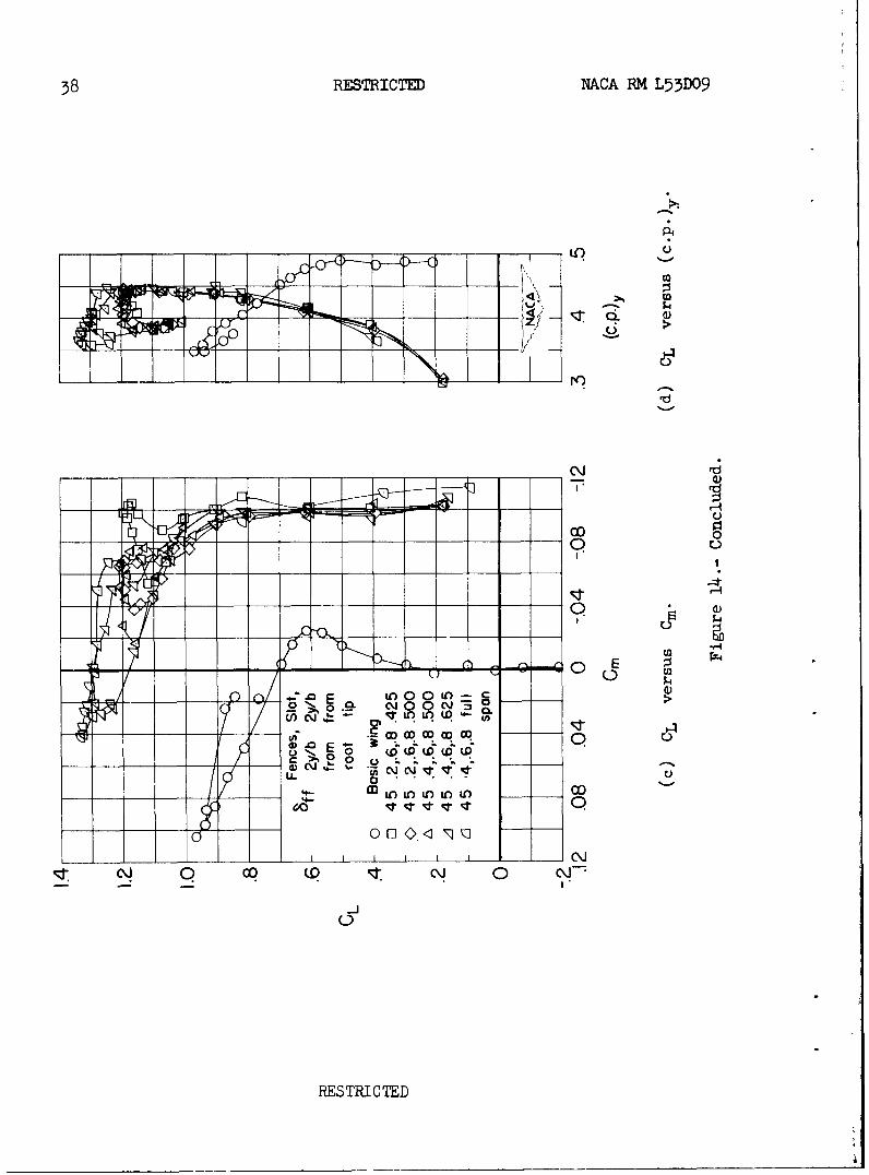
An index of the test conditions and the configurations tested isgiven in table I and the results of the tests are presented in figures 4to 14. A summary of the effect on ACLmax and ACLa=o of Fowler flap
location, Fowler flap and plain-flap deflections, and Fowler flapdeflections tested in combination with various plain-flap deflectionsis presented in figures 15, 16, and 17, respectively. The effect ofslat span on ALmax for the basic wing and flapped wing with fences
is illustrated in figure 18.
Although the particular slat-wing combination tested herein maynot be an optimum arrangement, because of the use of the unmodifiedwing leading edge, it is believed that the arrangement is of sufficientaerodynamic efficiency to illustrate the general effects which may beobtained by employing a slat in conjunction with this wing.
In figure 17(a) the results obtained with the Fowler flap deflected
300 in combination with various plain-flap deflections are compared with
predicted values which were obtained by simply adding the lift increasesproduced by the plain flap alone (fig. 16) to the increments due todeflecting the Fowler flap (plain flap neutral, fig. 15).
At this point it is probably appropriate to note again that theFowler flap angle relative to the wing chord line is altered when theplain flap is deflected, since the Fowler flap is rigidly attached tothe plain flap. Thus, in predicting the curves of figure 17(a) by theuse of the data in figure 16, as discussed above, the ACLmax and
bCId=0 values used were for the corresponding values of 5ff. rather
than 5ff.
RESTRICTED

NACA RM L53D09 RESTRICTED 7
The effect on 6CLmax and bCL =o of varying the plain-flapv =h=deflection for Bff = 500, -- = 0.95, and h 0.01250 and for
cc cC C
Inasmuch as the hinge locations were different for the two deflections,this difference must be taken into account before the effect of deflec-tion of the Fowler flap can be determined. Therefore, the data forBff = 300 , at -r = 1.0 and hi 0.00625, were predicted from the
C c
data of figure 16 by adding the appropriate values of WImaa
and LCLa=o for the corresponding deflections 5ff' and bpf. Since
the results of figure 4 show only small differences in the aerodynamiccharacteristics in the range of Reynolds numbers tested, the effect onthis comparison (fig. 17(b)) of the difference in the two test Reynoldsnumbers is probably of no significance.
SvtARY OF RESULTS
The main effort of this investigation has been directed towarddetermining the influence on the lift effectiveness of the Fowler flapof such flap-positioning parameters as chordwise location, gap size,and deflection angle. Although no detailed analysis has been made ofthe results presented, a few of the more significant trends of the liftcharacteristics which can be readily noted from the data are as follows:
1. For the range of Fowler flap locations tested herein, the morerearward positions produced the greater values of Amax and -M.
(fig. 15(a)).
2. At the larger Fowler flap deflections (8ff = 450), gap size hasa significant effect on LC=,O (fig. 15(b)).
5. The lift increments produced by the Fowler flap located nearthe trailing edge of a plain flap (an arrangement that gives a double-cambered surface at the rear of the wing) can be readily predicted bysimply adding the individual lift effects of each flap.
4. When the Fowler flap was deflected, the use of leading-edgestall-control devices of 0.5 semispan or longer produced very signifi-cant increases in bCLmax (fig. 18).
RESTRICTED

8 RESTRICTED NACA RM L55D09
One of the aims of this investigation, was to obtain satisfactorylongitudinal stability at high lift coefficients. The particular com-bination of sweep, aspect ratio, and airfoil thickness used in theinvestigation, however, resulted in a severe longitudinal-stabilityproblem. Although none of the test arrangements investigated hereinprovided satisfactory stability throughout the lift range, several ofthe fence and slat configurations tested increased the value of thelift coefficient at which the flapped wing first exhibited suddenlongitudinal instability and, consequently, resulted in usable liftcoefficients through a larger angle-of-attack range. It is probablethat for the wing investigated, as was the case for a wing of similarsweep but higher aspect ratio (ref. 7), satisfactory longitudinalstability can be obtained from certain limited combinations of leading-edge-slat and trailing-edge-flap spans.
Langley Aeronautical Laboratory,National Advisory Committee for Aeronautics,
Langley Field, Va.
RESTRICTED

RACA RM L53D09 RESTRICTED 9
REFERENCES
1. Lipson, Stanley, and Barnett, U. Reed, Jr.: Force and PressureInvestigation at Large Scale of a 490 Sweptback Semispan WingHaving NACA 65A006 Sections and Equipped With Various SlatArrangements. NACA RM L51K26, 1952.
2. Barnett, U. Reed, Jr., and Lipson, Stanley: Effects of SeveralHigh-Lift and Stall-Control Devices on. the Aerodynamic Charac-teristics of a Semispan 490 Sweptback Wing. NACA RM L52D17a,1952.
3. Lipson, Stanley, and Barnett, U. Reed, Jr.: Comparison of Semi-dpan and Full-Span Tests of a 47.50 Sweptback Wing With Synmetri-cal Circular-Arc Sections and Having Drooped-Nose Flaps, Trailing-Edge Flaps, and Ailerons. NACA RM L51H15, 1951.
4. Gottlieb, Stanley M.: Two-Dimensional Wind-Tunnel Investigationof Two NACA 6-Series Airfoils With Leading-Edge Slats. NACARM L8222, 1949.
5. Sivells, James C., and Salmi, Rachel M. : Jet-Boundary Correctionsfor Complete and Semispan Swept Wings in Closed Circular Wind
Tunnels. NACA TN 2454, 1951.
6. Katzoff, S., and Hannah, Margery E. : Calculation of Tunnel-InducedUpwash Velocities for Swept and Yawed Wings. NACA TN 1748, 1948.
7. Salmi, Reino J.: Effects of Leading-Edge Devices and Trailing-EdgeFlaps on Longitudinal Characteristics of Two 47.70 Sweptback Wings
of Aspect Ratios 5.1 and 6.0 at a Reynolds Number of 6.0 x 106.NACA RM L50F20, 1950.
RESTRICTED

10 RESTRICTED NACA RM L53D09
TABLE I .- INDEX OF TEST CONDITIONS AND CONFIGURATIONS
-6 Fowler flap position FigureR X 10 h/c' v/c' f Remarks number
I4.14Fowler flap off 0 Basic wing 4
6.1
0l0
6.1 Fowler flap off 520
30
Fowler flap off 0 Basic wing
0.90 0.00625
.95 .012500.1 06.02500 30
1.00 .01250__________1 =____ 0625
Fowler flap off 0 Basic wing
.90 .00625
.95 .012506.1.02500 45 0 7
1.00 .01250
.00625
Fowler flap off 0 Basic wing
0
10
6.1 .95 .01250 30 15 8
20
3045 0
Fowler flap off 0 Basic wing
6.1 - 0 9i.00 .00625 40
45
Fowler flap off 0 Basic wing
6.1 1.00 .00625 45 0 Plain flap undersurface 0faired and sealed
4.4 0Fowler flap off 0 Basic wing
0
54.4 11
1.00 .00625 45 10
15
RESTRICTED

NACA RM L53D09 RESTRICTED 11
TABLE I .- INDEX OF TEST CONDITIONS AND CONFIGURATIONS - Concluded
R l16
Fowler flap position Fence locations, Slat span, 2y/b Remarks Figure• j 6cf 2y/b from root from tip number
Fowler flap off 0 Off Basic wing
Off
4.4 0.4, 0.8 Off 121.00 0.00625 45 0 Full-chord fences
0.6, 0.8
0.4, 0.6, 0.8
Fowler flap off 0 Off Off Basic wing
Partial-chord fences0.575 at ?Z= 0.6, 0.8
b
Partial-chord fences
at 2 = 0.8 134.4 1.00 .00625 45 0 0.6, 0.8
.425 Partial-chord fences
.o at !K = 0.6, 0.8b
From 0.425 outboard Full-chord fencesto 1.000 inboard
Fowler flap off 0 Off Off Basic wing
.4250.2, 0.6, 0.8 Partial-chord fences
.500 at 2L = 0.6, 0.8
4.4 b 141.00 .00625 45 0 .500
0.4, 0.6, 0.8 .6Partial-chord fencesat L- = 0.4, 0.6,
1.000 0.8
'Wherever the slat span was of sufficient length to intersect the leading edge of a full-chord fence, the fencewas cut to a partial-chord fence. (See fig. 2(b).) NCA_-
RESTRICTED

12 REST'UCT NACA RM L53D09
6r 0 5
U))
(0Z0l 0 to
00
4-
4-4
U')U
4-N<0
0
U*U)
00 10) U2.r
0)
ot
/r /
(069,' /q r4,,
RESrMI C TED

NACA RM L53D09 RESTRICTE 13
L P
0*0LL
CILD
0.0
0 0.
00
4r 4-H4
0
H
Sa4L9,.
lbC
RESTRICTH

14RESTRICTED NACA RM L53D09
4-- Oo)
a -
00a)
0.
0-4-
0) 0
4-0
090' a)
B ~-
00
c~-p
RESTRICTE

NACA RM L55D09 RESTRICTED 15
'3.
nj
-H
P4 c
4-)'
F-4 O (v
PLESTRI CTED

16 RESTRICE NACA RM L53DC9
(b) Close-up of undersurface.
L729
Figure 3.- Concluded.-
RESTRICTED

CNACA RM L53D09 RESTRICTED 17
0
(D
4)
-)'
0r 0
o
00 g
cd -
CI20
.ib 4
0l l
0- -4r
-RESTRICTE

18 RESTRICTED NACA RM L53D09
C,
00
000co~
00
_ _ _ _ _ _ _ _ _ _ _ _ _ _ _ _ _ C-
00 (DI
RESTRICTE

NACA RM L53D09 RESTRICTED 19
f rv G ll~l
z4I. LC
cC,)
x-
JrI-TP 0 % ~- - ~
N00
*-4 C)
OL 00 0 c ~e 4-4 i
c~~j
M P4
-4 0 W)0.) Cl)
C,, C.4 4)
0
c',j 0 co (.0 c~1 0 c~j'
RESTRICTED

20 RESTRICTD NACA RM L53D09
rd
I0
00
0000
0 0
cl~i 0 CC w q 1~ 0 04
RESTRICTED

NPLCA RM L53D09 RESTRICTD 21
_ CM
4 Lo
to
S0I
0
i00000
0 04
-u~~~~4 Ca o0o -- c"ICmc MO) OO W E
0 d -' 0
01-1 Q Q 0~0-J-to0r
RESTRICTEDc

22 RESTRICTED NACA RM L53D09
LO4
00
0
c J Q cCJ o\
i-JC-Q)
0 0T ICLo

NACA RM L53D09 RESTRICTD 23
(Dn
-4
r40
0 II
rr ) a.INP 0
0
CC.)
A22J 01
co r -4(o 0 0W .00. 0 C):
p 00
4-1
r14
C 0 0 c' 0
-J0
RESTRICTED

24 RESTRICTD NACA RM L53D09
CL
000
_U - ----- ~o
00
_~c - 00-- 0- U
..c 0 -z c'J 0-j oo
d0
RESTtoI0T0D0) 0) 0 0 0

NACA RM L53D09 RESTRICTED 25
0 P4
0 rA(UC~) -O~
I W)
cojo 00 0
0 4
0 4 4-) 0
cc .
m 0 14
0C cd c
00
RESTRICTED

26 RESTRICTEO NACA RM L53DO9
LO4
CL.
110
rd
CM.
coo
QT C a);
E1
ma)
__ co
-j~
P.ESTRICTED

NACA RM L53D09 RESTRICTM 27
_ ) (0
0 cd
0 A
4) H
rD~-4 (M
to 0
0
___ __ -4--
SCa 0
-7'rr p 4) H-
Ea owrIr4I
__J 0_ 0 0 'wO
7I
_ _ _2 1Q)
RESTRICTED

28 RESTRICTED NACA RM L53D09
___ ______ C.
LO)
0r
0V
L))
Q__ C_ 00 0
cco I ccJ 0
RESTRICTED

NACA RM L53D09 RESTRICTE 29
C-) 0P.4 -4 0f
0
P4 c
-~ I) 0
0d 0
__ 4a
C- 4 -4
0 1-1
rz4
LC C0 CO M, CJ 0q
000
RESTRICTE

30 RESTRICTD NA.CA HM L53D09
AA
cr- -- 0
0
00
0 0
I I C
__j OP _P 0~ O
RESTRICTE

NACA RM L53D09 RESTRICTD 31
.H 0
CC
___ U
-7 Cc
00 0c:-j 0 0
C\J) & 1)
G_ 0_ O 0 XOr 1
0
to o c4-f))
0-i
01\ W~ 0 _A:t
a) P4 N'
cd H- 0)11
4.-4
00
RESTRICTED

32 RESTRICTED NACA RM L53D09
00
CL.
CO 0)
0 0l0<1I
I IT 0)j
0\ 0 C.)cj ~
RETICE

NACA RM L53D09 RESTRICTE 33
----- --- ~ --- o
- (uzc
-~ K 0da
_ _00
__ - ---- C) 0
C\P op OP L
Lo U. U-) --) r) 0
0)
i77t r 0p 0)--
a) 4-)A
COA 0 0
0)I
IU43
CNJ~ o ~
RESTRICTE

34 RESTRICTED NACA RM L53D09
)OWN)
rd
-0 0
oW. 4
E #
L 0 0 0
c j 0 33
0 OLO U) '
c 0 00 (0 C\j 0 CJ
RESTRICTED

NACA RM L53D09 RESTRICTED 5
- ------------ c'
Lo U- L LO o
-f j W) r4I) a'3 a, , '1 LO 0
i J. N
It-1 ' )LOt --- j Ea Ena. LL
00,n
_ ,0 4- 0-
-
N~ 0 0
_ 0)
4 40
0 Ua)0
* T4 0
N4- (0 C0) .-
__ o to *-0
f0
cN WI C.0 11 0
-JL
RESTRICTED

36RESTRICTM NAXJA RM L53D09
-0 P4
z
co 0
00
LO U) 0
-I--~ - cjto .
Q~~~~ 0 'J
OD(900 O -
FLS5T TED,

NACA RM L53D09 RESTICTEDl 37
to
c ooC) x
to 0
-H
00
cdr4
CO ~ a; i w
0 fl
Lr) CH
EI LO
0 C~i 3 -4CL 8 8 U P
--) -- 0P
C~J Q fl (9C'.c-J,O0CHt
RESTRcTE
38 RESTRICTD NPCA RM L53D09
P4
6 ~ r
7 0rd
000 0
____ ___ ___ _ I I I
m~ E -0 (D CJ
o-0-C wqq
RESRITE

NACA RM L53D09 RESTRICTED 39
t 1s
z 0o o 0
N'N
M 040 0
. g --- 0 -oH
oor~ e-"Q0 Cc
000
, -0
0- -o0
LnO
p O0)
OH0 0
0
H °o
0 a
o o
0~~%u -P 0 0
-H
0E 0TICE
a 0
0 0I
RESTRICTE

40 RESTRICTED NACA RM L53D09
(00
o ta ECH
0
o co
'1 p4
_ 0,
(rH
4- 04-
00 0ci
00
00
0- x-__(
RES-RICT-

NACA RM L53D09 RESTRICTE 41
0l
E
_ _ _ 0 * 4-)
.0-~ 10, 0 0 0
-- u 4- 4-))
~OoNN
__0 _ 0D d4-
(0 U
> ~1 .*C
0 60 0
60 %._ -
0 -0 0
- -o
0 0
4- r-i-In"-4 0
o4- II 4
C (0 N 4 P4
000- - P
In 0'uEd- P4
C) C)j U)q
(D, <8cm0 rd. 010 P4
Sr - 00 12 40 Lc UL
0 -o -JJU'
- N
00 4-)' (0 Q
rd
000
0RESTR4-) U
II

42RESTRICTM NACA RM L53DO9
__ 0
c12
4-4
0
CN
04- 4-)
Jo W
-0 0
(D 4- 4-(DU- 0
_fU') -O
> 000 co
0 0
900
00<0
0E
RESTRICTED NACA-Lungly - 6-5-U - 335
C4 I4 z .4 z
i L toa
E-'-4 4' - 0) t
~~Ukw~ ed
ER ~w
.4 m -4 m ,
00) 00 ~0 2.4.
5. 2 u<4-F z boe'n Z
E1.
-- 1C 44 .:
wv~ i * ;;-005 C) . 8it 2 2-
.4 ; 0 to'AD I IwoW 1 - ,,-
AS 41- W 0 U W, m5Z6 r4WU 0. E-44 0 a w ra cc
U l£
P4 a!1