liioiitd/£ . atrllrtlml, ri: pi)rt
TRANSCRIPT

ARR July 1949
b
NATIONAL ADVISORY COMMITTEE FOR AERONAUTICS
J P L LIBRARY
liioiitd/£ .
AtrllRTlMl, RI: Pi)RTORICa_NALLY ISSUED
July 19h2 as
Advance Restricted Report
WIND-TUNNEL STUDY OF THE EFFECTS OF PROPELLER 0PE_ATION
u_ND FLAP DEFLECTION ON THE PITCHING MOMENTS _D
ELEVATOR HINGE MOM_NTS OF A SINGLE-_GINE
PURSUIT-TYPE AIRPLANE
By H. R. Pass
Langley Memorial Aeronautical Laboratory
Langley Field, Va.
L
...... Y
WASHINGTON
NACA WARTIME REPORTS are reprintsof papers originallyIssued toprovide rapid distributionofadvance research resultstoan authorizedgroup requiringthem for the war effort. They were pre-viouslyheld under a security statusbut are now unclassified. Some ofthese reports were not tech-
nlcallyedited. All have been reproduced without change inorder toexpedite general distribution.
L- hll

41,

NATIONAL ADVISORY COMMITTEE FOR AERONAUTICS
ADVLNCE RESTRICTED REPORT
!
W!_TD-TUI_NEL STUDY OF THE EFFECTS 0Y FROPELLER 0PERATI0_!
A_TD FLAP DEFLECTION ON TI_E PITC_IiNG MOMEI_TS AND
ELEVATOR HINGE MOMENTS OF A $1_GLE-ENG!NE
PURSUIT- TYP_ AIRPLA_E
P Y H. R. Pass
SUMMARY
A mock-up of a pursuit s.irple, ne hc, s been tested in
the _ACA full-scale wind tunnel and the effects of pro-
peller operation and flap deflection on the aerodynsmlc
che, racteristics of the wing-fuselage combination and ofthe horizontal tall have been determined. The results
of these tests havo been compared _ith thG results of
previous tests and with available theori_s and. in general,
satisfactory comparisons hove been obtain_,d. These re-
sults have also bean used to develop empirical procedures _
for det_rmining the effect of propcll_r operation on the
llft and on the pitc}_ing moments of a fls_pped _ing and to
evaluate e_pirical fs,cto_'s for calcul_ting th_ down_r_sh
an,_<_s at the t c,il ",:_th the propeller oporatin_. The
general _pplics,_ility of the-so empiricisK_s has not been
determined. The elc_vator hin_-moment charact_?ristics
have also been detormine_ from _ests on the mock-up and
indicat, _. the Inadcqus.cy of av_ilable data on the hinge-
moment p_,ramotors. The procod_r_ for _alculating s_ick
forces from _ind,tunncl d_ta h_s b_en outlined.
•INTRODUCTION
Extensive lonzitudinel-stability and control tests
have been con_ucte_i in the NACA full-scale wind tunnel on
a mock-up of a _ursuit airplane. The res_].ts have been
analyzed to evaluate the variou_ factors that effect the
pitcLing moments of the airplane and the _tlck forces.
A comparison of th_se results with the results of previous

work indicates the limitations of available informationfor preliminary design purposes.
The study is considered in four parts. In part I,the effect of the fusel,_ge on the wing characteristics isconsidered. Part II is a study of the effect of the tailon the pitching mo_nent and includes an estimate of theisolaLted tail characteristics and of the effective down-wash and velocity acting on the tail. Surveys of airflo,_ in the region of the tail are also included. Theresvlts of parts i and II are combined in part Ill inwhich the pitching-moment curves for the complete airplaneare developed. Part IV deals with the elevator free-floating and stlck-force characteristics of the airplaneand indicates the interdependence of the various factorspreviously considered, The effects of flap deflectionand propeller operation arc considered in all sections,
SY_4BOLS
W
CL
CD
CN
M
Cm
Che
Cp
C m
c%
P
T
gross weight
llft coefficient
drag coefficient
normal-force coefficient
pitching moment
pitching-moment coefficient
elevator hinge-moment coefficient
power coefficient / P )\pn 3 05
section pitchlng-moment coefficient
section lift coefficient
power input to propeller
axial propeller thrust
hinge momcnt)qSec" e

L
--= = ;
F
D
V
11
P
T c
CT
q
qo
(q/_o) _ff
(q/qo)av
(<U%) aa
£
ceff
S
stick force
propeller diameter
airspeed
propeller blade.angle
propeller rotational _pe_d, revolutions per
second; also, dist_ncs from c ent,_r of gravity
forwar& to a_._odynamlc center of wing-fuselage
combination (measured parallel to thrust llne)
propul_ive efflclency
air dehsity
r T hthrust coefficient _pVeDe #
absolute t_ru_t coefficient
local dync, mlc 1_ressure (&eV_h\:" Y
free-_troam dynamic pressure
effective dynamic-pressurefactor, ratio of
measured dCm/dee to value corresponding
to free-_tream dynamic pressure at _ail
ratio of average dynamic pressure at tail,
as founl from air-flow surveys, to free-
stream dy_amic pressure; the average is
weighted according to chord
ratio of arithmetical-average dynamic pressure
at tail, as found from air-flow surveys, to
fr_o-stream dy_smic pressure
local dcwnws_sh an_._le
effective downwa:_h angle at tail, as found by
comparison of pitching moments with various
tall settings and without tail

_v
S
_0
S
b
C
C
_2
_3
c_t
i t
8
T
A
A t
average downwash engS.e at tail, as found from
_ir-flow _urveys; the average is weighted.
according to both chord and local dynamic
pressure
the arithmetical average of downwash anglo
across tail, as found from _ir-flcw surveys
velocity-increment factor back of propeller
di_k
ii _ s!_t-curv_ ope for infiuite _sloeot rs.tio
span
chord
moan geometric chord
distance from propeller disk to center of
gravity of nirpln, no (me_sured pmr_llel
to thrust line)
dis._a_e fr center _f gravity t_ elevator
hinge line (messured parallel to thrust
line)
distance from trailing edge of root chord to
el_vator hinge line (measured parallel to
thrust line)
angle cf attack ef thrust axis
angle of attack of tail
angle of tail setting relative to thrust axis
control-surface deflection
rel_tive elevator effectiveness factor
empirical factor in formula for 8etermining
increase in ].ift due to slipstream velocity
theoretic_l factor used in determining .increase
in tal-'_ lift _ue to slipstrcam

m U
mm=
r
L
r-g
r-W
_s stick length
u,v hinge-moment part, motors
A¢I, A¢ 2 empirical corrections u_ed
downwmsh s ngles at tail
v&lu_ _
A denotes chan_,_c, usually due
operation
Subscripts:
o propeller-remove_
p propeller-operating
P propeller
w wing
f flmp
f + w wlng-fuselag_
fw flapped wing
t horizontal tail
A airplsnc
e elevator, beck of
i portion immersed
Is isol_ted
s slipstre_m
b balance
tr trim
ff free floating
_.c. aerodynamic c_nter
cal calculated
condition
condition
combinstion
hing_
in slip, s tream
to obtain effective
from c_Iculated
to propeller

TESTS
The tests were m_de in the NACA full-scale windtunnel (reference i). The usual wind-tunnel correctionsto the anglo of attack and the drag, obtained from refer-ence 2, and the additional correction dun to the "blockingeffect" (reference 8) have bee%_appli:_d to the experimentaldata. The pitching moments h_ve not been corrected for thewind-tunnel interference on tue downwash at the tail (refer-ence 4); the interference was, however, considered in thediscussion of the results.
The mock-up represented a single-engine, tractor-type,low-midwing airplane design (fig. 1). All parts of thecooling system snd the carburetor scoop were removed forthe tests. The elevator _,ras controllable from the cock-pit during the runs. The wing flap was of the slottedtype and was deflected 40o for _ll flap-deflected con-ditions. A 25-horsepower electric motor installed inthe mock-up oporated a Curtiss electric controllable-pitch propeller whose blade-angle setting could be con-trolled end detc_rminsd during the runs.
The force tests consisted of m_asurements of lift,drag, and pitching moment on the mock-up _,_ithout the tail
i %surfaces and _Tith tn_. tail surfaces with 7e_rlous settings
of the stabilizc_r and the elevator. For the elevator-
effectiven_ss and h inge-momeut tests nn operator in the
cockpit _anipulated the elevator control stick and. using
a conventional i_ACA control-f0rcs indicator, m_ssured the
stick forces. All tests included the effects of flap
deflection and propcll,J_r operation. The propeller char-
acteristic_ (fig. 2) were det_:rmined from propulsive-
efficiency tests of the complete mock-up. The accuracy
of the stabilizer and elev2,tor s_ttings _,_as estimated to
be within _-0.20 °. In the ano, lysis of the data, extensive
cross fairing was performed.
With the horizontal and vertical tails removed, air-
flow surveys _ere made in the region of the tail. The
surveys were made by means of a survey r_ck consisting
of 15 pitch-ya,_ tubes,
At each angle of attack: the propeller was operated
over a range of blade _.ng](_s s_nd advance-diameter ratios
to obtain _ rs.nge of thru._t coefficients. AIs, rge range
i

__=
L
_-r_
r-4
of possible operating conditions _ras thereby covered;
the greater part of the measurements, however, were madefor conditions that approximated full-power operation
of the mock-up as 9. typical pursuit airpl_:_ne _,ith 1000
brake horsepo_:rer (fig. 3). Propeller charts for a nearly
similar propeller were used for the preliminary calcu-lations. In order to obtain desired values of V/nD,
the tunnel speed was varies between _0 and 60 miles per
hour.
As previously noted in reference 5, it was found
that the lift and the pitching moments were relatively
unaffected by reasonable variations of the propeller
blade angle _ if the same thrust coefficient Tc
was maintained° Th_ results of reference 5 indicate
that, for the cases with flaps retracted, the use of
the lift coefficient for the propeller-removed condition
in determining th_ propeller-operating conditions is
barely satisfactory as a first approximation. For the
cases with flaps deflected, however, this procedure is
entirely unsatisfactory and the effect of propeller
oper_'.tion on the lift must be estimated. The propeller-
operating conditions must then be recalcul_:_ted, the
new lift coefficient being used.
I. WING-FUSELAGE COMB I_TAT i0_T
The addition of a fuselage to an isolated wing gen-
erally shifts the aerodynamic center forward (reference 6);
the lift and the pitching moments for a conventional
combination, however, are practics lly the same as those
of the isolated _ling (the pitching moments being taken
about the corre_pondlng aerodynamic centers). The wing
and the fuselage can therefore be conveniently treated
as a unit.
Lif t-Cu1've Slope
Lift, drag, and pitching-moment curves for the tail-
less mock-up with flaps both retracted end deflected are
presented in figure 4, For the retract_d flap the ex-
perimental slope of the lift curve is 0.071 per degree.
The slope for thu isolated wing as calculated by the
met!ods of reference 7, estimated section characteristics
being used, is 0.073 per degree. The results of previous
tests of similar wing-fusel3ge combinations (reference 6)

8
also show practically negligible _ffect of the fuselageon th_ slope of the wing lift curve.
The experimental slope of the lift curve for thecase with flaps deflected is 0.0?2 per degree. Reference8 also indicates only a slight change, in general, in theslope of the lift curve due to flap deflection.
Aerodynamic-Center Location
The experimental aerodynamic-center locations havebeen determined for the wing-fuselsge combination fromfigure 4 following the methods of refer_once 9.
2k_ttracted flaos.- With the flaps retracted the aoro-
d:Tn_v_ic center is 0.32 foot in front of and 0.89 foot be-
low th_ centaur of gravity. The calculated locetion for
the wing s lone, by reference 7, is O.10 foot in front of
the center of gravity. The forbear@ shift of the aero-
dynamic center caused by th_ fuselage is, therefore,
&n = 0.040_w, which is in approxim_%te agreement with the
experim,_ntal results of reference 5. This value is also
in excellent s gr_emont _Tith the t_eoretical value of
0.04Z-g w for An ca_ulated__ from the formu_ _s_2 glven" inr_f ercnce i0.
The vertical location of the aerodynamic center is
primarily a function of the drcg characteristics of the
mock-up.
_eflected fl_- The position of the aerodyns_mic
center for the wing-fuselage combin_tion _ith flaps de-
flected is 0.60 foot in front of end 1.55 feet below the
center of gr_vity. This position i_ considerably forward
of the location with retraoted flaps. The theory of re-
ference l0 indicates that p_rt of this additional forward
shift is probs_bly due to an increm_e in the effect of
the fuselage when the flsps are deflected. The further
downward movement of the aerodynsmic center is due to
the increased _ing drag.
Effect o_ Fropoller 0pers_.tion
Propeller op,_r_ttion hs,s t_m_O separate effects on the
lift and the pitching moments of the wing-fuselage com-
bination, The fire, t, des'_-_nated the direct effect, s rises

-3
9
from the forces on the propeller itself _nd may beestimated from the results of tests of isol2ted pro-pellers in yaw. The second, designated the slipstreameffect, results from the increased velocity and thechan_:e in the direction of the air flow at that partof the wing immersed in the slipstream.
_etractedfla_- The experimental effect of propel-ler operation _t v_rious angles of attack and thrust con-ditions on the lift and on the pitching moments of thewing-fuselage combination with flaps retracted are pre-sented in fi_Ires _ and 6, respectively. For comparison,the effects calculated by the zethods of reference 5 arealso shown in th_ figures. The agr,_ement bet_vecn the ex-perimental and the calculate& lift values is consideredsatisfactory. The agreement for the values of pitchingmoment, however, although satisfactory, is not quite sogood as for the lift values; the effects of the slipstreamon the wing and the fuselage pitching moments, which haveb2en neglected in reference 5, may possibly account forpart of the discrepancy.
Deflected flaps.- The experimental off,._'cts of pro-
poller operation on the 1}ft and the pitching moments of
the w_ng-fuselage combination w_th deflected flops are
presented In figures 7 _nd 8, respectively. The lift in-
crements due to propeller operation _re much !erger than
those obtained for the correspon,iing condition with flaps
retractf_.d _n:1. the pronounced .Jiving moments in:licate the
con_iderab]e effect of the sli]}_t_eam on the wing pitching
moments for the fl_p defl_:cted. An attempt ,_as made to
apply the methods of r,_fe]:ence 5, heretofore used only for
uuflapp_._d _iucs , to the present case, in order to indicate,
if possible, the applicability of these methods to flapped
wings. It was found that, except for the nece3s_ty of
changing one parameter, the effect oi_ the lift calculated
by these methods was in reasonably satisfactory agreement
with the experimental results. Those methods are sum-
marized as followers:
The calculated lift values (fig, 7) were obtained from
CLp CL o,_ (1)
= + ACLp + _ L w
where ACLp wa_ determined from the formulas and charts
of reference 5 and

lO
m
w
A CLw Sw o hClo
This formula is similar to the corresponding for_.ula
(reference 5) for the plain _,ing; it was found, however,
that k should be 1.6 in_te_,_d of 1.O. According to ref-
erence ]i, this value indic_tes the _ marked effect of the
slipstream on _he flappe_-wing vortex system. Tho term
Cio is the estimated local llft coefficient, without
slipstream, at the center of the flapped win_ rather than
the average lift coefficient of the _:;ing.
The calculated pitching-moN_cnt coefficients, presented
l_i figure 8, have been oOt_tined by consideration of the
direct effect of t_.e propeller forces and of the slipstream
effect on the win_ pitching moment. The slipstream effect
is much ];Brger than the direct effect of the propeller
forces, as indicated in figure 9, in which the direct effect
ha_ been calculated from the formul_ of reference 5.
The slipstream effect on the wing pitching moment
h_s bccn taken as the sum of two components. The first
coml encnt is due to the _ing-lift increment, which is
assumed to act at the fusclc_gc-wing aerodyne.mic center.
The second, e_nd l:,.rgest, component is the i_c_-ease in the
actual pitching moment of the _ring center sections about
their aerodyn_mic c_;nters. The s_.cond component is a
function of the incre_tse in velocity of the slipstream
and of tl_e imm<_rsed wing area. If it i_ assumed that the
section pitching-moment coefficicnts are not ;_ffectcd by
the slipstream, th_s increment racy be expressed _s follows:
= qo) sw (;)AMa c Cma. c. i i
The factor Cmo.c. is the pitching-moment coefficient of
the flapped sections and i_ assumed constant across the
flapped y,ortion Sfw of the wing aren. It is closely
approxlm_ted, from the data for the propeller removed, _.s
cm = Cm_. Sw&oC. _ C. Sf w

, =-
,-4r-4
ll
Dividing equation (S) by Swqo _w gives
SAC m = c _J.'_i(q/qo I) _'gwi Swi _8 Tcs.c. ma.c. _w Sw - = Cm_.c. Cw Sw
(4)
The final expression for the effect of the slipstream on
the wing pitching moment is
ACmw = Cma, c, cwj____--.--Swi --8Tc + _ ACLwCw Sw _ c"w
(5)
If the effect of the slipstream on the fuselage pitching
moment is neglected, the total c_lculated effect of pro-
peller operation is given by
_=
AC m = ACmp + AC m (6)p vr
The value of gCmp is, as for the condition with flap
retracted, determined by the charts of reference 5.
II. TAIL CONTRIBUTION
The study of the tail contribution to the pitching
moment of th_ airplrne involves consideration of the
isolated-tail parameters and of the effective dynamic
pressures and effective downwash angles at the tail. Thecharacteristics of the isolated tail, although an important
link in the analysis, were not available, because no tests
were mP_de of the tail alone. For purposes of this devel-
opment, these charact_ristics were estimated by analysis
of the data for the propeller removed; methods that havereceived some verification in previous studies (reference
12) were followed. The effective dynamic pressure at the
tail is defined by the elevator effectiveness dCm/d8 e and
is equal to the average local dyn:mic pressure at the tail
for the low-angle propeller-removed conditions but, forthe propeller-operating conditions, it is loss than the
average loce.l dynamic pressure me inly because of the finite
extent of the slipstream. The effective downwash anglo is
z £

12
defined by the tail incidence for which the contribution
of the tail to the pitching moment is zero.
The data on the elevator effectiveness was found to
be in good _grcoment with the theory of reference 5; the
dJ_tm on the downwash angles s_ppeared, in general, to be
less satisfactory and exhibited some apparent inconsist-encies.
As a check on the over-all applicability of the
v:_rious assumptions, empirical factors, and formulas,
the total tail contribution to the Ditching moment has
been calculated with their aid and compared with the
experimental values.
Air-Flow Surveys
Some surveys of air flow in the region of the hori-
zontal tail are presented in figures l0 to 25. ?_ith the
propeller removed, the wing wake is considerably below
the horizontal tail but approaches it ._ith increasing
angle of attack. The fuselage boundary layer is clearly
evident in al _ cases. _'_ith the propeller operatin_o, the
limits of the slipstream and the effects of propeller
rotation are readily determined. As is apparently char-
acteristic for single-en,3in_ _irplanes (references 5 and
12), the slipstream is not circular. The marked increase
in dynamic pressure, especially evident at the h_gh angles
of attack and the large thrust coefficients, on the side
of the downward-moving propell:_r blade hs_s been attributed
to a shifting of the controid of the thrust, as discussed
in reference 1.. The w_ry strong local downwash fields for
the case with flaps deflected should be noted. It should
also be observed that the downtrash :_ngles do not appreci-
ably vory with distance from the elevator hinge line.
All the surveys were evaluated to determine the
avers_ge dynamic pressure and the downwash of the air flow
at the horizontal tail. The results are presented in
table I for the case with flaps retracted and in table II
for the case with flaps deflected. Two different typesl,of avers go arc sho_rn in t_ t_bies. The values with the
are straight _trithm_tic averages, definedsubscript aa
&S
! f btl_(q/qo) .a= dx (7)bt/_

!
r-4
c- bt
bt/_
_,p ¢ dx
-bt/2
13
(8)
The vo.lues with the subscript av ar weighted _ver(o=_s,
th,_ local dyn2mlc pressure being weighted according to
the locus chord _nd the lozal downwssh anglo being
weighted according to both local dynamic pressure _nd
loc _l chord:
bt/s
(qlqo)aV - St '. (q/qo) c dx
- t/_
gaV z_
I
st (q/qo)av
bt/2
_._bt / 2 .
Tables I and II indicate that, in most instance,._, either
_lod may be used to evaluate surveys VTei_;ill.ed surveysme,_ , •
have been used exclusively herein.
Isolated-T%_il Parameters
The isolated-tail parameters _,re the slope of the
normal-force curve dCNt/da t and the relati_ze elev&tor-
effectivenesa factor T. From tests '_Jith the y ropeller
removed and 1_ith the horizontal tall at various settings
(fig. 26) and from the formula
dCi_ t
dc_t
(dCm/dit) Sw _'w
(q/qo)o St _2
(ll)
the average experimental value for dCNt/dG t was found
to be 0.051. (Values of (q/qo)o • _ere taken from Surveys.)
This value is in excellent agreemeat with the value of
0.052 taken from figure 21 of reference 14. The average
value of T, determined in this rc]?ort by the ratio

14
'di is 0.59 and is in excellent agreement witht,the value of 0.58 obtained from figure 26 of reference 14.
It should be mentioned that previous comparisons of
experimental data with figures 21 and 26 of reference 14
hsve not always given such excellent agreements as in-
dicated in the foregoing paragraph.
El@vator Effectiveness and nf_ective Dynamic Pressure
The experimental variation of the elevator effective-n_ss with thrust coefficient with the fl_ps retracted and
with the flaps deflected, is shown in figures 27 and 28,
respectively. With the propeller removed, the elevator
effectiveness is a.gproximately proportional to the average
dynamic pressure at the tail; accordingly, for these con-
ditions, the effective dynamic pressure approximately equals
the average dynamic pressure; that is,
k-J
St 12,(dOm/d6e)o = (dCfTt/dc_t) T (q/qo)o _ --
Sw Cw(12)
The proportionality no longer exists at the higher thrust
coefficients; for such conditions the effective dynamic
pressure is lass than the average found from the surveys
(tables I and I!).
The difference is due mainly to the finite extent
of the slipstream, which is taken into account in the
following equation (simplified from reference 5):
'" ,,<. = (q/qo)o +P
where
jbtistCti kt Ss (dCm_d-_c/i"s
(is)
and bti
stream,
(dCm/d_,,) e
(qlqo)o(i4)
is the span of the tail immersed in the slip-
k t is a function of this immersion and may be

L
L
=_
L_
=
r-_
,--4
A
15
obtained from reference c andt2 ,
:-i + vd +
The effective dynamic pressure is thus given by the
factor
( /qo)e:f =bt i _t i
+
Stk t s s (14a)
For comparison with the experimental results, the
elevator effectiveness was calculated by formula (l[_) for
a range of conditions. Experimental values of (dCm/dae) °
and (q/qo)o were used. For the condition -,rith the flaps
retracted, the surveys and also the computations made by
the methods of reference _. indicate practically complete
immersion of the tail in the slipstream; accordingly, a
value of 2 for k t, as indicated by the analysis of refer-
ence 15, was _sed for these cases. For the condition with
the flaps deflected, the tail immersion was calculated to
vary between 8.5 and 9,0 feet (also approximately verified
by the _urveys), giving an average value of 1.64 for k t
(fig. 41 of reference S). The values of elevator effec-
tiveness calcuio.t,_d with the_e two values of k t are
shown, together with the experimental results, in figures
27 and 28. Satisfactory agreement is observed in beth
CaSe;S,
Down,_ash
As previously mentioned, the average do,.,,nwash at the
tail £_:tv has been evaluated from the air-f!o_,f surveys.
For these same conditions, the effective down_,#ash ¢cff
has been determined from figures _9 and 30. The dis-
agreement between those two experiments,1 downwo$h anglos
(sho,,.;n in figs. [51 and 8_ and in tables I and ii), OSlOO -
cially in the lower angles, has been previously observed,
notably in reference 12. The reasons are uncertain. The
discrepancy, Acl = Ceff - Car, is apparently n'ainly a
function.... of 6av and is in_e_-,;ndentp of flgp deflection
and propeller operation, as shown in figure BS. The curve
of this figure was us,_.d to sufq.ly a downwash-angle correc-

16
tion in the calculations to be gi_zen later; its generalapplicability, however, is obviously very questlon_ble.
Pr___o2elle_rremovedo- The aver uge dew,wash angle ofthe air stream at the tail for all propeller-removed
conditious has been calculated reflecting the methods of
references 16 and i7. The agreement between the calcu-
lated and the experimental average down_ash angles,
indicated in figures 3i _nd S3, is considered satisfactory,
especially for retracted flaps. The calculated values
include %he effects of @ing twist (references 16 and 18)and the wind-tunnel corrections.
p_rov,eller olLLrati_g_.- The _ver<ga downwash at the
tail with the propeller operating has been calculated by
the procedure given in reference 5. Briefly,
f_
whore cp
£p = {wp + Cp = 6ca I
is obtained from charts in r<_.fc_rencc 5 and
g_'Tp "- gW 0
o v!
_0
This rather elementary procc_dure giv_s fairly satiG-
factory checi<s with t_,_e my _ ..... i _ a!ues (t_bles......g_. cxp_r m_nt_l v
I and If). A comp_rison of th:.:s<_ results with the results
of som_ r<_cent _ritish tc_>ts indic,_:_t<_s theft the methods
used giv_ values of Cp that, for the flap-deflected con-
ditions, are too large, l_s_much as _ven small increments
of downwash may consider,_Jbly affect the pitc}_ing moment
contributed by the tail, the discrepancy, At2 = (av- (cal,
was computed _nd plotted as a function of _cai in fig-
ure 34, Different curves were found for the cases with
flaps d_fi_cted and with fl_.ps rctr_ct_d; p_-opeiler
oper_tion, however, had no definite effect. Without fur-
_ _hc gencr._l applicability o_ thether cxparimen_ study, ....
specific values given i_ figure 24 is very question._b!e.

17
,-q
_CI_.
!
III. COM_AR!SON OF CALCULATED WiTH
EXPERIMENTAL PITCHING MOMENTS
Parts I ,-__ndII have summarLzed the available methods
for calculating the pitching mom_ _ _ _-_ __ _n.._s of _.ing!e _no_ne
airpl_mes and have derived the necessary parameters. The
purpose of part Ill is to compare the pitching moments
calcul_,_ted by these methods _rith experimental pitching
moments, in order to show the gen:_ral applicability over
the entire r_nge of operating conditions of parP_meters
dJrived as avLrag_ values from p;_rticul_r sets of tests.
The comparison is first given for the contribution of the
. 0 °)fixed tail (tall-setting ,_ngle, 1 _o; clev,_tor angle,
to the pitching moment; the co_p_.rlson is then o xt0ndod
to the complete mock-up.
Tail Contribution
The experimental tail contribution has been obtained
as the difference between pitching moments of the mock-up
with the tall attached and with the tail removed. The
calculated tail contribution Is obtained by the following
formula:
r-
Om - _ _o.a_._--_. (cl/qo)o+tp = Cl_'i" _/Sw Cw bti-gtiht ssl (_T+it_Ceff> (16)
St
In equation (16)
+ &el + Ace (17)ceff = £cal
in which
Coal obtslned from theory of reference 5
A ¢_ and A Ee
dONt/d_t = 0.051
(q/qo)o
At
s s = + -- T c - 1
f_iven by figv.r_s [_3 and 34
values obtained from surveys
1.64 for flaps extended and 2.0 for
flaps retracted
(zero for propeller removed.)

18
The _xperimental and calculated tail contributionsfor the Gandition with propeller removed are in satisfactoryagreement (figs. 35 and 36). For comparative purposes, thetail contribution has also been cnlcul_ted with experimentalvalues of ceff and with ceff = Ccsl (figs. 35 and 36).
For the propeller-oper_tlng _ondition, the agreementbetween the experimental and th calculated values is notentirely satisfactory (figs. 37 and 38). Calculations ofthe tail contribution using experimental values of Ceff(as obtained from cross plots of tables I and II) are givenin figures 39 and 40. These cclculations indicate that alarge part of the discrepancy in figures 37 _n_d38 occursbecause the methods used in the estimation of the down_ashangles _re inadequate. The discrepancies at low thrustcoefficients for the highest angles of attack may be, atleast partly, attributed to the fact that few experimentaldata in this range were t_ken and to the fact that atzero thrust, with the propeller operating, the conditionsare not quite equivalent to the conditions with the pro-peller removed_ Calculated values of the tail contributionwith Ceff = Coal are also included for comparative pur-poses in figures 39 and 40.
Pitching-Moment Curves for Complete Mock-Up
The experimental and the calculated pitching-momentcurves for the complete mock-u]j are presented in figure 41for the case with retracted fl_ps and in figure 42 for thecase with deflected flaps. The calculated curves wereobtained by the folloving formulas:
For retracted flaps,
= Cm(f _V)o tp mpvmA + + Cm + AC (18)
For deflected flaps,
= + Cm + ACmp + ACre (!9)CmA Cm(f + W)o tp w
Experimental values of Cm(f + w) ° were taken from fig-ure 4; the other terms have been previously evaluated. As

F.
E"E
L
F
ezi_eLed, the" _ 'r.._a:'_nt is not enS_rely _atisfactory;
the disagreement i_ n-erely duc to tile aco,zmulation of
errors incurred in ,_stimating the v_rious co_ponents.
The effect of _t.....landing gsar on the pitching
momcnt is presented in figure _&o As the landing geK_r
is loc_t_:d outside tLe _lipstre_m, the increment of
pitching moment due to the landing gear is probably
unaffected by propeller operation.
IV. ELEVATOR HI_E-MOi_,_SNT CHARACTERISTICS
The stick-force _at_ have teen analyzed with regard
to the hinge-zo_e_t para}_eter_ of the tail surfece, the
elevator free-floating angles, and the stick forces re-
quired to trim the _!rp!ane.
Hinge-Moment Param_ters
Some typical curve_ of the v_,riatiou of hinge-moment
coefficic_nt with angle of elevator deflection s,re shown in
figure 44. Thes_ coefficients are based on free-stream
dynamic pressure. Th_ increase in slope at a value of 8 e
of approximately =_o occurs for all conditions and Is
probably due to the i,rojection of the l_ading edge of the
elevator. _h_ followln Z analysis app]iec only to elevator
angles within the linear rs.nge that, although limited, in-
cludes most fli_ht conditions. Extcnding the m_thods to
the larger elev_:,tor angles th'_t are used in certain ma_
neuv_rs may serve to sho_r no nor< _. than the order of magni-
tude of the hi_,_ge moment. '
The basic equation for hinge moment, taken from
reference 19, is
Ohe = u CNt + v 8 e (_o)
where the coefficients Ohe and CNt are based on the
local dynamic pressure acting _t the tail.. The hinge-
moment parameters u and v should be functions mainly
of the area ratios Se/S t anl Sb/S e.
¥
2O
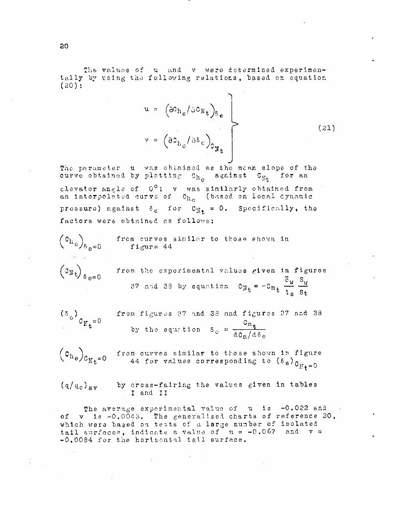
The v¢..uesn_ o+_ u and v were determined experimen-
to,]ly by using the follot Jing relations, based on equation
(2o):
u = (SChe/_CNt)8 " L
The parameter u _,,_,,s obtained as the moan slope of the
curve obtained by plotting Che against C!_Tt for an
elevator an_zle of 0°; v was similarly obtained from
an interpolated curve of Che (based on local dynamic
pressure) against 8 e for CNt = 0. Specifically, the
factors were obtained as follo_?_s:
(21)
(Cho)_ e=O
from curves simil_..r to those sho_,_Jn in
figure 44
oNt) 8 e=0from the experimental values given in figures
_w Sw
37 aud 38 by equ_.tion CNt=-Cat -_12 St
_Nt =0
from figures _7 and 38 and figures 27 and 28
by the eq_1_tion 8c = Cm$dCm/d6e
Che)ONt=0from curves similar to those shown in figure
44 for values corresponding to (Se)oiTt=0
(q/qo)av by cross-fairing the values given in tables
I and I I
The average experimental value of u is -0.022 and
of v is -0.004_. The generalized charts of reference 20,
which were based on tests of a large number of isolated
tail surface_, indicate a v_iue of u = -0.067 and v
-0.0084 for the horizontal tail surface.

21
,-4
--I,%
The disagree'_nt b_tween the values of u and v
determined from the_e tects _nd from the generalized charts
of reference 20 is considerable. References 21 and 22
indicate, however, that details Of elevator plan form and
trailing-edge profile may considerably affect u and v;
other factors, such as _cale effect and the cut-out,
probably affect the pressure distribution ov,_r the eleva-
tor. For those r_a_ons it is not unlikely that charts
ba_ed on a large number of tests with various uncontrolled
factors _¢ould be unsatisfactory for any particular tail.
E
The P_ate of Ch:_nge of Hinge Moment
with Elev:-_tor Deflections
The rate of changa of hi_ge moment with eievator
deflection at co__i:ant angle of attack dChe/d8 e has been• - f i
determined by measuring the slope at 8 e = 0 ° ef curves
similar to those _Xo_n in fidure 44. The experimental
variation of thi_ fsctor with &ngle of attack and with
thrust coefficient is given in figure 45(_) for the case
with retractad flaps end in figure 45(b) for the cs_e
with def!ccted fl:_ps. It should be mentioned that the
hinge-moment coefficient Che is based on free-stream
dynamic pressure.
The formula _o.__- calculating &Che/d8 e may be obtainedby differentiating, equation (_0). If ,the difference between
the effective end the averh_e dynamic pressures at the
tail is neglecterS, ti-e final _--_ression is
F -rdO_'r "+ (2s)] (_m_
where, if desired, (q/q.o)av for the propeller-operatlng
conditions may be calculated from
- -A"
"--'b=(c-;b\qo av o St
For comparison, d" /d8 values ,_ere calculated, experi-ui_ e e
mental values being _]sed for a!l factors, and are also
presente_, in figure 45.

22
The experimental and the calculated valuss are inexcellent agreement for the case with flaps retracted.The agreement, however, is not entirely satisfactory forthe case with flaps deflected; the discrepancy probablyarises from the very marked variation in dynamic pressureacross the elevator span.
Elevator Free-Floating Angle
The elevator free-floating angle is important withregard to stick-free stability characteristics of anairplane. The formula for calculating it is derived bysimultaneously solving equation (20), with Che O, andthe normal-force equation. If the difference betweenthe effective snd the average dynamic pressure at thetail is neglected, the solution is
_.u dC Nt/dat) (C_T + it - Ceff)
8 = - (24)
elf u<dCNt/d_t) • + v
F_F=#
By the substitution into this equation of valuos
previously derived, the elevator free-floating angles were
computed for a number of conditions. The results are
plotted in figure 46, together with experimental values
for the same conditions. There appears to be an almost
constant differenco of about 2o in 6ef f between the two
sets of curves. The discrepancy is possibly due to dis-
symmetry of the tail surface. _,_easurements showed that
the elevator hinge line was slightly above the chord line;it is uncertain, however, whether this error in construc-
tion can account for the entire observed discrepancy.
Stick Forces
The stick forces required to trim the airplane at
any given condition can be determined from these tests
after the corresponding elevator hinge-moment coefficients
have been evaluated. The usual method of determining these
coefficients is to use the basic equation for hinge moment

z
f w!".ere
Chetr(nON t + VSet r \qOJav
etr dgm
d._e
23
(25)
and
dC_t_CYt = _t _ - )(_'T 4- it - c elf + TSetr
Inasmuch a_ the elev_tor free-floating angles an'J the
rates of change of hinge-moment coefficient ,vith elevator
deflection have been experimentally determined (figs. 45and _6), the hinge-moment coefficient at trim has been
obtained more simply from
d e_
Chetr tr elf d8 e
Values of Chctr are precented in figur_s 4? and 48 for
the conditions with flaps retracted and with flaps de-
f!octed, respectively° .Experimental values of CmA and
(dCm/dSe) have been taken from figures 29 and 30 (for
i t = 1,2 °) and figures 27 s.nd 28.
Neg].ecting the effects of friction in the control
system allo-v,rs the stick forces for trim to be calculatedfrom
Ftr =
Ch qo Se _eerr
_s

24
where
W
.._no =.CL_.p
S:.:
or, if the e.irpl_ne is climbing or diving at a largeangle,
Sw Te cos _- C
CLAp
qo =
C SwT;Ap
(_9)
At high angles of attack and large thrust coefficients
equation (PS) gives values of qc the.t are about 12 per-
cent greater th_.n those obtained from equation (29).
Sufficiently accurate values of CLA p may be obtained
from figures 5 and ? _nd values of CD may be obtained
from figure 4.
SUMF.ARY OF __I)TDI_TGS
The follow!r_g remarks, although applying directly
to tLe mock-up tested, iorob_.bl_',possess v_rying degreesof gener_l applicabilit3-o
i. For cs,se_ t,..,ithfl_ps deflected, the propeller-
operatiug co]ditfons c_.nnot be directly determined from
the _.ropeller-rezove_ lift coefflcicnt.
2. The ,'}lope of the lift curve of the tailless
mock-up can bc accurately calculated by the uF_e ofre.ferenees 7 and 8.
3. The forward shift of the aerodynamic center of
the plain vri.:_gce.used by the fuselage can be estimatedby the use of references 6 aud 10.

25
r_
4. The effect of propeller operation on the lift
and on the pitching moment Of the tailless mock-up with
retracted flaps con be satisfactorily estimated from theprocedures given in reference 5.
v
5. _ith the flaps deflected, the increments of llft
due to propeller operation _re much larger than thos_
obtained for the corresponding condition with the flaps
retracted• The differcnc_ is probably due to the effect
of the slipstream on the fl_pped--wing vortex system.
6. Tile slipstream markedly increases the flapped-wing divin Z moment.
7. The isolated-tail param_ter_, as determined from
those tests, compare satisfactori'w _y ith those given bythe _c_larts of reference 14.
8. The effective dynamic pressure at the tail for
the propeller-operating conditions can be accurately
estimated __rom __efercnces 5, ll, and 15.
9. The downwash antics at the tail determined from
different tail settings are not _qual to _hose determined
from air-flow surveys, especially at low angles of attack•
]0. The average downw}_sh angles of {he air flow at
ta. tail, with the propeller removed, can be closely cal-
culated from references 16, 17, and 18.
i! The meth = o alca!c_tin,_• o_s f c _ the propeller-oporatinz down,rash angle _t the tail from reference 5
sre barely satisfactory a_s first apprcximatlons unless
empirical correction factors rare used. It is believed
that most of the discrepancy, for the flap-deflectedcondition, zgj be attributed to th_ methods of calcu-
lating the dow:_w,_sh due to the propeller.
13. Pitching-moment curvets fo," very nearly similar
_.irplanes can prob_bly b_ sati._factoril_ estimated by the
_se of the propeller-remov_d pi%cning moment of the tail-
less airplane and the empirical do_nwmsh correction fe.ctors.
13. The use of the chL_rts of refer?nee 20 for
determining u and v, which are based on the results
of a l_r_e number of te_ts of horizontal tails, is un-
satisfactory. References 21 and 32 indicate tl_at details
of the elevator ple.n form end trailing-edge profile areimportant considerations.

36
14. The climb o7 the d_ve angle of an airp!_ne inpowerad flight should bc_con_idar_d in calculating thefree-_tre_ d._namic p:_ssure.
C01_CLUDI_GREMAPKS
Most of the basic, factors affecting the pitchingmoments and the stir. forces o* _n airpl'_ne can besatisfactorily estiJ__.ted by use of the av_L_lable theoriesr_nd procedures; further s_-stem_tic experiments and relatedtheories, ho_evcr, _re neccss _z_...... ore the do_nwash _t the
_l_er ing rtail with prop_ _ operat m:_y be eli_bly predicted.
Experimental data a_d charts of the hinge-moment parameters
should be used v,,ith ext_'eme care, and du_ consideration
sh __o_._ be given to the vazlous factors, affecting these
pars_meter s.
Langley Memori:_l Aeror_au_leal Labora_tory,
_Tatio_al Advisory Co_n_ittee for Aeronautics,
Lo_n:_ey Field, Ta.

R_FERE_TCES
,-4
r4
--i"
• DeFrance, Smith J. : The }?.A,C,A, Full-Scale %'_rind
[;ur,nei. Rep. No, 459, }TACA, 19 _'_,.)_) ,
_o Silv,:_rsteln, Abe, and White, James A,: Vind-Tunnel
Interference with P_rticular p_eference to 0ff-Ocnter
Positions of the %:ing and to the Do,.,,nwash at the
Tail. Rep. ![o. 547, NACA, 1955_
So Theo_orsen, Ti_eodor3_ and Silverstein, .&be: Experi-
mental Verification of the Theory of _'gind-Tunnel
3oundary In i;erference. Rep. }[o. 478, 17ACA, 1934.
o Silvsrstein, Abe, an_ .Xatzoff, S0 : F.xp'crimental.
Investigation of ",'_Jnd-Tv.nnel Interference on the
Dewnwash behind an Airfoil_ Rep. No. 609, }TACA,
19 370
5o Goett, Harry J,, and Pass, H. R. : Effect of Propeller
' S ,,g!e0per'_tion on tae Pitching Mom,:_nts of i- -EngineI (D" •14onop!anes. NACA .A.C.R._ May _,:_1
o Jacobs, Esstms, n N., and Ward, Kcun,._.th E,: Inter-
ference of Wing s,nd Fuselage fret4 Tests of 209
Combinations in the hToA.C.A. Variable-D_:nsity
Tunnel_ Rcp, No, 540, I,_ICA: 1935,
o Anderson, Raymond F, : D_t rmination of the Charac-
tcri-_tlcs of Tapored Uings, Rcp. No. 572, IfAOA,
1936.
• pearson, Henry A. , and Auderson, Raymond F. ; Calcu-
culation of the Aerodynamic Characteristics of
T.%percd Wings with Partial-Span Flaps. Rep, No.
6_5, NACA, 1939.
¢ Thompson, M. J.: A simp].c _,_.:_t'_odfor Determining the
A:_rodynamlc Center of an Airfoil. Jour. Aero. Sol. ,.
vol. 5, no. 4, Feb. 1938, p]:,. i_8-140.
I0. _,.ulthoFp, H : :_erodyngmic_ of thc .... ei_"e
Ti No. IOY3, 1242.
17.'_.CA
Ii. Smelt, R , _ _ ....... _ of Increase• ,:.n_ Davies, _° : _s_.mation"_o. 1788i_', Lift due to Slipstre_m. 7{. & M. _ .
_r- tisi% A.P..C , 19[:,7_
28
12. Katzoff, S.: Longitudinal C_ability and Controlwith Special Reference to Slipstream Effects.Rep. No. 690, _ACA, 124C.
13.
14.
Olauert, H.: Airplane Pro_eliers. Vol. IV, !i_. L,
_ec. 5, ch. XiI of iercrynamic TheorF, _. F. Du_'ond,
ed., J_!iius Springer (Zerlin), 1935, _p. 351-357.
Silverstein, Abe, and Katzoff, S.: Aerodynamic
Characteristics of Horizontal Tail Surfaces.
Repo _[o. 688, ZfACA, lb40.
15.Koning, C.: Influence o/' bhe Propeller on Other
Parts of the Airplene Struoture, Vol. IV, dlv. M
of Asrodynam_c Thecr_, _. F. Durand, ed., Julius
Springer (3erlin), 12J5, pp. _61-430.
16.Silverstein, Abe, Xatzoff, S., and Builivant, We
Kenneth: Downwa_h and Wake behind Plain and
Flapped Aid'foils, Rep. No. 651, NACA, 1939.
_7.Silverstein, Abe, and _Lzoff, S.: Dcsi_2n Charts
fo _ Predicting Do,ffn_ash ' __ _n_le_ and "_a;:_e Ch_rac-
te1"istics behind Plain and Flappe:.] Wings. Rep.No. 648, NACA, 1989.
Pearson, Henry A., and Jones, Robert T. : Theoretical
Stability _4 Control 0h_racteristics of Wings with
Various Amounts of Taper an& T_Tist. Rep. No. 635,NACA, 193_.
19, Glauert, H. : Th:_oretical ]_.e!ationship_ for an
A_rofoil with Kin_:ed Flap, R. & M. No. 1095,B_'it!sh A.R.C. , 1927.
Pass, H, R.: Analysis of Wind-Tunnel Data on
Directional Stability and Control. T. N. l_o.?75, NACA, 1940.
21. Jones, Robert T., _n& Cohen/ Doris: Determination
of Optimum Plan Forms for Control _mrf_c_s.
E_C.\ RoD. No. 7ZI_ 194_.
22. Jon,_s, _obert T., _n-i Aze-, Milton _., Jr. : Wind-
Tunnel Investi-_'_t_'on_.. of Control-Su_'face Charac-
toristlcs. V - The Use of a Beveled TrailingEdge to Reduce the ;{_nle Moment of a Control
Surface. h_AOA A.P,R., Znrch 194_.

Br4
,4,I
_ACA TABLE I
COMPARISON OF EXPERIMENTAL AND CALCULATED
DOWNWA_ ANGLES FOR MOCK-UP WITH FLAPS RETRACTED
iJI
(deR_
-0.21
_.d. i
6.9110.9 I-2.8 I-2.5 I-1.5 i--I.0 I
I #'% !.K.%2 |
5.11•,a !
,,.#..A !
5.01
5.116.81
6.8i8.9t
I0,7 I14.5l
14.71
r
T c P
(dog)
(a) (a)
(a) (a)
(a) (a)(a) (a)
O _ 41
.02 ! 34
0 56.02 41
.01 55
.04 50
.08 I 29
.03 l 50
.O9 I 37
.16 I 26
.01 26
.II 30
.18 37
.05 26
.51 55
.46 29
.12. 29
&Propeller removed
(q/qo)aa
0,87e_
.84
.82
.94
.93
.93
.99
.87
.97
1.08
.93
1.041.29
.961.09
1.44
1.021.62
2.01
1.17
(q/qo)av
0.84
.79
.81
.79
.91
.92
.90
.96
.8,5
.951.07
.91
1.051.26
.93I. 07
1.46
1.00
1.632.01
1.15
TABLE I I
i
aa av
(deg) ideg)
1.2
2.64.6
6.6.i
.4
.8
.7
1.31.5
2.8
5.i
5.55.2
5.2
5,9
5.]6.8
effl
(deg)l
1.2 2.5 I2.6 4.2 I4.7 5.6 I6.6 6.4 I
.i 1.01
.4 1.1 I9 -I w_ i. .L. , i
6 _ i.,, n
1.3 2.5 I1.4 2.5 12.8 3.5 I3.0 4.b I3.3 4.7 I5.3 6.1 I
4.6 5.5 I
6.0 7.1 I5.4 I 7.] I7.0 7.8 I
i
8._ 9.1 9.9112. i 12.9 12.71
13--_'7 _ 111--!_ 11.7 I
COMPARISON OF EXPERIMENTAL AND CALCULATED
DOWNWASH ANGLES FOR MOCK-UP WITH FLAPS DEFLECTED
ccal "
(deg)
0.9
2.4
4.26.5
-,5
-.3
.2
.2
.9
.91.9
2.6
2.84.5
5.8
5.56.1
6.39.9
14.2
i0.9
_S
uT T c
(deg) (deg)
7.8 (a) (a)
15.1 (&) (a)
5.8 0.22 23
6. I .07 18
7.3 .52 288.6 .34 23
9.6 .35 329.7 .17 18
9.7 .19 18
12.8 .46 2313.1 .21 18
14.2 .58 28
15.0 .08 28
(q/qo)aa
0.88
.83
I. 551.28
I. 921.67
1.60
1.341.36
1.80
1.552.001.03
(q/qo)av
0.85.81
1.61
1.272.03
1.721.66
1.36
1.381,89
i .35
2.011.03
apropeller removed
Iaa _ av
(deg) 1(deg
i0.71 II.
13.0 13.14.01 15.
13.0 12.
16.3 15.
16.6 16.16.6 16.15.2 15.16.3 16.
i 19.4 19.
! 18,0 17.
i 21.4, 20.
_16.55 .... 16 .'
¢ eff i c cal
I l(deg) !(deg)
11. i0.5
13. 14.614 • 12.7
;I 12. n.o16.4
_/l 18". 17.2 16.5I 17.5 17.6
it 15.6 14.
19.3 !21.917.1
20.8 , 24.8
16.4 _ 18L]_


r4",4"!
v
NACA Fi_. 1
F


r-i,.-i
.--.1"!
,--1


,-I,-4
!- ,._i
c !
, \!
\_" ....\
\\
i
\\
\
!
- \
I ...........
Q ' ' 0 _ '
\'h,\\
4-_'_.L.
! ! : :
\
e,l o
ol.
_ _ D_ _
_:_ ,_:
0
•-.a _.j _ _.
._ o
rO
_O /_:._:_!_o_ r:,_j O
I I
"D c _,lglll_O_ 44,n
_,, C)
.....3-__,
-- ,4_-
JI
0
qJ
i __
T'.I _• l,_kg. _


e-I
!
NACA
u
,.*,_!
!I
!
III
I!I
I
I
I
, _I
I o"I
' i.' 5
I II
it "_: ?;0-
\, ,
°r-._0
- °o.-
\i" I,\
\\
\
m
_6I
!!
I
I
I
0I"
0 -
_ "_'_
' _I.
.__


_r--4,-4
I
NACA
ii
ii
i
I"
w
2//I
//
t;;/p!
,-? / /////////Ll//
%
om
\\ -\
\ \
.\- .... _.\•,\ \\ \
\ ,
• \
"..,.\ \
\ \
//
\
\
\
\
\,\ \
-4-
o
I
__i___ t __
\\\
0
°_
I
O3
L=
I


f--I
. -,,,,+!
NA CA oi
T


I
L. _
!
i
=,
! o
|
=::
=
NACA
-- I
r o
S
%
¢
-A e --
ID
_ -3--
II1 -4.--
• I I
Fi?ure I0.-• Concluded
8/
'I-1 I I I I I3 2_ I 0 I P- 3
Disf_nce f'r'om center line, {t,
(e) DynQmic-pressure (R/q) COntOurs,
_igure I0 .--Air flow in She plane c_ +,he
erewtor Iqinge l;ne.
vTew IooKincj forword; O_T,-O Z°_
m _ m
• it
m
w
Ir
I
_. o'; propellerI
/
-,, ]/ .
I
I
removed.
I I I I I_. o 0 I P-
Disl;_ce from oent, er li_ _
(_ Incllna_ion of f,he air $_ream.
4-
4,
I I I I'
rig. _o


I
NACA£-
_l-
C 1.0_
_o
L
O
o
oE
_3-¢--
.9 • 0 o
.0
Fi 9. .
.9
I 1 I I 1 I 1 I I I
Distance from center line_ ft
I
.E
t:: |-
E_- _
o
'_-3--
Ca) Dynamio- pressure (o/'clo) contours.
Fi_ur_ _ I! .--Air flow In the 101_ne of the
elevator hincje line.
View looKir_ forw_rd;c_T,5.1";
6?, 0°; propeller removed.
"x
i
m
\/ / J
I _"
w #
I I I• 5
Figure I1.Concluded
,gCale Of veotor_
Deviation, deg
I I I I I2 I o I R
Distance _'rom center line, ft(b) Inclination of the oir streorn.
I I i 13 4 5 It


r4
i_q
NACA
q-
B
l:: I E
L
> o
.qv
q-
o
I n8 _
,I/) )/ -.'--
.7 II
° •
,@1o0
I 1 I I I I tI o I 2 3 4
DIst_nce from center line, ft
Fig. 12
R]ure
¢c- 1_ I
#3
_= i mI:
_o--
E- ! --
@
I3
_3
#
I I I6 _ 4
Figure I_.. --C_clud_4.
(a)
12.--Air flow in the plone o# _he
elevo_or hinge line.
View IooKin_ l_orw(3r_;(_T, _,_f;
_-_, 0"; propeller removed.
Dynamic-- pressure ('ci/_la) contours,
i
\ \\ \
3 Cal e _Yi_ c_or@o I_ _o
l # o I P..Distance from center line+ _t
/ / 1
# lI ,f /
I I I 13 4 5
(_ lnclirl_ion Of lh_ olr stfellm.


r-I" ,--I
"4!
,4
NACA
E
"_" 3--
(b
_o - __ "__//
o-2--
E
O_E
J_
-;]p--
16
Figure
4_
_w
p t
--4--
I I I I I I I I I I.5 4 ,3 2. I 0 I _. _ 4-
Dmtance from center" fine, f't(0) D)'nom/c--pressure (q/qo) contours.
i3. --A;F flow in the plane 0? the' elevator hir_5_9 4_r?e. View
Ioc_in 9 FOrW_rd'joCr,lO.q _ 4_0; propeller removed.
\\
\\(1) 0--- _
E ' J 1 'o_,. I _ \
0
c5
%
t
/
/ / l _ i 1
/ I I6 5 4
F;9 ure 13.-COmclud¢4,
\ /g
I 1 I I I I• _ 0 I 2 $
Distance from center line_ _'t('b) lmClirnot!On Of" +.he olr StreOr_.
I I I


4
I
NACA
3o>
S
US
I£
I°o )
I I I I I I I I I I I I
Distance from cen_er line_ ft
3--
,E 2_w
R-
0
;_-s--
Ficj ure
-4-
(c_) Dynomic-pressure Cq/qo) contours,
_4.--Air flow rn ghe plane of" the
-5--
I I I6 5
F_gur_ 14,- Concluded,
\ \
/
f
Sc_16 o_" vect.ors
o io ,!o
Deviotion= degI I I I I
Dist, ance from cenger line=f_
(b) I nclina_,ion
3
o£ the air st, re_m.
\
-J-- i-
I I IS 6


I_4
I/aCA pig. 15
_T 4--E-- ,0
.E
_5
I-- .0
O--q-
aa
.8
I I I I I I I I I I I I8 _ "1- 3 P- _ o I & s 4 S 6
Distance £rom center line, ¢t
CO) DynamJc pressure(q/%)contour_.
F c .re 15.--_ir {Io_ in, the _;ur, e cfChe ele'/o,_or b_ngel(ne. View looking
¢LT, 15. I°_ d'f_ 40°; pr'opelier" _emoved.
5 m
4_4_
@
:5 2u
-r--
L
_rw
-3--
-4w
I
I
\
I
/
/
_-orw3_d;
I I I_5 _ 4
Fi jr'F Lf-£ " _ udu
I
..Scaleo{' vector3
0 I0 _0
l DCvi0tion_lI de'I I
2 I 0 IDiSt,3ngC from c8r_er lilge_ ft(b !/nc_Fr, 9t ior_ ¢{+.he e;r 5±regrn
I


L
NAEA
j_ j /I.o
_° ......... k \X[/2,./3 N
-s- hi,_ (=o / \
I.I
I I I I I I I I I I I I I6 _ 4 8 P- I 0 I P_ _1 41, _ 6
Distance from center line, ft
(a) Dynamic-pressure Cq/qo) contours.
Figure 16.- Air flow in 1::he plane o£ ±he elevdtor h_nge line, View Iook;n 9 1%r-
wordldT,--O 2 °" @. C°- %, 0.014.
6 r-- _
c_
G
g
E
g-
I._ -3--
c
/
II• .ip
iF a,
, /
t
_COIe Of v_otors
r_r_r_m
Devi_tion_ dle?i I I _ I I I - I6 _ 4- .3 2. I 0 ! P_
Distance from center line, ft
Figure 16.-Conc}uded (b) fncl;notion of eir _trearn,
I t I I3 4- _ 6


-4I
NACA Fig. 17
£-
ZO-- -
_4-- -7 "
o
E
LO
I I I I I I I I I I f I-$-- _ 5 4 3 & I o I 11 _1 4 l_ 6
Distance from center line, ft
(o) Oyr_ornic-pressure Cq/qo) conLom-s.
Ffgul-e 17.-Air flow inthe iolone or-the elevo-{;or h;ncje Ii'ne VJ'ew Iookin 9 for-
W'or'd]O(T,--0.2°_ dr, 0°) T c, 0.04.
E
_Z
¢
E
o
@
2
-3--
--4--
I I I6 ,5 4
Figure 17.-COl;C!,JJed
J • /
P B
I,3
Scale of vectors
0 I0 _0
D_viotion, deg
w
I I I I I
Distance from center line, ft
(b) Inclina_r/on of the olr _±r-e _'_,.
I I I,'_ 4, .5


-#I
NA6AI w
-l -- ,q _I.7
®
N_ I_
_-_$__
_'ig.Je
),,,,,.,,.,,,,_I. i l.ll
f?Z/
i.l I,! f.o
\\,-oI,E I.!
I / I Is 4 sG
I I I I I IP. ! 0 I I_ 3
Dlotence from oen%er line, ft
2--
di m -w= _
L
t= -#_--
°9.r,,,_
-3--
-4--
DJnamlo-pressure: (ql_lo)contours.
--Air-Flow In "the pfene of" _he
elevcf+.or hln_je line.
View IooKincj ?orword_ e_,
" - t I
I
I I I I
8caler._C_cor3O I 0 P-O
Deviotlon., cIe(:j
I 1 t I I_- I 0 I P
Distance from center line, t't(b) Inclination o£ the oir 3treom.
F_gur6 18. --Concluded.


rdr_
-_t
NA_
4:
c° 1-0
-'_- I I L I I
i0__
I I I i t 1o I P_ 3 4, ,5 i_
Distance from center line, ft
Fi 9. te
I.O
p_
e-
l-
L.-I--
o4.11
}_,,-
Q
Figure
(o) Djvnamic- pressure. ('q/qo) contours.
19. --Air flow In the plone of the
elevator hinge line.
View Iookln_j forward; oLT, 3.1";
df, o'; %, 0.03.
/
I
I4,
G 11
• ,,,,i,
J
w
a
_:ale of vector_
o io £oDeviation, de_!
I I I I I2 I 0 I P-
Distance _'rom center line_ Ct(b) Inollno_ion of the. air .?{._-eam.Fi(jvre Ig . -- Concluded.
i I5
I"
I8


!_q
.8
_.0
Fig:
(a) Ddnamlc-pressure (q/qo) contours.
Figure Zo. --Air flow in the plene'of the
3m
c
c
_'-\ X " \
% % • -.
E
q- \ / JI1)o
{z-2_ fO
g °
elevator hincje line.
View looKin 9 forward; _T, 6.8"I
_f, o'_ T,, o.18.
t
L
/ /
/ // // l
/ s
I I I I6 5 4 3
_cole of' v_ctoFs
o Io 20
D evkltion_ de9
I I I I IE I 0 I l}
Distance £rom center line_ Ct(b) Inclination of" th_ (_tr stream.
Figure 2.0. -- Concluded.
I I I I


Ilq'ACA
+;
,qI I
Lq L J I.Z 1.3
!o
-4--
I I I I6 5 _- 3
F io_ z)
1.4-__13 ';'4
I._-----------
,.,_"°
I I It ¢.. 3
1,3
4 5 6Distance from (:enter line, ft
_Sm
E
c
_o--
Eoq- -| I
g
o
-Sm
-4m
Fiqu('e Zl.
\\ \
t /
(a) O_.ynem¢- pressure . (q/qol Contours.-Air _'low ih _he ploge of t.h6^ elevaf.or hinge, line.
V;eWd,lOol(in 9 ¢or_verd{ (_r, 6.B36f, ; To, 0.11. .
/
.D
't'" /\\ i
- x ",. 1" " " / / 1 1
/ " " _ " / 1 1t - \ , / / i \
ir
/
%
I
\
i /
/
I I I6 5 4
Scale of vectors
o io 20Devidtion_ deg
I I I I I I I I3 _- | o I 2 3 4-
Distonce from center line_ ftCb) Ir_lina{ion Of the. oir S'creom
Fi3ure. 2.1 . -- Concluded.
I


-t-1.,t
Distance from center line, f_,
Ca) Dyno.mic-pressure cq/qo)contours.
Fiqure 2 2.- Airflow in %he plane of the elevator h;ncje line. View t_l_(n_ _rwo_t_c_T_ 10.7 °) 8f, 0°; To, 0.31.
4_ 3--q-
c
C
t- I--
\
_o--_
1EO-1--
t_
-3--
-M--
\
\
\ , \ N \
/ / " _
" \I
\
\
i//
I I
Figure 22.-Concluded.
\
//
4 3
//
11W
t /
1 /_cal_ of vector_
o Io P.O
Deviation, dQgI t 1 I II 0 I P. $
I)tstLanee-from _levator hlt_e IIn_, _td_ Inclination _f _he air s_reorn.
/
\
I I' t4 8 •


-¢
I
Fig23
\ \ ,
\1
\
\
Stole of vectors
F_F_0 IO PO
1 jDeviati°n'J de_ [
I o !
Distance from center Dine, ft
(b) IncJl'no-I:ion Of the oirsfream.
/I/,
dc
C
&z
0 -I_9-
0
I I I I6 .5 4 0
rig,_r_ 2_5.-Concluded.
I I I I3 4- .5 6


=
i
,--I
I ,,f,'_
I-
I I I I I I I I ! l._ I I
II ._ 4 3 I_ I 0 ! I_ ,II + 5 G
Distance ?_m _w_i_er tlt_I, ft
(0) D_/nClm_c-l_ure ('_t%) Contour._.FigureZ4- Air#low in_hee evotor hinge line.View _ook{nq forward; (_T, 15.C_l
6f,4c?lT_,0.0&

i

NACA
\
\
I I I I6 5 4 3
-6--
\k
Figure 25.-C;)ncluded,
.Scole o£ vectors
0 I0 PO
D eviotion, de 9
t I ] I I2 I 0 I
Distance from center line_ £t;
(b) Inchnot_on of "t;he oft streom.
I I t3 4.- S ,6


k_
4
NACA
I-f
I" |.
-6
_. u_l 0
I.
o9
0
I'!!I
I
I
I!
d
/I
.... Jl
i;t t
iT1......i/t
,/
/i t
/w
C) oi _ |,
Ficj_s. 2.7_Z8
_2
' rL _. ,,
_t
w 0
I
b.


1.J
!
@
mP
NACA .2.0
f ==_ _ j 3_
_---_-- __P
.... _ :_-_'____'_-2__ ,.-_...__ .11 --.I0 ...._ _ __.____ _
H ____ "--- _____. ._.
o C_ _,-Z 6 ° _
4 t " °................ _ ..... ¢o ......... _- --
i (t_} Lt l._, , / -'__:i -';'s ! I
e _ l 0 I-- 'I --I r ...... _ " I [ ................ 4
I
................. L-4 .........._ ° .
_=1_ .zs,._zs, 4o ,.,_as
:_° i ('-3 "t • t.2. ° _.__" .oq , ',0% i _"_" .07.- ' I
i /1o I } ! _ --
- 18 9.l_ i i
) ......._I _ ..... * - q• .--_ 7 05 : ,
_/ J;:5- •o_ I i i
- 4 0 4 8 12.. 16 2._
_3- _,ff¢_nt _,_ s_ffm{_ _ fl&ps _a_{4, Doffe4 curve_ &re _rom e#rapol&T_8 wl_es


-- i--Ii-4
I,4
NACA Fi 9, 30
0
0
0


-4"
,,S
NACA
,9
......
,_\
0
,,,,.
°
.#-
I.t'4 __ N
fr
_%'_ e
.-- .._ ed
3_
o_..?
g..a -_E o uo
{.
g
Fi cj,s. 3_:,3.z


i-Ir'-I
I
NACS
I I
.... T---7 £' II
t
r
' 4- !
i I
Q
_4 -.. O
I
I
i
Figs. 35,34-
3
.j
!
,@


I
r
F
NACA
__ _ +
I
:1:1
/ j
j /
f /
//,///
13 " I
:_ __-_ _---
_ _ _
' I I _ /
(/'5 °
o _
,0
, Ii
!
!
It ....
__.J. .........
t"
_g r_
'_. _ --
_ _ ..._ _
, _,_I.
, _"
la_
_i9_. 3_,36

Ib

--t!
NACA FInis.
.I
w, -I.S° _?.o
g-:.i
I
ExI_I_| I I IC_Icul_le.cl,w ifh (_+a_ +aez
-Z -5.0°
Co_°
J
.-_ 8._°
I0.I °
_..---_ 14.fo°
3-/,38
0 .I Z .3 ._- .5Th_sl- coeffi_m_,'F_
,4r----
I,3I_ •
--4 ....
I
• I ....
I IExp • _ i_ e_ta I -
t _'_+"_'+_ ___
0 t .2 .3 .4- ,5 .6
Thr=St co,ff,k,'evT_T=
F_re 38 .- Co_npa_i6c_ oy _xl_rlme,i'_,l &_ calc_l_t_l_o61
i'la_)5dcYlec_fe_l"_g:--l&°.Ca_¢_l_idValwe$/lave_ ob_a_"_eawi"l'h 6ca_+A_,+a_ z.

lIP

,-I
I
NACA
.___
!
:-- ;I+
t
F/ ]
• ',I !i
_ ., 11'_ I_ '
/
! __ ":1_ _kP',''_"i
tl
L_ ....... i .....J I(_ --'. ,.
[ •- _ _
._
p_
0 _
1


'-I-I
!
L
E
F
i1'
F_
L
ii
NACA FicJs. 4-1:,4.2


t-I
"4"I
,.q
N,_C/- _r" _-rigs. 4-3,44
-'_ 1- ,,,_ l r- --I _ IP, ._
....... ,:, .... ,. _ __]o H <l.-c,I "I3 • _ -0-" o
!o _ o _
'::' o _V" _, o o _. o o ' '_' '_ -- "- "
<>_ _ / o_- _. _:_: I I o,.,I J//_. I I I ._/ 1/,_ .,,
I I /I I ; , ._ , '. ! I', ,, _ iZ._.
! t/--_.....4 t;_ 4--....i--t/, .ti _
a_._, 4._t!_)jj._o ) .I_U_,_oLu. - it_lt, i.!H '
cJ
_ .... _.i ' i
_01 ' i --
2 , it3_
:2,
i ----....... L_,_,D $,_. _,<,_,.t,._....
, _ ! ! I
i i _ i : ,, _j_ i ...... +-- i
_--l- ....
-- _£ .... L_........
- 4 0 .'_ B 12- 16 20
An_le of _."ffa.cK71" iCle_
F,_._-_,_5 -


i=:
I
NACA
"+.S,I::,p _1_)p


J' ",4"!
NACA
I II! ]
-- I r_vJI
!
°!JP
cO
¢.
Fig_. 47_4a
--1 .... _ ! _. _
--t ....t ÷-f ....i
I
t
............. __L_ 1 __
/ i
', _L
I"
4:
o
|
4,-
_ ,.,...
u
o
6*"
.f "_ ,'T"_ _ ".-4
.,,=_
I
h,..
