lightweight swarm attestation: a tale of two...
TRANSCRIPT

LIghtweight Swarm Attestation:a Tale of Two LISA-s
Xavier CarpentComputer Science DepartmentUniversity of California, Irvine
Karim ElDefrawy∗Computer Science Lab
Norrathep RattanavipanonComputer Science DepartmentUniversity of California, Irvine
Gene TsudikComputer Science DepartmentUniversity of California, Irvine
ABSTRACTIn the last decade, Remote Attestation (RA) emerged as a distinctsecurity service for detecting attacks on embedded devices, cyber-physical systems (CPS) and Internet of Things (IoT) devices. RAinvolves verification of current internal state of an untrusted remotehardware platform (prover) by a trusted entity (verifier). RA canhelp the latter establish a static or dynamic root of trust in theprover and can also be used to construct other security services,such as software updates and secure deletion. Various RA tech-niques with different assumptions, security features and complexi-ties, have been proposed for the single-prover scenario. However,the advent of IoT brought about the paradigm of many intercon-nected devices, thus triggering the need for efficient collective at-testation of a (possibly mobile) group or swarm of provers. Thoughrecent work has yielded some initial concepts for swarm attestation,several key issues remain unaddressed, and practical realizationshave not been explored.
This paper’s main goal is to advance swarm attestation by bring-ing it closer to reality. To this end, it makes two contributions:(1) a new metric, called QoSA: Quality of Swarm Attestation, thatcaptures the information offered by a swarm attestation technique;this allows comparing efficacy of multiple protocols, and (2) twopractical attestation protocols – called LISAα and LISAs – for mo-bile swarms, with different QoSA features and communication andcomputation complexities. Security of proposed protocols is ana-lyzed and their performance is assessed based on experiments withprototype implementations.
Keywordsremote attestation; security; swarm attestation
∗Work conducted while at HRL Laboratories.
Permission to make digital or hard copies of all or part of this work for personal orclassroom use is granted without fee provided that copies are not made or distributedfor profit or commercial advantage and that copies bear this notice and the full cita-tion on the first page. Copyrights for components of this work owned by others thanACM must be honored. Abstracting with credit is permitted. To copy otherwise, or re-publish, to post on servers or to redistribute to lists, requires prior specific permissionand/or a fee. Request permissions from [email protected].
ASIA CCS ’17, April 02-06, 2017, Abu Dhabi, United Arab Emiratesc© 2017 ACM. ISBN 978-1-4503-4944-4/17/04. . . $15.00
DOI: http://dx.doi.org/10.1145/3052973.3053010
1. INTRODUCTIONThe number of so-called Internet of Things (IoT) devices is ex-
pected to soon [8] exceed that of traditional computing devices,i.e., PCs, laptops, tablets and smartphones. IoT can be looselydefined as a set of interconnected embedded devices, each witha various blend of sensing, actuating and computing capabilities.In many IoT settings and use-cases, devices operate collectivelyas part of a group or swarm, in order to efficiently exchange in-formation and/or collaborate on common tasks. Examples of IoTswarms include multitudes of interconnected devices in smart en-vironments, such as a smart households, factories, and buildings.Actual devices might include home theater sound systems, homecamera and surveillance systems, electrical outlets, light fixtures,sprinklers, smoke/CO2 detectors, faucets, appliances, assembly-line components as well as drones. Device swarms also appearin agriculture, e.g., livestock monitoring [16], as well as other re-search areas, e.g., swarm robotics and swarm intelligence [19]. AsIoT swarms become increasingly realistic, their security and overallwell-being becomes both apparent and important. Specifically, it isnecessary to periodically (or on demand) ensure collective integrityof software running on swarm devices.
The formidable impact of large-scale remote malware infesta-tions has been initially demonstrated by the Stuxnet incident in2011 and the most recent Dyn denial-of-service (DoS) attack in2016. This attack type aims to compromise as many devices aspossible, without physical access, or close proximity, to any victimdevice. Compromise of “smart" household devices may also havesignificant privacy ramifications. In one recent incident, camerasin compromised smart TVs were used to record private activitiesof their owners [26]. It is not hard to imagine other such attacks,e.g., malware that performs physical DoS by activating smart doorlocks, sprinklers, or light-bulbs.
1.1 Remote AttestationIn the last decade, Remote Attestation (RA) emerged as a distinct
security service with the main goal of detecting malware presenceon embedded systems and IoT devices. Essentially, RA is the pro-cess where a trusted entity (verifier or Vrf) securely verifies currentinternal state of an untrusted and possibly compromised remote de-vice (prover or Prv). RA can help establish a static or dynamicroot of trust in the prover. It can also be used as a building blockfor constructing more specialized security services, such as soft-ware updates as well as secure deletion and device resetting.
RA techniques generally fall into three categories: hardware,software and hybrid. The first relies on secure hardware, e.g., a
Trusted Platform Module (TPM) [24, 20], often present in rela-tively powerful devices such as desktops, laptops and smartphones.It is impractical for medium- and low-end IoT devices due to costsand complexity. Software RA techniques [23, 21] provide secu-rity guarantees based on strong assumptions about adversarial be-havior. They are generally applicable only to legacy devices thatlack hardware security features, and to settings where the prover isphysically close to the verifier such that round-trip delay is fixedand/or negligible. Finally, hybrid techniques (e.g., SMART [9] andTrustLite [13]) are based on hardware/software co-design; they re-quire the prover to have a minimal set of hardware features andthus target cost-sensitive medium- and low-end devices. Hybridtechniques include a software component implementing the attes-tation protocol as well as hardware components that ensure certainguarantees, e.g., non-interruptibility, memory isolation and exclu-sive access to secret keys.
A more detailed overview of related work can be found in Ap-pendix A.
1.2 Swarm AttestationBoth feasibility and efficacy of hybrid RA approaches1 have been
demonstrated in the single-prover scenario. Nonetheless, new is-sues emerge when it is necessary to attest a potentially large number(group or swarm) of devices. First, it is inefficient and sometimesimpractical to naïvely apply single-prover RA techniques to eachdevice in a large swarm that might cover a large geographical area.Second, swarm RA needs to take into account topology discov-ery, key management and routing. This can be further complicatedby mobility (i.e., dynamic topology) and device heterogeneity, interms of computing and communication resources.
A recently proposed scheme, Scalable Embedded Device Attes-tation (SEDA) [4], represents the first step towards practical swarmRA. It builds upon aforementioned hybrid SMART and TrustLitetechniques. It combines them with a flooding-like protocol thatpropagates attestation requests and gathers corresponding replies.According to simulations in [4], SEDA performs significantly bet-ter than individually attesting each device in a swarm. Despite itsviability as a paper design, SEDA is not a practical technique, forseveral reasons. First, it is under-specified in terms of:• Architectural Impact: What is the impact of swarm RA
on the underlying hardware and security architecture (whichsuffices for single-prover settings), in terms of: (a) additionalrequired features, as well as (b) increased size and complex-ity of current features?• Timing: How to determine overall attestation timeout for the
verifier? This issue is not as trivial as it might seem, as wediscuss later in the paper.• Initiator Selection: How to select the device(s) that start(s)
the attestation process in order to construct a spanning treeover the swarm topology?
Second, as we discuss later, SEDA has some gratuitous (unneces-sary) features, such as the use of public key cryptography, whichare unjustified by the assumed attack model. Third, it is unclearwhether SEDA handles device (node) mobility. This is an impor-tant issue: some swarm settings are static in nature, while othersinvolve node mobility and dynamic topologies.
Finally, SEDA does not capture or specify the exact quality of theoverall attestation outcome and thus provides no means to compareits security guarantees to other swarm RA techniques. We believethat it is important to define a qualitative (and whenever possible,
1 In the RA context, we use the following terms interchange-ably throughout the paper: protocols, techniques, methods and ap-proaches.
quantitative) measure for swarm RA, i.e., Quality of Swarm Attes-tation (QoSA). This measure should reflect verifier’s informationrequirements and allow comparisons across swarm RA techniques.
1.3 ContributionsIn order to bring swarm attestation closer to practice, issues dis-
cussed above need to be addressed. To this end, after defining thenotion of QoSA, we design and evaluate two practical swarm RAprotocols (LISAα and LISAs, with different QoSA-s) that narrowthe gap between paper-design techniques such as SEDA and real-istic performance assessment and practical deployment. We alsocarefully investigate their impact on the underlying security archi-tecture. Performance of proposed protocols is assessed using theopen-source Common Open Research Emulator (CORE) [2].
1.4 OutlineSection 2 describes assumptions, preliminaries and the network
model. Section 3 presents the design of the two LIghtweight SwarmAttestation (LISA) protocols. Section 4 contains the security anal-ysis of our protocols. Section 5 presents implementation detailsand performance assessment, while Section 6 discusses additionalcryptographic considerations. Section 7 concludes the paper anddiscusses future work.
2. PRELIMINARIESWe now delineate this paper’s scope and outline our assump-
tions.
2.1 ScopeThis paper focuses on swarm RA in the presence of limited de-
vice mobility, which means that swarm topology is assumed tobe connected and quasi-static during each RA session. The lat-ter means that the swarm connectivity graph can change as long aschanges do not influence message propagation during an attestationsession.
Similar to prior results in the single-prover RA setting, proposedprotocols are not resistant to physical attacks. Other than imposingubiquitous tamper-resistant hardware, the only practical means ofmitigating physical attacks is by heartbeat-based absence detection[10]. We consider this to be an orthogonal direction and focus onremote malware attacks. Also, low-level denial-of-service (DoS)attacks that focus on preventing communication (e.g., physical-layer jamming) are beyond the scope of this paper. However, we dotake into account DoS attacks that try to force devices to perform alot of computation and/or communication.
Since we build upon state-of-the-art hybrid techniques for single-prover RA, our protocols assume that each device adheres to theminimal requirements specified in [9] and [7]. Our protocols attestonly static or predictable segments of memory, e.g., code and data.It is very difficult, perhaps even infeasible, to perform an integritycheck over dynamic memory segments due to the combinatorialexplosion of possible outcomes.
Even though practicality, i.e., suitability for real-world deploy-ment, is the ultimate goal of this work, we do not actually deployproposed techniques in real-world swarm settings. Nevertheless,we achieve the next best thing by implementing and evaluatingthem via emulation, which effectively replicates the behaviors ofphysical, link and network layers (by virtualizing them on top ofLinux) in a virtual environment which takes into account wirelesschannel interference, noise and loss. Emulation allows us to eas-ily experiment with multiple deployment configurations (varyingnumber of devices, their wireless capabilities and environments)and swarm topologies – something not easily doable in an actual

deployed swarm. We claim that, though not the same as actual de-ployment, emulation is much more realistic than simulation. Sincethe latter completely abstracts away the protocol stack, it can misssome practical performance issues and artifacts that arise in usingthe actual stack, the medium access protocol (at the data link layer)and characteristics of the wireless channel (at the physical layer).
2.2 Network & Device AssumptionsDevices: We assume that each swarm device (prover):• Adheres to SMART+ architecture, as discussed in Section
2.3 below.• Has at least one network interface and ability to send/receive
both unicast and broadcast packets.• The second protocol (LISAs) in Section 3.2, requires each
device to have a clock in order to implement a timer and toknow the total number of devices in the swarm – n.
In general, devices can vary along three dimensions: (1) attestationarchitecture, (2) computational power, and (3) installed code-base.As mentioned above, we assume uniform adherence to SMART+architecture. Our first protocol, LISAα, makes no other assump-tions. The second, LISAs, also assumes homogeneity in terms ofcomputational power.Connectivity & Topology: The verifier (Vrf) is assumed to be un-aware of the current swarm topology. The topology (connectivitygraph) of the swarm can change arbitrarily between any two attesta-tion instances. It might change for a number of reasons, e.g., phys-ical movement of devices, foreign objects impeding or enablingconnections between devices, hibernating devices, or devices en-tering or leaving the network. However, during each attestationinstance, the swarm is assumed to be: (1) connected, i.e., there isa path between any pair of devices, and (2) quasi-static. The lat-ter means that the swarm connectivity graph can actually changeduring an attestation session, as long as changes do not influencemessage propagation, e.g., if a link disappears after one device fin-ishes sending a message, and re-appears before any other messageis exchanged between the same pair of devices. See Sections 3.1.3and 3.2.3 for details.
If either condition does not hold, protocols discussed in Section 3still provide best-effort attestation, i.e., if a change of connectiv-ity occurs, some healthy devices might end up not being attested,which would result in a false-negative outcome. Nonetheless, in-fected devices are never positively attested, regardless of any con-nectivity changes during attestation.Adversary Type: Based on the recently proposed taxonomy [1],adversaries in the context of RA can be categorized as follows:• Remote: exploits vulnerabilities in prover’s software to re-
motely inject malware. In particular, it can modify any exist-ing code, introduce new malicious code, or read any unpro-tected memory location.• Local: located sufficiently near the prover to eavesdrop on,
and manipulate, prover’s communication channels.• Physical Non-Intrusive: located physically near the prover;
can perform side-channel attacks in order to learn secrets.• Stealthy Physical Intrusive: can physically compromise a
prover; however, it leaves no trace, i.e., can read any (evenprotected) memory and extract secrets.• Physical Intrusive: has full (local) physical access to the
prover; can learn or modify any state of hardware or soft-ware components.
Our protocols take into account remote and local adversary flavors.However, as with most prior work, all types of physical attacks areout of scope.
Since all hybrid RA schemes involve hardware-protected keystorage, we assume (for now) a trivial master key approach, wherebyall swarm devices have the same secret, shared with Vrf. Whilethis might seem silly, it is sufficient in a setting without physicalattacks; see Section 3 for more details. However, for the sake ofcompleteness, counter-measures to physical attacks and additionalcryptographic considerations are discussed in Section 6.
2.3 Security ArchitectureArchitectural minimality is a key goal of this work; hence, our
protocols require minimal hardware support. Specifically, we as-sume that each device adheres to the SMART architecture [9], aug-mented with Vrf authentication (aka DoS mitigation) features iden-tified in [7]. We refer to this combination as SMART+ and its keyaspects are:• All attestation code (AttCode) resides in ROM. AttCode is
safe, i.e., it always terminates and leaks no information be-yond the attestation result, i.e., a token.• Execution of AttCode is atomic and complete, which means:
(a) it can not be interrupted, and (b) it starts and ends at offi-cial entry and exit points, respectively.2 This feature is gen-erally enforced by a Memory Protection Unit (MPU) using aset of static rules.• At least one secret key stored in ROM, which can only be
read from within AttCode. For now, we remain agnostic asfar as what type of cryptography is being used.• A fixed-size block of secure RAM that stores the counter
and/or a timestamp of the last executed attestation instance.(This is needed to prevent replay attacks). This memory canonly be modified from within AttCode. [7] offers an alter-native in the form of a reliable real-time clock that can notbe modified by non-physical means. However, we opt for asecure counter since it is a cheaper feature.
SMART+ operates as follows:1. Vrf generates an authenticated attestation request. Authenti-
cation is achieved either via a signature or a message authen-tication code (MAC), depending on the type of cryptographyused.
2. On Prv, the attestation request is received by untrusted codeoutside AttCode and passed on to AttCode.
3. AttCode disables interrupts and checks whether the sequencenumber of the request is greater than current counter value.If not, request is ignored.
4. AttCode authenticates – using either symmetric or public key– the attestation request. If authentication fails, request isignored.
5. AttCode computes the authenticated integrity check of itsmemory (i.e., the result), stores it in a publicly accessiblelocation, cleans up after itself, enables interrupts and termi-nates.
6. Untrusted code on Prv (outside of AttCode) returns the re-sult to Vrf.
7. Vrf authenticates the result and decides whether Prv is in asecure state.
Memory organization and memory access rules for SMART+ andLISA are summarized in Figure 1.
2.4 Quality of Swarm Attestation (QoSA)The main goal of swarm RA is to verify collective integrity of
the swarm, i.e., all devices at once. However, in some settings,e.g., when a swarm covers a large physical area, the granularity ofa simple binary outcome is not enough. Instead, it might be more2There might be multiple legal exit points.

User Tasks
OS
SMART+ Vars
K
SMART+ AttCode
rwr
User Tasks
OS
LISAα Vars
K
LISAα AttCode
rwr
User Tasks
OS
LISAs Vars
K
LISAs AttCode
rw
r
RAM ROM
Figure 1: Memory organization and access rules in SMART+ andLISA; r denotes read, w denotes write.
useful to learn which devices are potentially infected, so that quickaction can be taken to fix them. By the same token, it could bealso useful to learn the topology. To this end, we introduce a notionthat tries to capture the information provided by swarm RA, calledQuality of Swarm Attestation (QoSA). It also enables comparingmultiple swarm attestation protocols. We consider the followingtypes of QoSA:• Binary QoSA (B-QoSA): a single bit indicating success or
failure of attestation of the entire swarm.• List QoSA (L-QoSA): a list of identifiers (e.g., link-layer and/or
network-layer addresses) of devices that have successfullyattested.• Intermediate QoSA (I-QoSA): information that falls between
B-QoSA and L-QoSA, e.g., a count of successfully attesteddevices.• Full QoSA (F-QoSA): a list of attested devices along with
their connectivity, i.e., swarm topology.This is not an exhaustive list. Although we view these four types asfairly natural, other QoSA-s can be envisioned. We also note that,in a single-prover setting which applies to most prior attestation lit-erature, QoSA is irrelevant, since Vrf communicates directly withone Prv, and there is no additional information beyond the attes-tation result itself. In contrast, in a multi-prover setting, QoSA isboth natural and useful. It can be tailored to the specific applica-tion’s needs, as described below in Section 3.
2.5 Attestation TimeoutsSince envisaged swarm attestation is mostly autonomous and Vrf
is initially unaware of the current topology, there needs to be anoverall timeout value. As in any one-to-many reliable deliveryprotocol, timeouts are necessary to account for possible losses ofconnectivity during attestation, caused by mobility, noisy channels,or excessive collisions, all of which might occur naturally, or becaused by DoS attacks. As usual, the timeout parameter must be se-lected carefully, since an overly low value would result in frequentfalse positives, while an overly high one would cause unnecessarydelays. In any case, we assume that the timeout is dependent on n– the number of devices in the swarm.
2.6 Initiator SelectionTo minimize its burden, Vrf can initiate the process by directly
sending an attestation request to one device in the swarm. We callthis device an “initiator". There are several ways to select it, e.g.,based on physical proximity, and/or computation power. If Vrf hasno knowledge about nearby devices, it first needs to perform neigh-bor discovery (e.g., [12] or [14]) which introduces an extra step inthe overall process. Alternatively, Vrf can use multiple initiatorsand skip neighbor discovery by simply broadcasting an attestation
request to whichever device(s) can hear it. In that case, all Vrf’simmediate neighbors become initiators, in parallel. Our protocolsare agnostic to this choice and work regardless of how initiators areselected, as long as at least one is picked.
2.7 Verifier AssumptionsFollowing prior work, we assume an honest Vrf. In particular, it
is not compromised and is trusted to correctly generate all attesta-tion requests, as well as to correctly process all received attestationreports (replies). Also, Vrf is assumed to know n.
3. NEW SWARM RA PROTOCOLSWe now describe two lightweight swarm RA protocols, LISAα
and LISAs, including their design rationale, details and complex-ities. Similar to SMART+, either symmetric or public key cryp-tography can be used to provide authenticated integrity of protocolmessages. However, for the sake of simplicity and efficiency, wedescribe LISAα and LISAs assuming a single swarm-wide sym-metric master key. This master key can be pre-installed into allswarm devices at manufacture or deployment time. Although thismight seem naïve, recall that, in the absence of physical attacks,there is no difference between having: (1) one swarm-wide masterkey shared with Vrf, (2) a symmetric unique key each device shareswith Vrf, or (3) a device unique public/private key-pair for each de-vice. This is because malware that infects any number of devicesstill can not access a device’s secret key due to SMART+’s MPUaccess rules. However, if physical attacks are considered, Section 6discusses the use of device-specific symmetric keys and public keycryptography.
3.1 Asynchronous Version: LISAαLISAα stands for: Lightweight Swarm Attestation, asynchronous
version. Its goal is to provide efficient swarm RA while incurringminimal changes over SMART+. Before describing LISAα, wecan imagine a very intuitive approach, whereby Vrf, relying strictlyon SMART+, runs an individual attestation protocol directly witheach swarm device. This would require no extra support in termsof software or hardware features. Nonetheless, this naïve approachdoes not scale, since it requires Vrf to either: (1) attest each devicein sequence, which can be very time-consuming, or (2) broadcastto all devices and maintain state for each, while waiting for replies.This scalability issue motivates device collaboration for propagat-ing attestation requests and reports. LISAα adopts this approachand involves very low computational overhead, while being resis-tant to computational denial-of-service (DoS) attacks. Devices actindependently and asynchronously, relying on each other only forforwarding attestation requests and reports.
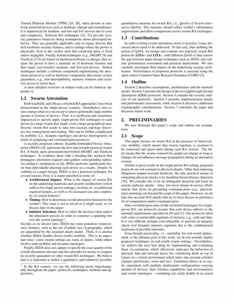
3.1.1 LISAα Protocol DetailsLISAα’s pseudo-code and finite state machine (FSM) for a prover
device (Dev) are illustrated in Algorithm 1 and an upper figure ofFigure 2, respectively. LISAα’s FSM for Vrf is illustrated in alower figure of Figure 2 and the pseudo-code is described in Algo-rithm 2. The protocol involves two message types:(1) request: Attreq = [“req”,Snd,Seq,Authreq ] and(2) report: Attrep = [“rep”,DevID,Par,Seq,H(Mem),Authrep]where:• Snd – identifier of the sending device; this field is not au-
thenticated• Seq – sequence number and/or timestamp of the present at-
testation instance; set by Vrf• Authreq – authentication token for the attestation request
message; computed by Vrf as: MAC(K, “req”||Seq)
Algorithm 1: Pseudo-code of LISAα for DevWrite-Protected Vars: DevID – id ofDev
CurSeq – current sequence #Par –Dev’s parent id
1 while True do2 m = RECEIVE();3 if TYPE(m) = “req” then4 [Snd,Authreq , Seq]← DECOMPOSE(m);5 if Seq < CurSeq then6 CONTINUE();7 end8 ifAuthreq 6= MAC(K, “req”||Seq) then9 CONTINUE();
10 end11 CurSeq ← Seq; Par ← Snd;12 BROADCAST(“req”||DevID||CurSeq||Authreq);13 Authrep ← MAC(K, “rep”||DevID||CurSeq||H(Mem));14 Attrep ←
“rep”||DevID||Par||CurSeq||H(Mem)||Authrep;15 UNICAST(Par,Attrep);16 else if TYPE(m) = “Rep” then17 Seq ← GETSEQ(m);18 if Seq = CurSeq then19 UNICAST(Par,m);20 end21 end22 end
• DevID – identifier ofDev; stored in ROM, along with AttCode• Par – identifier of the reporting device’s parent in the span-
ning tree; copied from Snd field in Attreq• Authrep – authentication token for the attestation reply mes-
sage; computed by Dev as:MAC(K, “rep”||DevID||Seq||H(Mem)), whereH() is asuitable cryptographic hash function andMem denotes de-vice memory that is subject to attestation3.
LISAα Prover.From the perspective of a prover Dev, LISAα has five states:
1. Wait: Dev waits for an attestation-relevant packet. In case ofAttreq , Dev proceeds to VerifyRequest and in case of Attrep, itjumps to VerifySession.2. VerifyRequest: Dev first checks validity of Seq, which must
be strictly greater than the previous stored value; otherwise, it dis-cards Attreq and returns to Wait. Next, Dev validates Authreq
by recomputing MAC. If verification fails, Dev discards Attreqand returns to Wait. Otherwise, Dev saves Seq as the current ses-sion number CurSeq, stores Snd as its parent device Par for thissession, and transitions to Attest.3. Attest: Dev sets Snd field inAttreq toDevID and broadcasts
the modifiedAttreq . Next,Dev computesAuthrep and composesAttrep, as defined above. Note that Authrep authenticates Parby virtue of coveringAttreq . Finally,Dev unicastsAttrep to Parand transitions to Wait.4. VerifySession: Dev receives Attrep from one of its descen-
dants. If the Seq in Attrep does not match its stored counterpartCurSeq, Dev discards Attrep and returns to Wait. Otherwise, itproceeds to Forward.5. Forward: Dev unicasts Attrep received in VerifySession, to
its stored Par and returns to Wait.
3Note that H(Mem) is part of Attrep. We can omit it to savespace, and have Vrf keep a mapping of (DevID,H(Mem)).However, this would take away Vrf’s ability to make decisionsbased on actual device signatures.
Waitstart
VerifyRequest
VerifySession
Attest
Forward
“req"
“rep"
¬OK
OK
¬OK
OK
Waitstart Initiate
CollectTally “rep"complete or
tAttest exp
Figure 2: LISAα FSM-s for Dev (top) and Vrf (bottom)
LISAα Verifier.From Vrf’s perspective, LISAα is simpler, with four states:
1. Wait: Vrf waits for external signal (e.g., from a user) to start anew attestation session. When it arrives, Vrf moves to Initiate.2. Initiate: Vrf sets the overall timeout and selects the initiator(s),
as discussed earlier. It then initializesAttest = Fail = ∅,Norep ={all DevID}. Next, Vrf sets Snd =Vrf, composes Attreq , sendsit (via unicast) to the initiator(s), and moves to Collect.3. Collect: Vrf waits for Attrep messages from the initiator(s) or
an overall timeout. If a timeout occurs, Vrf transitions to Tally.Upon receipt of Attrep, Vrf extracts and validates Authrep byrecomputing MAC. (Note that duplicate Attrep messages are as-sumed to be automatically detected and suppressed). There arethree possible outcomes:
i. Validation fails: Attrep is discarded,ii. Authrep is authentic and H(Mem) corresponds to an ex-
pected (legal) state of DevID’s attested memory: Vrf addsDevID to Attest, and removes it from Norep,
iii. Authrep is authentic and H(Mem) does not match any ex-pected state ofDevID’s attested memory: Vrf addsDevIDto Fail and removes it from Norep
If |Attest|+ |Fail| = n, Vrf moves to Tally; otherwise it remainsin Collect.4. Tally: Vrf outputs Attest, Fail and Norep as sets of devices
that passed, failed and didn’t reply, respectively. Finally, Vrf re-turns to Wait.

Algorithm 2: Pseudo-code of LISAα for Vrf1 tAttest ← ta + tMAC + 2 · n · tt + ts;2 while True do3 wait();4 InitID ← GETINITID();5 CurSeq ← GETSEQ();6 Attreq ← “req”||Vrf||CurSeq||Authreq ;7 UNICAST(InitID,Attreq);8 Attest← ∅; Fail← ∅;9 Norep← {allDevID};
10 T ← GETTIMER();11 while T < tAttest do12 Attrep ← RECEIVE();13 [DevID, Par, Seq,H(Mem),Authrep]
← DECOMPOSE(Attrep);14 if Seq = CurSeq ∧ Authrep =
MAC(K, “rep”||DevID||CurSeq||H(Mem)) then15 ifH(Mem) ⊂ EXPECTEDHASH(DevID) then16 Attest← Attest ∪ {DevID};17 else18 Fail← Fail ∪ {DevID};19 end20 Norep← Norep \ {DevID};21 end22 if |Attest|+ |Fail| = n then23 BREAK();24 end25 end26 OUTPUT(Attest, Fail, Norep);27 end
3.1.2 Vrf Timeout in LISAαAs follows from the protocol description (or, equivalently, from
FSMs and pseudocode), devices do not require a timeout. For itspart, Vrf sets the overall attestation timeout totAttest = ta + n · tMAC + 2 · n · tt + ts, where:• ta – time for Dev to perform self-attestation4
• tMAC – time for Dev to compute a MAC (to verify or gen-erate) over a short message• tt – time for Dev to transmit a message to another device• ts – slack time, which accounts for variabilities, i.e., possible
deviationstAttest represents the time corresponding to running LISAα over an-device swarm with the worst-case topology scenario, i.e., a real-istic upper bound. The worst-case is a line topology where Attreqprocessing is done in sequence, taking n·tMAC . Only one ta needsto be included in tAttest since the last device (the only leaf in thetree) finishes its attestation after all others. Also, since there are atmost n hops between Vrf and the last device, it takes n · tt to trans-mit Attreq to that device and the same amount of time to transmitthe last Attrep to Vrf.
3.1.3 Connectivity in LISAαLet t0 denote the time when Dev receives Authreq from Par,
trep,i denote the time when Par receives the ith Authrep fromDev and z denote the number of Dev’s descendants. The connec-tivity assumption of LISAα can be formally stated as follows:
LISAα produces a correct swarm attestation result, i.e. no falsepositives and no false negatives, if a link between every Dev andits Par exists during their t0, trep,1, trep,2,...,trep,z+1.
3.1.4 QoSA of LISAαAt the end, Vrf collects a set ofAttrep messages, one from each
device. After verifying all Attrep-s, Vrf learns the list of success-
4In case of heterogeneous devices, ta represents the maximum self-attestation time across all devices. The same applies to tMAC andtt.
fully attested devices, thus achieving L-QoSA. It is easy to augmentthe protocol to collect topology information along with attestationresults. This can be performed by simply including Par in eachAttrep. Vrf then can thus reconstruct the topology based on veri-fied reports. Specifically, line 15 in Algorithm 1 would become:Authrep ← MAC(K, “rep”||CurSeq||DevID||Par||H(Mem));However, topology information obtained by Vrf is not reliable,since Par is not authenticated upon receiving Attreq . Fixing thisis not hard; it would require each device to: (1) compute and attachan extra MAC, at least over Par and Authreq fields, at Attreqforwarding time, and (2) verify the Par’s MAC upon receivingAttreq .
3.1.5 Complexity of LISAαComplexity is discussed in Appendix B.1. In brief, LISAα is
very simple in terms of software complexity and impose no addi-tional features on the underlying attestation architecture. However,it requires a larger ROM and additional static MPU rules. Also,high communication overhead is LISAα’s biggest drawback, sinceDev transmits n reports in the worst case. This motivates the de-sign of LISAs, which aims to reduce communication overhead byaggregating multiple Attrep-s.
3.2 Synchronous Version: LISAsThe main idea in LISAs is to let devices authenticate and attest
each other. When one device is attested by another, only the iden-tifier of the former needs to be securely forwarded to Vrf, insteadof the entire Attrep. This translates into considerable bandwidthsavings and lower Vrf workload. Also, Attrep-s can be aggre-gated, which decreases the number of packets sent and received.It also allows more flexibility in terms of QoSA: from B-QoSA toF-QoSA. Finally, malformed or fake Attrep-s are detected in thenetwork and not propagated to Vrf, as in LISAα. However, thesebenefits are traded off for increased protocol (and code) complex-ity, as described below.
LISAs’s main distinctive feature is that each Dev waits for allof its children’Attrep-s before submitting its own. This makes theprotocol synchronous. EachDev keeps track of its parent and chil-dren during an attestation session. Once Attreq is processed andpropagated, Dev waits for each child to complete attestation bysubmitting a Attrep. Then, Dev verifies each Attrep, aggregatesa list of children as well as descendants they attested, attests itself,and finally sends its authenticated Attrep (which contains the listof attested descendants) to its Par.
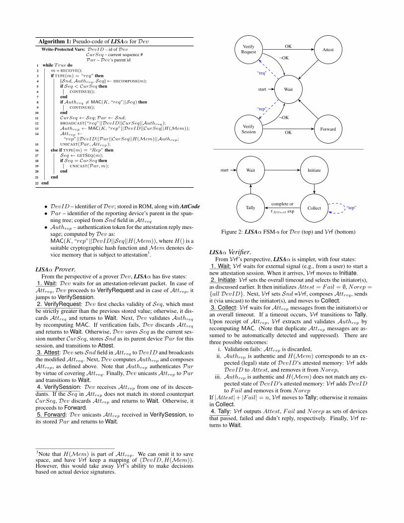
3.2.1 LISAs Protocol DetailsThe FSM and pseudo-code for Dev are shown in an upper part
of Figure 3 and Algorithm 3, respectively. Design choices are dis-cussed in Appendix C. LISAs is constructed such that Dev canreceive a newAttreq in any state, even while waiting for children’sAttrep-s. Besides Attreq and Attrep, LISAs involves one extramessage type:(1) request: Attreq = [“req”,Snd,Seq,Depth,Authreq],(2) report: Attrep = [“rep”,Seq,DevID,Desc,Authrep], and(3) acknowledgment: Attack = [“ack”,Seq,DevID,Par], with:• Snd– identifier of the sending device; this field is not au-
thenticated• Seq– sequence number and/or timestamp of the present at-
testation instance; set by Vrf• Depth– depth of the sending device in the spanning tree• Authreq– authentication token for the attestation request mes-
sage; computed by Vrf as: MAC(K, “req”||Seq)• DevID– identifier of Dev (in ROM, along with AttCode)
Wait
start
Answer+ Broadcast
+ Reset
AcceptChild
VerifyRequest
VerifyTimer + Ack
VerifySession
Attest+
Answer
AggregateReport
“req"
“rep"
“ack"
tREP exp
¬OK
OK
¬OK
OK
¬OK
OK
incomplete
complete
Waitstart Initiate
AcceptChild
CollectTally
“ack"
tACK exp
“rep"complete or
tREP exp
Figure 3: FSM of LISAs: Dev (top) and Vrf (bottom)
• Desc– list of Dev’s descendants; populated when Dev re-ceives an authentic report• Authrep– authentication token for the attestation reply mes-
sage; computed by Dev as:MAC(K, “rep”||Seq||DevID||Desc)• Par– identifier of reporting device’s parent in the spanning
tree; copied from Snd field in Attreq
Prover in LISAs .From the perspective of a prover Dev, LISAs consists of eight
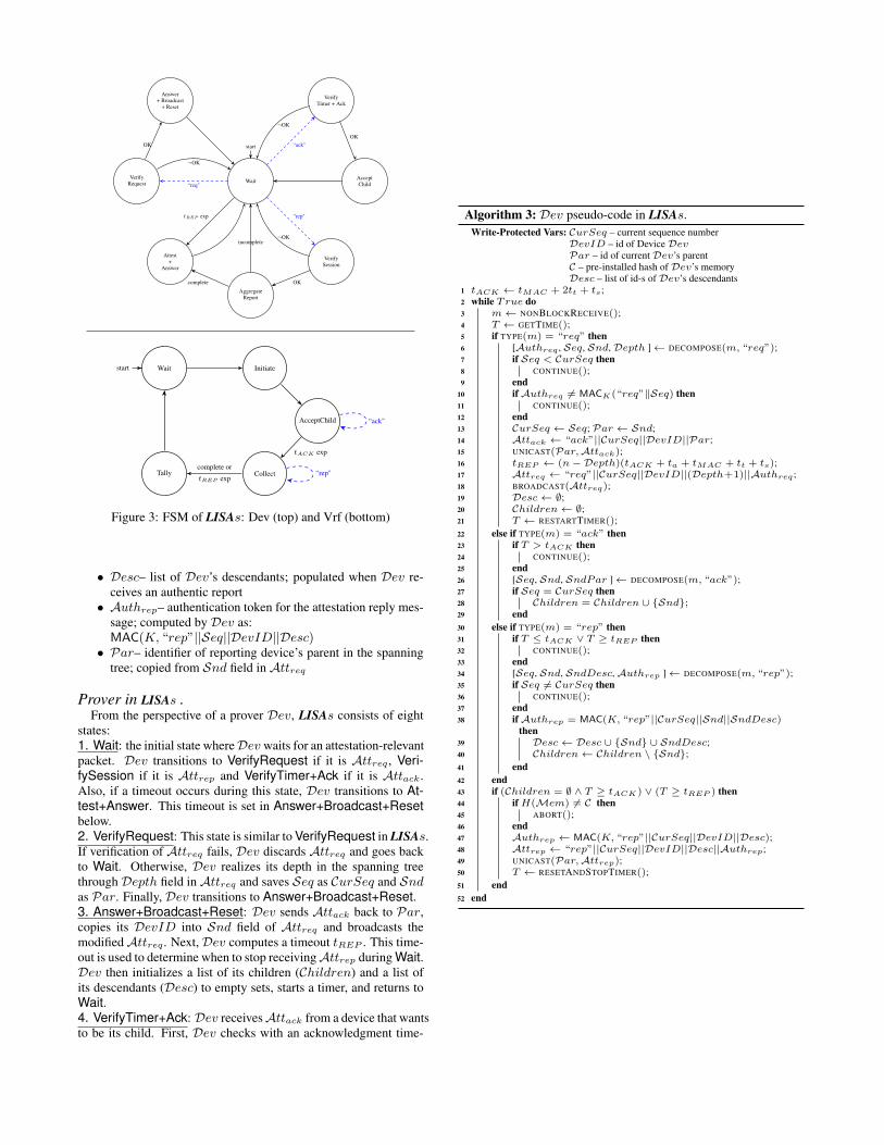
states:1. Wait: the initial state whereDev waits for an attestation-relevantpacket. Dev transitions to VerifyRequest if it is Attreq , Veri-fySession if it is Attrep and VerifyTimer+Ack if it is Attack.Also, if a timeout occurs during this state, Dev transitions to At-test+Answer. This timeout is set in Answer+Broadcast+Resetbelow.2. VerifyRequest: This state is similar to VerifyRequest in LISAs.If verification of Attreq fails, Dev discards Attreq and goes backto Wait. Otherwise, Dev realizes its depth in the spanning treethrough Depth field inAttreq and saves Seq as CurSeq and Sndas Par. Finally, Dev transitions to Answer+Broadcast+Reset.3. Answer+Broadcast+Reset: Dev sends Attack back to Par,copies its DevID into Snd field of Attreq and broadcasts themodifiedAttreq . Next,Dev computes a timeout tREP . This time-out is used to determine when to stop receivingAttrep during Wait.Dev then initializes a list of its children (Children) and a list ofits descendants (Desc) to empty sets, starts a timer, and returns toWait.4. VerifyTimer+Ack: Dev receivesAttack from a device that wantsto be its child. First, Dev checks with an acknowledgment time-
Algorithm 3: Dev pseudo-code in LISAs.Write-Protected Vars: CurSeq – current sequence number
DevID – id of DeviceDevPar – id of currentDev’s parentC – pre-installed hash ofDev’s memoryDesc – list of id-s ofDev’s descendants
1 tACK ← tMAC + 2tt + ts;2 while True do3 m← NONBLOCKRECEIVE();4 T ← GETTIME();5 if TYPE(m) = “req” then6 [Authreq , Seq, Snd,Depth ]← DECOMPOSE(m, “req”);7 if Seq < CurSeq then8 CONTINUE();9 end
10 ifAuthreq 6= MACK(“req”‖Seq) then11 CONTINUE();12 end13 CurSeq ← Seq; Par ← Snd;14 Attack ← “ack”||CurSeq||DevID||Par;15 UNICAST(Par,Attack);16 tREP ← (n−Depth)(tACK + ta + tMAC + tt + ts);17 Attreq ← “req”||CurSeq||DevID||(Depth+1)||Authreq ;18 BROADCAST(Attreq);19 Desc← ∅;20 Children← ∅;21 T ← RESTARTTIMER();22 else if TYPE(m) = “ack” then23 if T > tACK then24 CONTINUE();25 end26 [Seq, Snd, SndPar ]← DECOMPOSE(m, “ack”);27 if Seq = CurSeq then28 Children = Children ∪ {Snd};29 end30 else if TYPE(m) = “rep” then31 if T ≤ tACK ∨ T ≥ tREP then32 CONTINUE();33 end34 [Seq, Snd, SndDesc,Authrep ]← DECOMPOSE(m, “rep”);35 if Seq 6= CurSeq then36 CONTINUE();37 end38 ifAuthrep = MAC(K, “rep”||CurSeq||Snd||SndDesc)
then39 Desc← Desc ∪ {Snd} ∪ SndDesc;40 Children← Children \ {Snd};41 end42 end43 if (Children = ∅ ∧ T ≥ tACK) ∨ (T ≥ tREP ) then44 ifH(Mem) 6= C then45 ABORT();46 end47 Authrep ← MAC(K, “rep”||CurSeq||DevID||Desc);48 Attrep ← “rep”||CurSeq||DevID||Desc||Authrep;49 UNICAST(Par,Attrep);50 T ← RESETANDSTOPTIMER();51 end52 end

out (tACK ), which is a global constant. If the current time is laterthan tACK , Dev discards Attack and returns to Wait. If the Seqin Attack does not match CurSeq, Dev also discards Attack andgoes back to Wait. Otherwise, Dev transitions to AcceptChild.5. AcceptChild: Dev acceptsAttack and stores Snd into Children.Then, Dev returns to Wait.6. VerifySession: This state is also similar to VerifySession inLISAα. Dev discards Attrep and return to Wait if Seq in Attrepdoes not match CurSeq. Otherwise, it transitions to AggregateRe-port7. AggregateReport: Dev accepts Attrep and aggregates it withother received reports in the same session. The aggregation is doneby adding Snd and Desc fields in Attrep into its Desc and re-moving Snd from Children since Snd has replied. If all of itschildren have already replied (or Children = ∅), Dev transitionsto Attest+Answer. Otherwise, Dev returns to Wait.8. Attest+Answer: Dev computes a hash of its attestable mem-ory. If the resulting digest does not match with the pre-installedhash value (C), Dev outputs an error and acts accordingly (e.g.,hardware reset and memory wipe-out). Otherwise, Dev constructsAuthrep andAttrep as defined earlier and unicastsAttrep toPar.Finally, the timer is reset and stopped and Dev returns to Wait.
Verifier in LISAs .The Vrf in LISAs has one additional state – AcceptChild –
while the rest of the states remain similar or the same as the ones inLISAα. Vrf’s pseudo-code is illustrated below and its finite statemachine is in the lower part of Figure 3.1&2. Wait and Initiate: These two state are identical to their coun-terparts in LISAα.3. AcceptChild: Vrf waits forAttack-s from the initiator(s), whichare used to determine the completion of Collect. After a timeoutoccurs, Vrf stops receiving Attack-s and transitions to Collect.4. Collect: This state is also similar to Collect in LISAα exceptthe following three behaviors: One is Vrf does not need to checkH(Mem) since it is not include in Attrep. Secondly, Vrf doesnot need to maintain a list of unsuccessfully attested devices (Fail)since software-infected devices cannot output an authenticAuthrep.Lastly, Vrf transitions to Tally if the initiator(s) (realized in Ac-ceptChild) has sent its reports. The rest of its behaviors remainsthe same as in LISAα.5. Tally: Vrf outputs Attest and Norep and returns to Wait.
3.2.2 Timeouts in LISAsDev requires two timeouts: an acknowledgment timeout (tACK )
and a report timeout (tREP ).tACK is the amount of time that Dev waits after having broad-
cast a request for children acknowledgments. It is set to the con-stant value of tMAC+2tt+ts, that is time for the broadcast to reacha neighbor (tt), for the neighbor to verify the request (tMAC ), andthen for the answer to be received by Dev (another tt), plus someslack ts (global parameter). This gives all neighbors an opportunityto send Attack.tREP is the amount of time, after the children have been deter-
mined, that Dev will wait for reports before performing its own at-testation. It is set to the value (n−Depth)(tACK + ta + tMAC +tt + ts). This represents the time the descendants would take toanswer back to Dev in the absolute worst scenario. This scenariois when the descendants are in a line topology and each has onlyone child (except the last one). It is indeed the worst case becauseno work can be done in parallel. Each node in the line (except theleaf) will perform the following: forward a request to and wait forthe answer from its (only) child (tACK ), and then, after receiving
Algorithm 4: Vrf pseudo-code in LISAs.1 tACK ← tMAC + 2tt + ts;2 tAttest ← n · (tACK + ta + tMAC + tt + ts);3 while True do4 wait();5 InitID ← GETINITID();6 CurSeq ← GETSEQ();7 Attreq ← “req”||Vrf||CurSeq||Authreq ;8 UNICAST(InitID,Attreq);9 Attest← ∅; Children← ∅;
10 Norep← {allDevID};11 T ← GETTIMER();12 while T < tACK do13 Attack ← RECEIVE();14 [Seq,DevID, Par]← DECOMPOSE(Attack);15 if Seq = CurSeq then16 Children← Children ∪ {DevID};17 end18 end19 while T < tREP do20 Attrep ← RECEIVE();21 [Snd, Par, Seq, SndDesc,Authrep]
← DECOMPOSE(Attrep);22 if Seq = CurSeq ∧ Authrep =
MAC(K, “rep”||Seq||DevID||SndDesc) then23 Attest← (Attest ∪ SndDesc) ∪ {Snd};24 Norep← (Norep \ SndDesc) \ {Snd};25 Children← Children \ {Snd};26 end27 if Children = ∅ ∨ |Attest| = n then28 BREAK();29 end30 end31 OUTPUT(Attest,Norep);32 end
the answer, verify its child’s report (tMAC ), attest itself (ta), andfinally answer back to the parent (tt) and some slack ts for variabil-ity considerations. In this scenario, all of Dev’s descendants willtake this time (except the leaf which takes slightly less). IfDev hasDepth ancestors, it has at most (n−Depth) descendants. Hence,time for attestation of descendants is bounded, even in the worst-case scenario, by: (n − Depth)(tACK + ta + tMAC + tt + ts).Note that the timeouts are needed to detect errors and DoS attacks.In most topologies, the delay in gathering reports will be muchshorter. Finally, Depth is important: without it, if a node timesout, its parent (and all ancestors) will also time out. Then, Vrfwould have no idea about what happened. Instead, if a node timesout, it sends what it has thus far to its parent, which does not timeout itself.
Since Vrf can be viewed as the root of the spanning tree, tACK
and tREP are applicable to it. Vrf’s tREP = n · (tACK + ta +tMAC + tt + ts).
3.2.3 Connectivity in LISAsLet t0 denote the time that Dev receives Authreq from Par,
t1 denote the time that Par receives Attack from Dev and t2 de-note the time that Par receives Authrep from Dev. Then, we canformally state the connectivity assumption in LISAs as follows:
LISAs provides correct swarm attestation result, i.e. no false-positive and false-negative, if a link between every Dev and itsPar exists during their t0, t1 and t2.
Note that this assumption is more relaxed than the one in LISAαsince each link has to appear during those three times while inLISAα, Dev and Par have to be connected for transmitting z + 1messages where z is a number of Dev’s descendants. The down-side, however, is that when the assumption does not hold, Vrf willlose all Authrep-s of Dev and its descendants while in LISAα,some of those Authrep-s could still arrive to Vrf.
3.2.4 QoSA of LISAsAs presented in Algorithm 3, LISAs offers L-QoSA. By chang-
ing information contained in the reports (line 48), QoSA can beamended to:• Binary: Instead of Desc, Attrep contains a single bit in-
dicating whether all descendants have been successfully at-tested. This saves bandwidth over L-QoSA since reports aresmaller (the MAC is also faster to compute). The obviousdownside is that Vrf is only learns the result of swarm attes-tation as a whole, and can not identify missing devices. Oneoption is to use LISAs with B-QoSA until failure is encoun-tered and then re-run LISAs with higher QoSA to identifydevices that failed attestation.• Counter: Using a counter allows Vrf to learn how many de-
vices failed attestation. This comes at a marginal increase isbandwidth consumption.• List Complement: Instead of composing a list of attested de-
scendants, each device can build a list of unattested ones. In amostly healthy swarm, this is cheaper in terms of bandwidththan list QoSA.• Topology: By representing the list of descendants as a tree in-
stead of a set in the report, LISAs can provide topology infor-mation to Vrf. Specifically, line 39 is replaced by: Desc ←Desc∪(Snd : SndDesc). This recursively creates a subtreerooted at each node. The only drawback is a small increasein bandwidth usage.
4. SECURITY ANALYSISWe now describe possible attacks and then (informally) assess
security of LISAα and LISAs.
4.1 Attack VectorsRecall that our adversarial model only considers remote and lo-
cal adversaries, while physical attacks are out of scope. An ad-versary Adv can remotely modify the software and/or the state ofany device. It also has full control of all communication channels,i.e., can eavesdrop on, inject, delete, delay or modify any messagesbetween devices, as well as between any device and Vrf. In thecontext of LISA, the following attacks are possible:
1. Report Forgery: Forging a Attrep would allow a device toevade detection of malware, or allow Adv to impersonate adevice.
2. Request Forgery: Forging a Attreq would trigger unneces-sary swarm attestation and result in denial-of-service (DoS)for the entire swarm.
3. Application Layer DoS: Adv can launch a DoS attack abus-ing the attestation protocol itself. This type of attack canvary, depending on the protocol version. One example isflooding the swarm with fake Attrep-s.
4. DoS on Network Layer and Lower Layers: Adv can launcha DoS attacks that target network, link and physical layers ofdevices. This includes radio jamming, random packet flood-ing, packet dropping, etc. We do not consider such attackssince they are not specific to swarm attestation.
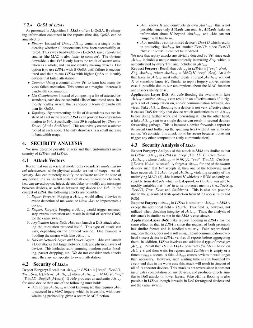
4.2 Security of LISAαReport Forgery: Recall thatAttrep in LISAα is [“rep”,DevID,Par,Seq,H(Mem),Authrep] whereAuthrep = MAC(K, “rep”||DevID||Seq||H(Mem)). IfAdv produces an authenticAttrepfor some device then one of the following must hold:• Adv forgesAuthrep without knowingK: this requiresAdv
to succeed in a MAC forgery, which is infeasible, with over-whelming probability, given a secure MAC function.
• Adv knows K and constructs its own Authrep: this is notpossible, since only AttCode can read K, AttCode leaks noinformation about K beyond Authrep, and Adv can nottamper with hardware.• Adv modifies a compromised device’sDevID which results
in producing Authrep for another DevID: since DevID“lives” in ROM, it can not be modified.
We note that replay attacks are trivially detected by Vrf since eachAttreq includes a unique monotonically increasing Seq, which isauthenticated by every Dev and included in Attrep.Request Forgery: Recall that Attreq in LISAα is [“req”,Snd,Seq,Authreq] whereAuthreq = MAC(K, “req”||Seq). AnAdvthat fakes an Attreq must either create a forged Authreq withoutK or somehow know K. Similar to report forgery above, neithercase is possible due to our assumptions about the MAC functionand inaccessibility of K.Application Layer DoS: An Adv flooding the swarm with fakeAttrep-s and/or Attreq-s can result in an effective attack if it trig-gers a lot of computation on, and/or communication between, de-vices. Fake Attreq flooding to a device is not very effective sinceit causes DoS for only that device which authenticates an Attreqbefore doing further work and forwarding it. On the other hand,a fake Attrep sent to a single device can result in several devicesforwarding garbage. This is because a device forwards a report toits parent (and further up the spanning tree) without any authenti-cation. We consider this attack not to be severe because it does nottrigger any other computation (only communication).
4.3 Security Analysis of LISAsReport Forgery: Analysis of this attack in LISAs is similar to thatin LISAα. Attrep in LISAs is [“rep”,DevID, CurSeq,Desc,Authrep], where Authrep = MAC(K, “rep”||DevID||CurSeq||Desc). IfAdv successfully forges aAttrep for one of the swarmdevices such that Vrf accepts it, then one of the following musthave occurred: (1) Adv forged Authrep violating security of theunderlying MAC; (2)Adv learnedK which is in ROM and only ac-cessible from AttCode which is leak-proof; or (3) Adv was able tomodify variables that “live" in write-protected memory (i.e., CurSeq,DevID, Par, Desc and Children). This is also not possibledue to the guaranteed write-protection from MPU access rules andROM.Request Forgery: Attreq in LISAs is similar toAttreq in LISAαexcept the additional field – Depth. This field is, however, notutilized when checking integrity of Attreq . Thus, the analysis ofthis attack is similar to that in the LISAα case above.Application-Layer DoS: Fake request flooding in LISAs has thesame effect as that in LISAα since the request of both protocolshas similar format and is handled similarly. Fake report flood-ing, nonetheless, does not result in significant communication over-head since a device in LISAs verifies all reports before aggregatingthem. In addition, LISAs involves one additional type of message:Attack. Recall that Dev in LISAs constructs Children based onAttack-s and then waits for reports until Children is empty or atimeout tREP occurs. A fakeAttack causes devices to wait longerthan necessary. However, such waiting time is still bounded bytREP and thus in the worst case this attack will result in timeout ofall of its ancestor devices. This attack is not severe since it does notincur extra computation on any devices, and produces effects sim-ilar to DoS attacks on lower layers. Fake Attack flooding is alsopossible in LISAs, though it results in DoS for targeted devices andnot the entire swarm.
5. EXPERIMENTAL ASSESSMENTWe implemented LISAα and LISAs in Python, and assessed
their performance by emulating device swarms using the open-source Common Open Research Emulator (CORE) [2].
5.1 Experimental Setup and ParametersCORE Emulator: CORE is a framework for emulating networks.It allows defining network topologies with lightweight virtual ma-chines (VMs). CORE contains Python modules for scripting net-work emulations at different layers of the TCP/IP stack and al-lows defining mobility scenario for nodes, configuring routing andswitching, network traffic and applications running inside emulatedVMs. One key advantage of CORE over other simulation frame-works, such as ns2 or ns3, is that it utilizes the actual network stackin Linux and instantiates each emulated node using a lightweightVM with its own file system running its own processes. Using theactual networking stack results in performance estimates very closeto reality, since it does not abstract away any implementation de-tails or issues at the data link, network and transport layers.Experimental Setup & Scenarios: We generated several COREscenarios with n nodes each. In every scenario, the positions of then nodes are chosen uniformly at random in an area of 1, 500× 800units, e.g., meters. A pair of nodes is connected if the distance be-tween them is smaller then a threshold of 200 units, correspond-ing roughly to the coverage range of 802.11/WiFi. If the result-ing network is not connected, the above process is repeated until aconnected network is generated. Vrf is also randomly positionedwithin the area, and connected to the generated network. Figure 6in Appendix E in shows a sample configuration.
The link-layer medium access control protocol running betweenneighboring nodes is 802.11. Network layer (IP) routing tablesare automatically populated via the Optimized Link State Rout-ing (OLSR) protocol, an IP-based routing protocol optimized forMANETs. OLSR uses proactive link-state routing with “Hello"and “Topology Control" messages that discover and disseminatelink state information throughout the network. Each node usestopology information to compute next-hop destinations for all othernodes using the shortest path algorithm. Each node then runs ourswarm attestation protocol, though instead of actually performingcryptographic operations, we insert delays (specified below) corre-sponding to time to perform such operations on low-end devices.At the beginning of each experiment, Vrf broadcasts a new Attreqthat is propagated throughout the network according to LISAα orLISAs.Timings of Cryptographic Operations: Delays used to mimiccryptographic operations on low-end devices are as follows:• Vrf signature computation/verification: 0.0001s• Node signature computation/verification: 0.001s• Node hash speed (for attestation): 0.0429s/MB
The scheme used to sign messages can be implemented by a MACor a public key signature scheme such as ECDSA (see Section 6).These timings are based on using ECDSA-160 and SHA-256. Us-ing a MAC would reduce the time for small memory sizes. How-ever, as discussed in Sections 5.2 and 6, computation is generallydominated by hashing. Numbers for Vrf are derived from a typicallaptop, and those for Dev nodes come from a Raspberry Pi-2.
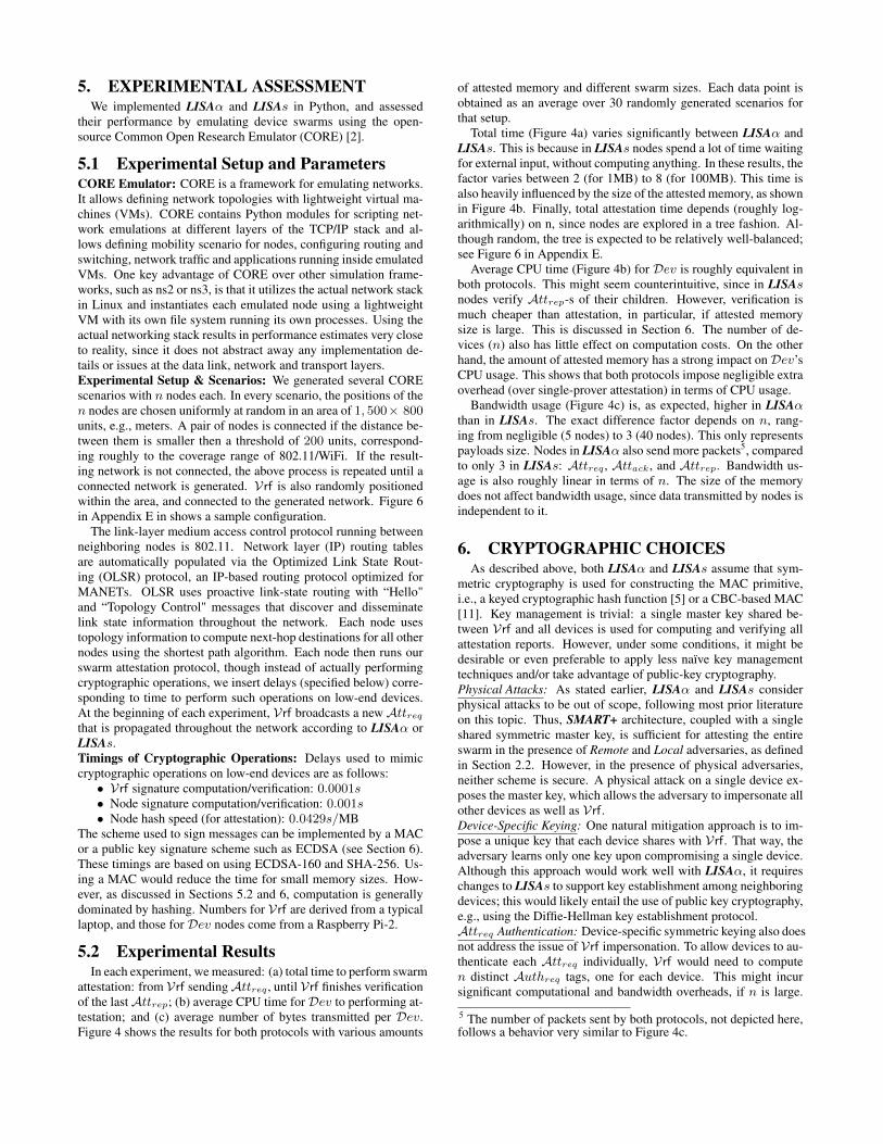
5.2 Experimental ResultsIn each experiment, we measured: (a) total time to perform swarm
attestation: from Vrf sendingAttreq , until Vrf finishes verificationof the lastAttrep; (b) average CPU time forDev to performing at-testation; and (c) average number of bytes transmitted per Dev.Figure 4 shows the results for both protocols with various amounts
of attested memory and different swarm sizes. Each data point isobtained as an average over 30 randomly generated scenarios forthat setup.
Total time (Figure 4a) varies significantly between LISAα andLISAs. This is because in LISAs nodes spend a lot of time waitingfor external input, without computing anything. In these results, thefactor varies between 2 (for 1MB) to 8 (for 100MB). This time isalso heavily influenced by the size of the attested memory, as shownin Figure 4b. Finally, total attestation time depends (roughly log-arithmically) on n, since nodes are explored in a tree fashion. Al-though random, the tree is expected to be relatively well-balanced;see Figure 6 in Appendix E.
Average CPU time (Figure 4b) for Dev is roughly equivalent inboth protocols. This might seem counterintuitive, since in LISAsnodes verify Attrep-s of their children. However, verification ismuch cheaper than attestation, in particular, if attested memorysize is large. This is discussed in Section 6. The number of de-vices (n) also has little effect on computation costs. On the otherhand, the amount of attested memory has a strong impact onDev’sCPU usage. This shows that both protocols impose negligible extraoverhead (over single-prover attestation) in terms of CPU usage.
Bandwidth usage (Figure 4c) is, as expected, higher in LISAαthan in LISAs. The exact difference factor depends on n, rang-ing from negligible (5 nodes) to 3 (40 nodes). This only representspayloads size. Nodes in LISAα also send more packets5, comparedto only 3 in LISAs: Attreq , Attack, and Attrep. Bandwidth us-age is also roughly linear in terms of n. The size of the memorydoes not affect bandwidth usage, since data transmitted by nodes isindependent to it.
6. CRYPTOGRAPHIC CHOICESAs described above, both LISAα and LISAs assume that sym-
metric cryptography is used for constructing the MAC primitive,i.e., a keyed cryptographic hash function [5] or a CBC-based MAC[11]. Key management is trivial: a single master key shared be-tween Vrf and all devices is used for computing and verifying allattestation reports. However, under some conditions, it might bedesirable or even preferable to apply less naïve key managementtechniques and/or take advantage of public-key cryptography.Physical Attacks: As stated earlier, LISAα and LISAs considerphysical attacks to be out of scope, following most prior literatureon this topic. Thus, SMART+ architecture, coupled with a singleshared symmetric master key, is sufficient for attesting the entireswarm in the presence of Remote and Local adversaries, as definedin Section 2.2. However, in the presence of physical adversaries,neither scheme is secure. A physical attack on a single device ex-poses the master key, which allows the adversary to impersonate allother devices as well as Vrf.Device-Specific Keying: One natural mitigation approach is to im-pose a unique key that each device shares with Vrf. That way, theadversary learns only one key upon compromising a single device.Although this approach would work well with LISAα, it requireschanges to LISAs to support key establishment among neighboringdevices; this would likely entail the use of public key cryptography,e.g., using the Diffie-Hellman key establishment protocol.Attreq Authentication: Device-specific symmetric keying also doesnot address the issue of Vrf impersonation. To allow devices to au-thenticate each Attreq individually, Vrf would need to computen distinct Authreq tags, one for each device. This might incursignificant computational and bandwidth overheads, if n is large.
5 The number of packets sent by both protocols, not depicted here,follows a behavior very similar to Figure 4c.

(a) Total time [s] for swarm attestation in LISAα and LISAs, for differentmemory sizes, as a function of n (log y-scale).
(b) Average CPU time [s] per device for LISAα and LISAs, for differentmemory sizes, as a function of n (log y-scale).
(c) Average # bytes transmitted per device for LISAα and LISAs, for dif-ferent memory sizes, as a function of n (linear y-scale).
Figure 4: Experimental Results for LISAα and LISAs
For small swarms, the tradeoff could be acceptable. Regardless ofwhether a single master key or device-specific keys are used, onesimple step towards preventing Vrf impersonation and consequentDoS attacks is to impose a public key on Vrf only. In other words,Vrf would sign each Attreq , thus changing the format of Authreq
to: SIGN(SKVrf , “req”||Seq) where SKVrf is Vrf’s private keyand PKVrf is its public counterpart, assumed to be known to alldevices. One obvious downside of this simple method is the extracomputational overhead of verifying Authreq . We note that thecombination of: (1) public key-based Attreq authentication, and(2) per device symmetric keys, is both appropriate and efficient forLISAα, which does not require devices to authenticate each other’sAttrep-s. It makes less sense for LISAs, due to the need for ameans to authenticate one’s neighbors’ Attrep-s.Public Keys for All: Predictably, we now consider imposing a uniquepublic/private key-pair for each device. Admittedly, this only mit-igates the effects of physical attacks and clearly does not preventthem. However, a successful physical attack on a single deviceyields knowledge of that device’s secret key and does not lead toimpersonation, or easier compromise, of other devices. For LISAα,there is almost no difference between the full-blown public key ap-proach and device-specific symmetric keying, as long as either iscoupled with public key-based Attreq authentication. The onlyissue arises if Vrf is not fully trusted; in that case, the former ispreferable since Vrf would not be able to create fake Attrep-s. ForLISAs, using device-specific public keys is conceptually simpler asthere would be no need to establish pairwise keys between neigh-bors.Attested Memory Size: An orthogonal (non-security) issue influ-encing cryptographic choices is the size of attested memory. Con-sidering relatively weak low-end embedded devices, the cost ofcomputing a symmetric MAC (dominated by computing a hash)over a large segment of memory might exceed that of computing asingle public key signature. In that case, it makes sense to employ adigital signature in both LISAα and LISAs. To illustrate this point,Figure 5 compares performance of SHA-256 with several signaturealgorithms on Raspberry Pi-2. When attested memory size reaches45KB, the run-time of Elliptic Curve Digital Signature Algorithm(ECDSA) with a 256-bit public key catches up to that of SHA-256.Hence, at least with Raspberry Pi-2, it makes sense to switch toECDSA-256 for memory sizes exceeding 4.5MB – at that point,ECDSA-256 consumes less than 1% of total attestation runtime.
Figure 5: Performance Comparison: Hash & Signature on Rasp-berry Pi-2@900MHz [17].

7. CONCLUSIONS & FUTURE WORKThis paper brings swarm RA closer to reality by designing two
simple and practical protocols: LISAα and LISAs. To analyze andcompare across protocols we introduced a new metric: Quality ofSwarm Attestation (QoSA) which captures the information offeredby a specific swarm RA protocol. Issues for future work include:(i) formally proving security for swarm protocols, and (ii) trial de-ployment of proposed protocols on device swarms.
AcknowledgmentsThe authors are grateful to AsiaCCS’17 anonymous reviewers forhelpful comments and improvement suggestions. UCI authors weresupported, in part, by funding from: (1) the National Security Agency(NSA) under contract H98230-15-1-0276, (2) the Department ofHomeland Security, under subcontract from the HRL Laboratories,(3) the Army Research Office (ARO) under contract W911NF-16-1-0536, and (4) a fellowship of the Belgian American EducationalFoundation.
8. REFERENCES[1] T. Abera, N. Asokan, L. Davi, F. Koushanfar, A. Paverd,
A.-R. Sadeghi, and G. Tsudik. Invited: Things, trouble, trust:on building trust in IoT systems. In ACM/IEEE DesignAutomation Conference (DAC), 2016.
[2] J. Ahrenholz. Comparison of CORE network emulationplatforms. In IEEE Military Communications Conference(MILCOM), 2010.
[3] Apple Computer, Inc. LibOrange, 2006.[4] N. Asokan, F. Brasser, A. Ibrahim, A.-R. Sadeghi,
M. Schunter, G. Tsudik, and C. Wachsmann. SEDA: Scalableembedded device attestation. In ACM SIGSAC Conferenceon Computer and Communications Security (CCS), 2015.
[5] M. Bellare, R. Canetti, and H. Krawczyk. Keying hashfunctions for message authentication. In IACR Crypto, 1996.
[6] F. Brasser, B. El Mahjoub, A.-R. Sadeghi, C. Wachsmann,and P. Koeberl. TyTAN: tiny trust anchor for tiny devices. InACM/IEEE Design Automation Conference (DAC), 2015.
[7] F. Brasser, A.-R. Sadeghi, and G. Tsudik. Remote attestationfor low-end embedded devices: the prover’s perspective. InACM/IEEE Design Automation Conference (DAC), 2016.
[8] J. Camhi. BI Intelligence projects 34 billion devices will beconnected by 2020.
[9] K. Eldefrawy, G. Tsudik, A. Francillon, and D. Perito.SMART: Secure and minimal architecture for (establishingdynamic) root of trust. In Network and Distributed SystemSecurity Symposium (NDSS), 2012.
[10] A. Ibrahim, A.-R. Sadeghi, G. Tsudik, and S. Zeitouni.DARPA: Device attestation resilient to physical attacks. InACM Conference on Security and Privacy in Wireless andMobile Networks (WiSec), 2016.
[11] Information technology – Security techniques – MessageAuthentication Codes (MACs) – Part 1: Mechanisms using ablock cipher. Standard, ISO.
[12] A. Kandhalu, K. Lakshmanan, and R. R. Rajkumar.U-connect: a low-latency energy-efficient asynchronousneighbor discovery protocol. In ACM/IEEE Conference onInformation Processing in Sensor Networks (IPSN), 2010.
[13] P. Koeberl, S. Schulz, A.-R. Sadeghi, and V. Varadharajan.TrustLite: A security architecture for tiny embedded devices.In ACM European Conference on Computer Systems(EuroSys), 2014.
[14] M. Kohvakka, J. Suhonen, M. Kuorilehto, V. Kaseva,M. Hännikäinen, and T. D. Hämäläinen. Energy-efficientneighbor discovery protocol for mobile wireless sensornetworks. Ad Hoc Networks, 7(1):24–41, 2009.
[15] B. Parno. Bootstrapping trust in a Trusted Platform. In 3rdUSENIX Conference on Hot Topics in Security (HotSec),2008.
[16] D. Puri. Got milk? IoT and LoRaWAN modernize livestockmonitoring.
[17] RASPBERRY PI FOUNDATION. RASPBERRY PI 2MODEL B, 2015.
[18] A.-R. Sadeghi, M. Schunter, A. Ibrahim, M. Conti, andG. Neven. SANA: Secure and scalable aggregate networkattestation. In ACM Conference on Computer andCommunications Security (CCS), 2016.
[19] E. Sahin. Swarm robotics: From sources of inspiration todomains of application. In International workshop on swarmrobotics, pages 10–20. Springer, 2004.
[20] D. Schellekens, B. Wyseur, and B. Preneel. Remoteattestation on legacy operating systems with trusted platformmodules. Science of Computer Programming, 74(1):13 – 22,2008.
[21] A. Seshadri, M. Luk, A. Perrig, L. van Doorn, and P. Khosla.Scuba: Secure code update by attestation in sensor networks.In ACM Workshop on Wireless Security (WiSe), 2006.
[22] A. Seshadri, M. Luk, E. Shi, A. Perrig, L. van Doorn, andP. Khosla. Pioneer: Verifying code integrity and enforcinguntampered code execution on legacy systems. ACMSIGOPS Operating Systems Review, December 2005.
[23] A. Seshadri, A. Perrig, L. Van Doorn, and P. Khosla.SWATT: Software-based attestation for embedded devices.In IEEE Symposium on Research in Security and Privacy(S&P), 2004.
[24] F. Stumpf, O. Tafreschi, P. Röder, and C. Eckert. A robustintegrity reporting protocol for remote attestation. InWorkshop on Advances in Trusted Computing (WATC), 2006.
[25] Trusted Computing Group. Trusted platform module (tpm).[26] R. Waugh. Smart TV hackers are filming people having sex
on their sofas.

APPENDIXA. RELATED WORK
Initial RA efforts relied on secure hardware exemplified by theTrusted Platform Module (TPM) [25]. (A TPM is a secure co-processor, designed for protecting a secret key as well as perform-ing cryptographic operations using that key. Attestation evidencecan be securely created inside a TPM by computing an unforgeablekeyed hash over the hardware and software states.) Such techniquesassume existence of a TPM on Prv. However, medium- and low-end (as well as legacy) devices generally can not accommodate aTPM. This motivated the development of software-only (i.e., nohardware support) RA techniques, such as [23] and [22]. The mainidea is that, for each attestation instance, Vrf sends Prv a cus-tom and randomized checksum function with run-time side-effectsthat the latter uses to compute the attestation token. Any attemptby Prv-resident malware to evade the checksum (e.g., by copyingmemory during attestation) will result in a noticeable delay whichis then detected by Vrf. However, this approach makes a strong as-sumption that Vrf and Prv are one hop apart, i.e., a round-trip de-lay is either negligible or fixed. While this works in some scenarios(notably, attestation of peripherals or legacy devices), it is not suit-able for RA performed over a network. The previous assumptionis sufficient for mitigating a remote adversary. To protect against alocal adversary, an additional assumption is needed: any messagesent or received by Prv during attestation must be overhear-ableby Vrf. This is needed to protect against a cuckoo attack [15].
A.1 Hybrid Single-Prover RAHybrid techniques provide RA while aiming to minimize hard-
ware features. This approach was first explored in SMART [9],where attestation software (ROM code) resides in immutable stor-age to prevent it from being modified by malware. SMART alsorequires a hard-wired MPU to ensure exclusive access (by ROMcode) to the attestation key. Furthermore, all interrupts are disabledduring execution of ROM code in order to ensure atomicity. Plus,MPU controls assure that ROM code starts execution only at itslegal entry point and similarly exits only at legal exit point(s).
TrustLite [13] extends SMART by supporting isolation of soft-ware modules, called trustlets. One of its distinguishing featuresis that an interrupts do not need to be disabled during attestation.TrustLite modifies the CPU Exception Engine to support interrupthandling in a special trustlet. Similar to SMART, access to the at-testation key is guarded by hardware-enforced MPU in ROM. Ty-TAN [6] adopts a similar RA technique by combining hardware-assisted isolation of software components with real-time execution.
SMART, TrustLite and TyTAN assume that Vrf is always trusted.However, in practice, an adversary can launch DoS attacks by im-personating Vrf and deluging Prv with with fake requests. Toremedy this issue, [7] focused on Prv’s perspective and concludedthat an attestation request must have authenticated integrity (viasymmetric MAC or a public-key signature) provided by Vrf andchecked by Prv. Also, to protect against replay and re-orderingattacks, Prv needs either: (1) a secure writeable memory locationto store a counter, or (2) a reliable read-only clock.
A.2 Swarm RAAlthough much research effort has been invested into single-
prover RA techniques, RA of swarms or networks of intercon-nected devices is a relatively new topic.
SEDA [4] is one of the few concrete and relevant results. In it,Vrf starts the swarm attestation protocol by sending a request to aninitiator device, selection of which is flexible. Having received a
request, a device accepts the sender as its parent and forwards thatrequest to its neighbors. An attestation report of any device is cre-ated – and protected using a secret key (distributed as part of theoff-line phase) shared between that device and its parent – and sentto its parent device. Once it receives all of its children’s reports,a device aggregates them into a single report. This process is re-cursive until the initiator receives all reports from its children. Theinitiator then combines those reports, signs them using its privatekey and returns the final result to Vrf.
Secure and Scalable Aggregate Network Attestation (SANA) [18]extends SEDA [4] by providing a more efficient and scalable swarmattestation scheme based upon Optimistic Aggregate Signatures.OAS allows many individual signatures to be efficiently combinedinto a single aggregated signature, which can be verified muchfaster than all individual signatures. SANA’s scalability is demon-strated via simulation showing that it can attest a million devices in2.5 seconds.
Device Attestation Resilient to Physical Attacks (DARPA) [10]provides a way to mitigate physical attacks in a network of devices.The rationale behind DARPA is that, an adversary that performs aphysical attack on a single device needs to spend a non-negligibleamount of time to physically compromise that device. Hence, inorder to detect device absence, DARPA requires each device to pe-riodically monitor other devices by recording their heartbeat, atregular time intervals. Vrf can then detect any absent device whencollecting these heartbeats. DARPA can also be used in a con-junction with any swarm attestation scheme (e.g. LISA, SEDA orSANA) to provide protection in the presence of a physical adver-sary.
B. COMPLEXITY CONSIDERATIONS
B.1 Complexity of LISAαArchitectural Impact: Roughly speaking, the LISAα protocol ad-heres to SMART+ security architecture, i.e., it does not impose anyadditional features. However, it clearly requires a larger ROM tohouse additional code, and a more complex MPU to implement ac-cess rules. Compared to SMART+, ROM size is expected to growby just 30 bytes, as shown in Table 1. Also, LISAα introducestwo extra write-protected variables: Seq and Par. We assumethat each can be a 32-bit value, i.e., only 8 extra bytes need to bewrite-protected. Finally, MPU needs to support two additional ac-cess rules to protect these two variables. The resulting increase inhardware complexity is shown in Figure 1 and Table 1.
Table 1: Estimated code complexity; all code in "C".
METHOD:SMART+ SMART+ LISAα LISAsw/o MAC6
Lines of Code 43 262 269 321Executable Size (bytes) 8,565 17,896 17,928 18,128
Write-Protected n/a 4 12 40 + 4nMemory Size (bytes)
Software Complexity: LISAα needs only one simple extra op-eration: message (Attreq) broadcast. This operation is usuallystraight-forward in practice if a device is already capable of unicas-ting. Moreover, LISAα is nearly stateless: only Seq and Par needto persist between attestation sessions. Table 1 shows that LISAαis only about 2% higher than single-prover SMART+ in terms oflines-of-code (LoC-s).6MAC is implemented as HMAC-SHA-256 from [3]

Communication Overhead: We assume an SHA-256-based hashand MAC constructs, each yielding a 32-byte output. Overall sizeofAttreq is thus 43 bytes: 3 – message tag, 4 – Snd, 4 – Seq, and32 – Authreq . Meanwhile, Attrep is 79 bytes: 3 – message tag, 4– DevID, 4 – Par, 4 – Seq, 32 – Authrep, and 32 – H(Mem).We also assume thatDev has z descendants andw neighbors in theswarm spanning tree, and there are n devices total.
In each session, Dev receives up to w Attreq-s and exactly zAttrep-s. Thus, depending on topology, Dev might receive any-where between (43 + 79z) and (43w + 79z) bytes. Also, Devbroadcasts one Attreq to neighbors and unicasts (z + 1) Attrep-s to Par. Thus, overall transmission cost for each Dev is: 43 +79(z + 1).
Clearly, potentially high communication overhead is LISAα’sbiggest drawback, since a device – in the worst case – transmits nreports. This motivated us to design LISAs which reduces commu-nication overhead by aggregating Attrep-s.
B.2 Complexity of LISAsArchitectural Impact: LISAs does not require any additional se-cure hardware features, and, in coarse terms, adheres to SMART+.However, ROM needs to be expanded by around 200 bytes to sup-port larger code. Also, LISAs has 5 write-protected values (whileSMART+ has one): Seq, Par, C and Desc. To guard them, MPUneeds to include at least as many memory access control rules.Each of the first two is a 4-byte integer, while C is 32 bytes, whilethe size of Desc is proportional to n. In total, Dev needs 40 + 4nbytes of write-protected memory, which is O(n). Protecting afixed-size value is clearly easier than a variable-size one. How-ever, Appendix F illustrates a simple mechanism that accommo-dates variable-size data with implicit write-protection with minimal(constant) added space complexity for write-protected memory.Software Complexity: LISAs’s software is much more complexthan that of SMART+ or LISAα. Compared to LISAα, LISAshas three extra states, needed to: (1) determine timeouts, (2) es-tablish parent-child relationship, and (3) handle report aggregation.For that, Dev needs to store additional variables(two of which arearrays): Depth, Par, Desc and Children, in each attestation ses-sion. This makes LISAs a stateful protocol. In terms of LoC-s,LISAs is approximately 22% and 19% over SMART+ and LISAα,respectively.Bandwidth Usage: Suppose Dev has q children, z descendantsand w neighbors. Compared to LISAα, Attreq includes one extrafield: Depth– 4 bytes. Thus, the size of Attreq in LISAs is 47bytes. Attrep does not include H(Mem) and Par. However, itcontains additional variable-size data, Desc, which can be as longas 4z. Thus, the size of Attrep is 47 + 4z bytes. Finally, Attacksize is 15 bytes: 3 – message tag, 4 – Seq, 4 – DevID field and 4– Par.
In each session, Dev broadcasts one Attreq to its neighbors,plus unicasts oneAttrep and oneAttack to Par. Thus, the overalltransmission cost forDev is 47+47+4z+15 = 109+4z. In thesame session, Dev receives up to w Attreq-s, exactly q Attrep-sand q Attack-s. Hence, in the worst case, Dev receives (in bytes):
47w+
q∑i=1
(47+4zi)+15q = 47w+47q+4(z−q)+15q = 47w+58q+4z
where zi is the number of descendants of ith child of Dev.Overall, LISAs reduces the number of messages, compared to
LISAα. Each Dev transmits a fixed number of messages while, inLISAα, this depends on the number of descendants and neighbors.
C. LISAs: DESIGN CHOICESWe now consider some details of Algorithm 3.• Line 3: Reception of messages should be non-blocking, such
that the timer can be checked even when no message is re-ceived7.• Line 7: Freshness of Seq in Attreq is established by com-
paring it to CurSeq, as in LISAα. During any given session,a node acknowledges to the first neighbor that broadcasts anattestation request with CurSeq. Subsequent broadcasts withthe same CurSeq are ignored.• Line 14: Attack to Par is constructed, consisting of: Seq,DevID and Par. These values are not authenticated sinceAttack is only used for determining timeouts. An adver-sary can send fake Attack-s to Dev which would only causelonger timeouts.• Line 17: The request contains: Seq, Snd and Depth. Au-
thentication of Seq is required to prevent replay attacks whileSnd and Depth do not need to be authenticated. If either orboth of the latter are modified by a local adversary, the resultwould be a DoS attack.• Lines 19 and 20: The setsDesc and Children are re-initialized,
i.e., set to empty. The former represents DevID’s of Dev’sdescendants, which is populated when reports from childrenare verified (line 39). The latter represents the set of Dev’schildren. It is populated whenever a neighbor acknowledg-ment is verified (line 28) and de-populated when a child’s re-port is verified (line 40). If Children is empty at any time af-ter tACK , it means all the reports ofDev’s children have beenattested and Dev may proceed with self-attestation (line 43).• Line 21: The timer is reset whenever a request is verified and
re-broadcast.• Lines 27 and 35: The received sequence number Seq is com-
pared to the one stored for the last accepted request – CurSeq.If they differ, the message (acknowledgment or report) is dis-carded. This comparison incurs a negligible cost while pre-venting acknowledgments and reports from older sessions be-ing verified when a new attestation session has started. It alsomitigates DoS attacks whereby a remote adversary (unawareof the current Seq) sends fake acknowledgments or reports.• Lines 44 and 45: A hash of specified memory range ofDev is
computed and compared to its reference value – C. If they donot match, LISAs returns an error, performs a hardware re-setand cleans up its memory. C needs to be write-protected. Thiscan be enforced by a static MPU rule.• Line 48: Authrep contains authenticated fields: Seq, Snd
and SndDesc. Seq and Snd need to be validated to en-sure authenticity and prevent replay attacks. SndDesc isalso authenticated to prevent a man-in-the-middle attacks thatmight overwrite attestation status of some descendants. Self-attestation must be performed last – after verifying reportsof all children. If performed earlier, the protocol becomesvulnerable to a sort of a time-of-check-to-time-of-use (TOC-TOU) attack whereDev gets corrupted after performing self-attestation and before sending out the aggregated report.• Line 50: The timer is reset and stopped when attestation is
completed. It is stopped so the condition at line 43 does nothold until a new Authreq is received.
7Note that, in loops with only non-blocking operations, it is neces-sary to avoid busy waiting; this is usually done by adding a shortsleep timer at each iteration.

D. LISAs: IMPLICIT ACKSAll Attack-s in LISAs are immediately followed by an attesta-
tion request broadcast. This means that Attack-s are, in principle,redundant, since an attestation request broadcast received from aneighbor can be viewed as an implicit acknowledgment. For that,thePar has to be added in the request broadcast (Attreq on line 17becomes “req”||Authrep||CurSeq||DevID||Par||(Depth+1)),since a device must be able to distinguish between a broadcast of achild (implicit acknowledgment) and that of a non-child neighbor(concurrent broadcast) which should be ignored. This would makethe protocol slightly more efficient since one less message has tobe computed and transmitted, though less intuitive.
E. EXPERIMENT SETUP EXAMPLE
Figure 6: Example scenario generated in CORE (40 nodes). Vrf ishighlighted.
F. IMPLICIT WRITE PROTECTION FORVARIABLE-SIZE DATA
Let x be a variable-sized data that needs to be write-protected.Let hx be a fixed-size memory location that stores H(x). Insteadof enforcing access rules for x, the MPU ensures that only hx iswrite-protected. Whenever x is modified to x′, MPU stores H(x′)at hx. Whenever x (as a whole or any part thereof) needs to beread, MPU first checks whether hx = H(x). This does not preventmalware from modifying x. However, any unauthorized change isdetected upon the next read, which is sufficient for our purposes.
We note that SEDA already implicitly requires write-protectedvariable-sized data even though [4] does not discuss how this canbe achieved in practice.