light touches for smooth operation remarkable endurance
TRANSCRIPT

CONTACT No. 362
New Products
Series TP02
4-Wire Analog Touch Screens
Light Touches for Smooth Operation
Remarkable Endurance: 10 million operations minimum

Remarkable Endurance The TP02 series offers long service life for integration into devices intended for repeated use.
Light Touches for Smooth OperationEnsures reliable response to light touches with input pressure less than half that required by our previous product. The TP02 series assures reliable detection of touch operations, even when performed consecutively and quickly.
Wide Variety of Compatible Screen SizesAnalog: 10.4”, 10.6” (Wide),
12.1”, 12.1” (Wide), 15”, 15.6” (Wide), 19”
Improved Contact StabilityThe new surface film material provides accurate, reliable tracing for work involving line drawings or similar work and assures uninterrupted, sensitive response.
Wide Range of Input MethodsOur resistive film touch screens allow all kinds of input methods. Input is possible by finger or pen — even when wearing gloves.
Adoption of ANR FilmAdoption of ANR (Anti Newton-Ring) film reduces the occurrence of interference fringe, increasing visibility of the screen.
Hard CoatingOur hard coating (hard resin coating) provides superb protection to the surface of the films against scratches and damage from fingers and input pens (stylus).
Adoption of Resistive Film ModeThe TP02 series are resistive film touch screens that take full advantage of transparent conductive thin film technology. Incorporating these films into a wide variety of display equipment such as LCD screens and plasma EL enables simple, interactive input operation even for people who do not have specialist technical or computer knowledge.Touch screens are currently used in a wide variety of applications. Resistive films represent a high degree of freedom for input methods (digital, analog), size, and design at a relatively low cost.
Surface
Transparent Conductive Film
Adhesive Layer
Bottom Electrode (Glass)
Dot Spacer
Top Electrode (Film)
Catering to Narrower LCD FramesWe’ve made the frames of our touch screens narrower so that they do not interfere with the design of narrow framed LCDs. (All sizes except 10.6” can be made with a narrow frame.)
Designed for 10 Million Touch Inputs
Standard Product (Film + Glass)
Anti-Glare Surface TreatmentBy applying an anti-glare treatment to the surface, reflection of fluorescent light is reduced.
Control BoardsCombining an analog touch screen with a control board device driver on a computer enables you to perform the same operations as you would with a mouse simply by touching the touch screen.
Contains FPC TailA FPC tail is now included as a standard feature.
2
Series TP02 4-Wire Analog Touch Screens
www.nkk.com

Supports the latest versions of Windows OS (Windows 10).The control board supports Windows 7/8/10.
Supports USB/RS232C
Wide Variety of Compatible Screen SizesAnalog: 10.4”, 10.6” (Wide),
12.1”, 12.1” (Wide), 15”, 15.6” (Wide), 19”
The size of resistive film products can be adjusted according to your needs, even down to palm-sized products.
Can be incorporated into peripheral devices or attached to LCDs.
The material composition can be adjusted according to use, such as film + film.
Flexible Compatibility for a Wide Range of RequirementsCustomized Products (Resistive film method)
A surface sheet (OCA/double-sided tape) can be attached to the touch screen. (OCA: Optical Clear Adhesive)
A wide range of films such as fingerprint-resistant and high transmittance films are also available.
Input methods such as pen input or finger input can also be specified.
* Control boards for multi-touch functionality are also available. For more information, please contact our sales office.
New Control Board for Single Touch Screens!
Improved Sensitivity for Lighter Touches and Smoother Operations
This newly introduced control board for single touch screens makes operating the TP02 series smooth and comfortable. The new control board and TP02 screen combine perfectly
for even smoother operation.
3
Series TP02 4-Wire Analog Touch Screens
www.nkk.com

* Control boards and detection ICs for multi-touch functionality are available only in combination with touch screens.
For more information, please contact our sales office.
▲
General Specifications
4-Wire Analog Touch Screens
Power level 1 mA 5.5 V DC (Resistive load)
XY Resistive Value 250–850 Ω (Wide type: 120–1,500 Ω)
Linearity ±1.5% maximum
Insulation Resistance 10 MΩ minimum @ 25V DC
Expected Operating Life
Writing 50,000 maximum operations (approximately 30 mm movement with stylus)
Tapping 10,000,000 operations minimums (using 60°silicone rubber)
Touch Activation Force 0.02–1 N maximum
Chattering Time 10 milliseconds maximum
Relative Humidity +40°C, 90% relative humidity, 240 hours (no condensation)
Operating Temperature Range -20 – +70°C
Storage Temperature Range -40 – +80°C
Light Transmission 80% (TYP.) (Touch screen section)
Surface Hardness 3H or harder (JIS K5400) (Pencil hardness)
Each rated value/performance value is obtained through independent testing. Therefore, the same results are not guaranteed under complex conditions. Please refer to General Specifications page in General Catalog “Switch Guide” on specific models, ratings and ordering instructions.
•OA SystemsVarious OA devices for input systems, building management systems, business administration systems, schedule management systems
•FA SystemsProduction process management systems, production system control, input systems for various manufacturing equipment, plant control systems
•Communication SystemsReception guidance systems, restaurant automation systems, POS systems, traffic systems
•Banking Interface SystemsATMs, cash dispensers, foreign exchange systems
•Educational SystemsHome use/school education systems, audiovisual education systems, information processing education systems
•Medical SystemsMedical chart management systems, medical data processing systems, physical treatment systems, bedside monitors
•Entertainment Systems
▲
Applications
▲Typical Ordering Example
Contents of package
None Touch screen alone
B
C
* Touch screen and control board for multi-touch functionality
* Touch screen and control IC for multi-touch functionality
Operation type
K Light touch
TP02 4A104 −
Visible area screen size Aspect ratio
104121150190
10,412,1
1519
A 4:3
106 121 156
10,6 12,1 15,6
W 16:9
K C
Input method, etc.
4 4-wire system
4
Series TP02 4-Wire Analog Touch Screens
www.nkk.com
▲
Sales Start Date
September 1, 2020
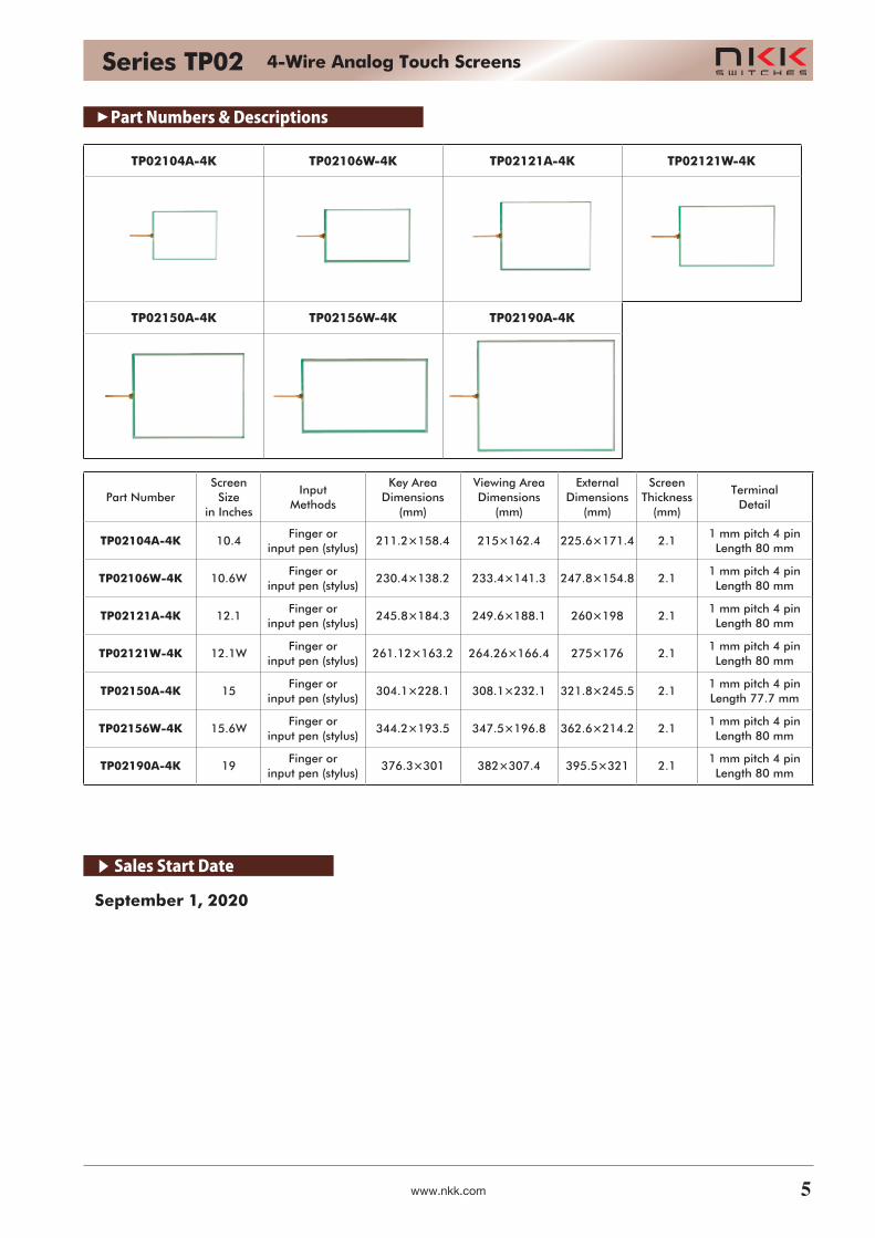
TP02104A-4K TP02106W-4K TP02121A-4K TP02121W-4K
TP02150A-4K TP02156W-4K TP02190A-4K
Part NumberScreen
Size in Inches
Input Methods
Key Area Dimensions
(mm)
Viewing Area Dimensions
(mm)
External Dimensions
(mm)
Screen Thickness
(mm)
Terminal Detail
TP02104A-4K 10.4Finger or
input pen (stylus)211.2×158.4 215×162.4 225.6×171.4 2.1
1 mm pitch 4 pinLength 80 mm
TP02106W-4K 10.6WFinger or
input pen (stylus)230.4×138.2 233.4×141.3 247.8×154.8 2.1
1 mm pitch 4 pinLength 80 mm
TP02121A-4K 12.1Finger or
input pen (stylus)245.8×184.3 249.6×188.1 260×198 2.1
1 mm pitch 4 pinLength 80 mm
TP02121W-4K 12.1WFinger or
input pen (stylus)261.12×163.2 264.26×166.4 275×176 2.1
1 mm pitch 4 pinLength 80 mm
TP02150A-4K 15Finger or
input pen (stylus)304.1×228.1 308.1×232.1 321.8×245.5 2.1
1 mm pitch 4 pinLength 77.7 mm
TP02156W-4K 15.6WFinger or
input pen (stylus)344.2×193.5 347.5×196.8 362.6×214.2 2.1
1 mm pitch 4 pinLength 80 mm
TP02190A-4K 19Finger or
input pen (stylus)376.3×301 382×307.4 395.5×321 2.1
1 mm pitch 4 pinLength 80 mm
▲
Part Numbers & Descriptions
5
Series TP02 4-Wire Analog Touch Screens
www.nkk.com

▲
General Specifications
6
Series TP02 4-Wire Analog Touch Screens
www.nkk.com
ModelDimension
A (mm)Dimension
B (mm)Dimension
C (mm)Dimension
D (mm)Dimension
E (mm)Dimension
F (mm)Dimension
G (mm)
TP02106AW-4K 247.8±0.3 233.4 230.4 138.2 141.3 154.8±0.3 125.3
TP02121AW-4K 275±0.3 264.26 261.12 163.2 166.4 176±0.3 138.89
TP02156AW-4K 362.6±0.3 347.5 344.2 193.5 196.8 214.2±0.3 181.3
10±1(65)
Reinforcement Film
TerminalNumber
(15)
80±1
5±1
41
Details of Tail End
5 ±
0.1
(0.5)
G
FED
ABC
Center of Active Area
XRILE X
Y LO
UPY
(1.5
) (Ai
r Ven
t)
0.3 ±
0.05 Contact Side
(Metal Plating)
Reinforcement Tail
Reinforcement Film Top Electrode
Bottom Electrode
0.7 ±
0.05
5±1
1×3=
3 ±
0.05
2.1 ±
0.2
Specifying circuit
YUP, YLO : Bottom Electrode ContactXLE, XRI : Top Electrode Contact
Pins Signal
1 YUP
2 YLO
3 XLE
4 XRI
YUP
14
YLO
XLE XRI

▲
General Specifications
7
Series TP02 4-Wire Analog Touch Screens
www.nkk.com
ModelDimension
A (mm)Dimension
B (mm)Dimension
C (mm)Dimension
D (mm)Dimension
E (mm)Dimension
F (mm)Dimension
G (mm)
TP02104A-4K 225.6±0.3 215 211.2 158.4 162.4 171.4±0.3 114.1
TP02121A-4K 260±0.3 249.6 245.8 184.3 188.1 198±0.3 131.5
TP02150A-4K 321.8±0.3 308.1 304.1 228.1 232.1 245.5±0.3 162.5
TP02190A-4K 395.5±0.3 382 376.3 301 307.4 321±0.3 198.1
5 ±
0.1
(0.5)
0.7 ±
0.05
5±1
1×3=
3 ±
0.05
41
XRILE X
YLO
UPY
)(1.5
) (Ai
r Ven
t)
10±1(65)
Reinforcement Film
TerminalNumber
(15)
0.3 ±
0.05 Contact Side
(Metal Plating)
Reinforcement Tail
Reinforcement Film Top Electrode
Bottom Electrode
80±1
5±1
G
FED
ABC
Center of Active Area
2.1 ±
0.2
Details of Tail End
Specifying circuit
YUP, YLO : Bottom Electrode ContactXLE, XRI : Top Electrode Contact
Pins Signal
1 YUP
2 YLO
3 XLE
4 XRI
YUP
14
YLO
XLE XRI

▲
Control Board/Device Driver for Single Touch Screens
Combining an analog touch screen with a control board device driver on a computer enables you to perform the same operations as you would with a mouse simply by touching the touch screen.
Control Board
Model Interface Type
TP02CS04CKS RS232C 4-wire system (FPC tail)
TP02CU04CKS USB 4-wire system (FPC tail)
Maximum Rating
Items SymbolsRated value
Unit NotesMin Max
Supply voltage
VCC -0.3 +5.5 [V]
Input voltage
VTP — VCC [V] Touch screen input
*VRS -15 +15 [V] RS232C
Operating temperature
TOPR -20 +70 [ºC] No condensation
Storage temperature
TSTG -25 +85 [ºC] No condensation
*VRS: For RS232C compatible models only
Recommended Operation Conditions
Items SymbolsRated value
Unit NotesMin Typ Max
Supply voltage
VCC +4.75 +5 +5.25 [V]
Operating temperature
TOPR -20 — +70 [ºC] No condensation
Basic Specifications
Items
TP02CS04CKS TP02CU04CKS
Interface RS232C standard USB 2.0 Full Speed
Clock 16 MHz 16 MHz
Power supply 5.0 V 5.0 V (USB bus power)
Resolution 10 bits 10 bits
Current consumption 40 mA or less 100 mA or less
Communication speed 9600 bps
Communication formatData length: 8 bitsParity bit: NoneStop bit: 1
USB compatible control board (sold separately)
System Configuration (for USB compatible system)
Products handled by NKK Switches Co., Ltd.
Touch screen connector
Computer monitor
Install device driver
USB header connector
IC for analog touch screen detection (available separately)
USB connection cable
Personal computer
Analog transparent touch screen
Touch screen connector
Install device driver
IC for analog touch screen detection
(available separately)
System Configuration (RS232C compatible)
Products handled by NKK Switches Co., Ltd.
AT713 connector with RS232C communication cord
RS232C compatible control board
Computer monitorAT714 connector with power supply cord (sold separately)
(sold separately)(sold separately)
5 V power supply header connector
5 V DC power supply
Personal computer
Analog transparent touch screen
RS232C header connector
▲
Device Driver for Single Touch Screens
• For one-touch wiring, the RS232C control board comes with an analog-type 4-wire touch screen connector, an RS232C header connector, and a 5 V power supply header connector. Receptacle connectors integrated with RS232C cords (AT713) and receptacle connectors integrated with 5 V power supply cords (AT714) are available as options.
* Refer to the product specifications before using the TP02CS04CKS/TP02CU04CKS. To obtain product specifications, please contact our sales office.
* Please contact our sales office for inquiries regarding detection ICs for single touch screens.
< Device driver >
Supported operating systems: Windows 7/8/10
Windows XPe CE* Windows is a registered trademark of Microsoft Corporation in the United States.
Function: Emulation software lets users perform operations
via touch screens in place of a mouse.
How to obtain the driver
To download/obtain drivers, sign up on the NKK
homepage or create a user account.
8
Series TP02 4-Wire Analog Touch Screens
www.nkk.com
▲
Control Board for Single Touch Screens
TP02CS04CKS (RS232C compatible)
CN1 4-Wire analog touch screen connector (4-pin)
Pins Symbol Terminal name
1 Y0For analog touch screen YUP or YLO
2 Y1
3 X0For analog touch screen XRI or XLE
4 X1
CN2 RS232C header connector (3-pin)
Control board side Computer side
Pins Symbol Terminal nameConnection terminal
name
1 RD Received data (IN) Sent data
2 SD Sent data (OUT) Received data
3 GND GND GND
CN3 Power supply header connector (2-pin)
Pins Symbol Terminal name
1 VCC Power supply voltage
2 GND GND
Pin No.
Contact surfaceTouch screen tail insertion direction
(1.3
)
(5.6
)
1.6
(5.5
)
(17)
37 30
65
57
4X3.3Lot markings
CN3
Pin No.
Pin No.
TP02-C 04CKSS
CN1
CN2
Model name
TP02CU04CKS (USB compatible)
CN1 4-Wire analog touch screen connector (4-pin)
Pins Symbol Terminal name
1 Y0For analog touch screen YUP or YLO
2 Y1
3 X0For analog touch screen XRI or XLE
4 X1
CN4 USB header connector (5-pin)
Pins Symbol Terminal name
1 VCC USB VCC
2 D- USB D-3 D+ USB D+4 GND USB GND
5 GND Shield GNDContact surface
Touch screen tail insertion direction
(3.9
5)
1.6
(4.5
)
37 30
65
57
TP02-C 04CKSU
Lot markings
Pin No.
CN1
Pin No.
Model name
4X3.3
CN4
Receptacle connector with RS232C cord (AT713)The AT713 is a receptacle connector integrated with a cord
used to connect the TP02CS04CKS control board to the PC
for RS232C communications. The length of the cord can be
specified by the customer. Excludes connector for PC side.
Receptacle connector with power cord (AT714)The AT714 is a receptacle connector integrated with a cord
used to connect the TP02CS04CKS control board to the
power supply. The length of the cord can be specified by the
customer.
0+50500
321
Wire colorPin No.BlackYellowBlue
0+50500
BlackRed
Pin No. Wire color21
9
Series TP02 4-Wire Analog Touch Screens
www.nkk.com

Control Board Handling Precautions• This product is not guaranteed to operate when combined
with a touch screen manufactured by any company other than NKK Switches.
• Be careful of static electricity when handling this product, and ensure workers and working areas where this product is handled are earthed.
• Do not turn on the power supply to this product until it is connected to both the host and touch screen.
• When connecting or disconnecting the CN1 connector of this product and touch screen tail section, be sure that the CN1 connector slider is pulled back, and refrain from connecting or disconnecting more than 10 times.
• Never attempt to modify this product.• The content of this product may be changed at the
manufacturer’s discretion for improvement purposes without prior notification.
• Do not use commands other than those prescribed in the specifications with this product.
• NKK Switches cannot accept any responsibility whatsoever for any damages that occur through the use of this product.
• The tail used to connect the touch screen unit and control board is susceptible to noise, and should therefore be installed as far away as possible from noise sources (LCD drive inverter, etc.).
• This product is covered under warranty for 1 year from the date of purchase.
Precautions for Installation• Make sure that the case or housing does not place
unnecessary stress on the product causing it to distort.• The tail section is the weakest part of the product and may
disconnect easily. Therefore, do not pull on or place stress on the tail section.
• Do not place excessive stress (sufficient to leave a bend line) on the tail section. Doing so may cause disconnection or increased resistance value.
• When installing glass products in particular, be sure to consider vibration and impact during installation.
• Install the touch screen securely so there is no looseness. Looseness may cause detection to become unstable. In particular, looseness has an adverse effect on detection performance of analog types during operation.
• Make sure there is no burring, etc. at the edges of the case and housing. Burring may cause misoperation. Furthermore, ensure that the edges of the case and housing do not enter the key area. Doing so may cause misoperation due to the edges of the case or housing.
• Leave a space (approx. 0.5 mm) between the case or housing and top electrode to ensure there is no differential shrinkage in the case, housing or top electrode, and no effects from distortion or deformation. When installing buffer material in the space, make sure that the top electrode is not forcibly pushed. Forcibly pushing the top electrode or fixing with double-sided tape, etc., may cause the top electrode to distort or flex, which has an adverse effect on the external appearance and functionality of the product. Install buffer material more than 0.6 mm to the inside of the A section.
• In cases where external pressure may be placed on the periphery during operation such as the case or housing section being held by hand, make sure that the touch screen is not input due to distortion of the edges of the case or housing.
• When fixing the touch screen in place, fix it using the bottom section such as by fixing it to the LCD. Fixing the top electrode to the case or housing with double-sided tape, etc. causes stress to be placed on the connection between the top and bottom electrodes, which may cause damage or distortion to the film or malfunctions.
• Some products have an air vent installed to ensure that the inner and outer pressure of the touch screen are the same. Make sure that this is not blocked when installing. Furthermore, ensure that liquids such as water and oil do not enter the product through the air vent or product exterior (connection section between the top and bottom electrodes).
• Avoid any situation where air pressure from a device attached to the touch screen could pass through the air vent and cause the top electrode to swell. Doing so may affect the product such as reducing the lifespan of the product. Furthermore, reducing the pressure in the touch screen through the air vent may cause interference fringe or constant input to occur.
• Please note that moisture from condensation, etc. on the tail connection section or edges may result in migration, causing short circuit failure to occur.
Handling Precautions• When unpacking the product, make sure the product is facing
in the correct vertical/horizontal orientation. Furthermore, glass edges have not been chamfered and may be sharp. Be sure to wear gloves when handling the products to avoid cuts.
• Do not use a clamp to lift or pull the tail section. Doing so may result in damage to the tail connection section.
• Wear gloves or fingerstalls to prevent the fingerprints or dirt from getting onto the product.
• When holding the product, hold it outside of the range of the visible area.
• To remove dirt from the surface of the product, wipe gently with a soft cloth soaked in ethanol. Do not use anything other than ethanol.
• When storing the product, wrap it in the same packaging as when it was purchased and within the temperature and humidity conditions prescribed in the specifications.
• Do not store the product in an acidic environment or near other corrosive gases.
• Do not store the product in locations where condensation may occur.
• Do not stack products or place other items on the products, as doing so places excess load on the products, which may result in deformation or bending of the products or scratches to the edges of the products.
• The product has a protective film attached. Do not remove this film until immediately before use to prevent the product from becoming scratched, etc. However, storing the product with the protective film attached for prolonged periods may result in the adhesive from the protective film becoming attached to the product.
Precautions for Operation• Do not operate the product with anything other than your
finger or a specialized input pen (commercially available polyacetal pen). In particular, do not use sharp objects such as a ballpoint pen or mechanical pencil. Doing so may cause scratches to the surface, malfunctions and cracked glass.
• The area between the visible area and key area is structurally weak. Do not rub harshly with a pen, etc.
(Continued on next page)
▲
Instructions
A
Appr
ox. 0
.5 m
m
Case/HousingCushioning
Adhesive Layer
Fixing Material such as Double-Sided Tape
0.6 mm Minimum
Visible AreaArticle Area
LCD, etc.Bottom Electrode (Glass)
Top Electrode (Film)
When burring occursWhen A section is supported
10
Series TP02 4-Wire Analog Touch Screens
www.nkk.com
Design Precautions• The input position of analog type products may become
misaligned due to resistance value differences between individual products, or changes to the resistance value due to age deterioration. Be sure to enable calibration using both hardware and software to calibrate the input position.
• When installed onto a display device such as an LCD, noise generated by the display device may cause malfunction. Implement noise countermeasures such as connecting the frame of the display device to ground.
• The contact resistance of the product changes when pressed by a finger or pen. Ensure that data is read when the contact resistance is stable, such as by ignoring data read when the contact resistance is unstable.
• Data becomes broken on the dot spacer of analog type products when used for drawing lines, etc., and must be corrected using software.
• Be sure to evaluate sufficiently when using double-sided tape or adhesive to attach the top electrode to the surface sheet. Distortion, etc. of the top electrode or surface sheet may have an adverse effect on functionality.
Precautions for Use• Products are guaranteed based on the evaluation of
product standards within the moisture tolerance and usage temperature range, but are not guaranteed to operate perpetually at this temperature.
• Touch screens have individual differences. Therefore, calibration data from one touch screen should not be applied to other touch screens, and calibration should be implemented for each touch screen.
• If the connector is removed and reconnected from the tail after calibration, perform calibration again.
• The prescribed specifications are a guarantee of product quality on a single touch screen. When using the product, be sure to confirm and evaluate performance when attached to your own products.
11
Series TP02 4-Wire Analog Touch Screens
www.nkk.com

Published September 1, 2020
* Specifications presented here are subject to change without prior notice. Check with our sales office for the latest specifications.
5.7" 5.7"6.5" 6.5"8.4" 8.4"10.4" 10.4"
10.6" 10.6"
10.6"10.6"
10.4"10.4"
12.1" 12.1"
12.1" 12.1"
12.1"12.1"
12.1"12.1"
15" 15"
15.6" 15.6"
15.6"15.6"
15"15"
19" 19"
19" 19"
Broadening the World of Touch Screens with PreciselyDesigned Resistive Film from a Specialist in Industrial Switches
NKK Suppliesa Wide Range ofTouch Screensto Meet the Needs
of All DifferentCustomers
Series FT, 4-Wire Analog, Printed Tail Series FT, 4-Wire Analog, FPC Tail
Series TP02 4-Wire AnalogFor operation that feels light to the touch For motion-sensitive operation
For a wide range of sizes and excellent cost performance
For high contact reliability
Series TP02 4-Wire Analog
IC
IC IC
4:3 4:3
4:3 4:3
Control Board
Control Board Control Board
WideWide
Wide Wide
5.7"
Series FT DigitalIf dedicated IC is not required
10.4" 12.1" 15"
Series FT 5-Wire/8-Wire AnalogFor high durability
4:3
ICControl Board※ The 8-wire analog typeis custommade. All sizes of the 4-wire type support an 8-wire conversion tail.
NKK Touch Screens
Published October 23, 2017
* Specifications presented here are subject to change without notice. Check with our staff for the latest specifications.
NKK SWITCHES CO., LTD. http://www.nkk.com E-mail: [email protected]
715-1 Unane, Takatsu-ku, Kawasaki-shi, 213-8553 Japan TEL: +81 44 813 8001 FAX: +81 44 813 8031
* Control boards and detection ICs for multi-touch functionality are available only in combination with touch screens. For more information, please contact our sales office.