light sources based on optical-scale accelerators
TRANSCRIPT

Light sources based on optical-scale accelerators
Gil TravishParticle Beam Physics LaboratoryUCLA Department of Physics & Astronomy
Input from...Claudio Pellegrini, Sven Reiche, Chris Seers, Chris McGuinness, Eric Colby, Joel England, Josh McNeur
Material stolen from... lots of people including C. Brau, J. Jarvis, T. Plettner

I want to thank the organizers for the opportunity
< 10 days
Eric Bruce
Me
10
HC-1060
laser light
electron beam
non-functional technology
Make a light source!
talk length = ƒ(t)

Can you build an iPad sized light source?

Should you build it?

Optical-scale dielectric-structures promise GeV/m gradients and naturally short bunches
+ very short pulses+ very high repetition rate+/- low charge- no track record- limited R&D work! The red-headed stepchild of AA
Gradients x10-x100 metalStructural control of fieldsMany possible geometries
Scalable fabrication
Tolerances:PWFA: ~300nmLWFA: ~30nmMAP: ~10nm

Basically, an FEL or ICS source has an injector, accelerator, radiator, and x-ray beamline.
DESY
SLAC- LCLS
! =12"
#u fcaw2$
% & '
( ) * 2 IIA+ x+ y
,
- .
/
0 1
13
Lg =!u
4 3"#
!"
"<< #
Energy spread limit
kp =4! I"IA A
<< 2ku#"
Space charge limit
Psat =1.6!Pbeam =1.6mc2
e!" I

The choice of accelerator technology impacts the possible light source configurations...
RF Optical
Gradient
Energy gain per period
Repetition Rate
Charge per Bunch
Bunch Length
10-100 MeV/m 1-10 GeV/m
1 MeV 1 keV
100 Hz 10-100 MHz
0.1 - 1+ nC 0.01-1 pC
1-100 ps 1-100 fs
key: charge and time scale; not gradient
McGuinness

... the undulator technology has at least as much impact on the FEL design.
PM Micro/Pulsed RF Optical
Period
Parameter
Gap
Status
>1 cm 0.1 - 1 mm 0.1-1 cm 1-20µm
1-10 <1 ~1 ~1
5 mm 1 mm 1+ cm 20-100µm?
Mature some SC work stalled paper
!opt " 3# n$4%&Lg
Focusing is an addition issue:

An example of a soft x-ray FEL-based source reveals the need for new undulator approaches
Parameter Value
Wavelength 6 nm
Beam energy 25.5 MeV
Energy spread 10-4
Emittance (norm.) 0.06 µm (doh!)
Charge 1 pC (whew!)
Peak current 750 A
Undulator parameter 1
Undulator period 20 µm
Focusing betafunction ~ 3 mm
Gain length 500 µm
FEL parameter ~3 x 10⁻³
Saturation length 6 mm (LOL)
x-ray flux per bunch ~5 x 10⁸
Lcoop/σL<1: 1-2 spikes
106 electrons; 108 photons
Pellegrini and Travish

A laser undulator for the 20µm case requires guiding or LLNL class lasers
Magic 20µm laser(similar for 10µm case)
for au=1need
EL= 35JPL ~ 1TW
Beating lasers800 nm + 1µm
for au=1need
EL= 8J x 2PL < 1TW
ZR =
πw02
λL
2LU = 12mm
w0 ~ 330µm w0 ~ 70µm
A hard x-ray FEL source using optical period undulator would be too low energy to function wellAn ICS-based hard x-ray source could produce tolerable fluxes if laser guiding works

We need to develop four critical technologies to make the iPad sized Light Source
1.Ultra low emittance injectors2. Optical-scale accelerators3. Micron-period undulators4. Laser guiding
PSI
LBNL
KyotoTeramobile

Low charge, high brightness injectors

Conventional RF photoinjectors are a viable source of low-charge, low-emittance beams
LCLS injector@ 20 pCachieved
0.13µm emittance
At ~1 pC, we need <0.01µm (10 nm)
emittances
What’s the problem?Preservation of nm emittancesLaser technology(MHz repetition rates)Injection into optical structures

Electron microscopes achieve the requisite emittances, albeit at very low current
Field and photo-assisted field emission work well
Needle cathode work is showing the way
Brau & Jarvis

Injection into a sub-micron aperture and a sub-ps bucket is a concern
Final focus typeAsymmetric emittances
IFEL pre-bunchingDielectric Injector
E. Colby
ε yε x
≈ 50
D. Edwards, et al., XX Linac Conference, (2000)
IFEL
Flat beam
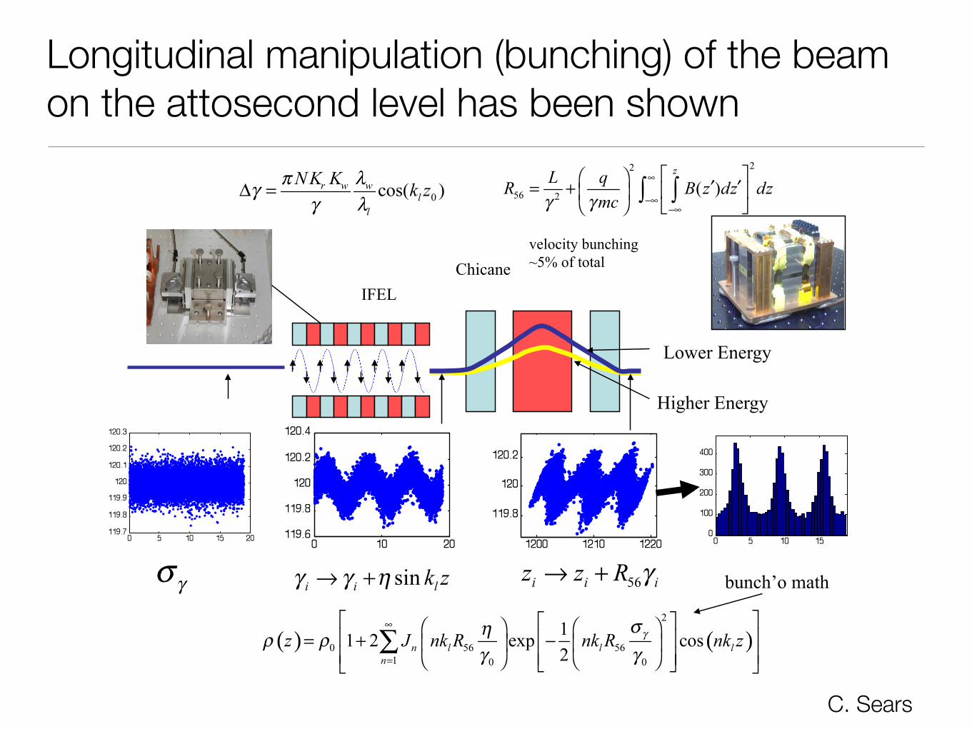
Longitudinal manipulation (bunching) of the beam on the attosecond level has been shown
bunch’o math
IFEL Chicane
Lower Energy
Higher Energy
velocity bunching ~5% of total
C. Sears

Integrating the injector and optical scale accelerator may be the best path
laser light
electron beam
Ultrafast Electron Pulses from a Tungsten Tip Triggered by Low-Power Femtosecond Laser PulsesPeter Hommelhoff, Catherine Kealhofer, and Mark A. KasevichPRL 97, 247402 (2006)

Creating low beta optical-scale structures is hard. Really hard.
John Breuer, Christopher M. S. Sears, Tomas Plettner, and Peter Hommelhoff
100 MeV/m @ 30nm from grating!"#$%&'"()
*+)
,-'&./#0)1-2+()
!"#"$% &'()*+%,-./% 0(1+*%,-./% 23+'$(3#%
!"# $%"#
&"# $%"#
%'"# $""#
%'"# $("#
%'"# $")#
%'"# $*"#
%'"# )!#
low ß MAP
All dielectric design needs work

Optical-scale accelerator structures

Here at SLAC, the E-163 AARD team is producing a set of laser-driven dielectric micro-accelerators
10 µm
HC-1060 Fiber
4 Layer Structure (10/08)
2 Layer Structure (6/08)
PBG
Woodpile

PBG-fiber-based structures afford large apertures and scalability to HEP-length structures
X. E. Lin “Photonic bandgap fiber accelerator,” PRSTAB 4, 051301 (2001)input port!
absorbing boundary!
HFSS: custom dielectric waveguide coupler
Efficient coupling to the accelerating mode of a PBG fiber is complicated by various issues:➡overmoded: coupling to other modes drains away input power➡extra modes are lossy and difficult to simulate➡initial simulation results from overlap with accelerating mode: ~
12%
~2.5 GV/m
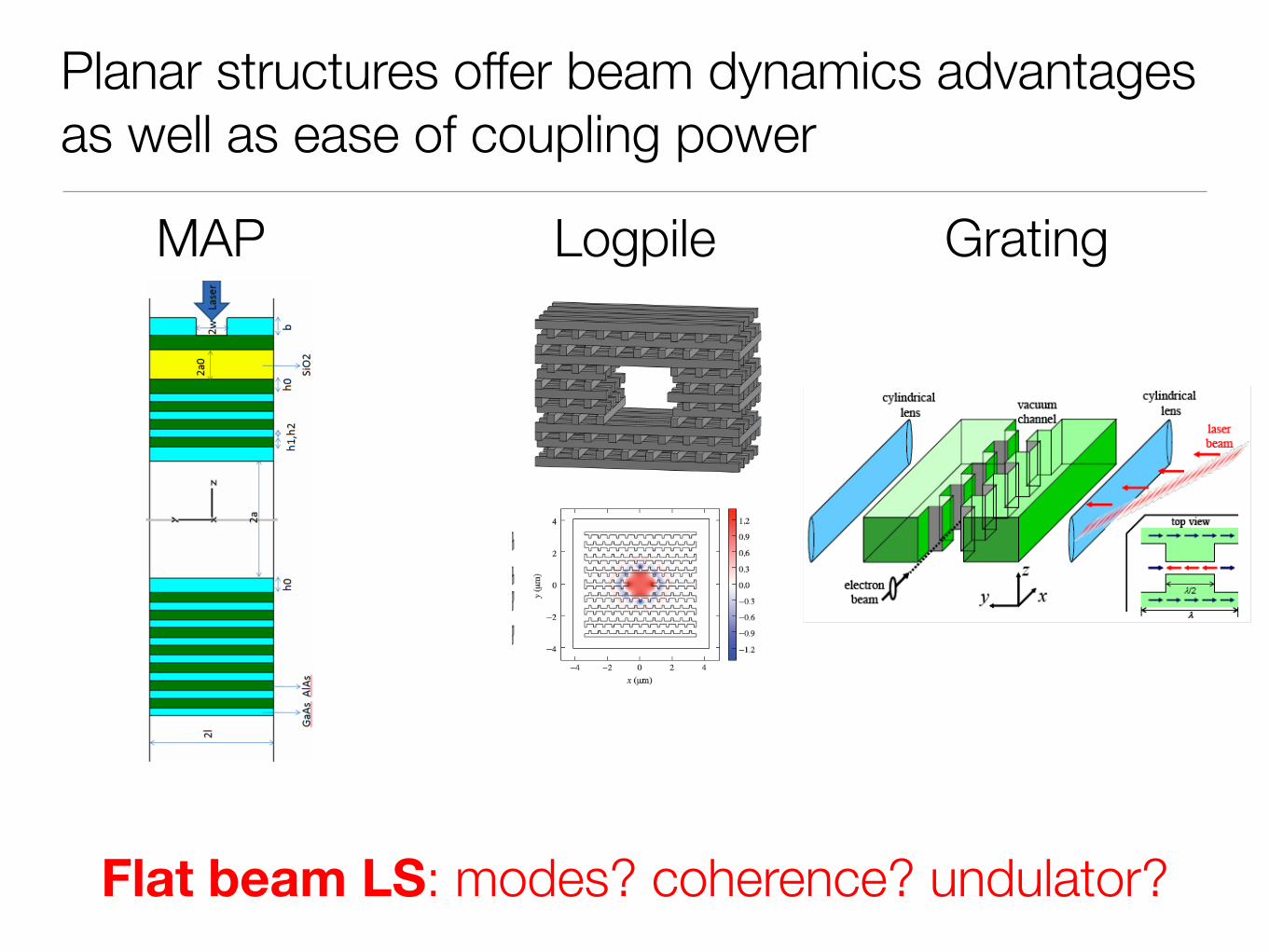
Planar structures offer beam dynamics advantages as well as ease of coupling power
Flat beam LS: modes? coherence? undulator?
MAP Logpile Grating

The MAP structure consists of a diffractive optic coupling structure and a partial reflector

The Micro Accelerator Platform (MAP) is undergoing intense simulation and fabrication study
e-
!"#"$% &'()*+%,-./% 0(1+*%,-./% 23+'$(3#%
!""# $%&#
&""# $%&#
'""# $&"#
'""# $("#
'""# $")#
'""# $!"#
'""# $")#
relativistic structure nearing fabrication-ready design

We are planning a ß=1 MAP beam de/acceleration experiment here at E163
SBIR collaboration with

The log-pile structure is being fabricated and offers an intermediate gradient solution
Gradient221 MeV/m @ 1.55µm
FabricationAmenable to higher
damage thresholdsTunabilityCouplingImpedence C. McGuinness

The Stanford grating structure is non-resonant and might support >10GeV/m
Materials near beam = easy to make the fields; bad for wakefields
Non resonant = 10 fs pulses; but complex coupling and synchronization
Plettner, et al., PAC 2007

These planar structures are modular and scalable
low wakefields
easy power coupling “easy” to scale & stage
flat beams
//>50µm

Breaking News AlertThe New York TimesTue, February 23, 2010 -- 3:08 PM ET-----
Toyota Executive Says Recall Might 'Not Totally' Solve Accelerator Problems
He doesn’t know the half of it!

Example: focusing issues in the MAP
Alternating Phase Focusing
periodically modulating the position of the coupling slot
!"#$%&$'()!
*+',-!.//012$'/0!"#$%&$'()!
34/502!!60127!"08)!
-9:;! -<=;! ->>9! >-?;!
-9:;! -<=! -:! ??-;!
-9:;! -<@;! -AB! @@-?!
-9:;! -<@! ?-?! BB-?!
-9;! -<=;! ->:! >-9!
-:! -<=;! -9B! :-9;!
-:;! -<=;! -9:! ??!
-A! -<=;! -:B! ?=!
bucket depth is impossibly limited
Initial analysis

Ultra-short period undulators
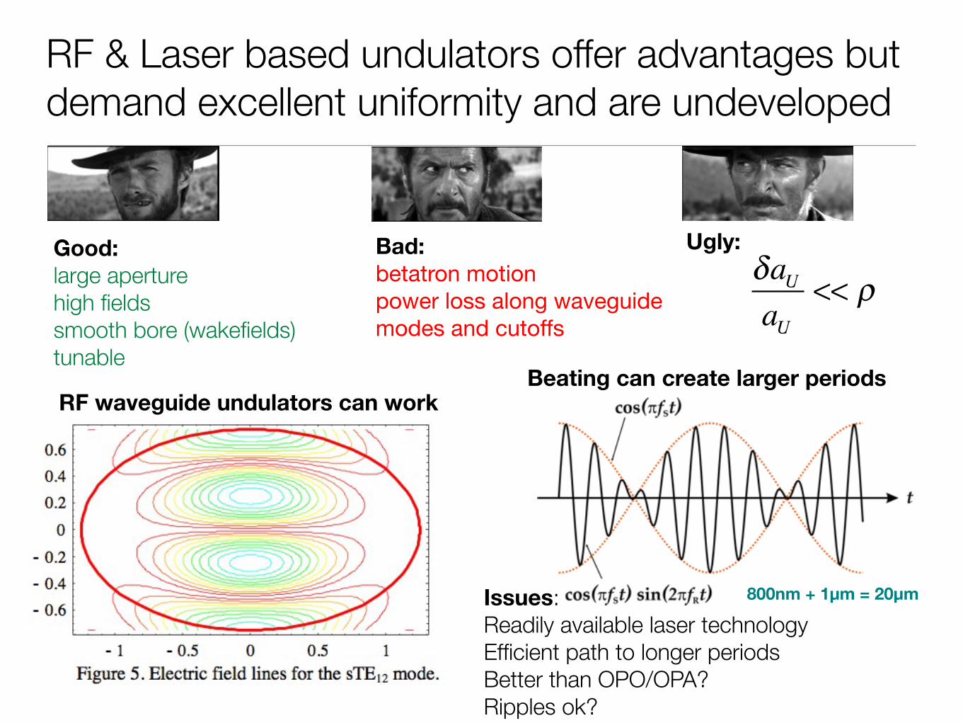
RF & Laser based undulators offer advantages but demand excellent uniformity and are undeveloped
δaUaU
<< ρGood:large aperturehigh fieldssmooth bore (wakefields)tunable
Ugly:
Beating can create larger periodsRF waveguide undulators can work
Bad:betatron motionpower loss along waveguidemodes and cutoffs
Issues:Readily available laser technologyEfficient path to longer periodsBetter than OPO/OPA?Ripples ok?
800nm + 1µm = 20µm

A grating based undulator can produce an intermediate-period device
Plettner and Byer, Phys. Rev. ST Accel. Beams 11, 030704 (2008)Barriers:Smith Purcell parasitic radiationAttosecond pulses and synchronizationLow fields?Period limit? (300µm)
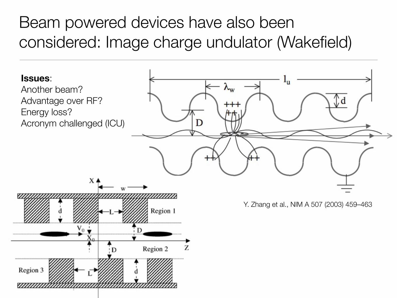
Beam powered devices have also been considered: Image charge undulator (Wakefield)
Y. Zhang et al., NIM A 507 (2003) 459–463
Issues:Another beam?Advantage over RF?Energy loss?Acronym challenged (ICU)

Laser guiding and laser technology

Guiding of the laser reduces the effects of diffraction and the Gouy phase shift
In practice, the fiber (waveguide) will be overmoded
R
g λ ≈ 1µm
On the other hand, a very small bore is required to obtain significant enhancement from guiding. We take
2R
g= 20 µm
The naive flux enhancement factor is simply
2w0
2Rg
⎛
⎝⎜⎜
⎞
⎠⎟⎟
2
= 4
Propagating the electron beam through the tube is necessary:
σ =
εnβγ
=ε
nL
γ
Electron beam transmission will be very challenging at low energies. There are many additional considerations such as vacuum, breakdown, plasma formation, etc. The brightness is enhanced further as the
bandwidth may be reduced.
2w
0
L
LASER
2R
g
ELECTRONS
!
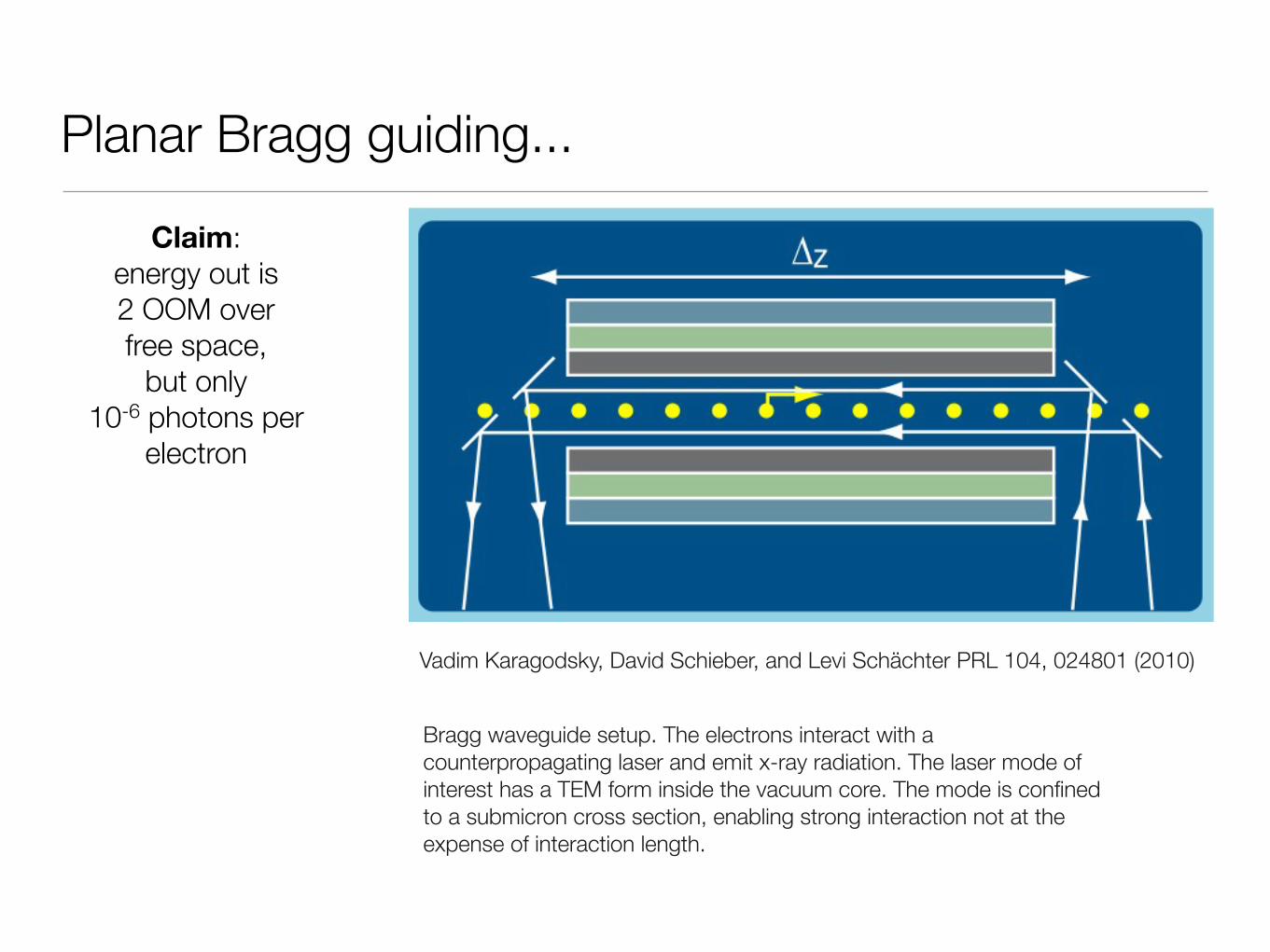
Planar Bragg guiding...
Vadim Karagodsky, David Schieber, and Levi Schächter PRL 104, 024801 (2010)
Bragg waveguide setup. The electrons interact with a counterpropagating laser and emit x-ray radiation. The laser mode of interest has a TEM form inside the vacuum core. The mode is confined to a submicron cross section, enabling strong interaction not at the expense of interaction length.
Claim:energy out is2 OOM overfree space,
but only10-6 photons per
electron

Guiding of the (soft) x-rays is also possible
!
r
2R
g
2!
c
!
cL
For the guided source, the phase space is at most
2θ
c2R
g
The phase space reduction factor is
2θc2L
4θcR
g
=θ
cL
2Rg
=1
Nzz
Equivalent phase space area:
(smallest ellipse isat least x2 bigger)
θ
cL 2R
g
assuming
!
r
2Rg
2!
c
!
cL
2θc2L
Unguided Guided
Guiding in optical accelerator driven ICS is
interesting:
short pulse = higher damage threshold
high rep rate = less laser energy per pulse
fields in guide ~ fields in accelerator

Conclusions

A soft x-ray light source powered entirely by lasers and on a laptop scale seems possible
Parameter Value
Wavelength 6 nm
Beam energy 25.5 MeV
Emittance (norm.) 0.06 µm (doh!)
Charge 1 pC (whew!)
Undulator parameter 1
Undulator period 20 µm
FEL parameter ~3 x 10⁻³
Saturation length 6 mm (LOL)
x-ray flux per bunch ~5 x 10⁸
Pellegrini and Travish

We have the opportunity to develop a suite of on-chip particle beam tools
all using laser-driven dielectric structure
guns
monolithic structures
undulators
coherent THz/x-ray sourcesIFEL accelerator
sub-relativistic structures
muons, protons, ions
deflecting cavities
ultra-fast sources
focusing
ICS Gamma-Ray Source
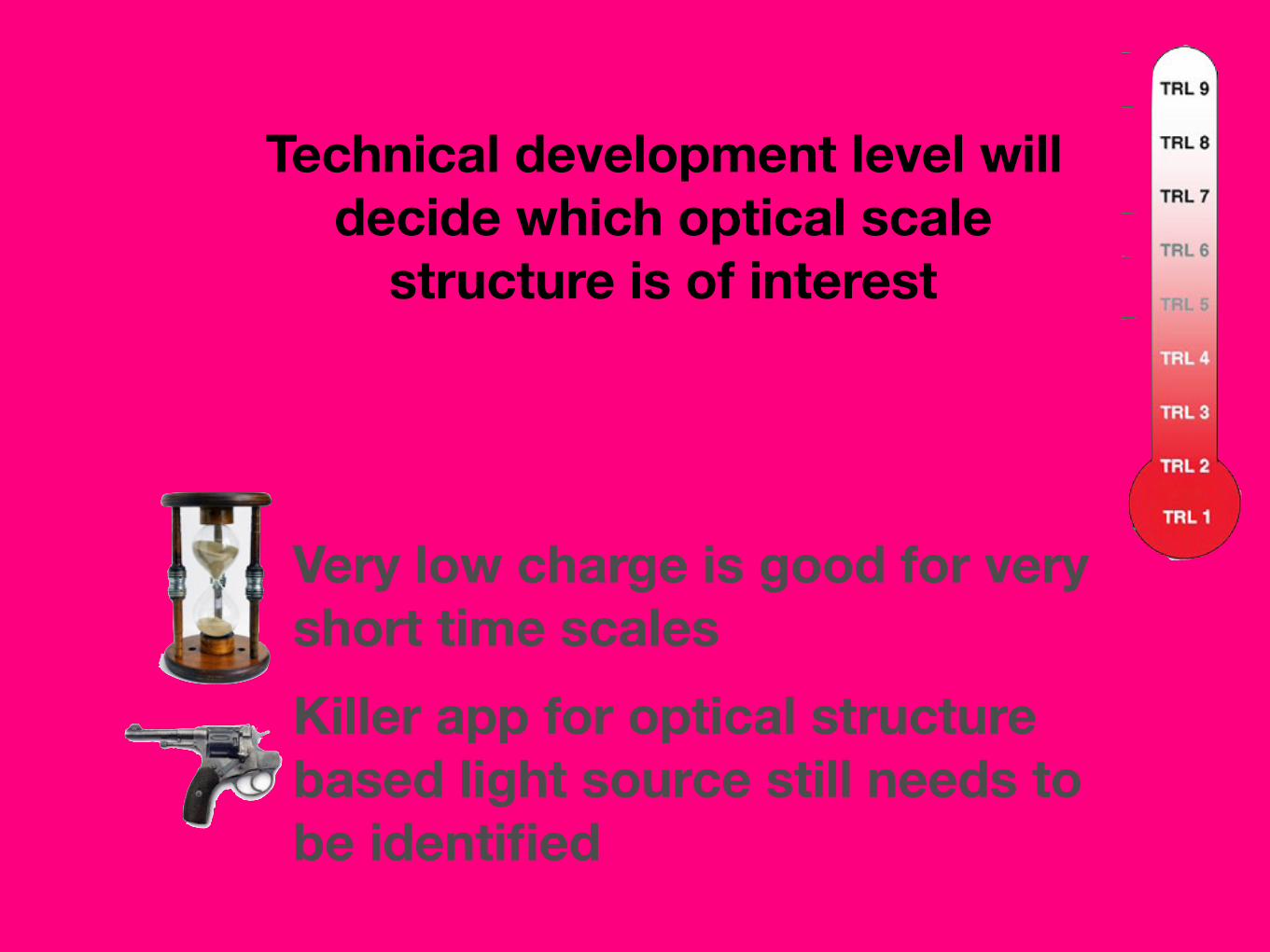
Very low charge is good for very short time scales
Killer app for optical structure based light source still needs to be identified
Technical development level will decide which optical scale
structure is of interest

predictionA laser “add-on box” to up-convert to x-rays and based on an optical-scale accelerator
will be available in 10 years