light scattering studies on the morphology and deformation mechanism of poly(tetramethylene...
TRANSCRIPT

Macromolecules 1982, 15, 193-202 193
Table I11 Comparison of Nonequal Force Constants for
Poly(g1ycine I ) and p-Poly(L-alanine) force constant ( G ~ Y I),
5.043 4.409 5.840 4.564 0.1 25 1.400 0.687 0.715 0.517
-0.150 0.000
-0.040
P - ( Ala )n 4.523 4.160 5.674 4.4628 0.150 1.033 0.5259 0.765 0.627 0.000 0.100 0.000
0.0065 0.038 f(CCaHa,CO ob) 0.100 0.150 f(NH.. 0 ib,NH ob) 0.000 -0.039 f(NH ob,CN t ) -0.1677 -0.1477
the lowest frequency A species mode, which has not yet been observed. In (Gly I), this force constant determines the splitting between infrared- and Raman-active CH2 bending modes.) The changes in f(NH) and f(H-0) are obviously necessitated by the difference in hydrogen bond strength between the two structures. The changes in the other force constants are undoubtedly due mainly to the presence of the CH3 side chain but probably also to the small differences in backbone angles between (Gly I), and @-(Ala),. In any case, these force constants are related mainly to the Ca atom, which is not surprising in terms of the influence of the side chain on the local charge dis- tribution. This effect is also manifested by the significant mixing of side-chain modes (CH, rock, C"CS stretch, CS bend, and C"CS torsion) with backbone modes, a situation which is not as true in the case of (Gly I),. Thus, (Ala), should serve as a better model for the vibrations of the polypeptide chain in proteins.
Conclusions
The availability of the spectrum of @-(Ala-ND),, as well as an improved transferable force field for (Gly I),,l has enabled us to achieve a significant improvement in the force field and band assignments for APPS (Ala),. This now provides a more secure basis for the vibrational analysis of other polypeptide chain structures as well as for the development of an approximate force field3 for the calculation of the normal modes of larger molecules.
Acknowledgment. This research was supported by National Science Foundation Grants PCM-7921652 and DMR-7800753. A.M.D. expresses appreciation to the Macromolecular Research Center for fellowship support.
References and Notes (1) Dwivedi, A. M.; Krimm, S. Macromolecules, preceding paper
in this issue. (2) Moore, W. H.; Krimm, S. Biopolymers 1976, 15, 2465. (3) Dwivedi, A. M.; Krimm, S., to be published. (4) Arnott, S.; Dover, S. D.; Elliott, A. J. Mol. Biol. 1967,30,201. (5) Colonna-Cesari, F.; Premilat, S.; Lotz, B. J. Mol. Biol. 1974,87,
181. (6) Moore, W. H.; Krimm, S. Biopolymers 1976, 15, 2439. (7) Krimm, S.; Abe, Y. h o c . Natl. Acad. Sci. U.S.A. 1972, 69,
2788. (8) Moore, W. H.; Krimm, S. Proc. Natl. Acad. Sci. U.S.A. 1975,
72, 4933. (9) Fanconi, B. Biopolymers 1973, 12, 2759.
(10) Frushour, B. G.; Koenig, J. L. Biopolymers 1974, 13, 455. (11) Elliott, A. Proc. R. SOC. London, Ser. A 1954, 226, 408. (12) Itoh, K.; Nakahara, T.; Shimanouchi, T.; Oya, M.; Uno, K.;
Iwakura, Y. Biopolymers 1968,6, 1759. (13) Frushour. B. G.: Painter. P. C.: Koenie. J. L. J. Macromol. Sci.. . ,
Rev. Macromol. Chem.'1976,'C15, 25: (14) Hsu, S. L.; Moore, W. H.; Krimm, S. Biopolymers 1976, 15,
151.7. (15) Krimm, S.; Bandekar, J. Biopolymers 1980, 19, 1. (16) Pouchert, C. J. "The Aldrich Library of Infrared Spectra";
Aldrich Chemical Co.: Milwaukee, Wisc., spectrum no. 294C. (17) Krimm, S.; Dwivedi, A. M. J. Raman Spectrosc., in press.
Light Scattering Studies on the Morphology and Deformation Mechanism of Poly(tetramethy1ene oxide)-Poly(tetramethy1ene terephthalate) Block Polymer1 Masaru Matsuo,* Keiko Geshi, Akiyo Moriyama, and Chie Sawatari Department of Clothing Science, Faculty of Home Economics, Nara Women's University, Nara 630, Japan. Received August 5, 1980
ABSTRACT The morphology and deformation mechanism in poly(tetramethy1ene oxide)-poly(tetramethy1ene terephthalate) block polymers were studied by small-angle light scattering, polarized microscopy, and bire- fringence experiments. A series of experiments was carried out using specimens with a relatively high concentration of soft rubbery segments. On the basis of the experimental results, two models were proposed in terms of the morphology and the deformation mechanism of the spherulitic texture. The H, light scattering patterns were theoretically calculated for the two models. One of them is associated with an orientation disorder of rodlike lamellae with respect to the spherulitic radius, and the other with an affine deformation mode of a perfect spherulite. The patterns observed were well accounted for by the results calculated.
I. Introduction There have been several reports2-' on the morphology
and deformation of segmented polymers synthesized by combining blocks or segments of two dissimilar homo- polymers to form a polymer chain, in which one component is characterized as a rubbery or soft segment with a rela- tively low glass transition temperature and the other as a hard segment with a glassy-amorphous or semicrystalline nature. There is currently considerable interest in the
0024-9297/82/2215-0193$01.25/0
fine-structure and physical properties of these polymers. The morphology of diblock and triblock copolymers made from styrene and isoprene cast from several solvents has been shown to consist of spheres, rods, or sheets of one component dispersed in a continuous matrix of the oth- er.*-ll
Kawai et al., studied the morphology and deformation mechanism of spherulitic textures in segmented poly(ur- ethaneureas). They concluded that the observed orien-
0 1982 American Chemical Society

194 Matsuo et al.
tation behavior may be explained in terms of two different mechanisms. Thus, at relatively small elongations, the crystalline lamellae were postulated as orientation units floating in a matrix of soft segments, while at relatively large elongation, the oriented lamellae were postulated to disintegrate into small fragments.
In the case of segmented polyether-polyester block co- polymers, there have been several recent publication^.^-^ This kind of copolymer consists of random sequences of amorphous poly(tetramethy1ene oxide) (PTMEG) soft segments and poly(tetramethy1ene terephthalate) (4GT) hard segments. Various attempts have been made to ac- count for the morphology and deformation mechanism by using electron microscopy, X-ray diffraction, and light scattering techniques. Cella4 studied the morphology of this polymer by electron microscopy. He suggested that the 4GT sequences crystallized as lamellar domains measuring approximately 100 A in width and up to several thousand angstroms in length, and these crystalline regions were continuous and highly interconnected. Seymour et ale6 found that the superstructures were present over a wide range of compositions. They reported that the direction of the optical axes was dependent on the average hard- block length and on the sample preparation method and, moreover, that chain folding within the lamellae was ev- idenced by the chemical etching technique.
Further detailed investigations of segmented poly- ether-polyester block copolymers were carried out by Cooper et aL67' on the basis of light scattering patterns, DSC thermograms, dynamic mechanical data, and infrared dichroism. An attempt was made to correlate the mor- phological information with the physical properties. They proposed that the light scattering patterns are consistent with the formation of positive spherulites, negative spherulites, and spherulites whose optical axis is at 45' to the radial direction depending on the copolymer compo- sition, casting solvent, and evaporation rate. They also inferred that the orientation mechanisms of the hard and soft segments were similar to those of the partially crys- talline segmented polyurethane elastomers. They postu- lated that the soft segments oriented almost reversibly in the stress direction, while the crystalline hard segments first oriented transverse to the stress direction and ex- hibited a high degree of orientational hysteresis.
In the present paper, the morphology and deformation of poly(tetramethy1ene terephthalate) hard segments and poly(tetramethy1ene oxide) soft segments are investigated mainly by using small-angle light scattering, and the ob- served patterns are compared with those calculated theo- retically. The models that have been presented by Cooper et al.l0 are utilized with some modification to calculate the scattering patterns. The scattering patterns observed expermentally for the undeformed spherulites are dis- cussed in comparison with the patterns calculated for the models associated with orientation disorder of hard-seg- ment blocks with respect to the spherulite radius. Moreover, the variation of the patterns with extension ratio is discussed in terms of an affine deformation mode. 11. Experimental Section
The soft and hard segments are given by
Macromolecules
hard segment soft segment
where x and y are averages depending on the polymerization conditions. The ratio of y to x is 1:3 and the total molecular weight is 40000-50000. Specimens were prepared by solvent casting and compression molding. The specimens obtained by solvent casting
I 1 0
I $ 5 0 1 . 0 L d I O 2 0 3 0 4 0 -50 10 20 3 0 4 0
Extension R a l f o 1 Extension Rat io X
Figure 1. Birefringent quantities of the solvent-cast film.
were formed as thin films several tens of microns in thickness by pouring about 0.5% solutions in 1,1,2-trichloroethane into a flat cell at 73 i 4 O C . The total orientation mode of the soft and hard segments was evaluated by using the birefringence technique. Deformation of spherulitic textures under uniaxial stretching at 90 "C was observed by small-angle light scattering. The Young's modulus at 25 "C was 4.87 X 1O1O dyn/cm2 at a constant rate of tensile strain of 67% /min. The specimen obtained by compression molding was molded at 200 "C for about 10 min at a pressure 140 kg/cm2. The film thickness was 3C-40 pm. The morphology was observed under the polarizing microscope. The light scattering patterns were observed for various elongation ratios during stretching at 65 "C.
111. Experimental Results and Discussion The total orientation behavior of the hard and soft
segments was investigated by the birefringence technique for the solvent-cast film under uniaxial stretching. The data obtained indicated a biaxial orientation mode of the segments as shown in Figure 1, in which A, and A2 are given by
A, = n3 - n2 (1) A2 = n3 - nl (2)
where n3, n2, and n, are refractive indices along the X,, X 2 , and X1 axes, respectively. The X , and X , axes cor- respond to the film normal and elongation directions, re- spectively. The symbol A, indicates the degree of mo- lecular orientation with respect to the stretching direction and A, the degree of molecular orientation with respect to the film surface. As can be seen in Figure 1, the mo- lecular chains assume not only a preferential orientation in the stretching direction but also a planar orientation. The increase of A2 may be presumed to be dependent upon the pronounced orientation of the benzene rings parallel to the film surface with increasing extension ratio.
Light scattering patterns were observed in order to study the deformation mechanism of spherulites in the cast film. The scattering patterns in the undeformed state were of the four-leaf clover type and were extended in the hori- zontal direction with increasing extenstion ratio. This mode is similar to that often observed for the deformation of polymer spherulites such as polyethylene under uniaxial stretching of the specimen. The four-leaf clover type pattern in the undeformed state is postulated to be due to scattering from three-dimensional spherulites or from two-dimensional spherulites whose optical axes orient randomly around its radius. This experimental result indicates that the molecular chains are randomly oriented, because the birefringent quantities A, and A2 were almost zero in the undeformed state as shown in Figure 1. This result is in goo! agreement with the fact that the orien- tation factor F&,l2 obtained by infrared dichroism analysis, was almost equal to zero.
Vol. 15, No. 1. January-February 1982
0 IO 20" u
( a ) ( b ) Fimm 2. €I. light scattering patterns fmm the specimen prepared by mmpreasion molding, showing different kinds of azimuthal dependence of wattered intensity with the maxima at (Zn + l)n/4 (n = (t3).
IO 30" 1111111 0 20
Light Scattering and PolyetherPolyester Copolymers 195
'OP -
Figure 3. H. light scattering petterns from the specunen prepared by compression molding, showing different kinds of azimuthal dependence of scattered intensity with the maxima at n r j 2 (n = (tR).
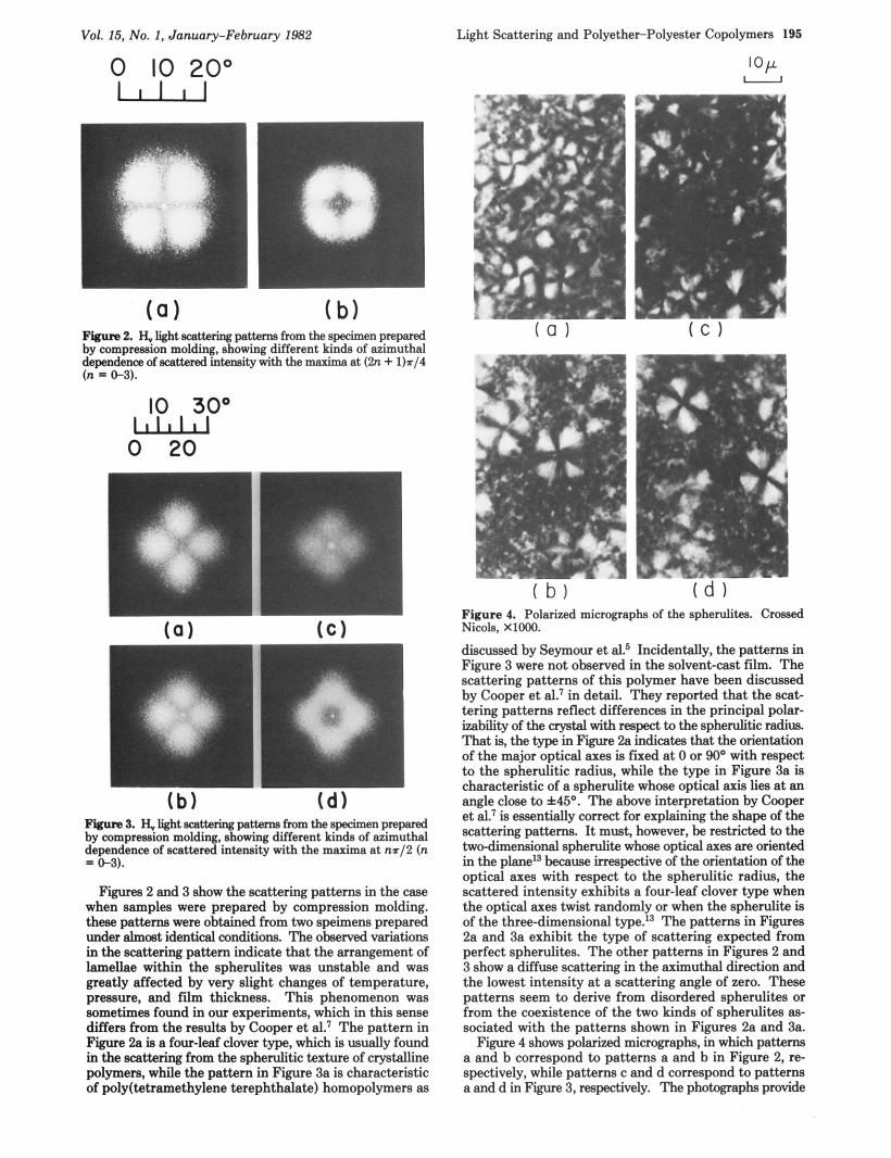
Figurea 2 and 3 show the scattering patterns in the case when samples were prepared by compression molding. these petterns were obtained from two speimens prepared under almost identical amditiom The ohserved variations in the scattering pattern indicate that the arrangement of lamellae within the spherulites waa unstable and waa greatly affected by very slight changes of temperature, pressure, and film thickness. This phenomenon was sometimes found in our experiments, which in this sense differs from the results by Cooper et al.' The pattern in Figure 2a is a four-leaf clover type, which is usually found in the scattering from the spherulitic texture of crystalline polymers, while the pattern in Figure 3a is characteristic of poly(tetramethy1ene terephthalate) homopolymers aa
Figure 4. Polarized micrographs of the spherulites. Crossed Nicole, XIOOO.
dwcuased by Seymour et alp Incidentally, the pat tern in Figure 3 were not observed in the solvent-cast film. The scattering patterns of this polymer have been discussed by Cooper et al.' in detail. They reported that the scat- tering patterns reflect differences in the principal polar- izabdity of the crystal with respect to the spherulitic radius. That is, the type in Figure 2a indica& that the orientation of the major optical axes is fixed a t 0 or 90' with respect to the spherulitic radius, while the type in Figure 3a is characteristic of a spherulite whose optical axis lies a t an angle close to f45'. The above interpretation by Cooper et al.7 is essentially correct for explaining the shape of the scattering patterns. It must, however, be restricted to the two-dimensional spherulite whose optical axes are oriented in the plane13 because irrespective of the orientation of the optical axes with respect to the spherulitic radius, the scattered intensity exhibits a four-leaf clover type when the optical axes twist randomly or when the spherulite is of the three-dimensional type.I3 The patterns in Figures 2a and 3a exhibit the type of scattering expected from perfect spherulites. The other patterns in Figures 2 and 3 show a diffuse Scattering in the aximuthal direction and the lowest intensity at a scattering angle of zero. These patterns seem to derive from disordered spherulites or from the coexistence of the two kinds of spherulites aa- sociated with the patterns shown in Figures 2a and 3a.
Figure 4 shows polarized micrographs, in which patterns a and b correspond to patterns a and h in Figure 2, re- spectively, while patterns c and d correspond to patterns a and d in Figure 3, respectively. The photographs provide

196 Matsuo et al. Macromolecules
lamellae with respect to the spherulitic radius. Our treatment seems to be somewhat complicated but is more realistic in terms of understanding the spherulitic mor- phology of this copolymer. The notation of Stein et al.17 has been followed.
The total scattering amplitude E of the spherulite is calculated by summing up the amplitude E, from each rod:
0 Figure 5. Schematic diagram of rodlike lamella with length L and width H surrounded by isotropic amorphous material.
information as to which of the patterns in Figure 2 derived from the scattering from the positive spherulites. By ob- servations under the polarized microscope, the patterns in Figure 3 were confirmed to correspond to the scattering from the two kinds of spherulites whose optical axes were fixed a t about +45 or -45O and could coexist with equal probability. On the other hand, the coexistence of the two kinds of spherulites in Figure 4a and Figure 4c was not observed in the position corresponding to the scattering patterns in Figures 2b and 3d under the sample prepara- tion conditions. The photographs in Figure 4b and Figure 4d exhibit spherulites with an indistinct orientation of internal structure. That is, spherulites are a kind of hybrid structure intermediate between the positive spherulite and the spherulite of which the optical axes were fixed at f45O. Moreover, it was confirmed that the scattering in Figures 2b and 3d was not due to the superposition of the two kinds of spherulites in Figure 4a and Figure 4c. Thus, we postulate that these structures are due to the unstable orientation of the crystal lamellae with respect to the spherulitic radius and that the observed scattering pat- terns, therefore, were due to the scattering from the dis- ordered spherulites. Hence, the difference of the azimuthal dependence of the scattered intensity was analyzed in terms of the magnitude of the disorder. The concept of the disordered spherulites was introduced by Stein et al.14-16 in order to resolve several discrepancies between observed and calculated patterns. They considered ori- entation disorder of the optical axes within a two-dimen- sional spherulite. The spherulites in Figure 4 are two- dimensional, the optical axes being oriented in the plane of the disk. This is quite different from the result of the solvent-cast film discussed before.
the lamellae were formed primarily by 4GT hard segments and the interradial amorphous regions are a nearly compatible mixture of the soft PTMEG segments and the uncrys- tallized 4GT hard segments. Figure 5 shows a schematic diagram proposed on the basis of their model in order to calculate H, light scattering patterns. In this diagram, the spherulite is composed of rods with length L and width H which correspond to the lamella formed by 4GT hard segments. This model was already utilized as an appli- cation of the general case for crystalline polymers proposed by Stein et al.I7 They derived the scattering patterns for a spherulitic array of anisotropic rodlike lamellae sur- rounded by isotropic amorphous material and investigated the effect of the internal spherulitic structure on the small-angle light scattering patterns. The present paper is concerned with the orientation disorder of the rodlike
In the models of Seymour et al.5 and Cooper et
E = C E , n
(3)
Now if we consider a rod which orients a t polar angle a with respect to the radial direction (V, direction) and whose center of gravity is a t position P, measured from the center of the spherulite, the scattering amplitude from a differential area element of this single rod is as follows:
(4) Here, It is 2a/A', A' is the wavelength of light in the me- dium, s is the propagation vector (so - s'), where so and s' are the unit incident and scattered beam vectors, re- spectively, 1, and h, are the coordinates of the interior of the rod in the length and the width directions, and p , is the scattering power per unit area, p n being given by p n = (M.0) =
G(sin [2(w0 + 7)] cos 2a + cos [2(w0 + 41 sin 2a) (5)
for H, scattering. 6 is the optical anisotropy, defined as the difference between the polarizabilities along and perpendicular to the optical axes. Then, the scattering amplitude E, from the single rod is given as follows:
dE, = p n exp[ik(r.s)] dl, dh, = p n exp[ik(P,.s)] exp[ik(r,-s)] dl, dh,
(M.0) exp[ik(P,-s)] ~ L 1 2 S H / 2 e ~ p [ i k ( r n ~ s ) ] -L/2 -HI2 dl, dh, (6)
Considering the symmetry of the spherulite, only the real terms count and eq 6 is rewritten as follows: E, =
G(sin [2(w0 + s)] cos 2a + cos [2(w0 + 711 sin 2a) X sin (ka,L/B) sin (kb,H/B)
ka,L/2 k b,H/2 cos [kr sin 8 cos (a - w ) ]
(7)
(8)
(9)
Substituting eq 7 into eq 3 and representing the summa- tion approximately by integration, we have
E ~ , = l / , d ~ ~ " ~ ~ ( s i n [2(w0 + 7)1 cos 2a +
where a, = sin 8 cos (a + 9 - p)
b, = sin 8 sin (a + 7 - w )
0 0 cos [2(w0 + 7)] sin 2a) X
cos [kr sin 8 cos (a - p ) ] X sin (ka,L/2) sin (kb,H/2)
ka,L/2 kb,H/2 r dr da (10)
The scattered intensity from this spherulite is given by the square of eq 10.
Now we shall consider the effect of the orientation disorder of the rodlike lamellae with respect to the spherulitic radius. Figure 6 shows a schematic diagram in which q1 and ?12 are the orientation angles with respect to the radii a t rl and r2, respectively, where r12 = rz - rl. The calculation may be carried out by using a correlation fluctuation approach similar to the treatment of the ori-

Vol. 15, No. 1, January-February 1982
x 3
Figure 6. Definition of the angles 7, and v2 in a two-rod system.
entation fluctuation of optical axes with respect to the spherulitic radius.14 For the sake of convenience, we as- sume H = 0. Therefore eq 10 is reduced to
E ~ , = '/,6XLzXJR{sin [2(w0 + 77)l cos 2a + cos [2(wn + 011 sin 2a) X - " . -
sin (kunL/2) kanL/2 cos [kr sin 0 cos (a - p ) ] r dr d a (11)
As an approximation, the sin (kanL/2)/(kanL/2) term in eq 11 may be expanded to
sin (kanL/2) sin x
ka,L/2 X = - - -
This method has been already used by Prud'Homme and Stein18 to study light scattering by correlated assemblies of anisotropic rods with random orientation. Equation 11 may be expanded by using eq 1 2 and if we let 5 = a - p, it follows that
cos [2(w0 + p + t)]SZX-'sin 25 cos (b cos 5 ) X -"
R = K 6 S [ S , sin [2(w0 + p ) ] J o ( b ) + ((S2 + S,) sin [2(00 + p ) ] cos 277 + (S2 - S,) cos [2(w0 + p)] sin 277)J2(b) +
( ( S , + S4) sin [2(w0 + p)] cos 417 + ( S , - S4) X cos [2(w0 + p)] sin 47)J4(b) + ( (S , + S,) sin [2(w0 +
p)] cos 617 + (S , - S,) cos [2(w0 + p ) sin 67/J6(b) + cos [2(w0 + p)] sin 8t)J8(b) + S,{sin [2(w0 +
p)] cos 107 + cos [2(w0 + p ) ] sin 10a)Jlo(b) + S&in
0
[(S, + s6) sin [2(w0 + p ) ] cos 8q + ( 8 4 - s6) X
[2(w0 + p ) ] cos 127 + cos [2(w0 + sin 12t)Jlz(b)lr dr (13)
Light Scattering and Polyether-Polyester Copolymers 197
B2 B4 15B6 7B8 105B'O s = - - + - - - +--- 3!.2, 5!.2, 7 ! ~ 2 ~ 9!.2, ll!.29
( 1 4 4 1
B = (aL/X') sin 0 (15)
b = kr sin 0 (16)
JJb) in eq 13 is the nth-order Bessel function. The value of the expanded series was determined by using 0.1 for the value of L/R in the actual calculation. Hence, we found that expansion by six terms fully suffices to approximate eq 11. In order to facilitate the calculation of the scattered intensity, we define the relation between 7, and q2 as follows:
91 = 770 + A1 (17)
7, = t o + A, (18)
where A, and A, are the fluctuation effects of the orien- tation of the lamellae at rl and r2, respectively, and A,, = A, - A, as in the method by Stein and Chu.14
The intensity may be formally calculated by squaring eq 13 prior to integration. The integral over rl and r2 may be replaced by an integral over r1 and r12, where r12 = r2 - rl. That is,
T,-COS 6 A 1 2 - + T4 COS 81112 + T5 COS lOA12 + T6 cos 12Alz)rl(rl + r12) dr12 dr, (19)
Now, the value of cos 2nA12 depends only upon the separation of the volume elements r12 and may be ex- pressed, according to the Stein-Stidham theory,lg in terms of an orientation correlation function
(20)
where a is a correlation distance of orientation disorder. Analytical expressions for the coefficients Ti (i = 0-6) in eq 19 may be represented as the nth-order Bessel function, and they are available as supplementary material (see supplementary material paragraph at the end of this pa- per). (cos 2nA1),, which appears in the coefficients Ti (i = 0-6), was taken outside the integral according to the method by Stein and Chu.14 As discussed by them, the term cos 2nAl varies randomly with rl so if one averages over all spherulites of the system, it will suffice to replace it with its average value (cos 2nAl),. Therefore, we have
f n = (COS 2nA12)rI2 = expl-n21r121/a/
(1 - n2(R/a) - exp(-n2R/a))
(21)
The coefficients Ai (i = 1-13), Bi (i = 1-23), Ci (i = 1-18), Di (i = 1-9), Ei (i = 1-9), Fi (i = 1-4), and Gi (i = 1-2) to calculate the coefficients Ti (i = 0-6) are represented as
2 ( n2R/ a),
(COS 2nAl),, = -
where

198 Matsuo et al. Macromolecules
I I I 4
0 5 10 15 20
W
Figure 7. Relative intensity at particular azimuthal angles of (2n + l )r /4 (n = 0-3) in the case of wo = 90" and vo = 0" (or wo = 90" and vo = 90°, or wo = 0" and 70 = 90°, or wo = 0" and v0 = 0") or nr/2 (n = 0-3) in the case of wo = 45" and Q,, = 0" (or
a function of Si (i = 1-6), wo, and v , and they are available as supplementary material.*l The quantity bi is given by
(22) Figure 7 shows the relative intensity as a function of W
(=2~R(sin 0) lX' ) at the particular angles p = (2n + 1 ) ~ / 4 (n = 0-3) at wo = 90" and qo = 0" (or wo = 90° and qo = 90°, or wo = 0" and qo = 90°, or wo = 0" and qo = 0") or p = nr/2 (n = 0-3) at wo = 45' and qo = 0" (or wo = 90" and qo = 45"). The calculated patterns for negative and positive spherulites give the same results and show the same tendencies as in the case where the optical axes are +45O or -45O with respect to the spherulitic radius. The scattered intensity has a maximum near W = 4 and is zero at W = 0 as does a perfect spherulite, but the peak be- comes broader with increasing R l a . The higher order maxima and minima in the intensity, which were found for a perfect spherulite at W > 4, became indistinct with increasing R la and the intensity curve decreased mono- tonically. This tendency was similar to the result of Stein and Chu.14
Figure 8 shows the scattering patterns calculated a t wo = 90" and qo = 0" (or wo = 90' and qo = 90°, or wo = Oo and qo = 90°, or wo = 0" and qo = 0") and Figure 9 shows those calculated at wo = 45" and qo = 0" (or wo = 90" and qo = 45"). At lower scattering angles, the disorder leads to a disturbance of the four-leaf clover type pattern as- sociated with the scattering from a perfect spherulite, and the scattering pattern becomes circular with increasing Rla. Comparing Figure 2 with Figure 8 and also Figure 3 with Figure 9, one observes that the calculated patterns are close to the observed ones when an appropriate value of R la is chosen. This suggests that the various types of patterns observed can be explained in terms of the orien- tation disorder of rodlike lamellae with respect to the spherulitic radius. In other words, for specimens prepared by compression molding, the orientation of the rodlike lamellae formed primarily by the poly(tetramethy1ene terephthalate) exhibits a fluctuation with respect to the spherulitic radius.
The stretched samples were found to be composed of a mixture of disordered and nearly perfect spherulites. In order to facilitate the investigation and avoid difficulties of interpretation, we have restricted the observation to perfect spherulites, and the scattering experiments were carried out in such a way that only the patterns from perfect spherulites were recorded. Figures 10 and 11 show the variations of the H, scattering patterns with stretching
~0 = 90" and 70 = 45").
bi = kri sin 0
( c ) R / o = O . l ( f ) R / a * 1 0 0
Figure 8. H, light scattering patterns calculated for the effect of orientation disorder in the case of wo = 90" and q0 = 0" (or wo = 90" and qo = 90°, or wo = 0" and 70 = go", or 00 = 0" and 70 = 00).
n* n* "
0'
( c ) R /a=O. l ( 1 ) R / a = 1 0 0
Figure 9. H, light scattering patterns calculated for the effect of orientation disorder in the case of wo = 45" and vo = 0" (or wo = 90" and 7o = 45").
for almost perfect spherulites. As can be seen in the fig- ures, the pattern in Figure 10a corresponds to that in Figure 2a, while the pattern in Figure l l a corresponds to that in Figure 3a. The change of the pattern in Figure 10 is typical of the behavior obtained experimentally from a

Vol. 15, No. 1, January-February 1982
0 IO 209 GG]
Light Scattering and Polyether-Polyester Copolymers 199
IO 30' LLLW 0 20
. , .
I b ) A = 1.2 ( f l x .2.5
f C 1 x = 1 5 191 A = 3 0
Figwe LO. H, light scattering patterns of the specimen prepared by compression molding with increasing extension ratios.
uniaxially deformed spherulitic crystalline texture as in deformed spherulites of polyethylene and polypropylene. Such patterns appeared in the specimen prepared by solvent casting. On the other hand, the change of the patterns in Figure 11 is similar to the results observed of Cooper et al.? Considering the change of the patterns in Figures 10 and 11, information ahout the orientation of crystal lamellae may he deduced from the fact that every specimen still has a 'four-leaf" pattern characteristic of a uniaxally deformed spherulitic crystalline texture irre- spective of the degree of stretching. This result suggests that the rodlike lamellae of perfect spherulites are quite stable during uniaxial stretching, being only slightly af- fected by the disintegration of the lamellae into less or- dered crystalline fragments. This enables us to draw a schematic diagram showing the deformation of the spherulite and the orientation of the lamellae within the spherulite.
Figure 12 shows that a rod with length L, initially or- iented a t a given angle a between the OX8 axis and the center of gravity of the rod, is deformed into a rod with length L' and oriented at a'. During the deformation process, the optical axes change their orientation from a + wo to a' + w' with respect to the stretching direction (OX, direction), and the rods change their orientation from qo to q' with respect to the spherulitic radius. The orien- tation of rods as well as optical axes was assumed to occur by affine deformation.
The total scattering amplitude E' of a deformed spherulite is calculated by summing up the amplitude E,' from each oriented rod:
E'= XE,' (23) n
f a 1 A ; I W
I t- -I i e ) A = ? O
( 9 1 A = 3 0 c I d 1 A = I e
Figure 11. H, light scattering pattern of the specimen prepared hy compression molding with increasing extension ratios.
X.
X. - Figure 12. Model denoting orientation of rod within spherulite aa well aa deformation of the spherulite.
The scattering amplitude from an element of this single oriented rod is dE,,' = p'(M'.O) exp[ik(P.'.s)] exp[ik(r,,'-s)] dr.' (24)
where where P,,' is the vector from the center of the spherulite to the center of gravity of an oriented rod. p' is the total scattering power of the oriented rod. The &e deformation of the spherulite leads to
P.' = P,,'(cm dk + sin a'j) = PJA, cos ak + A2 sin aj) (25)
where A, and A, are elongation ratios along and perpen- dicular to the stretching direction. According to the me- thod of Stein et al.,', it is then convenient to define an angle y such that

200 Matsuo et al. Macromolecules
X2 sin p
(A: sin2 p + X32 cos2 p)'12 sin X = (26)
A3 cos p cos y = (27)
(X22 sin2 p + cos2 p)'12
and a variable q such that
q = kP, sin 8(X22 sin2 p + cos2 p) (28)
in this case, we have k(P,'.s) = kP, sin e(X3 cos a cos p + X2 sin a sin p) =
where $ = a - y. It also follows that
P, dP, = ( R 2 / X 2 ) q dq
q cos $ (29)
(30)
where
X = kR sin 0(X22 sin2 p + X t cos2 p)'12 (31)
and we have 1,' = l,'(cos (7' + a')k + sin (7' + a')j)
= 4 ( X 3 cos (q + a)k + X2 sin (q + a)j) (32)
Now the scattering amplitude E,,' from the singly oriented rod is given by
L'/2 E,' = lL,,2dE,'
L'/2
-L'/2 = (M'mO) exp[ik(P,'.s)] 1 p' exp[ik(r,'.s)] dr,'
= (M'eO) exp[ik(P,'-s)]p0[sin('/,KL sin e [ & cos (a + q) cos p + X2 sin (a + q) sin p])]/[1/& sin 6[X3 cos (a
+ q) cos p + h2 sin (a + q) sin p]] (33)
where po is the total scattering power of the unoriented rod. Substituting eq 33 into eq 23, we may obtain the total amplitude E'of the deformed spherulite as the summation of E,', which may be approximated by integration. The result is rewritten, by considering the symmetry of the spherulite, as follows:
cos [k(P,'.s)][sin (l/zkL sin e[X3 cos (a + q) cos p + X2 sin (a + q) sin p])] / [ f / , k L sin e x
[A3 cos (a + q) cos p + X2 sin (a + p ) sin p]]P dP d a
= KIJx 1'" po(M'.O) X q=o x=o
cos (q cos $)[sin (y2kL sin @[A3 cos (a + q) cos p + X2 sin (a + q) sin p])]/[f/zkL sin e X
[A, cos (a + q) cos p + X2 sin (a + q) sin p ] ] q dq d a (34)
(35)
and (M'-O) is given, according to the affine orientation of optical axes, by
(M'eO) = '/ZS{X2X3 sin [2(w0 + q + C Y ) ] } / ( X ~ ~ sin2 (wo +
where
K1 = 1/2K COS p2No(R2/X2)
q + a) + cos2 (ao + q + a)) (36)
0' 30' 60"
90'
( a ) X.1.2
0' 30' €0'
90'
( b ) X.1.5
0' 30' 60'
SO' SO'
( c ) X=1.8
0' 30' 60' ._
90'
._
90'
( d ) X=2.0
Figure 13. H, light scattering patterns with increasing extension ratios calculated at oo = 90" and 7 = Oo.
Equation 34 is integrated over 4, $ being held constant. According to the method by Stein et al.,13 a function f($) is given by
1 x f($) = ssg=;os [ q cos $14 dq
cos (X cos $) - 1 sin ( X cos $1 x cos $ + (37)
Therefore, we obtain the amplitude of the deformed spherulite by numerical integration of eq 34 over the angle $. In this calculation, we have X = X3 and h3X2 = 1.
The patterns in Figure 13 were calculated from the square of the amplitude E as shown in eq 34 a t wo = 90" and q = 0" and those in Figure 14 at wo = 90" and q = 90". The former patterns correspond to the scattering from negative Spherulites and the latter patterns to that from positive spherulites. The H, theoretical patterns from the negative and positive spherulites are the same as in the undeformed state but they change with elongation. This difference in the H, patterns with increasing elongation ratio becomes very large in terms of the extension of scattering lobes in the horizontal direction. The extension of the scattering lobes in the case of the positive spherulites is not as large as that for the negative spherulites. The patterns in Figure 14 calculated for the positive spherulite are rather close to the observed ones in Figure 10, which is in agreement with the results of the polarized micro- graphs in Figure 4. This indicates that the information on the scattering from elongated samples allows us to postulate that in the specimens used in this experiment the spherulites are positive. The patterns in Figure 15 were calculated from the square of the amplitude E as shown in eq 34 at wo = 45" and qo = 0" and those in Figure 16 at wo = 90" and q = 45". The two kinds of patterns are the same in the undeformed state but change with ex-
- - (X cos $)2

Vol. 15, No. 1, January-February 1982
( a ) A-1.2
Figure 14. H, light scattering patterns with increasing extension ratios calculated at coo = 90' and 7 = 90'.
0' 30" 60'
90.
( a ) A-1.2
0' 30' 60'
9 0'
( C ) X.1.8
0. 30' 60'
90'
Figure 15. H, light scattering patterns with increasing extension ratios calculated at w,, = 45' and 7 = 0'.
tension. The scattering lobes in Figure 15 are extended in the horizontal direction with increasing extension ratios.
Light Scattering and Polyether-Polyester Copolymers 201
0' 30' 60'
90'
( d l X.2.0
Figure 16. H, light scattering patterns with increasing extension ratios calculated at wo = 90' and 7 = 45'.
This mode is close to the observed patterns in Figure 11. By constrast, the lobes in Figure 16 are extended but have four notches. These notches become pronounced with increasing extension ratio. According to the above results, we believe that the lamellar axes orient in the radial di- rection and that the optical axes orient a t 45' to the la- mellar axis within the rod in the undeformed state. In the above calculation of the H, scattering patterns, we have not considered the contribution of the interradial amor- phous regions, which are a mixture of PTMEG soft seg- ments and uncrystallized 4GT hard segments. This is, however, more or less correlated with the deformation mechanism of the spherulitic texture. Hence,the effect must be considered in future work, though the calculation when introducing the contribution of the amorphous re- gions is very complicated. The morphology and the de- formation mechanism of poly(tetramethy1ene oxide)- poly(tetramethy1ene terephthalate) block copolymers having different concentrations of hard segments will be discussed elsewhere.*O IV. Conclusions
The morphology and the deformation mechanism were investigated for poly(tetramethy1ene oxide)-poly(tetra- methylene terephthalate) block copolymers with a con- centration ratio of soft to hard segments of 1:3. When the solvent-cast film was uniaxially stretched, the total ori- entation of the hard and soft segments was observed by birefringence measurements. The results show that both of the segments oriented predominantly in the stretching direction, thus producing an approximately biaxial orien- tation mode with planar orientation of the benzene rings with respect to the film surface. In addition, the light scattering patterns exhibited a four-leaf clover type in the undeformed state and its lobes were extended in the horizontal direction with elongation.

202 Macromolecules 1982, 15, 202-204
On the other hand, when the sample was prepared by compression molding, the scattering patterns were of two types. One has maximum intensity at particular azimuthal angles (2n + 1)~/4 (n = 0-3). The other has maximum intensity a t n r / 2 (n = 0-3). Using a proper choice of the correlation distance parameter, theoretical calculations were carried out to explain the characteristic azimuthal dependence on the basis of a model associated with ori- entation disorder of the rodlike lamellae with respect to the spherulitic radius. The calculated pattern became circular with decreasing correlation distance. The calcu- lated results were close to the observed ones with a suitable choice of the parameter R / a . The scattering patterns at various extension ratios were investigated by assuming an affine deformation model of the spherulite. The calcula- tion was restricted to the scattering from a perfect spherulite. The results were rather close to the observed patterns in the case of two kinds of spherulites. That is, the one corresponded to a positive spherulite and the other to a spherulite whose lamellar axes orient in the radial direction and the optical axes orient a t 45O to lamellar axis.
Acknowledgment. We are indebted to Professor Co- oper of the Department of Chemical Engineering, Univ- ersity of Wisconsin, for his valuable comments and sug- gestions on the manuscript. Thanks are also due to Pro- fessor Kawai, Faculty of Engineering, Kyoto University, Dr. Masuko, Faculty of Engineering, Yamagata University, Dr. Ishihara, Katata Institute, Toyo-bo Co., Ltd., and Professor Kimura, Faculty of Science, Nara Women's University, for their helpful comments. We are also grateful to Dr. Manley, Department of Chemistry, McGill University, for his kind help with linguistic revisions of the manuscript.
Supplementary Material Available: A list of the coefficients Ti ( i = 0-6) in eq 19 (8 pages). Ordering information is given on any current masthead page.
References and Notes
Notes Ring-Opening Polymerization of Spiro(acy1oxy)phosphoranes Having a P-H Bond with the Use of a Proton-Trapping Agent SHIRO KOBAYASHI, TAK YUEN CHOW, and T A K E 0 SAEGUSA*
Department of Synthetic Chemistry, Faculty of Engineering, Kyoto University, Kyoto 606, Japan. Received February 2, 1981
Spiro(acy1oxy)phosphoranes (1) are new pentavalent phosphorus species, originally prepared by us. They are reactive monomers and give various types of phospho- rus-containing polymers (2).132 Polymerizations of 1 take place by heating, without added initiator.
2 // 0
1, X = 0, CH,
Spiro(acy1oxy)phosphoranes having a P-H bond (2- oxo-1,4,6,9-tetraoxa-5-phosphaspiro[4.4]nonanes 3) are
0024-9297/82/2215-0202$01.25/0
Presented in part at the 32nd Annual Meeting of Home Eco- nomics Science, Japan, Tokyo, Oct 1980. Cooper, S. L.; Tobolsky, A. T. J. Appl. Polym. Sci. 1968, 10, 1837. Kimura, I.; Ishihara, H.; Ono, H.; Yoshihara, N.; Nomura, S.; Kawai, H. Macromolecules 1974, 7, 355. Cella, R. J. J. Polym. Sci., Part C 1973, 42, 727. Seymour, R. W.; Overton, J. R.; Corley, L. S. Macromolecules 1975, 8, 331. Schen, M.; Mehra, U.; Niinomi, M.; Koberstein, J. T.; Cooper, S. L. J. Appl. Phys. 1974,45, 4182. Lilanoitku, A.; West, J. C.; Cooper, S. L. J . Mucromol. Sci., Phys. 1976, B12, 563. Matsuo, M.; Sagu, S.; Asai, H. Polymer 1969, 10, 79. Inoue, T.; Soen, T.; Kawai, H.; Kukatsu, M.; Kurata, M. J. Polym. Sci., Part B 1968, 6, 75. Inoue, T.; Soen, T.; Hashimoto, T.; Kawai, H. J . Polym. Sci., Part A-2 1969, 7, 1283. Inoue, T.; Soen, T.; Hashimoto, T.; Kawai, H. Macromolecules 1970, 3, 87. Nomura, S.; Kawai, H.; Kimura, I.; Kagiyama, M. J . Polym. Sci., Part A-2 1967, 5, 479. Clough, S.; van Aartsen, J. J.; Stein, R. S. J. Appl. Phys. 1965, 36, 3072. Stein, R. S.; Chu, W. J. Polym. Sei., Part A-2 1970, 8, 1137. Stein, R. S.; Hashimoto, T. J. Polym. Sei., Part A-2 1971, 9, 517. Hashimoto, T.; Stein, R. S. J. Polym. Sei., Part A-2 1971, 9, 1747. Prud'Homme, R. E.; Yoon, D.; Stein, R. S. J. Polym. Sei., Part
Prud'Homme, R. E.; Stein, R. S. J. Polym. Sci., Part A-2 1974, 12, 1085. Stein, R. S.; Stidham, S. N. J. Appl. Phys. 1964, 35, 42. Sawatari, C.; Muranaka, T.; Matsuo, M., in preparation. The coefficients Ti ( i = 0-6) in eq 19 are available as supple- mentary material. See supplementary material paragraph.
A-2 1973, 11, 1047.
known.3 We examined the polymerizability of 3 in order to obtain polyphosphonates having a P-H bond (4). It turned out, however, that 4 was not formed by simple heating of 3. The present paper reports a novel polym-
7
3
erization of 3 with the aid of the carbonyl compounds benzaldehyde, p-benzoquinone, and methyl acrylate. The function of these carbonyl compounds is to accept an acidic hydrogen ("proton-trapping agent").
Results and Discussion First, monomers 3a,b were prepared by a new ester-
exchange reaction; i.e., the reaction of 2-phenoxy-1,3,2- dioxaphospholane (5) with a-hydroxy acid 6 quantitatively gave 7 with liberation of phenol. Compound 7 is in equilibrium with 3 as shown by 31P NMR analysis; 3 is a
0 1982 American Chemical Society