light guide layout design tool
TRANSCRIPT

Light Guide Layout Design Tool

2
Abstract
With the advances in augmented and
mixed reality (AR & MR) technology,
lightguide devices have become the
object of increasing interest. To help the
optical engineer with the design of such
systems, VirtualLab Fusion offers several
systematic design tools that break down
the task into a controlled, step-by-step
process. In this use case we demonstrate
the capabilities of the Layout Design tool
to automatically generate “Hololens 1”-
type (1D-1D pupil expansion with linear
gratings) systems according to the
specifications of the user.

Open the AR & VR Layout Design Calculator
• The Layout Design tool is a special calculator in the Light Guide Toolbox Gold Edition.
• It is initialized in the Light Guides section within the Start ribbon of the main window.
3

Layout Design – Setup Parameters
?
• Field of view range (FOV)
• Position & orientation of
in- and outcoupling
region
• Thickness of waveguide
• Eye Pupil Expansion
(EPE) deflection anglein-couple
Region
out-couple
Region
4
120°90°

Layout Design – Calculated Parameters
incoupling
region
outcoupling
region
outcoupling region- grating period
- grating orientation
- lateral extension
EPE region - position and complex
shape
- grating orientation
- grating period
incoupling region- grating period
- lateral extension
5
EPE Region

Automatic Generation of Optical Setup with Lightguide
6
The Layout Design
tool will automatically
generate an Optical
Setup where the
position and
parameters of source,
component and
detectors are specified
according to the
parameters in the tool.
wavelength
information will
also be used to
calculate grating
parameters

Plane Wave Source Specifications
7
The Diameter of the
source is
automatically adjusted
in order to include a
necessary soft edge.
The Beam Size and
Distance Source to
Light Guide
parameters
determine the size
of the incoupler.

Scanning Source Specifications
8
All relevant source
parameters are
automatically adjusted in
both Plane Wave Source
and Scanning Source.
The range of entered
field of view (FOV) is
also considered for the
size of incoupler and
outcoupler if distance of
the source and eye relief
(outcoupler) are given.

Positioning of Component & Grating Regions
9
The position of the Light Guide
Component itself and the
grating regions on the
surfaces are automatically
adjusted according to the
given specifications.
The size and shape of the
expansion grating is
automatically calculated.
The position of the
incoupler is defined in
absolutely (in the CS
of the lightguide),
whereas the position of
the outcoupler is
defined relatively, with
respect to the position
of the incoupler.
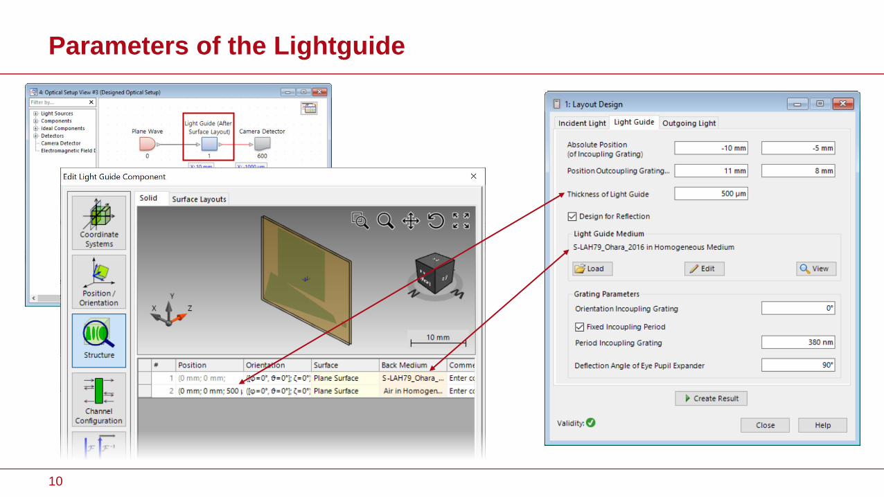
Parameters of the Lightguide
10

Design for Transmission or Reflection
11
The user can choose whether the lightguide should work in transmission or
reflection, means on which side the light is going to be outcoupled.
Note: Distance between source,
lightguide and detector are
increased for illustrational
purposes.

Parameters of Grating Regions
12
The period of the
expansion grating is
automatically
calculated.

Parameters of Grating Regions
13
Instead of defining a period for the incoupling grating, a
(minimum) desired mode density in the eye box can be
specified. This value is used to estimate an adequate
period of the incoupler.
3 mm

Deflection Angle Setting
14
The parameter Deflection Angle of Eye
Pupil Expander enables to modify the
diffraction angle at the EPE and thus
adjusts the positions and orientations
of the EPE and outcoupling grating
accordingly. This provides an
additional degree of freedom for
complex lightguide designs.
120° (Note: Position Outcoupling
Grating has been set to 19mm in x-
direction and 9mm in y-direction to
avoid overlap of the regions)
90°

Detector Settings
15
The position and window size of the detector
(Camera Detector by default) are specified by
the settings in the tool. Additional parameters
like sampling can be adjusted by the user if
needed. It is also possible to add additional
detectors into the system after the layout
design process has completed.
Corresponds to the
so-called “eye relief”.

Overview of Parameter Dependencies and Contributions
Parameter in Light Guide Calculated from:
Size of incoupler Beam Size, Distance Source to Light Guide, FOV
Period of incoupler • Period Incoupling Grating
• Desired Mode Density, Wavelength, Distance Source to Light
Guide, Thickness of Light Guide
Size of outcoupler Size eye box, Thickness of Light Guide, Distance Light Guide to Eye,
FOV, Beam Size
Period of outcoupler • Period Incoupling Grating
• Desired Mode Density, Wavelength, Distance Source to Light
Guide, Thickness of Light Guide
Shape of Eye Pupil Expander Deflection Angle of Eye Pupil Expander, position of incoupler and
outcoupler, Beam Size
Period of Eye Pupil Expander Deflection Angle of Eye Pupil Expander, Wavelength, period of
incoupler, FOV, Beam Size
16

Results
17
Alongside the Optical Setup, a k-Layout Visualization is automatically
generated for additional analysis of the device. More information on
this representation and the corresponding VirtualLab Fusion feature
can be found under:
k-Domain Layout Visualization

Document Information
www.LightTrans.com18
title Light Guide Layout Design Tool
document code LIG.0005
document version 1.0
software edition VirtualLab Fusion Advanced, Light Guide Toolbox Gold Edition
software version 2021.1 (Build 1.180)
category Feature Use Case
further reading
- k-Domain Layout Visualization
- Construction of a Light Guide
- Modeling of a “HoloLens 1”-Type Layout with Light Guide Component
- Flexible Region Definition
- Specification of Diffraction Orders and Efficiencies for Grating Regions
- Light Guide Design Tool