light d6 lengt fixtures tat can be oined to create continuous ros. for ros over 12 r fixtures ill be...
TRANSCRIPT
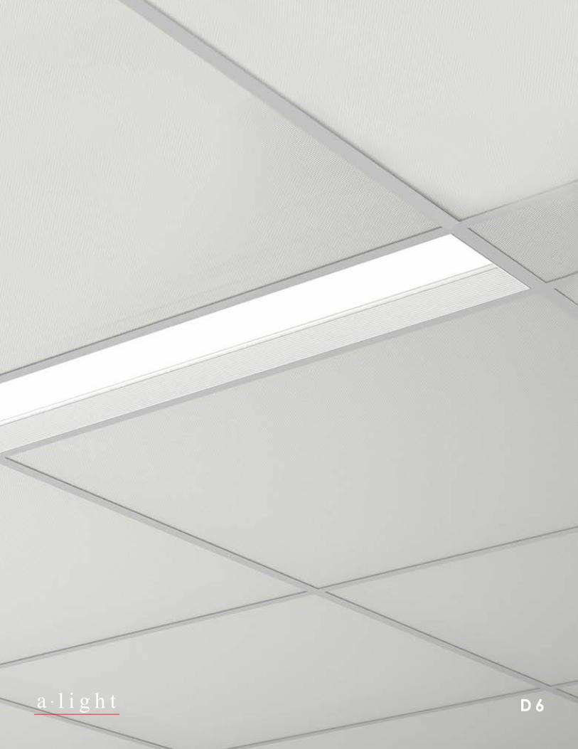
l i g h t D 6
6.00” O.C.
3.19”
3.51”
4.125” 3.51”
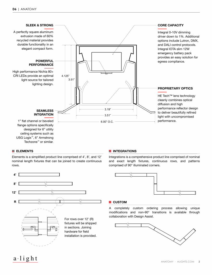
Integrations is a comprehensive product line comprised of nominal and exact length fixtures, continuous rows, and patterns comprised of 90° illuminated corners.
A completely custom ordering process allowing unique modifications and non-90° transitions is available through collaboration with Design Assist.
Elements is a simplified product line comprised of 4’, 8’, and 12’ nominal length fixtures that can be joined to create continuous rows.
For rows over 12’ (R) fixtures will be shipped in sections. Joining hardware for field installation is provided.
ELEMENTS
4’
8’
12’
R
INTEGRATIONS
CUSTOM
SLEEK & STRONG
A perfectly square aluminum extrusion made of 60%
recycled material provides durable functionality in an
elegant compact form.
POWERFULPERFORMANCE
High performance Nichia 80+ CRI LEDs provide an optimal
light source for tailored lighting design.
SEAMLESSINTGRATION
1” flat channel or beveled flange options specifically
designed for 6” utility ceiling systems such as
USG Logix™, 6” Armstrong Techzone™ or similar.
PROPRIETARY OPTICS
HE Tech™ lens technology cleanly combines optical diffusion and high performance reflector design to deliver beautifully refined light with uncompromised performance.
CORE CAPACITY
Integral 0-10V dimming driver down to 1%. Additional options include Lutron, DMX, and DALI control protocols. Integral IOTA slim 12W emergency battery pack provides an easy solution for egress compliance.
D6 | ANATOMY
ANATOMY · ALIGHTS.COM 2l i g h t
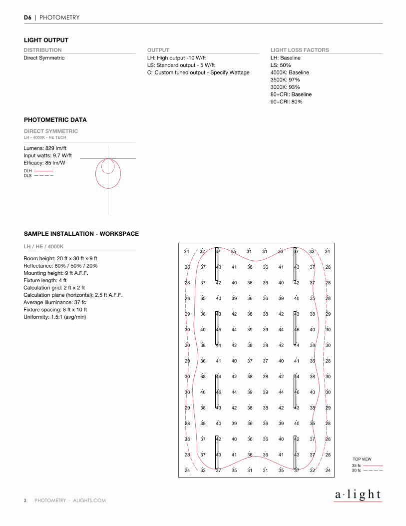
LIGHT OUTPUTDISTRIBUTIONDirect Symmetric
OUTPUTLH: High output -10 W/ftLS: Standard output - 5 W/ftC: Custom tuned output - Specify Wattage
LIGHT LOSS FACTORSLH: BaselineLS: 50%4000K: Baseline3500K: 97%3000K: 93%80+CRI: Baseline90+CRI: 80%
PHOTOMETRIC DATA
DLHDLS
DIRECT SYMMETRICLH - 4000K - HE TECH
Lumens: 829 lm/ftInput watts: 9.7 W/ftEfficacy: 85 lm/W
SAMPLE INSTALLATION - WORKSPACE
LH / HE / 4000K
Room height: 20 ft x 30 ft x 9 ftReflectance: 80% / 50% / 20%Mounting height: 9 ft A.F.F.Fixture length: 4 ftCalculation grid: 2 ft x 2 ftCalculation plane (horizontal): 2.5 ft A.F.F.Average Illuminance: 37 fcFixture spacing: 8 ft x 10 ftUniformity: 1.5:1 (avg/min)
TOP VIEW35 fc30 fc
29 38 43 42 38 38 42 43
28 35 40 39 36 36 39 40
28 37 42 40 36 36 40 42
28 37 43 41 36 36 41 43
24 32 37 35 31 31 35
30
283728 37 42 40 36 36 40 42
243224 32 37 35 31 31 35 37
283728 37 43 41 36 36 41 43
283528 35 40 39 36 36 39 40
293829 38 43 42 38 38 42 43
304030 40 46 44 39 39 44 46
3830 38 44 42 38 38 42 44
28
30
30
29
28
28
28
24
36
38
40
38
35
37
37
3237
29 36 41 40 37 37 40 41
30 38 44 42 38 38 42 44
30 40 46 44 39 39 44 46
D6 | PHOTOMETRY
l i g h t3 PHOTOMETRY · ALIGHTS.COM
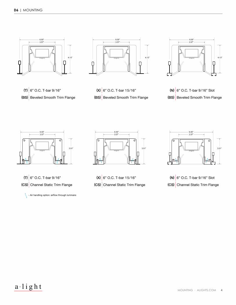
(T) | 6” O.C. T-bar 9/16”
(BS) | Beveled Smooth Trim Flange
- Air handling option: airflow through luminaire
(BS) | Beveled Smooth Trim Flange (BS) | Beveled Smooth Trim Flange
(X) | 6” O.C. T-bar 15/16” (N) | 6” O.C. T-bar 9/16” Slot
(T) | 6” O.C. T-bar 9/16”
(CS) | Channel Static Trim Flange (CS) | Channel Static Trim Flange (CS) | Channel Static Trim Flange
(X) | 6” O.C. T-bar 15/16” (N) | 6” O.C. T-bar 9/16” Slot
4.13”
3.51” 3.51” 3.51”
6.00” 3.57”
4.13”
6.00” 3.57”
4.13”
6.00” 3.57”
6.00” 3.57”
6.00” 3.57”
6.00”3.57”
D6 | MOUNTING
MOUNTING · ALIGHTS.COM 4l i g h t
D6 | TECHNICAL DATA
ALIGHTS.COM 6l i g h t
LINEAR DIMENSIONSElements - 4’, 8’, and 12’ nominal length individual fixtures that can be joined to create continuous row lengths.
Integrations - Nominal or exact lengths to the nearest 1/8th of an inch available as individual fixtures or joined to create continuous row lengths, minimum fixture lengths is 12 inches. Patterns comprised of 90 degree precisely welded fully illuminated corners provide a multitude of geometric options and architectural transitions.
Custom - Contact Design Assist for modifications to product not detailed within Elements or Integrations specification sheets.
OPTICSHE Tech™ patented high efficacy extruded diffuse acrylic lens technology with integrated opaque white reflector delivers superior lumen output with optimal uniform lens surface luminance for direct distribution.
LED LIGHT SOURCECustom manufactured linear board array uses high performance Nichia® LED in combination with a performance driven heat sink technology. Tested in accordance with LM79 and LM-80; L70>60,0000hr; operated at reduced output for high efficacy and lumen maintenance. 3000K, 3500K, and 4000K with 80+ CRI standard; other color temperatures and 90+ CRI available upon request, contact factory. LED color variation maintained at a 3-step MacAdam ellipse (SDCM 3x). LEDs are available in Low, Standard, and High outputs. Refer to photometry for delivered lumens. Custom output in the range of 25% to 125% of high output, contact factory.
LED DIMMING DRIVERFactory tuned constant current electronic 0-10V control dimming driver is standard. Specification grade dimming down to 1%. Driver life of 50,000 hrs with ambient operating temperature range of -30°C to 50°C, maximum case temperature of 75°C. Electrical specifications at maximum driver load: PF >0.9, THD <20%, >85% Efficiency. Other available drivers include Lutron Eco-system H-series (LDE1): Hi-lume™ 1% LED dimming driver with Soft On, Fade to Black; and DMX and DALI protocol drivers. Other Lutron and specialty drivers available, contact factory.
EMERGENCYThis luminaire is provided with a factory installed LED emergency lighting battery pack for both normal and emergency operation, 120-277v only. This fixture integrated unit contains long-life Ni- Cad recyclable battery, 24 hour charger, and converter circuit. Test switch and charge indicator provided. Test button to be remote located within 3 feet of the luminaire, by others in accordance with local code. Emergency mode provides constant power to a nominal 12W LED load for a period of 90 minutes, delivering 1200 lumens of unwavering illumination throughout the full 90 minute emergency duration. Unless otherwise specified, the emergency battery pack will illuminate one 2 foot end in the direct portion of the fixture.
Emergency circuiting provided as a separate circuit from normal power circuit according to NEC requirements, specify circuit length and location.
CONTROLSLow-profile integral occupancy and daylight sensors are available to deliver high performance control in an architecturally pleasing package.
Integral occupancy sensor - the sleek Wattstopper FS-205 modular plug-in system utilizes a RJ45 connector, low voltage cord, and power pack. Automatic on/off passive infrared (PIR) occupancy sensing control covers a range of 200 square feet for a specified 30 second to 30 minute time delay with an optional ambient daylight sensing function to hold lights off when specified adequate daylight level is sensed. Factory default time delay of 30 minutes and 120fc light level. Settings can be adjusted at the factory or easily in the field.
Integral daylight sensor - the sophisticated Wattstopper FD-301 is a low voltage controller using 0-10VDC input to automatically dim the electric lighting system based on daylight contribution in a 70° field of view to achieve a target illuminance using a sliding setpoint algorithm. This single zone “closed loop” daylight harvesting control system utilizes a RJ45 connector, low voltage cord, and power pack. One (1) LSR-301-S setup remote control to adjust target let levels is provided per order.
Combined occupancy and daylight sensing is achieved using both the FS-205 and FD-301 for more versatile control functionality including automatic on/off occupancy and daylight dimming response.
Other manufacturer controls may be available for product integration, contact factory.
MOUNTINGCommon recessed mounting options available. Contact factory for applications regarding modified recessed mounting conditions.
Flush Gypsum Flange. Raw aluminum flange is attached to blocking (by others), then mudded over and/or painted by installing contractor to provide a “flangeless” fixture appearance in recessed ceiling/wall applications.
Trim Flange. 1/2” wide visible powder coated flange, specify finish requirement. Fixture is mounted to structure using threaded rod (by others) or ceiling tie wires (provided). Use of a-clamp™ secures fixture trim and housing around ceiling/wall material. Use for any gypsum or hard ceiling/wall that requires a minimal flange covering the ceiling cut-out edge.
T-Bar/Grid Ceiling. 9/16” or 15/16” standard T-Bar or 9/16” slot ceiling. Raw aluminum flange sits on T-Bar and is concealed from view.
6” Armstrong Techzone™ / USG Logix™ or other 4” Utility Systems. 9/16” or 15/16” standard T-Bar or 9/16” slot ceiling. Suitable for use in 4” on-center standard or slot T-Bar systems. Approximate 1” wide visible side flanges create a seamless 4” slot condition, specify finish requirement.
STRUCTURERobust, high quality 60% recycled aluminum extruded housing. 0.040” thick aluminum internal gear trays. Flat or flanged aluminum end caps. Aluminum joiner brackets. 4 lbs/ft approximate fixture weight.
Air handling option provides 6.75 square inches of opening every foot. Only available with Channel Static trim flange.
FINISHElectrostatically applied powder coat finish. Standard finish options include alightanium™, satin white, and satin black. Other colors and custom finish options available, specify RAL# or contact factory regarding custom finish requirement.
LISTINGIC Rated for IC, Airtight, CCEA Ceilings. CCEA mark applied for Chicago Plenum applications. UL/CUL rated for Damp Locations. Tested in accordance with UL 1598 and certified to CEC/CSA C22.1, NEC, ANSI/NFPA 70, and NOM-001-SEDE.
WARRANTYLimited defect-free manufactured equipment warranty provided under normal use and proper storage for a period of one (1) year. LED products (LED boards and drivers) will be covered for a period of five (5) years.
LED MODULESHeavy-duty, milled aluminum plate module contains recessed cutouts for flush mounting of LED module (supplied). Specification and layout of modules and lamping per LED MODULE ADDENDUM.
7 TECHNICAL DATA · ALIGHTS.COM l i g h t
D6 | TECHNICAL DATA
8 LED MODULE ADDENDUM · D6 · ALIGHTS.COM l i g h t
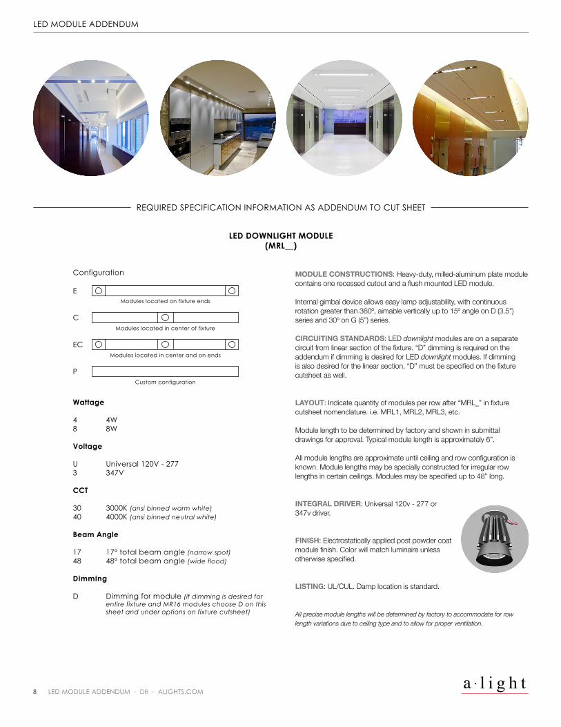
LED MODULE ADDENDUM
REQUIRED SPECIFICATION INFORMATION AS ADDENDUM TO CUT SHEET
Wattage
4 4W8 8W
Voltage
U Universal 120V - 2773 347V
CCT
30 3000K (ansi binned warm white)40 4000K (ansi binned neutral white)
Beam Angle
17 17º total beam angle (narrow spot)48 48º total beam angle (wide flood)
Dimming
D Dimming for module (if dimming is desired for entire fixture and MR16 modules choose D on this sheet and under options on fixture cutsheet)
LED DOWNLIGHT MODULE(MRL__)
Configuration
EModules located on fixture ends
Modules located in center of fixture
Modules located in center and on ends
Custom configuration
C
EC
P
MODULE CONSTRUCTIONS: Heavy-duty, milled-aluminum plate module contains one recessed cutout and a flush mounted LED module.
Internal gimbal device allows easy lamp adjustability, with continuous rotation greater than 360º, aimable vertically up to 15º angle on D (3.5”) series and 30º on G (5”) series.
CIRCUITING STANDARDS: LED downlight modules are on a separate circuit from linear section of the fixture. “D” dimming is required on the addendum if dimming is desired for LED downlight modules. If dimming is also desired for the linear section, “D” must be specified on the fixture cutsheet as well.
LAYOUT: Indicate quantity of modules per row after “MRL_” in fixture cutsheet nomenclature. i.e. MRL1, MRL2, MRL3, etc.
Module length to be determined by factory and shown in submittal drawings for approval. Typical module length is approximately 6”.
All module lengths are approximate until ceiling and row configuration is known. Module lengths may be specially constructed for irregular row lengths in certain ceilings. Modules may be specified up to 48” long.
INTEGRAL DRIVER: Universal 120v - 277 or 347v driver.
FINISH: Electrostatically applied post powder coat module finish. Color will match luminaire unless otherwise specified.
LISTING: UL/CUL. Damp location is standard.
All precise module lengths will be determined by factory to accommodate for row length variations due to ceiling type and to allow for proper ventilation.
l i g h t3728 MARITIME WAY, OCEANSIDE, CA 92056
760.727.7675 · ALIGHTS.COM/D6