lifts scissor lectric - tri-countytoolrental.com · operator's manual e lectric scissor lifts...
TRANSCRIPT
Operator's manual
ELE
CTR
IC S
CIS
SO
R L
IFTS
Operator's manualELECTRIC SCISSOR LIFTS
Compact 8 (Compact 2032E) - Compact 8W (Compact 2247E) - Compact 10 (Compact 2747E) - Compact 10N (Compact 2632E) - Compact 10N-1 -
Compact 12 (Compact 3347E) - Compact 14 (Compact 3947E) - Optimum 6 (Optimum 1530E) -
Optimum 8 (Optimum 1930E) - Optimum 8-1 - Compact 10RTE (Compact 2668RTE) - Compact 12RTE (Compact 3368RTE)
2420332270
e07.11
2420332270 e09.11 EN

Electric scissor lifts
EN
2 2420332270 e09.11 EN
CONT
ENTS
Operator's manual
CONTENTS
1 - Operator's manual . . . . . . . . . . . . . . . . . . . . . . . . . . . . . . . 7
2 - After Sales Service . . . . . . . . . . . . . . . . . . . . . . . . . . . . . . . 7
3 - Compliance . . . . . . . . . . . . . . . . . . . . . . . . . . . . . . . . . . . . . 8
4 - HAULOTTE Services® contact details. . . . . . . . . . . . . . . 9
ASAFETY PRECAUTIONS1 - Recommendations . . . . . . . . . . . . . . . . . . . . . . . . . . . . . . 11
1.1 - Operator's manual . . . . . . . . . . . . . . . . . . . . . . . . . . . . . . . . . . . . . . . . . . . . 11 1.2 - Symbols used . . . . . . . . . . . . . . . . . . . . . . . . . . . . . . . . . . . . . . . . . . . . . . . . 11 1.3 - Label colors . . . . . . . . . . . . . . . . . . . . . . . . . . . . . . . . . . . . . . . . . . . . . . . . . . 12
2 - Pre-operation instructions. . . . . . . . . . . . . . . . . . . . . . . . 13
2.1 - General instructions . . . . . . . . . . . . . . . . . . . . . . . . . . . . . . . . . . . . . . . . . . . 13 2.2 - Specific instructions. . . . . . . . . . . . . . . . . . . . . . . . . . . . . . . . . . . . . . . . . . . . 13
3 - Operation instructions . . . . . . . . . . . . . . . . . . . . . . . . . . . 14
3.1 - Prohibitions. . . . . . . . . . . . . . . . . . . . . . . . . . . . . . . . . . . . . . . . . . . . . . . . . . . 14 3.2 - Potential risks. . . . . . . . . . . . . . . . . . . . . . . . . . . . . . . . . . . . . . . . . . . . . . . . . 15 3.2.1 - Risk of command system disturbance . . . . . . . . . . . . . . . . . . . . 15 3.2.2 - Risk of falling . . . . . . . . . . . . . . . . . . . . . . . . . . . . . . . . . . . . . . . 15 3.2.3 - Risk of electrocution . . . . . . . . . . . . . . . . . . . . . . . . . . . . . . . . . . 16 3.2.4 - Risk of uncontrolled movement and overturning . . . . . . . . . . . . 16 3.2.5 - Risk of burns and explosion . . . . . . . . . . . . . . . . . . . . . . . . . . . . 18 3.2.6 - Risk of crushing and collision . . . . . . . . . . . . . . . . . . . . . . . . . . . 18
BINTERVENOR'S RESPONSIBILITY1 - Owner's (or hirer's) responsibility. . . . . . . . . . . . . . . . . . 19
2 - Employer's responsibility . . . . . . . . . . . . . . . . . . . . . . . . 19
3 - Trainer's responsibility . . . . . . . . . . . . . . . . . . . . . . . . . . 19
4 - Operator's responsibility . . . . . . . . . . . . . . . . . . . . . . . . . 19
5 - Inspection and maintenance . . . . . . . . . . . . . . . . . . . . . . 20
CMACHINE LAYOUT1 - Identification . . . . . . . . . . . . . . . . . . . . . . . . . . . . . . . . . . . 21
2 - Main components . . . . . . . . . . . . . . . . . . . . . . . . . . . . . . . 22
3 - Safety devices. . . . . . . . . . . . . . . . . . . . . . . . . . . . . . . . . . 24
3.1 - Sliding (or swinging) intermediate guardrail. . . . . . . . . . . . . . . . . . . . . . . 24 3.2 - Anchorage point (Please see machine configuration) . . . . . . . . . . . . . 25 3.3 - Maintenance support. . . . . . . . . . . . . . . . . . . . . . . . . . . . . . . . . . . . . . . . . . 26 3.4 - Folding guardrails - Option . . . . . . . . . . . . . . . . . . . . . . . . . . . . . . . . . . . . . 26
4 - Labels. . . . . . . . . . . . . . . . . . . . . . . . . . . . . . . . . . . . . . . . . 27
4.1 - Classification plan . . . . . . . . . . . . . . . . . . . . . . . . . . . . . . . . . . . . . . . . . . . . . 27 4.1.1 - Red labels. . . . . . . . . . . . . . . . . . . . . . . . . . . . . . . . . . . . . . . . . . 27 4.1.2 - Orange labels . . . . . . . . . . . . . . . . . . . . . . . . . . . . . . . . . . . . . . . 30 4.1.3 - Yellow labels. . . . . . . . . . . . . . . . . . . . . . . . . . . . . . . . . . . . . . . . 31 4.1.4 - Other labels . . . . . . . . . . . . . . . . . . . . . . . . . . . . . . . . . . . . . . . . 32 4.1.5 - Green labels . . . . . . . . . . . . . . . . . . . . . . . . . . . . . . . . . . . . . . . . 36 4.2 - Identification . . . . . . . . . . . . . . . . . . . . . . . . . . . . . . . . . . . . . . . . . . . . . . . . . . 36
5 - Control boxes . . . . . . . . . . . . . . . . . . . . . . . . . . . . . . . . . . 48
5.1 - Ground control box - Emergency control panel. . . . . . . . . . . . . . . . . . . 48 5.2 - Platform control box . . . . . . . . . . . . . . . . . . . . . . . . . . . . . . . . . . . . . . . . . . . 50
3
Operator's manual
DOPERATING PRINCIPLE1 - Description . . . . . . . . . . . . . . . . . . . . . . . . . . . . . . . . . . . . 55
2 - Safety devices. . . . . . . . . . . . . . . . . . . . . . . . . . . . . . . . . . 55
2.1 - Activation of controls . . . . . . . . . . . . . . . . . . . . . . . . . . . . . . . . . . . . . . . . . . . 55 2.2 - Drive speed. . . . . . . . . . . . . . . . . . . . . . . . . . . . . . . . . . . . . . . . . . . . . . . . . . . 55 2.3 - Steering . . . . . . . . . . . . . . . . . . . . . . . . . . . . . . . . . . . . . . . . . . . . . . . . . . . . . . 56 2.4 - Load limiting in the platform (if fitted) . . . . . . . . . . . . . . . . . . . . . . . . . . . . . 56 2.5 - Anti-pothole safety system. . . . . . . . . . . . . . . . . . . . . . . . . . . . . . . . . . . . . . 56 2.6 - Battery discharge indicator-Hour meter . . . . . . . . . . . . . . . . . . . . . . . . . . 57 2.6.1 - Hour meter . . . . . . . . . . . . . . . . . . . . . . . . . . . . . . . . . . . . . . . . . 57 2.6.2 - Automatic reset . . . . . . . . . . . . . . . . . . . . . . . . . . . . . . . . . . . . . 57 2.7 - On-board charger . . . . . . . . . . . . . . . . . . . . . . . . . . . . . . . . . . . . . . . . . . . . . 58 2.8 - manual extension . . . . . . . . . . . . . . . . . . . . . . . . . . . . . . . . . . . . . . . . . . . . . 58
EDRIVING1 - Recommendations . . . . . . . . . . . . . . . . . . . . . . . . . . . . . . 59
2 - Checks before use . . . . . . . . . . . . . . . . . . . . . . . . . . . . . . 59
2.1 - Visual inspections . . . . . . . . . . . . . . . . . . . . . . . . . . . . . . . . . . . . . . . . . . . . . 59 2.1.1 - General mechanical functions . . . . . . . . . . . . . . . . . . . . . . . . . . 59 2.1.2 - Environment . . . . . . . . . . . . . . . . . . . . . . . . . . . . . . . . . . . . . . . . 61 2.2 - Functional tests . . . . . . . . . . . . . . . . . . . . . . . . . . . . . . . . . . . . . . . . . . . . . . . 61 2.2.1 - Safety features . . . . . . . . . . . . . . . . . . . . . . . . . . . . . . . . . . . . . . 61 2.2.2 - Ground control box controls (emergency station) . . . . . . . . . . . 62 2.2.3 - Platform control box controls (driving station) . . . . . . . . . . . . . . 62 2.3 - Periodical checks. . . . . . . . . . . . . . . . . . . . . . . . . . . . . . . . . . . . . . . . . . . . . . 62 2.4 - Repairs and adjustments. . . . . . . . . . . . . . . . . . . . . . . . . . . . . . . . . . . . . . . 62 2.5 - Inspection / Testing requirements . . . . . . . . . . . . . . . . . . . . . . . . . . . . . . . 63
3 - Operation. . . . . . . . . . . . . . . . . . . . . . . . . . . . . . . . . . . . . . 63
3.1 - Test procedure. . . . . . . . . . . . . . . . . . . . . . . . . . . . . . . . . . . . . . . . . . . . . . . . 63 3.1.1 - Emergency stop switch- button function (cut out)
. . . . . . . . . . . . . . . . . . . . . . . . . . . . . . . . . . . . . . . . . . . . . . . . . . 63 3.1.2 - Tilt sensor switch operation . . . . . . . . . . . . . . . . . . . . . . . . . . . . 64 3.1.3 - Visual and sound alarms . . . . . . . . . . . . . . . . . . . . . . . . . . . . . . 65 3.1.4 - Weighing system . . . . . . . . . . . . . . . . . . . . . . . . . . . . . . . . . . . . 65 3.1.5 - 8 m(26 ft3 in) drive cut-off (Floor height) . . . . . . . . . . . . . . . . . . 65 3.2 - Operation from ground position . . . . . . . . . . . . . . . . . . . . . . . . . . . . . . . . . 65 3.2.1 - Machine start-up. . . . . . . . . . . . . . . . . . . . . . . . . . . . . . . . . . . . . 65 3.2.2 - Machine shutdown . . . . . . . . . . . . . . . . . . . . . . . . . . . . . . . . . . . 66 3.2.3 - Movement control. . . . . . . . . . . . . . . . . . . . . . . . . . . . . . . . . . . . 66 3.2.4 - Other controls. . . . . . . . . . . . . . . . . . . . . . . . . . . . . . . . . . . . . . . 66 3.3 - Operations from the platform . . . . . . . . . . . . . . . . . . . . . . . . . . . . . . . . . . . 66 3.3.1 - Machine start-up. . . . . . . . . . . . . . . . . . . . . . . . . . . . . . . . . . . . . 66 3.3.2 - Machine shutdown . . . . . . . . . . . . . . . . . . . . . . . . . . . . . . . . . . . 66 3.3.3 - Movement control. . . . . . . . . . . . . . . . . . . . . . . . . . . . . . . . . . . . 67 3.3.4 - Other controls. . . . . . . . . . . . . . . . . . . . . . . . . . . . . . . . . . . . . . . 69
4
CONT
ENTS
Operator's manual
FSPECIAL PROCEDURE1 - Emergency lowering. . . . . . . . . . . . . . . . . . . . . . . . . . . . . 71
1.1 - Principle. . . . . . . . . . . . . . . . . . . . . . . . . . . . . . . . . . . . . . . . . . . . . . . . . . . . . . 71 1.2 - Procedure. . . . . . . . . . . . . . . . . . . . . . . . . . . . . . . . . . . . . . . . . . . . . . . . . . . . 71
2 - Towing . . . . . . . . . . . . . . . . . . . . . . . . . . . . . . . . . . . . . . . . 71
2.1 - Brake release. . . . . . . . . . . . . . . . . . . . . . . . . . . . . . . . . . . . . . . . . . . . . . . . . 71
3 - Loading and unloading . . . . . . . . . . . . . . . . . . . . . . . . . . 72
3.1 - Principle. . . . . . . . . . . . . . . . . . . . . . . . . . . . . . . . . . . . . . . . . . . . . . . . . . . . . . 72 3.1.1 - Loading by ramp. . . . . . . . . . . . . . . . . . . . . . . . . . . . . . . . . . . . . 72 3.1.2 - Unloading by ramps . . . . . . . . . . . . . . . . . . . . . . . . . . . . . . . . . . 72 3.1.3 - Loading by lifting. . . . . . . . . . . . . . . . . . . . . . . . . . . . . . . . . . . . . 73 3.2 - Putting in transport position. . . . . . . . . . . . . . . . . . . . . . . . . . . . . . . . . . . . . 73 3.3 - Unloading . . . . . . . . . . . . . . . . . . . . . . . . . . . . . . . . . . . . . . . . . . . . . . . . . . . . 75 3.4 - Warning. . . . . . . . . . . . . . . . . . . . . . . . . . . . . . . . . . . . . . . . . . . . . . . . . . . . . . 75
GTECHNICAL CHARACTERISTICS1 - Main characteristics . . . . . . . . . . . . . . . . . . . . . . . . . . . . . 77
2 - Overall dimensions. . . . . . . . . . . . . . . . . . . . . . . . . . . . . 101
3 - Working area . . . . . . . . . . . . . . . . . . . . . . . . . . . . . . . . . . 104
3.1 - MachineC8 . . . . . . . . . . . . . . . . . . . . . . . . . . . . . . . . . . . . . . . . . . . . . . . . . 104 3.2 - MachineC8W . . . . . . . . . . . . . . . . . . . . . . . . . . . . . . . . . . . . . . . . . . . . . . 105 3.3 - MachineC10N . . . . . . . . . . . . . . . . . . . . . . . . . . . . . . . . . . . . . . . . . . . . . . 106 3.4 - MachineC10 . . . . . . . . . . . . . . . . . . . . . . . . . . . . . . . . . . . . . . . . . . . . . . . 107 3.5 - MachineC12 . . . . . . . . . . . . . . . . . . . . . . . . . . . . . . . . . . . . . . . . . . . . . . . 108 3.6 - MachineC14 . . . . . . . . . . . . . . . . . . . . . . . . . . . . . . . . . . . . . . . . . . . . . . . 109 3.7 - MachineOPTIMUM 6 . . . . . . . . . . . . . . . . . . . . . . . . . . . . . . . . . . . . . . . 110 3.8 - MachineOPTIMUM 8 . . . . . . . . . . . . . . . . . . . . . . . . . . . . . . . . . . . . . . . 111 3.9 - MachineCOMPACT 10RTE . . . . . . . . . . . . . . . . . . . . . . . . . . . . . . . . . 112 3.10 - MachineCOMPACT 12RTE . . . . . . . . . . . . . . . . . . . . . . . . . . . . . . . . . 113
4 - AS - CE standard specificities . . . . . . . . . . . . . . . . . . . 114
4.1 - Overload test . . . . . . . . . . . . . . . . . . . . . . . . . . . . . . . . . . . . . . . . . . . . . . . . 114 4.2 - Functional test . . . . . . . . . . . . . . . . . . . . . . . . . . . . . . . . . . . . . . . . . . . . . . . 114 4.3 - Stability test. . . . . . . . . . . . . . . . . . . . . . . . . . . . . . . . . . . . . . . . . . . . . . . . . . 115
5 - Declaration of conformity . . . . . . . . . . . . . . . . . . . . . . . 125
HINTERVENTION REGISTER1 - Intervention register . . . . . . . . . . . . . . . . . . . . . . . . . . . . 127
5
Operator's manual
6
Electric scissor lifts
You have just purchased a HAULOTTE® product
and we would like to thank you for your business.
1 - Operator's manual
As stated on the delivery slip, this manual is one of the documents in the on-board document holderprovided upon delivery of your HAULOTTE® machine.
The operator manual is a translation of the original instructions.
Safe operation of this product can only be assured if you follow the operating instructions contained inthis manual.
We would particularly like to draw your attention to 2 essential points :
• Compliance with safety instruction (machine, use, environment)
• Use of the equipment within the performance limits.
2 - After Sales Service
Our HAULOTTE Services® After Sales Service is at your disposal throughout your machine's servicelife to ensure optimal use of your HAULOTTE product..
• When contacting our After Sales Service, ensure that you provide the machine model and serialnumber.
• When ordering any consumables or spare parts, please use this manual and the Haulotte Essentialcatalogue to receive your genuine HAULOTTE spare parts, your only guarantee of partsinterchangeability and correct machine operation..
• If there is an equipment malfunction involving a HAULOTTE® product, then contact HAULOTTEServices® immediately even if the malfunction does not involve material and/or bodily damage..
• HAULOTTE® must be informed in the event of an incident that either involves one of these productsor has caused bodily injury or significant deterioration of property (personal property or the product);contact HAULOTTE Services® immediately (See : HAULOTTE Services® contact details)
With regard to the designation of our equipment, we stress that this is purely for commercial purposes andnot to be confused with the technical characteristics. Only the tables of technical characteristics shouldbe used to study the suitability of the equipment for the intended use.
72420332270 e09.11 EN
Electric scissor lifts
3 - Compliance
We would like to remind you that HAULOTTE® complies with the provisions of any applicabledirectives applicable to this type of machine.
HAULOTTE advises you that NO modifications carried out without the written permissionof HAULOTTE® will void the HAULOTTE warranty..
HAULOTTE® cannot be held liable for any changes to the technical specifications contained in thismanual.
HAULOTTE® reserves the right to alter technical specifications and to make improvements ormodifications to the machine without modifying this manual.
Certain options can modify the machine's operating characteristics and its associated safety. If yourmachine was originally delivered with options fitted, replacing a safety component associated with aparticular options not require any particular precautions other than those associated with the installationitself (static test).
Otherwise, it is essential to follow the manufacturer's recommendations below : • Installation by authorised HAULOTTE® personnel only.
• Update the manufacturer's identification plate.
• Have stability tests carried out by a certified agency/competent person.
• Ensure label compliance.
8 2420332270 e09.11 EN

Electric scissor lifts
4 - HAULOTTE Services® contact detailsHAULOTTE Services® contact details
HAULOTTE FRANCE PARC DES LUMIERES
601 RUE NICEPHORE NIEPCE69800 SAINT-PRIEST
TECHNICAL Department: +33 (0)820 200 089
SPARE PARTS : +33 (0)820 205 344
FAX : +33 (0)4 72 88 01 43 E-mail : [email protected]
www.haulotte.fr
HAULOTTE ITALIA
VIA LOMBARDIA 15 20098 SAN GIULIANO MILANESE
(MI) TEL: +39 02 98 97 01 FAX: +39 02 9897 01 25
E-mail : [email protected]
www.haulotte.it
HAULOTTE HUBARBEITSBÜHNEN GmbH
AN DER MÖHLINHALLE 1 D-79189 BAD KROZINGEN-HAUSEN
TEL : +49 (0) 7633 806 92-0 FAX : +49 (0) 7633 806 92-18
E.mail : [email protected] www.haulotte.de
HAULOTTE VOSTOK, OOO 3, ZHUKOVSKOGO STREET
DOLGOPRUDNY 141700 MOSCOW REGION
RUSSIAN FEDERATION TEL/FAX : +7 495 579 57 17
E.mail : [email protected] www.haulotte-international.com
HAULOTTE DO BRASIL AV. CECI, 608 – B 13
CEP: 06460-120 – TAMBORE BARUERI – SAO PAULO – BRASIL
TEL : +55 11 4208 4206 FAX : +55 11 4191 4677
E.mail : [email protected] www.haulotte.com.br
HAULOTTE IBERICA
C/ARGENTINA N° 13 - P.I. LA GARENA 28806 ALCALA DE HENARES
MADRID TEL : +34 902 886 455
TEL SAT : +34 902 886 444 FAX : +34 91 656 97 81
E.mail : [email protected] www.haulotte.es
HAULOTTE POLSKA Sp. Z.o.o.
UL. GRANICZNA 22 05-090 RASZYN - JANKI-
TEL : +48 22 720 08 80 FAX : +48 22 720 35 06
E-mail : [email protected]
www.haulotte.pl
HAULOTTE MÉXICO, Sa de Cv Calle 9 Este, Lote 18, Civac, Jiutepec,
Morelos CP 62500 Cuernavaca
México TEL : +52 77 7321 7923 FAX : +52 77 7516 8234
E-mail : [email protected]
www.haulotte-international.com
HAULOTTE PORTUGAL
ESTRADA NACIONAL NUM. 10 KM. 140 - LETRA K
2695 - 066 BOBADELA LRS TEL : + 351 21 995 98 10 FAX : + 351 21 995 98 19
E.mail : [email protected]
www.haulotte.es
HAULOTTE SINGAPORE Pte Ltd.
No.26 CHANGI NORTH WAY, SINGAPORE 498812
Parts and service Hotline: +65 6546 6179
FAX : +65 6536 3969 E-mail: [email protected]
www.haulotte.sg
HAULOTTE MIDDLE EAST FZE
PO BOX 293881 Dubaï Airport Free Zone
DUBAÏ United Arab Emirates
TEL : +971 (0)4 299 77 35 FAX : +971 (0) 4 299 60 28
E-mail : [email protected]
www.haulotte-international.com
HAULOTTE SCANDINAVIA AB Taljegårdsgatan 12
431 53 Mölndal SWEDEN
TEL : +46 31 744 32 90 FAX : +46 31 744 32 99
E-mail : [email protected] [email protected]
www.haulotte.se
HAULOTTE TRADING (SHANGHAI)
Co. Ltd. #7 WORKSHOP No 191 HUA
JIN ROADMIN HANG DISTRICT
SHANGHAI CHINA 201108
TEL : +86 21 6442 6610 FAX : +86 21 6442 6619
E-mail : [email protected]
www.haulotte.cn
HAULOTTE ARGENTINA Ruta Panamericana Km. 34,300 (Ramal A
Escobar) 1615 Gran Bourg (Provincia de Buenos
Aires) Argentina
TEL.: +54 033 27 45 21 91 FAX. +54 033 27 45 72 19
E-mail : [email protected]
www.haulotte-international.com
HAULOTTE UK Ltd STAFFORD PARK 6
TELFORD - SHROPSHIRE TF3 3AT TEL : +44 (0)1952 292753 FAX : + 44 (0)1952 292758
E.mail : [email protected] www.haulotte.co.uk
HAULOTTE GROUP / BILJAX125 TAYLOR PARKWAY
ARCHBOLD, OH 43502 – USA
TEL : +1 419 445 8915 FAX :+1 419 445 0367
Toll free : +1 800 537 0540
E.mail : [email protected]
www.haulotte-usa.com
HAULOTTE DO BRASIL AV. CECI, 608 – B 13
CEP: 06460-120 – TAMBORE BARUERI – SAO PAULO – BRASIL
TEL : +55 11 4688 1295 / +55 11 4208 4206
FAX : +55 11 4191 4677 E.mail : [email protected]
www.haulotte-international.com HAULOTTE NETHERLANDS BV
Koopvaardijweg 26 4906 CV OOSTERHOUT - Nederland
TEL : +31 (0) 162 670 707 FAX : +31 (0) 162 670 710 E.mail : [email protected]
HAULOTTE AUSTRALIA PTY Ltd46 GREENS ROAD
DANDENONG – VIC – 3175
TEL : +61 (0)3 9792 1000 FAX : +61 (0)3 9792 1011
E.mail : [email protected] h l
92420332270 e09.11 EN

Electric scissor lifts
10 2420332270 e09.11 EN
A
B
C
D
E
F
G
H
I
Electric scissor lifts
A- Safety precautions
Safety precautions1 - Recommendations
1.1 - OPERATOR'S MANUAL
This operators manual is specific to the HAULOTTE® products listed on the cover page of thismanual..
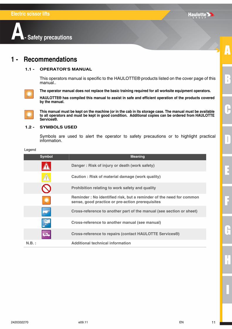
1.2 - SYMBOLS USED
Symbols are used to alert the operator to safety precautions or to highlight practicalinformation.
Legend
The operator manual does not replace the basic training required for all worksite equipment operators.
HAULOTTE® has compiled this manual to assist in safe and efficient operation of the products coveredby the manual.
This manual must be kept on the machine (or in the cab in its storage case. The manual must be availableto all operators and must be kept in good condition. Additional copies can be ordered from HAULOTTEServices®.
Symbol Meaning
Danger : Risk of injury or death (work safety)
Caution : Risk of material damage (work quality)
Prohibition relating to work safety and quality
Reminder : No identified risk, but a reminder of the need for common sense, good practice or pre-action prerequisites
Cross-reference to another part of the manual (see section or sheet)
Cross-reference to another manual (see manual)
Cross-reference to repairs (contact HAULOTTE Services®)
N.B. : Additional technical information
112420332270 e09.11 EN
Electric scissor lifts
A- Safety precautions
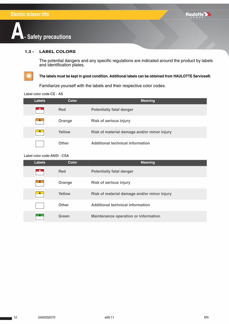
1.3 - LABEL COLORS
The potential dangers and any specific regulations are indicated around the product by labelsand identification plates.
Familiarize yourself with the labels and their respective color codes.
Label color code-CE - AS
Label color code-ANSI - CSA
The labels must be kept in good condition. Additional labels can be obtained from HAULOTTE Services®.
Labels Color Meaning
Red Potentially fatal danger
Orange Risk of serious injury
Yellow Risk of material damage and/or minor injury
Other Additional technical information
Labels Color Meaning
Red Potentially fatal danger
Orange Risk of serious injury
Yellow Risk of material damage and/or minor injury
Other Additional technical information
Green Maintenance operation or information
12 2420332270 e09.11 EN
A
B
C
D
E
F
G
H
I
Electric scissor lifts
A- Safety precautions
2 - Pre-operation instructions 2.1 - GENERAL INSTRUCTIONS
• On soft, unstable or cluttered ground.
• With wind blowing faster than the permissible limit. Check the maximum value in the technicalcharacteristics ( Section G 1-Main characteristics). Consult the Beaufort scale( Section A 3.2.4-Risk of uncontrolled movement and overturning).
• Close to power lines. Respect the safety distance ( Section A 3.2.3-Risk of electrocution).
• At ambient temperatures higher than 45 °C(113 °F) and lower than -15 °C(5 °F) .Consult HAULOTTE® if it is necessary to work outside this range.
• In an explosive atmosphere.
• During storms (risk of lightning).
• In the presence of strong electromagnetic fields (radar, etc ...).
N.B.-:-You are advised to use the machine under "NORMAL" climatic conditions.. If you need to usethe machine in climatic conditions likely to cause deterioration (humidity, temperatures outside therecommended ranges, salinity, corrosiveness, atmospheric pressure), contact HAULOTTE Services®.Reduce intervals between servicing.
N.B.-:-Whilst the machine is not in use, care must be taken to ensure that if the machine is not lockedin a secure location, that the unit key switch is removed to prevent unauthorised use of the machine.
2.2 - SPECIFIC INSTRUCTIONS
• If the load in the platform exceeds the maximum load authorized. Check the maximum value in thetechnical characteristics ( Section G 1-Main characteristics).
• If the ground slope is greater than the permissible limit. Check the maximum value in the technicalcharacteristics ( Section G 1-Main characteristics).
• At night unless the machine is equipped with the optional light.
• If the number of persons exceeds the permissible limit. Check the maximum value in the technicalcharacteristics ( Section G 1-Main characteristics)
• If the side force is greater than the permissible force. Check the maximum value in the technicalcharacteristics ( Section G 1-Main characteristics)
• The employer has the obligation to issue a driving permit to the operator.
• The employer is obliged to inform the operator of the local regulations.
Do not operate the product in the following situations :
Do not operate the product in the following situations :
132420332270 e09.11 EN
Electric scissor lifts
A- Safety precautions
3 - Operation instructions
3.1 - PROHIBITIONS
It is preferable to operate the machine on flat, consolidated ground (tarmac, concrete, etc.).
• Never use a faulty machine (hydraulic leaks, worn tires, malfunction).
• Never operate the machine controls suddenly.
• Never place the machine against a structure to hold that structure in place.
• Never use the machine to tow other machines or to drag materials.
• Never expose the batteries or electrical components to water (pressure cleaner, rain).
• Never disable the safety devices.
• Do not make contact with a fixed or mobile obstacle. The contact can cause premature deterioration ofthe structure and lead to the corruption of certain safety elements.
• Do not climb onto the covers.
• Never use the machine with only an operator in the platform. It must be used by 2 operators.
• Never use the machine when the platform is cluttered.
• Never increase the surface area of the platform by using floor extensions or accessories not authorizedby HAULOTTE®.
• Never leave the hydraulic cylinders fully extended or retracted before switching off the machine, orduring an extended stop period.
• Never use the machine with material or objects suspended from the guard-rail.
• Never use the machine with elements that can increase the wind force (panels).
• Never increase the working height by using attachments (ladder).
• Never use the guardrail as a means of access for climbing in or out of the platform. The basket can beeasily accessed in its low position. For machines fitted with : Steps have been provided for this purposewhere required.
• Never climb on the guardrail.
• Do not use the machine if the guard rails are not correctly installed and locked.
• Never use the machine without fitting the sliding (or rotating) middle rail, closing the safety gate or theswing gates beforehand.
• Never use the machine as a crane, material lift or elevator.
• Never use the machine for any other purpose than to transport people, their tools and material to thedesired place.
• Never drive fast in narrow or cluttered areas. Keep speed under control in bends.
• Never tow the machine over extended distances (it must be transported on a trailer).
14 2420332270 e09.11 EN
A
B
C
D
E
F
G
H
I
Electric scissor lifts
A- Safety precautions
3.2 - POTENTIAL RISKS
3.2.1 - Risk of command system disturbance
Risk of disrupted movement. Maintain clearance from high voltage lines or magnetic fields.
3.2.2 - Risk of falling
When in the platform, respect the following instructions :
• Carry individual protection equipment adapted to the work conditions and localrules.
• Avoid contact with fixed or mobile obstacles (other machines).
• Ensure that the adjustable midrail is closed (low position and against the guardrails).
• Ensure that the gate is closed and locked (For machines fitted with).
• Hold on securely to the guardrails during elevation and driving.
• Do not sit, stand, or climb on the platform guard rails.
• Ensure that guard rails are correctly installed and locked.
• Always keep your feet firmly on the floor of the platform.
• Remove any trace of oil or grease from the steps, floor, handrail and the guardrails.
• Keep the floor of the platform free of debris.
• Do not leave the platform until it is fully in its stowed position.
• Do not climb on to the platform if the machine is not in the stowed position.
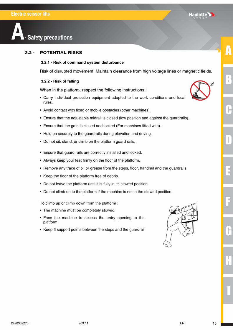
To climb up or climb down from the platform :
• The machine must be completely stowed.
• Face the machine to access the entry opening to theplatform
• Keep 3 support points between the steps and the guardrail
152420332270 e09.11 EN
Electric scissor lifts
A- Safety precautions
3.2.3 - Risk of electrocution
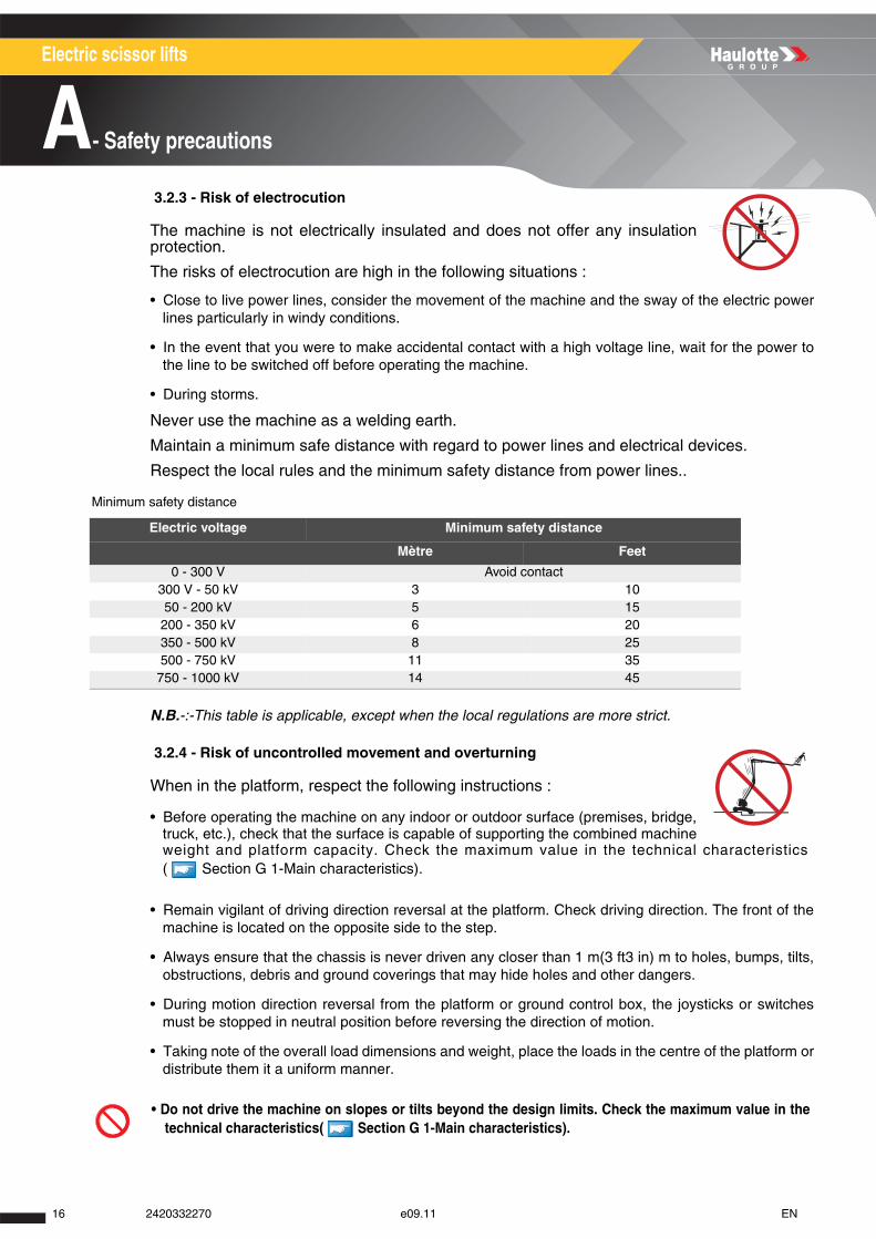
The machine is not electrically insulated and does not offer any insulationprotection.
The risks of electrocution are high in the following situations :
• Close to live power lines, consider the movement of the machine and the sway of the electric powerlines particularly in windy conditions.
• In the event that you were to make accidental contact with a high voltage line, wait for the power tothe line to be switched off before operating the machine.
• During storms.
Never use the machine as a welding earth.
Maintain a minimum safe distance with regard to power lines and electrical devices.
Respect the local rules and the minimum safety distance from power lines..
Minimum safety distance
N.B.-:-This table is applicable, except when the local regulations are more strict.
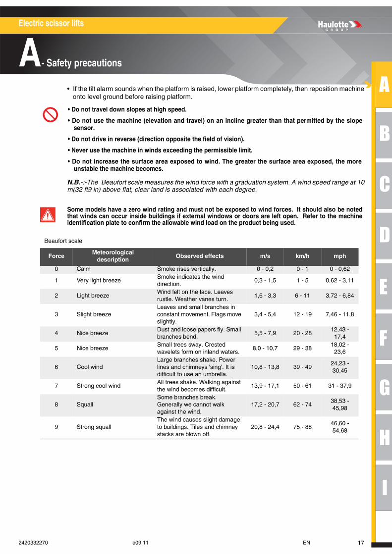
3.2.4 - Risk of uncontrolled movement and overturning
When in the platform, respect the following instructions :
• Before operating the machine on any indoor or outdoor surface (premises, bridge,truck, etc.), check that the surface is capable of supporting the combined machineweight and platform capacity. Check the maximum value in the technical characteristics( Section G 1-Main characteristics).
• Remain vigilant of driving direction reversal at the platform. Check driving direction. The front of themachine is located on the opposite side to the step.
• Always ensure that the chassis is never driven any closer than 1 m(3 ft3 in) m to holes, bumps, tilts,obstructions, debris and ground coverings that may hide holes and other dangers.
• During motion direction reversal from the platform or ground control box, the joysticks or switchesmust be stopped in neutral position before reversing the direction of motion.
• Taking note of the overall load dimensions and weight, place the loads in the centre of the platform ordistribute them it a uniform manner.
Electric voltage Minimum safety distance
Mètre Feet
0 - 300 V Avoid contact300 V - 50 kV 3 1050 - 200 kV 5 15
200 - 350 kV 6 20350 - 500 kV 8 25500 - 750 kV 11 35
750 - 1000 kV 14 45
• Do not drive the machine on slopes or tilts beyond the design limits. Check the maximum value in thetechnical characteristics( Section G 1-Main characteristics).
16 2420332270 e09.11 EN
A
B
C
D
E
F
G
H
I
Electric scissor lifts
A- Safety precautions
• If the tilt alarm sounds when the platform is raised, lower platform completely, then reposition machineonto level ground before raising platform.
N.B.-:-The Beaufort scale measures the wind force with a graduation system. A wind speed range at 10m(32 ft9 in) above flat, clear land is associated with each degree.
Beaufort scale
• Do not travel down slopes at high speed.
• Do not use the machine (elevation and travel) on an incline greater than that permitted by the slopesensor.
• Do not drive in reverse (direction opposite the field of vision).
• Never use the machine in winds exceeding the permissible limit.
• Do not increase the surface area exposed to wind. The greater the surface area exposed, the moreunstable the machine becomes.
Some models have a zero wind rating and must not be exposed to wind forces. It should also be notedthat winds can occur inside buildings if external windows or doors are left open. Refer to the machineidentification plate to confirm the allowable wind load on the product being used.
ForceMeteorological
descriptionObserved effects m/s km/h mph
0 Calm Smoke rises vertically. 0 - 0,2 0 - 1 0 - 0,62
1 Very light breezeSmoke indicates the wind direction.
0,3 - 1,5 1 - 5 0,62 - 3,11
2 Light breezeWind felt on the face. Leaves rustle. Weather vanes turn.
1,6 - 3,3 6 - 11 3,72 - 6,84
3 Slight breezeLeaves and small branches in constant movement. Flags move slightly.
3,4 - 5,4 12 - 19 7,46 - 11,8
4 Nice breezeDust and loose papers fly. Small branches bend.
5,5 - 7,9 20 - 2812,43 -
17,4
5 Nice breezeSmall trees sway. Crested wavelets form on inland waters.
8,0 - 10,7 29 - 3818,02 -
23,6
6 Cool windLarge branches shake. Power lines and chimneys 'sing'. It is difficult to use an umbrella.
10,8 - 13,8 39 - 4924,23 - 30,45
7 Strong cool windAll trees shake. Walking against the wind becomes difficult.
13,9 - 17,1 50 - 61 31 - 37,9
8 SquallSome branches break. Generally we cannot walk against the wind.
17,2 - 20,7 62 - 7438,53 - 45,98
9 Strong squallThe wind causes slight damage to buildings. Tiles and chimney stacks are blown off.
20,8 - 24,4 75 - 8846,60 - 54,68
172420332270 e09.11 EN
Electric scissor lifts
A- Safety precautions
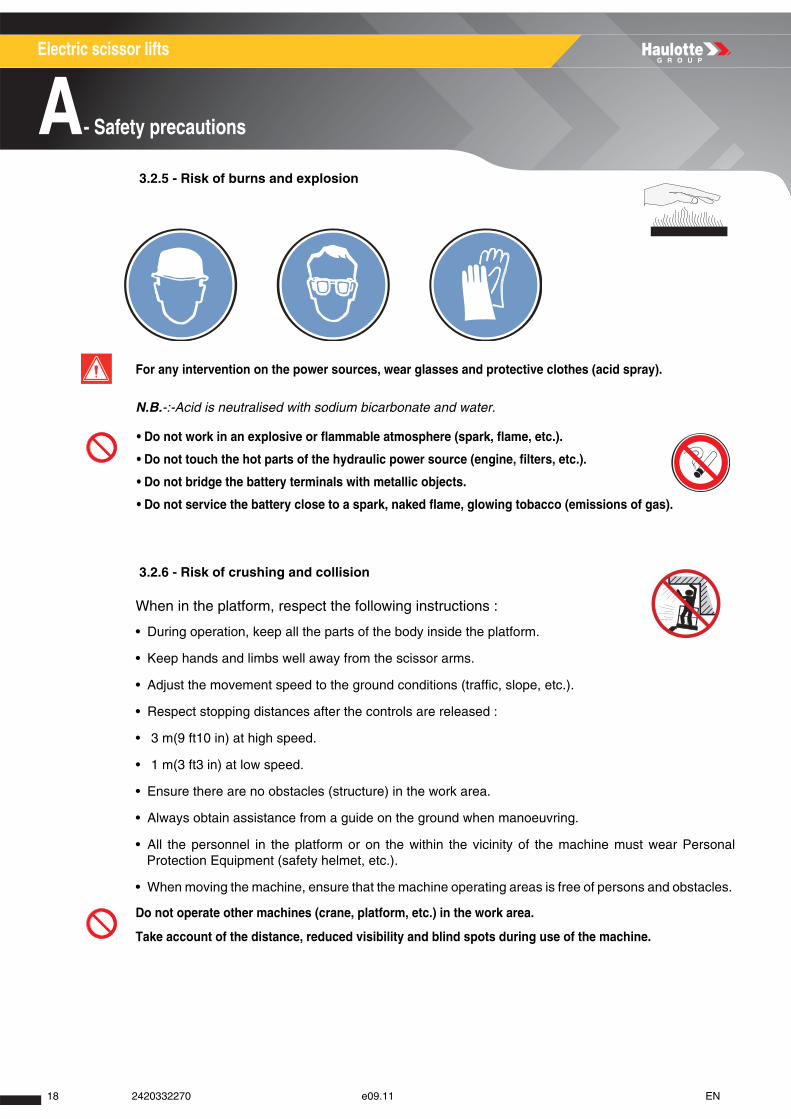
3.2.5 - Risk of burns and explosion
N.B.-:-Acid is neutralised with sodium bicarbonate and water.
3.2.6 - Risk of crushing and collision
When in the platform, respect the following instructions :
• During operation, keep all the parts of the body inside the platform.
• Keep hands and limbs well away from the scissor arms.
• Adjust the movement speed to the ground conditions (traffic, slope, etc.).
• Respect stopping distances after the controls are released :
• 3 m(9 ft10 in) at high speed.
• 1 m(3 ft3 in) at low speed.
• Ensure there are no obstacles (structure) in the work area.
• Always obtain assistance from a guide on the ground when manoeuvring.
• All the personnel in the platform or on the within the vicinity of the machine must wear PersonalProtection Equipment (safety helmet, etc.).
• When moving the machine, ensure that the machine operating areas is free of persons and obstacles.
For any intervention on the power sources, wear glasses and protective clothes (acid spray).
• Do not work in an explosive or flammable atmosphere (spark, flame, etc.).
• Do not touch the hot parts of the hydraulic power source (engine, filters, etc.).
• Do not bridge the battery terminals with metallic objects.
• Do not service the battery close to a spark, naked flame, glowing tobacco (emissions of gas).
Do not operate other machines (crane, platform, etc.) in the work area.
Take account of the distance, reduced visibility and blind spots during use of the machine.
18 2420332270 e09.11 EN
A
B
C
D
E
F
G
H
I
Electric scissor lifts
B- Intervenor's responsibility
Intervenor's responsibility1 - Owner's (or hirer's) responsibility
The owner (or hirer) has the obligation to inform operators of the instructions contained in the OperatorManual.
The owner (or hirer) has the obligation to renew all manuals or labels that are either missing or in badcondition. Additional copies can be ordered from HAULOTTE Services®.
The owner (or hirer) is responsible for applying the local regulations regarding operation of themachine.
2 - Employer's responsibility
. The employer has the obligation to issue a driving permit to the operator.
N.B.-:-In accordance with the regulation in the country where the machine is operating, the user mustbe authorized to drive by the doctor of Labour Ministry.
3 - Trainer's responsibility
The trainer must be qualified to provide training to operators in accordance with applicable localregulations. The training must be given in an obstacle-free area until the trainee is consideredcompetent as defined by the training program undertaken.
4 - Operator's responsibility
The operator must read and understand the contents of this manual and the labels affixed on themachine.
The operator must inform the owner (or hirer) if the manual or any labels are missing or in poorcondition, and of any malfunction of the machine.
The operator may only operate the machine for the purpose intended by the manufacturer.
All operators must become familiar with and fully understand the emergency controls and how tooperate the machine in an emergency as a component of their formal operator training.
The operator has the obligation stop using the machine in the event of malfunction or safety problemson the machine or in the work area and report the problem to his/her supervisor.
Forbid anyone from operating the machine who is : • Under the influence of drugs, alcohol, etc..
• subject to fits, loss of motor skills, dizziness, etc..
Only authorized and qualified operators may operate HAULOTTE® machines.
192420332270 e09.11 EN
Electric scissor lifts
B- Intervenor's responsibility
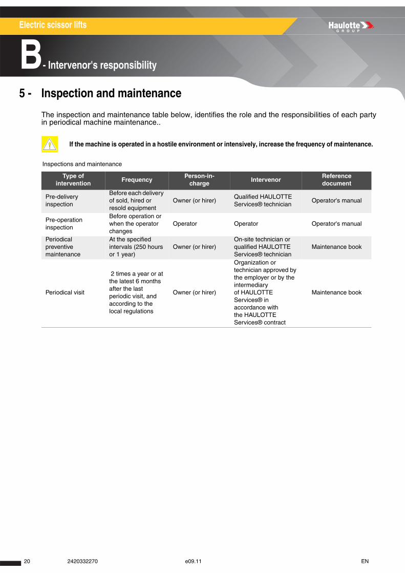
5 - Inspection and maintenance
The inspection and maintenance table below, identifies the role and the responsibilities of each partyin periodical machine maintenance..
Inspections and maintenance
If the machine is operated in a hostile environment or intensively, increase the frequency of maintenance.
Type of intervention
FrequencyPerson-in-
chargeIntervenor
Reference document
Pre-delivery inspection
Before each delivery of sold, hired or resold equipment
Owner (or hirer)Qualified HAULOTTE Services® technician
Operator's manual
Pre-operation inspection
Before operation or when the operator changes
Operator Operator Operator's manual
Periodical preventive maintenance
At the specified intervals (250 hours or 1 year)
Owner (or hirer)On-site technician or qualified HAULOTTE Services® technician
Maintenance book
Periodical visit
2 times a year or at the latest 6 months after the last periodic visit, and according to the local regulations
Owner (or hirer)
Organization or technician approved by the employer or by the intermediary of HAULOTTE Services® in accordance with the HAULOTTE Services® contract
Maintenance book
20 2420332270 e09.11 EN
A
B
C
D
E
F
G
H
I
Electric scissor lifts
C- Machine layout
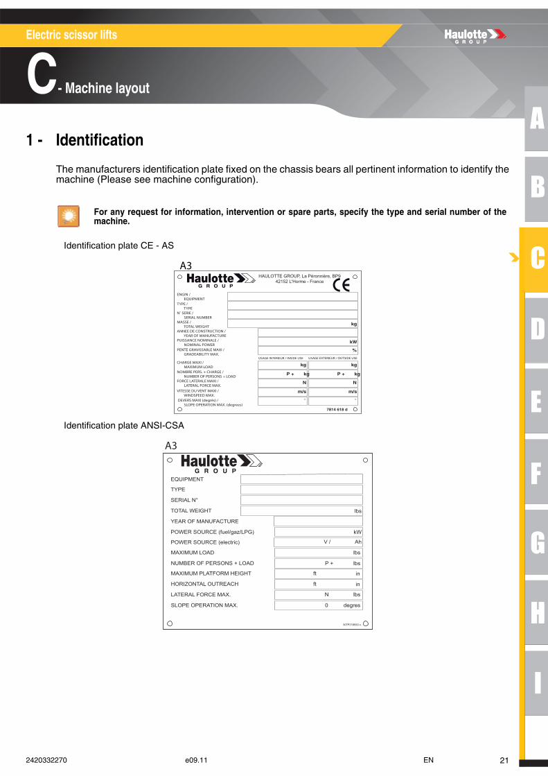
Machine layout1 - Identification
The manufacturers identification plate fixed on the chassis bears all pertinent information to identify themachine (Please see machine configuration).
Identification plate CE - AS
Identification plate ANSI-CSA
For any request for information, intervention or spare parts, specify the type and serial number of themachine.
ENGIN / EQUIPMENTTYPE / TYPEN˚ SERIE / SERIAL NUMBERMASSE / TOTAL WEIGHTANNEE DE CONSTRUCTION / YEAR OF MANUFACTUREPUISSANCE NOMINALE / NOMINAL POWER
kg
kW
PENTE GRAVISSABLE MAXI / GRADEABILITY MAX.
%
7814 618 d
CHARGE MAXI / MAXIMUM LOADNOMBRE PERS. + CHARGE / NUMBER OF PERSONS + LOADFORCE LATERALE MAXI / LATERAL FORCE MAX.VITESSE DU VENT MAXI / WINDSPEED MAX. DEVERS MAXI (degrés) / SLOPE OPERATION MAX. (degrees)
USAGE INTERIEUR / INSIDE USE USAGE EXTERIEUR / OUTSIDE USE
kg
P + kg
N
m/s
˚
kg
P + kg
N
m/s
˚
HAULOTTE GROUP, La Péronnière, BP942152 L'Horme - France
A3
EQUIPMENT
TYPE
SERIAL N°
TOTAL WEIGHT
YEAR OF MANUFACTURE
POWER SOURCE (fuel/gaz/LPG)
lbs
kW
POWER SOURCE (electric) V / Ah
307P218930 c
MAXIMUM LOAD
NUMBER OF PERSONS + LOAD
MAXIMUM PLATFORM HEIGHT
LATERAL FORCE MAX.
SLOPE OPERATION MAX.
lbs
P + lbs
ft
N lbs
0 degres
HORIZONTAL OUTREACH ft in
in
A3
212420332270 e09.11 EN
Electric scissor lifts
C- Machine layout
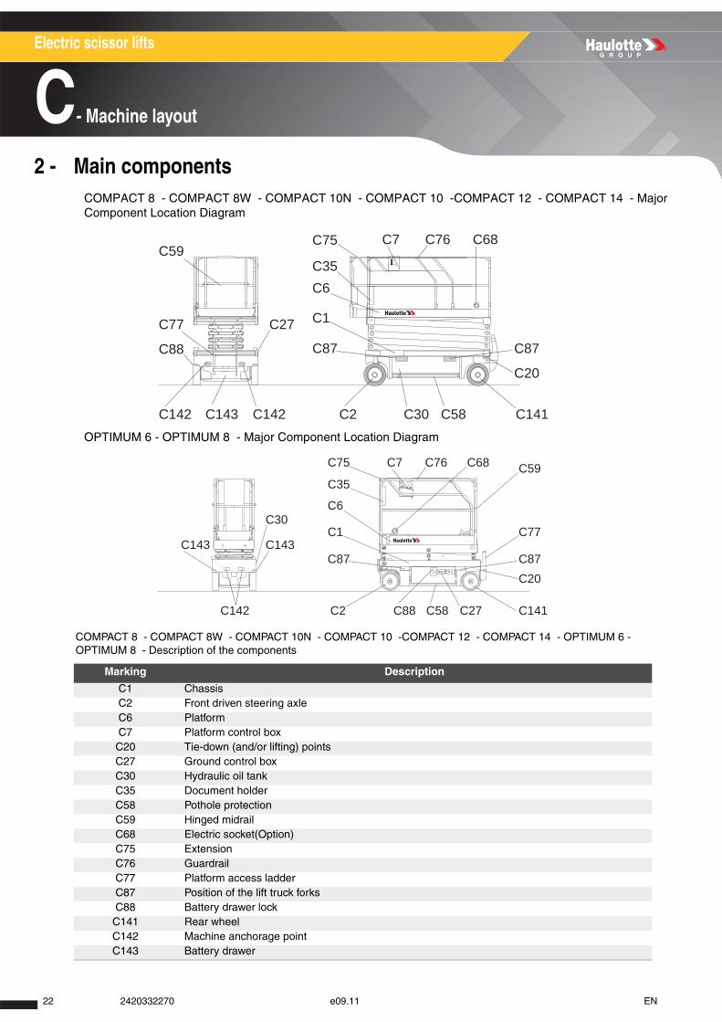
2 - Main componentsCOMPACT 8 - COMPACT 8W - COMPACT 10N - COMPACT 10 -COMPACT 12 - COMPACT 14 - Major Component Location Diagram
OPTIMUM 6 - OPTIMUM 8 - Major Component Location Diagram
COMPACT 8 - COMPACT 8W - COMPACT 10N - COMPACT 10 -COMPACT 12 - COMPACT 14 - OPTIMUM 6 - OPTIMUM 8 - Description of the components
Marking Description
C1 ChassisC2 Front driven steering axleC6 PlatformC7 Platform control boxC20 Tie-down (and/or lifting) pointsC27 Ground control boxC30 Hydraulic oil tankC35 Document holderC58 Pothole protectionC59 Hinged midrailC68 Electric socket(Option)C75 ExtensionC76 GuardrailC77 Platform access ladderC87 Position of the lift truck forksC88 Battery drawer lock
C141 Rear wheelC142 Machine anchorage pointC143 Battery drawer
C87 C87
C20
C1
C6C35
C75 C7 C68C76
C2C142
C77
C59
C27
C88
C143 C142 C30 C58 C141
C59
C77
C87C20
C87
C1
C6
C35
C75 C7 C68C76
C141C27C58C88C2
C143
C30
C143
C142
22 2420332270 e09.11 EN
A
B
C
D
E
F
G
H
I
Electric scissor lifts
C- Machine layout
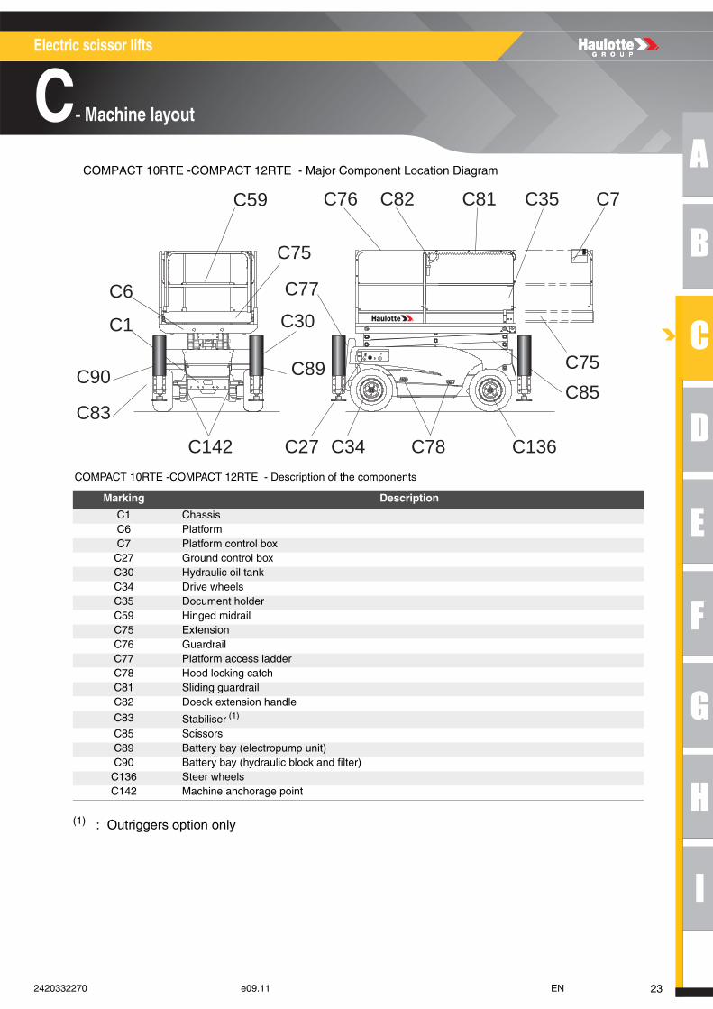
COMPACT 10RTE -COMPACT 12RTE - Major Component Location Diagram
COMPACT 10RTE -COMPACT 12RTE - Description of the components
(1) : Outriggers option only
Marking Description
C1 ChassisC6 PlatformC7 Platform control boxC27 Ground control boxC30 Hydraulic oil tankC34 Drive wheelsC35 Document holderC59 Hinged midrailC75 ExtensionC76 GuardrailC77 Platform access ladderC78 Hood locking catchC81 Sliding guardrailC82 Doeck extension handle
C83 Stabiliser (1)
C85 ScissorsC89 Battery bay (electropump unit)C90 Battery bay (hydraulic block and filter)
C136 Steer wheelsC142 Machine anchorage point
C27C142
C77
C30
C75
C89C90
C1
C6
C59
C34 C78
C75C85
C7C35C76 C82 C81
C136
C83
232420332270 e09.11 EN
Electric scissor lifts
C- Machine layout
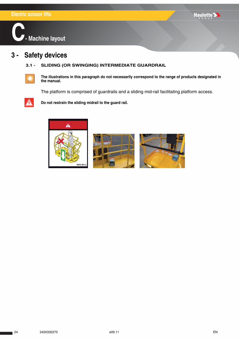
3 - Safety devices 3.1 - SLIDING (OR SWINGING) INTERMEDIATE GUARDRAIL
The platform is comprised of guardrails and a sliding mid-rail facilitating platform access.
The illustrations in this paragraph do not necessarily correspond to the range of products designated inthe manual.
Do not restrain the sliding midrail to the guard rail.
24 2420332270 e09.11 EN
A
B
C
D
E
F
G
H
I
Electric scissor lifts
C- Machine layout
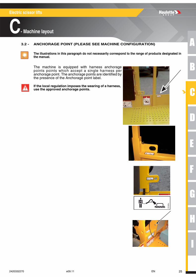
3.2 - ANCHORAGE POINT (PLEASE SEE MACHINE CONFIGURATION)
The illustrations in this paragraph do not necessarily correspond to the range of products designated inthe manual.
The machine is equipped with harness anchoragepoints points which accept a single harness peranchorage point. The anchorage points are identified bythe presence of the Anchorage point label.
If the local regulation imposes the wearing of a harness, use the approved anchorage points.
252420332270 e09.11 EN
Electric scissor lifts
C- Machine layout
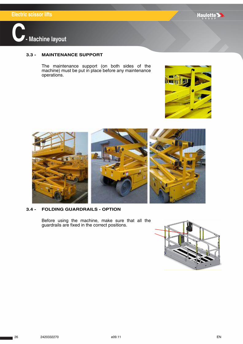
3.3 - MAINTENANCE SUPPORT
3.4 - FOLDING GUARDRAILS - OPTION
The maintenance support (on both sides of themachine) must be put in place before any maintenanceoperations.
Before using the machine, make sure that all theguardrails are fixed in the correct positions.
26 2420332270 e09.11 EN
A
B
C
D
E
F
G
H
I
Electric scissor lifts
C- Machine layout
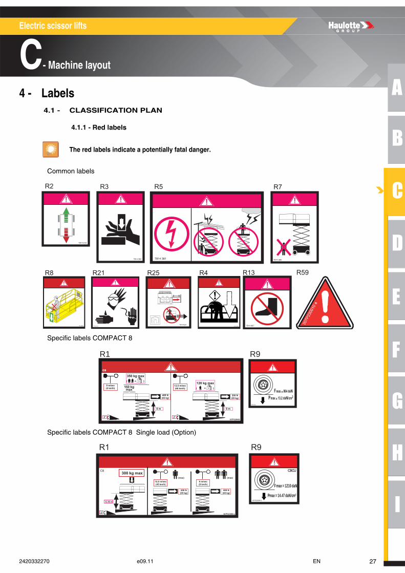
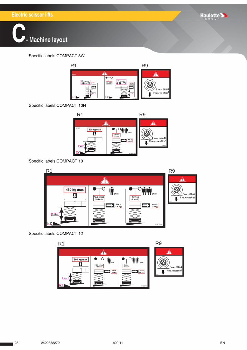
4 - Labels 4.1 - CLASSIFICATION PLAN
4.1.1 - Red labels
Common labels
Specific labels COMPACT 8
Specific labels COMPACT 8 Single load (Option)
The red labels indicate a potentially fatal danger.
R2
R8 R21 R25
R3 R5 R7
307P228390 a
R4 R59R13
R1 R9
C8CU
307P225640 a
F max = 1210 daN
Pmax = 14.47 daN/cm²200 N(20 kg)
12,5 m/sec(45 km/h)
(max) (max)
400 N(40 kg)
0 m/sec(0 km/h)
307P223960 a
300 kg max}
6,18 m
2°
C8
R9R1
272420332270 e09.11 EN
Electric scissor lifts
C- Machine layout
Specific labels COMPACT 8W
Specific labels COMPACT 10N
Specific labels COMPACT 10
Specific labels COMPACT 12
R1 R9
R1 R9
R1 R9
R1 R9
28 2420332270 e09.11 EN
A
B
C
D
E
F
G
H
I
Electric scissor lifts
C- Machine layout
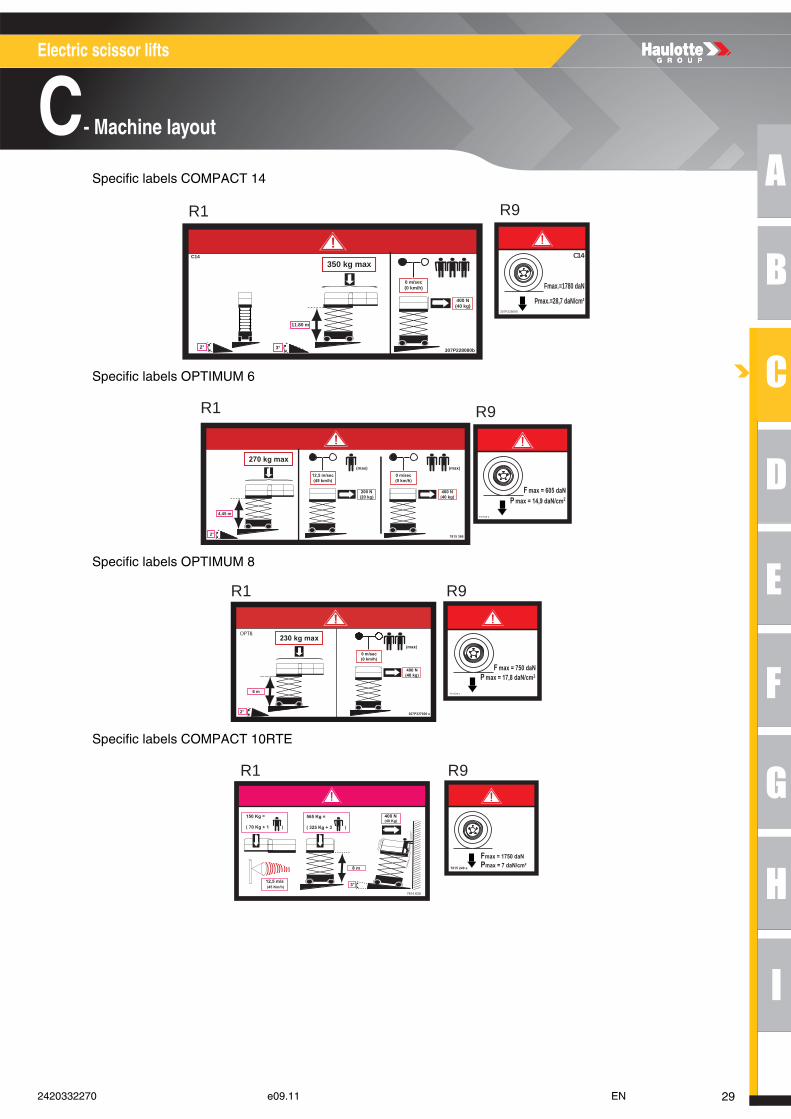
Specific labels COMPACT 14
Specific labels OPTIMUM 6
Specific labels OPTIMUM 8
Specific labels COMPACT 10RTE
R1 R9
400 N(40 kg)
0 m/sec(0 km/h)
350 kg max}11.80 m
3°2° 307P228080b
C14
Fmax.=1780 daN
307P228090
C14
Pmax.=28,7 daN/cm²
R1 R9
R1 R9
R1 R9
292420332270 e09.11 EN
Electric scissor lifts
C- Machine layout
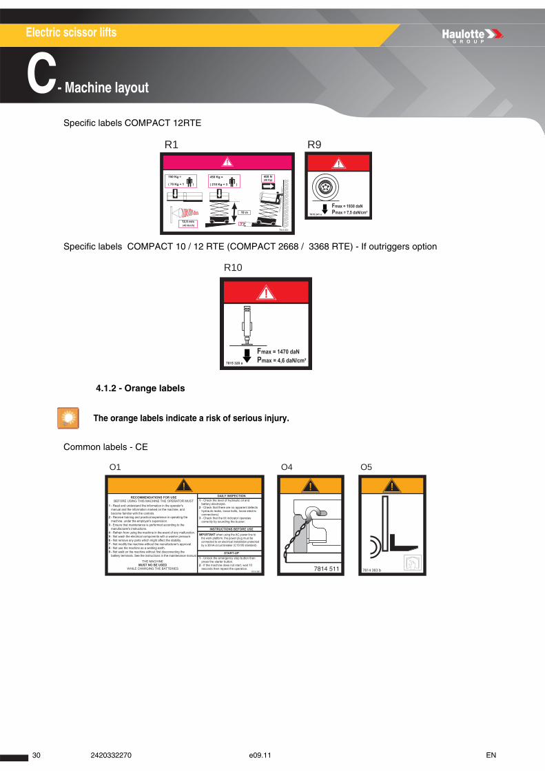
Specific labels COMPACT 12RTE
Specific labels COMPACT 10 / 12 RTE (COMPACT 2668 / 3368 RTE) - If outriggers option
4.1.2 - Orange labels
Common labels - CE
The orange labels indicate a risk of serious injury.
R1 R9
R10
O4O1 O5
30 2420332270 e09.11 EN
A
B
C
D
E
F
G
H
I
Electric scissor lifts
C- Machine layout
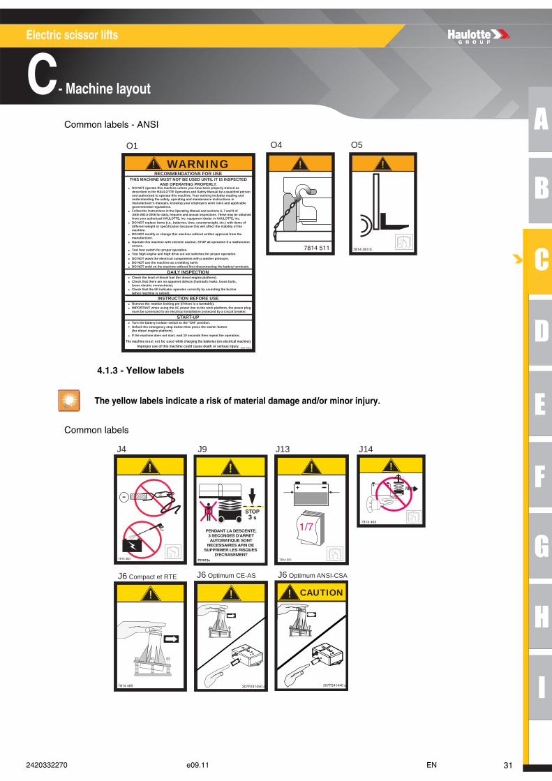
Common labels - ANSI
4.1.3 - Yellow labels
Common labels
The yellow labels indicate a risk of material damage and/or minor injury.
O4O1 O5
7814 705 b
WARNINGTHIS MACHINE MUST NOT BE USED UNTIL IT IS INSPECTED
AND OPERATING PROPERLY.DO NOT operate this machine unless you have been properly trained asdescribed in the HAULOTTE Operation and Safety Manual by a qualified person and authorized to operate this machine. Your training includes reading and understanding the safety, operating and maintenance instructions in manufacturer's manuals, knowing your employers work rules and applicable governmental regulations.
Follow the instructions in the Operating Manual and sections 6, 7 and 8 ofANSI A92.5-2006 for daily, frequent and annual inspections. These may be obtainedfrom your authorized HAULOTTE, Inc. equipment dealer or HAULOTTE, Inc.DO NOT replace items (i.e., batteries, tires, counterweight, etc.) with items ofdifferent weight or specification because this will affect the stability of themachine.DO NOT modify or change this machine without written approval from themanufacturer.Operate this machine with extreme caution. STOP all operation if a malfunctionoccurs.Test foot switch for proper operation.
RECOMMENDATIONS FOR USE
DAILY INSPECTION
INSTRUCTION BEFORE USE
Test high engine and high drive cut out switches for proper operation.DO NOT wash the electrical components with a washer pressure.DO NOT use the machine as a welding earth.DO NOT weld on the machine without first disconnecting the battery terminals.
Check the level of diesel fuel (for diesel engine platform).Check that there are no apparent defects (hydraulic leaks, loose bolts,loose electric connections).Check that the tilt indicator operates correctly by sounding the buzzer(when machine is raised).
Remove the rotation locking pin (if there is a turntable).IMPORTANT when using the AC power line to the work platform, the power plugmust be connected to an electrical installation protected by a circuit breaker.
START-UPTurn the battery isolater switch to the "ON" position.Unlock the emergency stop button then press the starter button(for diesel engine platform).If the machine does not start, wait 10 seconds then repeat the operation.
The machine must not be used while charging the batteries (on electrical machine)Improper use of this machine could cause death or serious injury.
.
.
.
.
.
.....
..
.
.
.
.
.
.
J4
J6 Compact et RTE
J9 J13 J14
307P241440 a
CAUTION
307P241450 a
J6 Optimum CE-AS J6 Optimum ANSI-CSA
312420332270 e09.11 EN
Electric scissor lifts
C- Machine layout
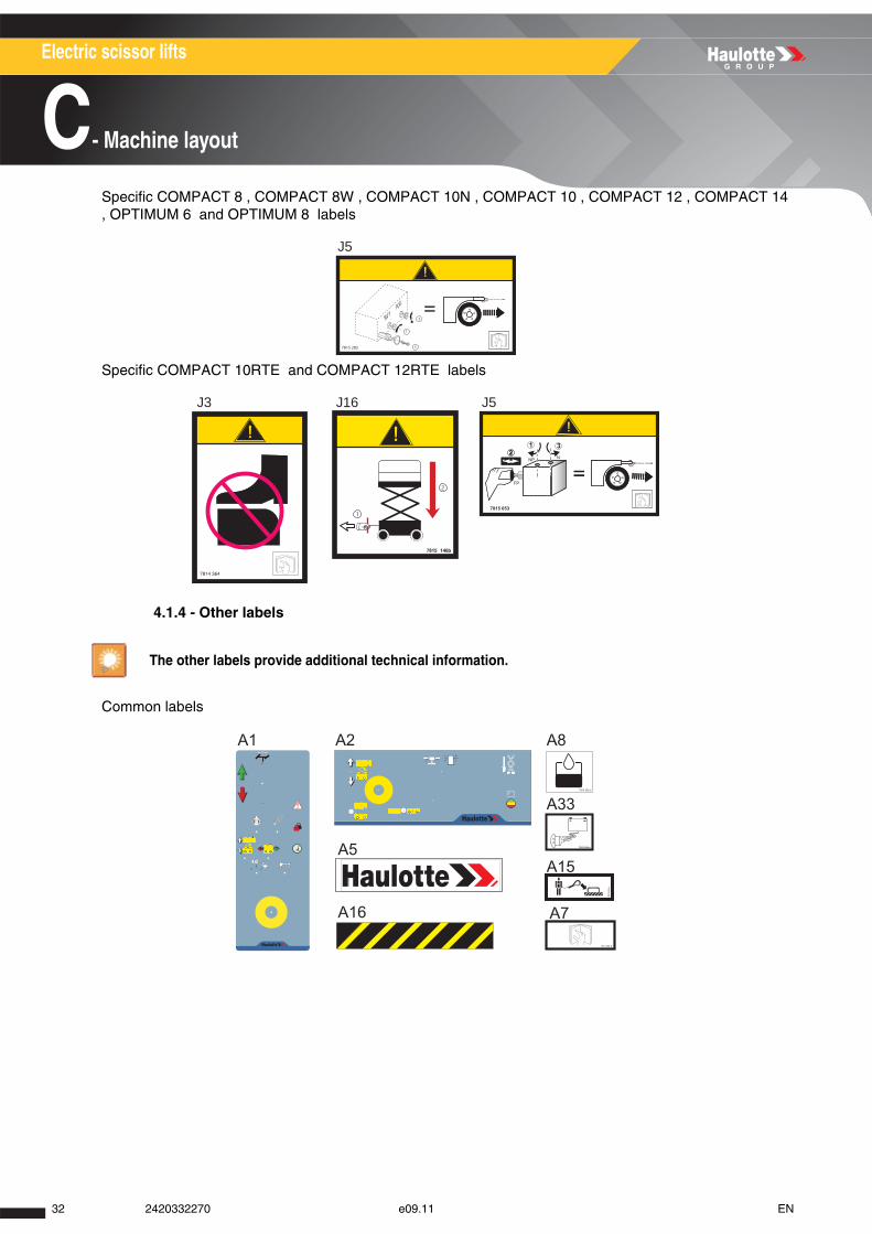
Specific COMPACT 8 , COMPACT 8W , COMPACT 10N , COMPACT 10 , COMPACT 12 , COMPACT 14 , OPTIMUM 6 and OPTIMUM 8 labels
Specific COMPACT 10RTE and COMPACT 12RTE labels
4.1.4 - Other labels
Common labels
The other labels provide additional technical information.
J5
J3 J16 J5
A5
A1 A2 A8
A33
A15
A16 A7
32 2420332270 e09.11 EN
A
B
C
D
E
F
G
H
I
Electric scissor lifts
C- Machine layout
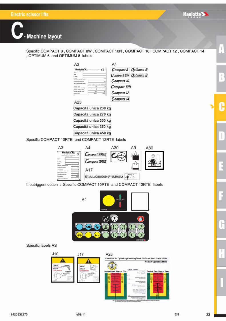
Specific COMPACT 8 , COMPACT 8W , COMPACT 10N , COMPACT 10 , COMPACT 12 , COMPACT 14 , OPTIMUM 6 and OPTIMUM 8 labels
Specific COMPACT 10RTE and COMPACT 12RTE labels
If outriggers option : Specific COMPACT 10RTE and COMPACT 12RTE labels
Specific labels AS
A3
A23
A4
7814
514
a
Capacità unica 230 kg307P227590
3 07P
227 2
50a 4
A3 A4
A17
A30 A9
A80
A1
J10 J17
a
A28
332420332270 e09.11 EN
Electric scissor lifts
C- Machine layout
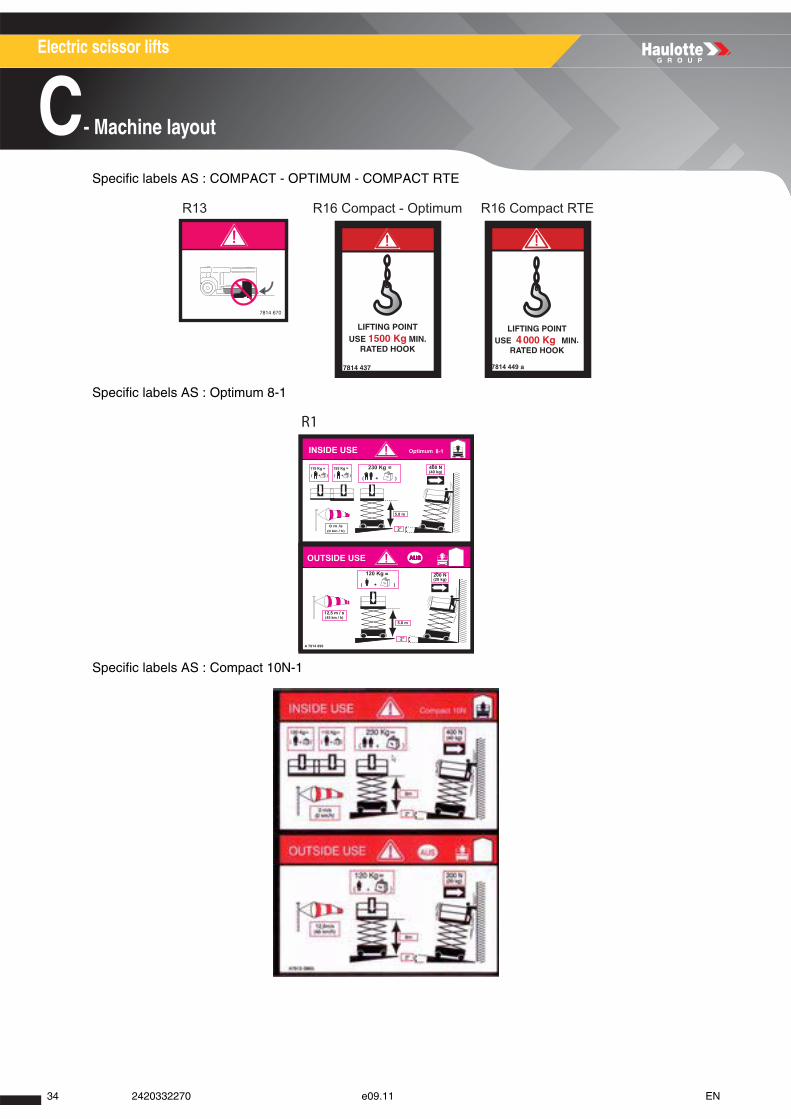
Specific labels AS : COMPACT - OPTIMUM - COMPACT RTE
Specific labels AS : Optimum 8-1
Specific labels AS : Compact 10N-1
R16 Compact - OptimumR13
7814 449 a
R16 Compact RTE
R1
34 2420332270 e09.11 EN
A
B
C
D
E
F
G
H
I
Electric scissor lifts
C- Machine layout
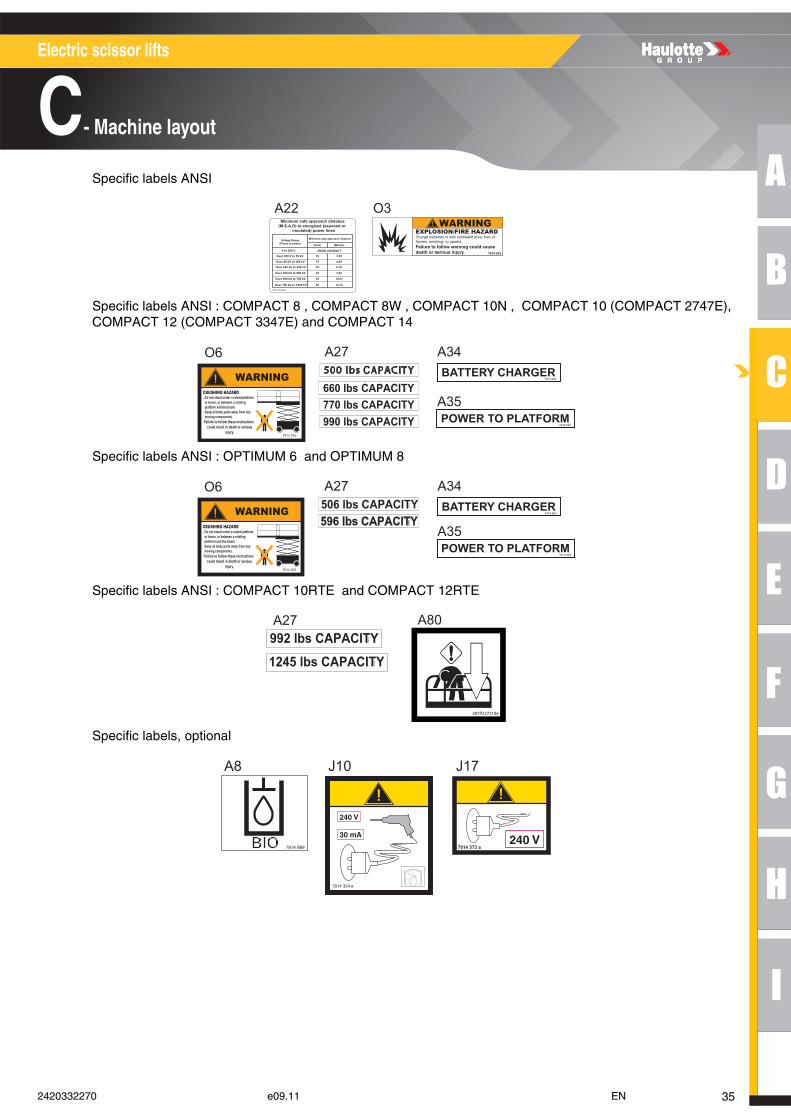
Specific labels ANSI
Specific labels ANSI : COMPACT 8 , COMPACT 8W , COMPACT 10N , COMPACT 10 (COMPACT 2747E), COMPACT 12 (COMPACT 3347E) and COMPACT 14
Specific labels ANSI : OPTIMUM 6 and OPTIMUM 8
Specific labels ANSI : COMPACT 10RTE and COMPACT 12RTE
Specific labels, optional
A22 O3Minimum safe approach distance
(M.S.A.D) to energized (exposed or insulated) power lines
Voltage Range(Phase to phase)
Minimum safe approach distance
0 to 300 V
Over 300 V to 50 kV
Over 50 kV to 200 kV
Over 200 kV to 350 kV
Over 350 kV to 500 kV
Over 500 kV to 750 kV
Over 750 kV to 1000 kV
AVOID CONTACT
10
15
20
25
35
45
3.05
4.60
6.10
7.62
10.67
13.723078147890 c
(Feet) (Meters)
O6 A27 A34
A35
O6 A27 A34
A35
A27
307P227210a
A80
A8 J10 J17
a
7814 573 a
352420332270 e09.11 EN
Electric scissor lifts
C- Machine layout
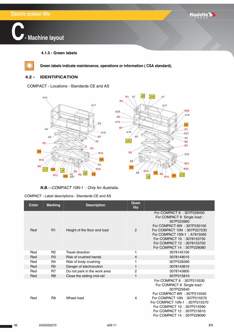
4.1.5 - Green labels
4.2 - IDENTIFICATION
COMPACT - Locations - Standards CE and AS
N.B.-:-COMPACT 10N-1 : Only for Australia.
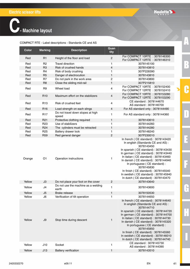
COMPACT - Label descriptions - Standards CE and AS
Green labels indicate maintenance, operations or information ( CSA standard).
Color Marking DescriptionQuantity
Red R1 Height of the floor and load 2
For COMPACT 8 : 307P228400For COMPACT 8 Single load :
307P223960For COMPACT 8W : 307P230100For COMPACT 10N : 307P227230For COMPACT 10N-1 : A7815095For COMPACT 10 : 3078153730For COMPACT 12 : 3078153750For COMPACT 14 : 307P228080
Red R2 Travel direction 1 3078145100Red R3 Risk of crushed hands 4 3078149010Red R4 Risk of body crushing 1 307P228390Red R5 Danger of electrocution 1 3078143810Red R7 Do not park in the work area 2 3078143800Red R8 Close the sliding mid-rail 1 307P215810
Red R9 Wheel load 4
For COMPACT 8 : 307P215530For COMPACT 8 Single load :
307P225640For COMPACT 8W : 307P215550For COMPACT 10N : 307P215570
For COMPACT 10N-1 : 307P215570For COMPACT 10 : 307P215590For COMPACT 12 : 307P215610For COMPACT 14 : 307P228090
A4
A5
R3
R9
R13
R16
A2
A3
R9
R16
R16
R3
R9
A5
A16
R16
A15
A28
A15
R7R2
R5
R1 A7 R2
A1
A4
A15R59
R8R3
R21
A33
R25A8 R9
R13
R1
R4
O5O4
O1
O4O5
O5J17 J4
J6
J9 J14
J10
J13J5
O4
O5
O4
A5
R3
R7A16
A17
A23
A87
A17
36 2420332270 e09.11 EN

A
B
C
D
E
F
G
H
I
Electric scissor lifts
C- Machine layout
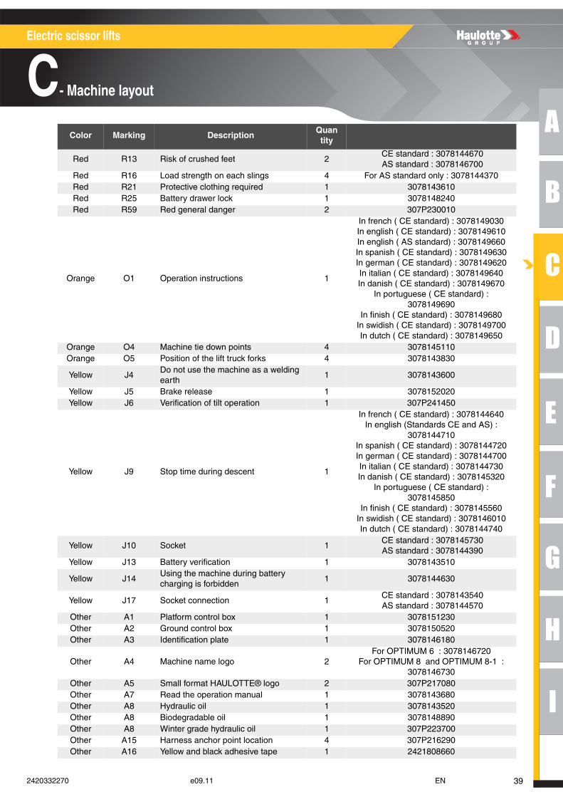
Red R13 Risk of crushed feet 2CE standard : 3078144670AS standard : 3078146700
Red R16 Load strength on each slings 4 For AS standard only : 3078144370Red R21 Protective clothing required 1 3078143610Red R25 Battery drawer lock 1 3078145310Red R59 Red general danger 2 307P230010
Orange O1 Operation instructions 1
In french ( CE standard) : 3078149030In english ( CE standard) : 3078149610In english ( AS standard) : 3078149660In spanish ( CE standard) : 3078149630In german ( CE standard) : 3078149620In italian ( CE standard) : 3078149640In danish ( CE standard) : 3078149670
In portuguese ( CE standard) : 3078149690
In finish ( CE standard) : 3078149680In swidish ( CE standard) : 3078149700In dutch ( CE standard) : 3078149650
Orange O4 Machine tie down points 4 3078145110Orange O5 Position of the lift truck forks 4 3078143830
Yellow J4Do not use the machine as a welding earth
1 3078143600
Yellow J5 Brake release 1 3078152020Yellow J6 Verification of tilt operation 1 3078144650
Yellow J9 Stop time during descent 1
In french ( CE standard) : 3078144640In english (Standards CE and AS) :
3078144710In spanish ( CE standard) : 3078144720In german ( CE standard) : 3078144700In italian ( CE standard) : 3078144730In danish ( CE standard) : 3078145320
In portuguese ( CE standard) : 3078145850
In finish ( CE standard) : 3078145560In swidish ( CE standard) : 3078146010In dutch ( CE standard) : 3078144740
Yellow J10 Socket 1CE standard : 3078145730AS standard : 3078144390
Yellow J13 Battery verification 1 3078143510
Yellow J14Using the machine during battery charging is forbidden
1 3078144630
Yellow J17 Socket connection 1CE standard : 3078143540AS standard : 3078144570
Other A1 Platform control box 1 3078151230Other A2 Ground control box 1 3078145060Other A3 Identification plate 1 3078146180
Other A4 Machine name logo 2
For COMPACT 8 and COMPACT 8 Single load : 3078145120
For COMPACT 8W : 3078145130For COMPACT 10N and COMPACT 10N-
1 : 3078150900For COMPACT 10 : 3078145140For COMPACT 12 : 3078145150For COMPACT 14 : 307P227250
Other A5 Small format HAULOTTE® logo 2 307P217080Other A7 Read the operation manual 1 3078143680
Color Marking DescriptionQuantity
372420332270 e09.11 EN
Electric scissor lifts
C- Machine layout
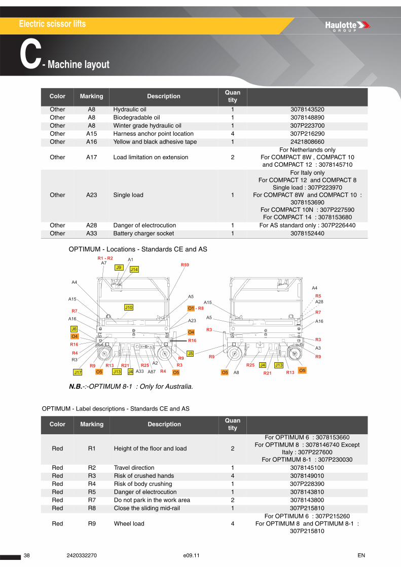
OPTIMUM - Locations - Standards CE and AS
N.B.-:-OPTIMUM 8-1 : Only for Australia.
OPTIMUM - Label descriptions - Standards CE and AS
Other A8 Hydraulic oil 1 3078143520Other A8 Biodegradable oil 1 3078148890Other A8 Winter grade hydraulic oil 1 307P223700Other A15 Harness anchor point location 4 307P216290Other A16 Yellow and black adhesive tape 1 2421808660
Other A17 Load limitation on extension 2For Netherlands only
For COMPACT 8W , COMPACT 10 and COMPACT 12 : 3078145710
Other A23 Single load 1
For Italy onlyFor COMPACT 12 and COMPACT 8
Single load : 307P223970For COMPACT 8W and COMPACT 10 :
3078153690For COMPACT 10N : 307P227590For COMPACT 14 : 3078153680
Other A28 Danger of electrocution 1 For AS standard only : 307P226440Other A33 Battery charger socket 1 3078152440
Color Marking DescriptionQuantity
Red R1 Height of the floor and load 2
For OPTIMUM 6 : 3078153660For OPTIMUM 8 : 3078146740 Except
Italy : 307P227600For OPTIMUM 8-1 : 307P230030
Red R2 Travel direction 1 3078145100Red R3 Risk of crushed hands 4 3078149010Red R4 Risk of body crushing 1 307P228390Red R5 Danger of electrocution 1 3078143810Red R7 Do not park in the work area 2 3078143800Red R8 Close the sliding mid-rail 1 307P215810
Red R9 Wheel load 4For OPTIMUM 6 : 307P215260
For OPTIMUM 8 and OPTIMUM 8-1 : 307P215810
Color Marking DescriptionQuantity
J10
A4
R1 - R2
J9
A1
J14
R7
J6
O4
J17
R16
R3R9 A2
A8
J4O5O5
J13
R13
R9
A3
A16
R3
R7
A28R5
A4
R25
R21O5O5R3R9
R16
R9J5
O4
A5
R3
A5
A15O1 - R8
A23
R13 R21A33
R25J13 J4
A16
A15
R4
R4
R59A7
A87
38 2420332270 e09.11 EN
A
B
C
D
E
F
G
H
I
Electric scissor lifts
C- Machine layout
Red R13 Risk of crushed feet 2CE standard : 3078144670AS standard : 3078146700
Red R16 Load strength on each slings 4 For AS standard only : 3078144370Red R21 Protective clothing required 1 3078143610Red R25 Battery drawer lock 1 3078148240Red R59 Red general danger 2 307P230010
Orange O1 Operation instructions 1
In french ( CE standard) : 3078149030In english ( CE standard) : 3078149610In english ( AS standard) : 3078149660In spanish ( CE standard) : 3078149630In german ( CE standard) : 3078149620In italian ( CE standard) : 3078149640In danish ( CE standard) : 3078149670
In portuguese ( CE standard) : 3078149690
In finish ( CE standard) : 3078149680In swidish ( CE standard) : 3078149700In dutch ( CE standard) : 3078149650
Orange O4 Machine tie down points 4 3078145110Orange O5 Position of the lift truck forks 4 3078143830
Yellow J4Do not use the machine as a welding earth
1 3078143600
Yellow J5 Brake release 1 3078152020Yellow J6 Verification of tilt operation 1 307P241450
Yellow J9 Stop time during descent 1
In french ( CE standard) : 3078144640In english (Standards CE and AS) :
3078144710In spanish ( CE standard) : 3078144720In german ( CE standard) : 3078144700In italian ( CE standard) : 3078144730In danish ( CE standard) : 3078145320
In portuguese ( CE standard) : 3078145850
In finish ( CE standard) : 3078145560In swidish ( CE standard) : 3078146010In dutch ( CE standard) : 3078144740
Yellow J10 Socket 1CE standard : 3078145730AS standard : 3078144390
Yellow J13 Battery verification 1 3078143510
Yellow J14Using the machine during battery charging is forbidden
1 3078144630
Yellow J17 Socket connection 1CE standard : 3078143540AS standard : 3078144570
Other A1 Platform control box 1 3078151230Other A2 Ground control box 1 3078150520Other A3 Identification plate 1 3078146180
Other A4 Machine name logo 2For OPTIMUM 6 : 3078146720
For OPTIMUM 8 and OPTIMUM 8-1 : 3078146730
Other A5 Small format HAULOTTE® logo 2 307P217080Other A7 Read the operation manual 1 3078143680Other A8 Hydraulic oil 1 3078143520Other A8 Biodegradable oil 1 3078148890Other A8 Winter grade hydraulic oil 1 307P223700Other A15 Harness anchor point location 4 307P216290Other A16 Yellow and black adhesive tape 1 2421808660
Color Marking DescriptionQuantity
392420332270 e09.11 EN
Electric scissor lifts
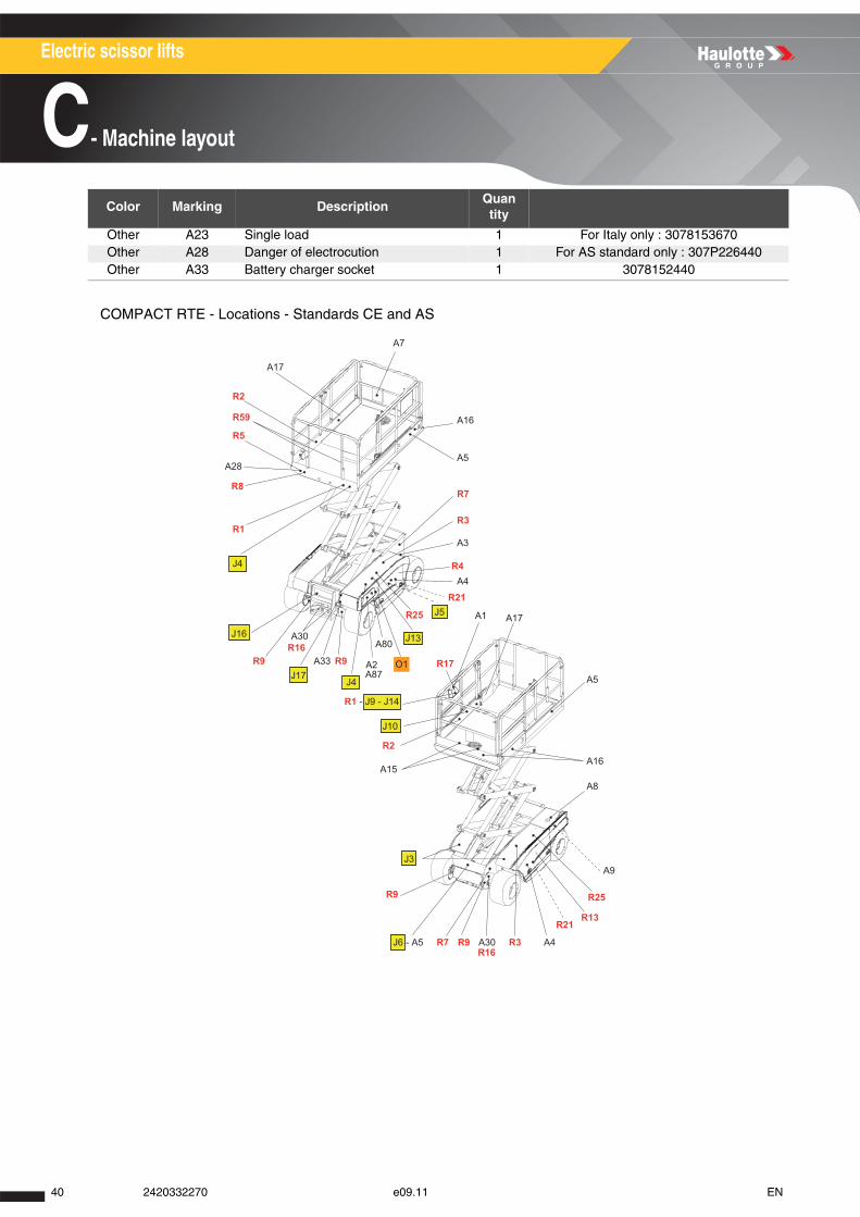
C- Machine layout
COMPACT RTE - Locations - Standards CE and AS
Other A23 Single load 1 For Italy only : 3078153670Other A28 Danger of electrocution 1 For AS standard only : 307P226440Other A33 Battery charger socket 1 3078152440
Color Marking DescriptionQuantity
A80
A7
R2
R59
R5
A28
R8
R1
R9 R9
J4
A2
R1 - J9 - J14
J10
R2
A15
O1
J13
R25 J5
A4
A1
A5
A16
A8
A9
A4A30 R3R9R7
R9
J3
J6 - A5
R25
R21
A3
R7
A16
A5
R3
R21
J17
A30
A33
J16
J4 R4
R13
R16
R16
R17
A17
A17
A87
40 2420332270 e09.11 EN
A
B
C
D
E
F
G
H
I
Electric scissor lifts
C- Machine layout
COMPACT RTE - Label descriptions - Standards CE and AS
Color Marking DescriptionQuantity
Red R1 Height of the floor and load 2For COMPACT 10RTE : 3078146300For COMPACT 12RTE : 3078146310
Red R2 Travel direction 1 3078145100Red R3 Risk of crushed hands 4 3078143810Red R4 Risk of body crushing 1 307P228390Red R5 Danger of electrocution 1 3078143810Red R7 Do not park in the work area 2 3078143800Red R8 Close the sliding mid-rail 1 307P215810
Red R9 Wheel load 4For COMPACT 10RTE : 3078152400For COMPACT 12RTE : 3078152410
Red R10 Maximum effort on the stabilizers 4For COMPACT 10RTE : 3078153280For COMPACT 12RTE : 3078153290
Red R13 Risk of crushed feet 4CE standard : 3078144670AS standard : 3078146700
Red R16 Load strength on each slings 4 For AS standard only : 3078144490
Red R17Do not travel down slopes at high speed
1 For AS standard only : 3078144360
Red R21 Protective clothing required 1 3078143610Red R23 Use of stabilizers 1 3078144260Red R24 The cylinders must be retracted 1 3078144280Red R25 Battery drawer lock 1 3078148240Red R59 Red general danger 2 307P230010
Orange O1 Operation instructions 1
In french ( CE standard) : 3078143420In english (Standards CE and AS) :
3078143450In spanish ( CE standard) : 3078143430In german ( CE standard) : 3078143440In italian ( CE standard) : 3078143460In danish ( CE standard) : 3078144940
In portuguese ( CE standard) : 3078145830
In finish ( CE standard) : 3078145540In swidish ( CE standard) : 3078145940In dutch ( CE standard) : 3078143470
Yellow J3 Do not place your foot on the cover 2 3078143640
Yellow J4Do not use the machine as a welding earth
1 3078143600
Yellow J5 Brake release 1 3078150530Yellow J6 Verification of tilt operation 1 3078144650
Yellow J9 Stop time during descent 1
In french ( CE standard) : 3078144640In english (Standards CE and AS) :
3078144710In spanish ( CE standard) : 3078144720In german ( CE standard) : 3078144700In italian ( CE standard) : 3078144730In danish ( CE standard) : 3078145320
In portuguese ( CE standard) : 3078145850
In finish ( CE standard) : 3078145560In swidish ( CE standard) : 3078146010In dutch ( CE standard) : 3078144740
Yellow J10 Socket 1CE standard : 3078145730AS standard : 3078144390
Yellow J13 Battery verification 1 3078143510
412420332270 e09.11 EN
Electric scissor lifts
C- Machine layout
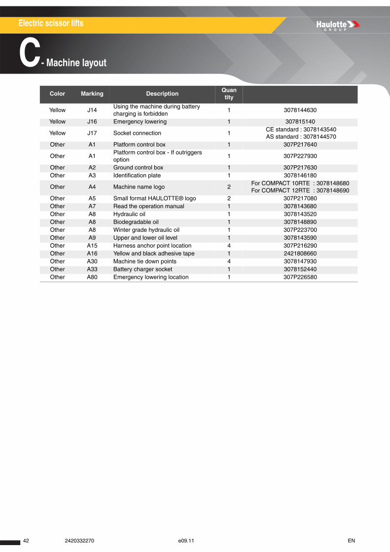
Yellow J14Using the machine during battery charging is forbidden
1 3078144630
Yellow J16 Emergency lowering 1 307815140
Yellow J17 Socket connection 1CE standard : 3078143540AS standard : 3078144570
Other A1 Platform control box 1 307P217640
Other A1Platform control box - If outriggers option
1 307P227930
Other A2 Ground control box 1 307P217630Other A3 Identification plate 1 3078146180
Other A4 Machine name logo 2For COMPACT 10RTE : 3078148680For COMPACT 12RTE : 3078148690
Other A5 Small format HAULOTTE® logo 2 307P217080Other A7 Read the operation manual 1 3078143680Other A8 Hydraulic oil 1 3078143520Other A8 Biodegradable oil 1 3078148890Other A8 Winter grade hydraulic oil 1 307P223700Other A9 Upper and lower oil level 1 3078143590Other A15 Harness anchor point location 4 307P216290Other A16 Yellow and black adhesive tape 1 2421808660Other A30 Machine tie down points 4 3078147930Other A33 Battery charger socket 1 3078152440Other A80 Emergency lowering location 1 307P226580
Color Marking DescriptionQuantity
42 2420332270 e09.11 EN
A
B
C
D
E
F
G
H
I
Electric scissor lifts
C- Machine layout
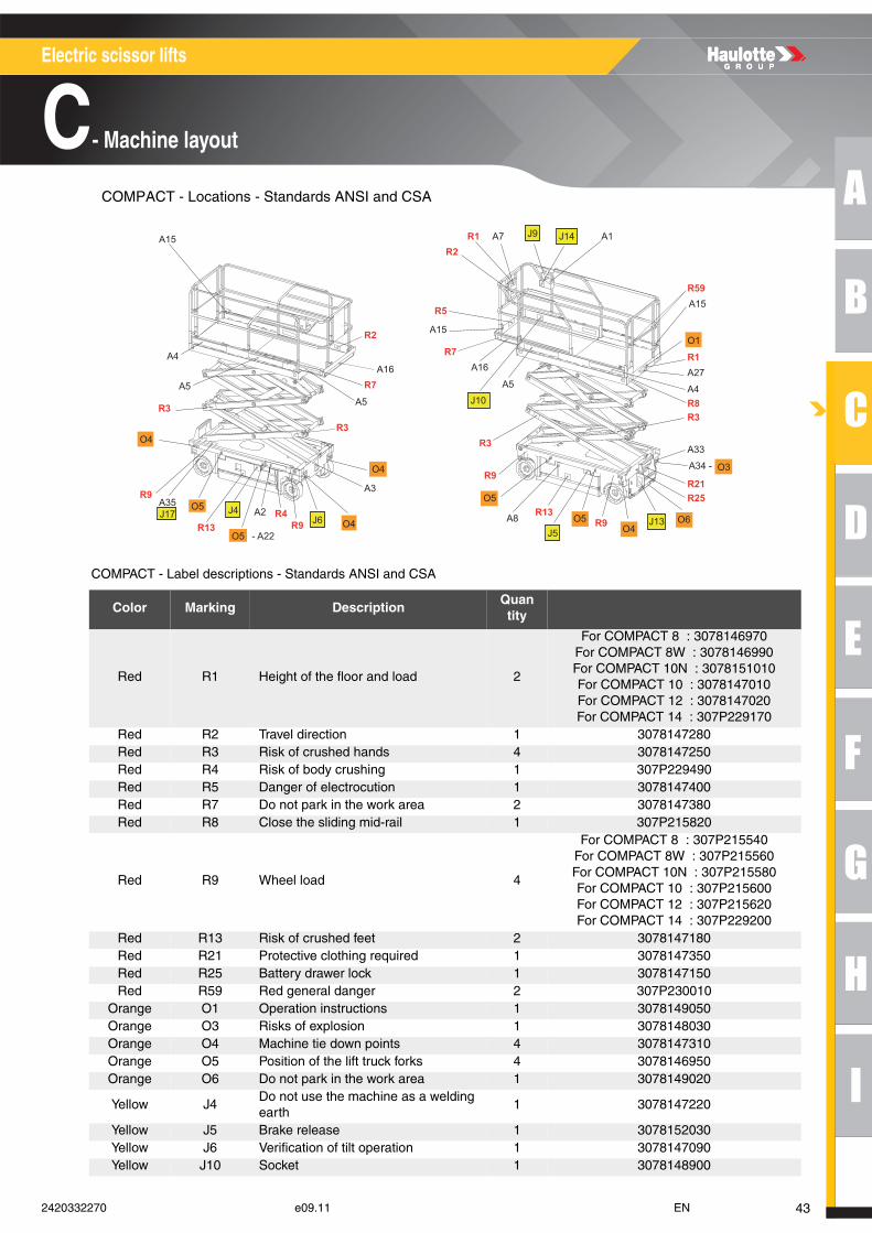
COMPACT - Locations - Standards ANSI and CSA
COMPACT - Label descriptions - Standards ANSI and CSA
Color Marking DescriptionQuantity
Red R1 Height of the floor and load 2
For COMPACT 8 : 3078146970For COMPACT 8W : 3078146990For COMPACT 10N : 3078151010For COMPACT 10 : 3078147010For COMPACT 12 : 3078147020For COMPACT 14 : 307P229170
Red R2 Travel direction 1 3078147280Red R3 Risk of crushed hands 4 3078147250Red R4 Risk of body crushing 1 307P229490Red R5 Danger of electrocution 1 3078147400Red R7 Do not park in the work area 2 3078147380Red R8 Close the sliding mid-rail 1 307P215820
Red R9 Wheel load 4
For COMPACT 8 : 307P215540For COMPACT 8W : 307P215560For COMPACT 10N : 307P215580For COMPACT 10 : 307P215600For COMPACT 12 : 307P215620For COMPACT 14 : 307P229200
Red R13 Risk of crushed feet 2 3078147180Red R21 Protective clothing required 1 3078147350Red R25 Battery drawer lock 1 3078147150Red R59 Red general danger 2 307P230010
Orange O1 Operation instructions 1 3078149050Orange O3 Risks of explosion 1 3078148030Orange O4 Machine tie down points 4 3078147310Orange O5 Position of the lift truck forks 4 3078146950Orange O6 Do not park in the work area 1 3078149020
Yellow J4Do not use the machine as a welding earth
1 3078147220
Yellow J5 Brake release 1 3078152030Yellow J6 Verification of tilt operation 1 3078147090Yellow J10 Socket 1 3078148900
A4
A5
R3
R9
R13A2
A3
R9
R3
R9
A5
A16
A15
A15
R7R2
R5
R1 A7 R2
A1
A4
A27
A15R59
R8R3
R21
A33
R25
A8 R9R13
R1
R4
O5O4
O1
O4O5
O5J4
J6
J9 J14
J10
J13J5
O4
O5
O4
A5
R3
R7A16
A35
A34 - O3
- A22
J17 O6
432420332270 e09.11 EN
Electric scissor lifts
C- Machine layout
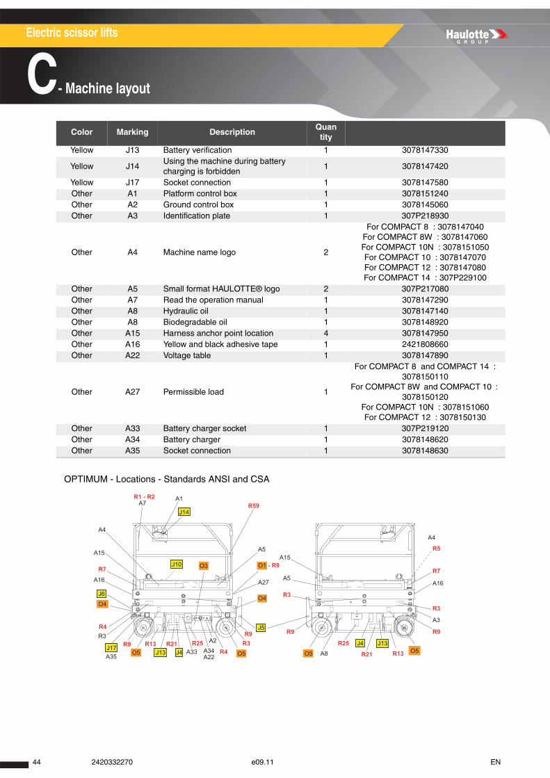
OPTIMUM - Locations - Standards ANSI and CSA
Yellow J13 Battery verification 1 3078147330
Yellow J14Using the machine during battery charging is forbidden
1 3078147420
Yellow J17 Socket connection 1 3078147580Other A1 Platform control box 1 3078151240Other A2 Ground control box 1 3078145060Other A3 Identification plate 1 307P218930
Other A4 Machine name logo 2
For COMPACT 8 : 3078147040For COMPACT 8W : 3078147060For COMPACT 10N : 3078151050For COMPACT 10 : 3078147070For COMPACT 12 : 3078147080For COMPACT 14 : 307P229100
Other A5 Small format HAULOTTE® logo 2 307P217080Other A7 Read the operation manual 1 3078147290Other A8 Hydraulic oil 1 3078147140Other A8 Biodegradable oil 1 3078148920Other A15 Harness anchor point location 4 3078147950Other A16 Yellow and black adhesive tape 1 2421808660Other A22 Voltage table 1 3078147890
Other A27 Permissible load 1
For COMPACT 8 and COMPACT 14 : 3078150110
For COMPACT 8W and COMPACT 10 : 3078150120
For COMPACT 10N : 3078151060For COMPACT 12 : 3078150130
Other A33 Battery charger socket 1 307P219120Other A34 Battery charger 1 3078148620Other A35 Socket connection 1 3078148630
Color Marking DescriptionQuantity
J10
A4
R1 - R2 A1
J14
R7
J6
O4
J17
R3R9 A2
A8
J4O5O5
J13
R13
R9
A3
A16
R3
R7
R5
A4
R25
R21O5O5R3R9 R9J5
O4
A5
R3
A5
A15O1 - R8
A27
R13 R21A33
R25J13 J4
A16
A15
R4
R4
R59A7
A34A22
O3
A35
44 2420332270 e09.11 EN
A
B
C
D
E
F
G
H
I
Electric scissor lifts
C- Machine layout
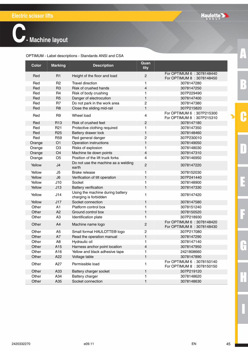
OPTIMUM - Label descriptions - Standards ANSI and CSA
Color Marking DescriptionQuantity
Red R1 Height of the floor and load 2For OPTIMUM 6 : 3078148440For OPTIMUM 8 : 3078148450
Red R2 Travel direction 1 3078147280Red R3 Risk of crushed hands 4 3078147250Red R4 Risk of body crushing 1 307P229490Red R5 Danger of electrocution 1 3078147400Red R7 Do not park in the work area 2 3078147380Red R8 Close the sliding mid-rail 1 307P215820
Red R9 Wheel load 4For OPTIMUM 6 : 307P215300For OPTIMUM 8 : 307P215310
Red R13 Risk of crushed feet 2 3078147180Red R21 Protective clothing required 1 3078147350Red R25 Battery drawer lock 1 3078148460Red R59 Red general danger 2 307P230010
Orange O1 Operation instructions 1 3078149050Orange O3 Risks of explosion 1 3078148030Orange O4 Machine tie down points 4 3078147310Orange O5 Position of the lift truck forks 4 3078146950
Yellow J4Do not use the machine as a welding earth
2 3078147220
Yellow J5 Brake release 1 3078152030Yellow J6 Verification of tilt operation 1 307P241440Yellow J10 Socket 1 3078148900Yellow J13 Battery verification 1 3078147330
Yellow J14Using the machine during battery charging is forbidden
1 3078147420
Yellow J17 Socket connection 1 3078147580Other A1 Platform control box 1 3078151240Other A2 Ground control box 1 3078150520Other A3 Identification plate 1 307P218930
Other A4 Machine name logo 2For OPTIMUM 6 : 3078148420For OPTIMUM 8 : 3078148430
Other A5 Small format HAULOTTE® logo 2 307P217080Other A7 Read the operation manual 1 3078147290Other A8 Hydraulic oil 1 3078147140Other A15 Harness anchor point location 4 3078147950Other A16 Yellow and black adhesive tape 1 2421808660Other A22 Voltage table 1 3078147890
Other A27 Permissible load 1For OPTIMUM 6 : 3078150140For OPTIMUM 8 : 3078150150
Other A33 Battery charger socket 1 307P219120Other A34 Battery charger 1 3078148620Other A35 Socket connection 1 3078148630
452420332270 e09.11 EN
Electric scissor lifts
C- Machine layout
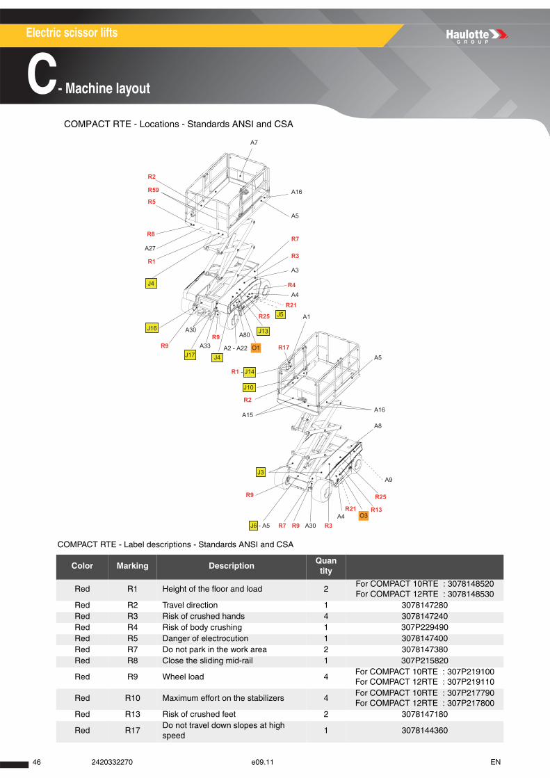
COMPACT RTE - Locations - Standards ANSI and CSA
COMPACT RTE - Label descriptions - Standards ANSI and CSA
Color Marking DescriptionQuantity
Red R1 Height of the floor and load 2For COMPACT 10RTE : 3078148520For COMPACT 12RTE : 3078148530
Red R2 Travel direction 1 3078147280Red R3 Risk of crushed hands 4 3078147240Red R4 Risk of body crushing 1 307P229490Red R5 Danger of electrocution 1 3078147400Red R7 Do not park in the work area 2 3078147380Red R8 Close the sliding mid-rail 1 307P215820
Red R9 Wheel load 4For COMPACT 10RTE : 307P219100For COMPACT 12RTE : 307P219110
Red R10 Maximum effort on the stabilizers 4For COMPACT 10RTE : 307P217790For COMPACT 12RTE : 307P217800
Red R13 Risk of crushed feet 2 3078147180
Red R17Do not travel down slopes at high speed
1 3078144360
A80
A7
R2
R59
R5
R8
R1
R9R9
J4A2 - A22
R1 - J14
J10
R2
A15
O1
J13
R25 J5
A4
A1
A5
A16
A8
A9
A4A30 R3R9R7
R9
J3
J6 - A5
R25
R21
A3
R7
A16
A5
R3
R21
J17
A30
A33
J16
J4 R4
R13
R17
O3
A27
46 2420332270 e09.11 EN

A
B
C
D
E
F
G
H
I
Electric scissor lifts
C- Machine layout
Red R21 Protective clothing required 1 3078147350Red R23 Use of stabilizers 1 3078144260Red R24 The cylinders must be retracted 1 3078144280Red R25 Battery drawer lock 1 3078148460Red R59 Red general danger 2 307P230010
Orange O1 Operation instructions 1 3078149050Orange O3 Risks of explosion 1 3078148030Yellow J3 Do not place your foot on the cover 2 3078147270
Yellow J4Do not use the machine as a welding earth
1 3078147220
Yellow J5 Brake release 1 3078150540Yellow J6 Verification of tilt operation 1 3078147090Yellow J10 Socket 1 3078148900Yellow J13 Battery verification 1 3078147330
Yellow J14Using the machine during battery charging is forbidden
2 3078147420
Yellow J16 Emergency lowering 1 3078151460Yellow J17 Socket connection 1 3078147580
Other A1Platform control boxIf outriggers option
1 307P227930
Other A1 Platform control box 1 307P218870Other A2 Ground control box 1 307P217630Other A3 Identification plate 1 307P218930
Other A4 Machine name logo 2For COMPACT 10RTE : 307P219080For COMPACT 12RTE : 307P219090
Other A5 Small format HAULOTTE® logo 2 307P217230Other A7 Read the operation manual 1 3078147290Other A8 Hydraulic oil 1 3078147140Other A9 Upper and lower oil level 1 3078147210Other A15 Harness anchor point location 4 3078147950Other A16 Yellow and black adhesive tape 1 2421808660Other A22 Voltage table 1 3078147890
Other A27 Permissible load 1For COMPACT 10RTE : 3078150090For COMPACT 12RTE : 3078150100
Other A30 Machine tie down points 4 3078147930Other A33 Battery charger socket 1 307P219120Other A80 Emergency lowering location 1 307P227210
Color Marking DescriptionQuantity
472420332270 e09.11 EN
Electric scissor lifts
C- Machine layout
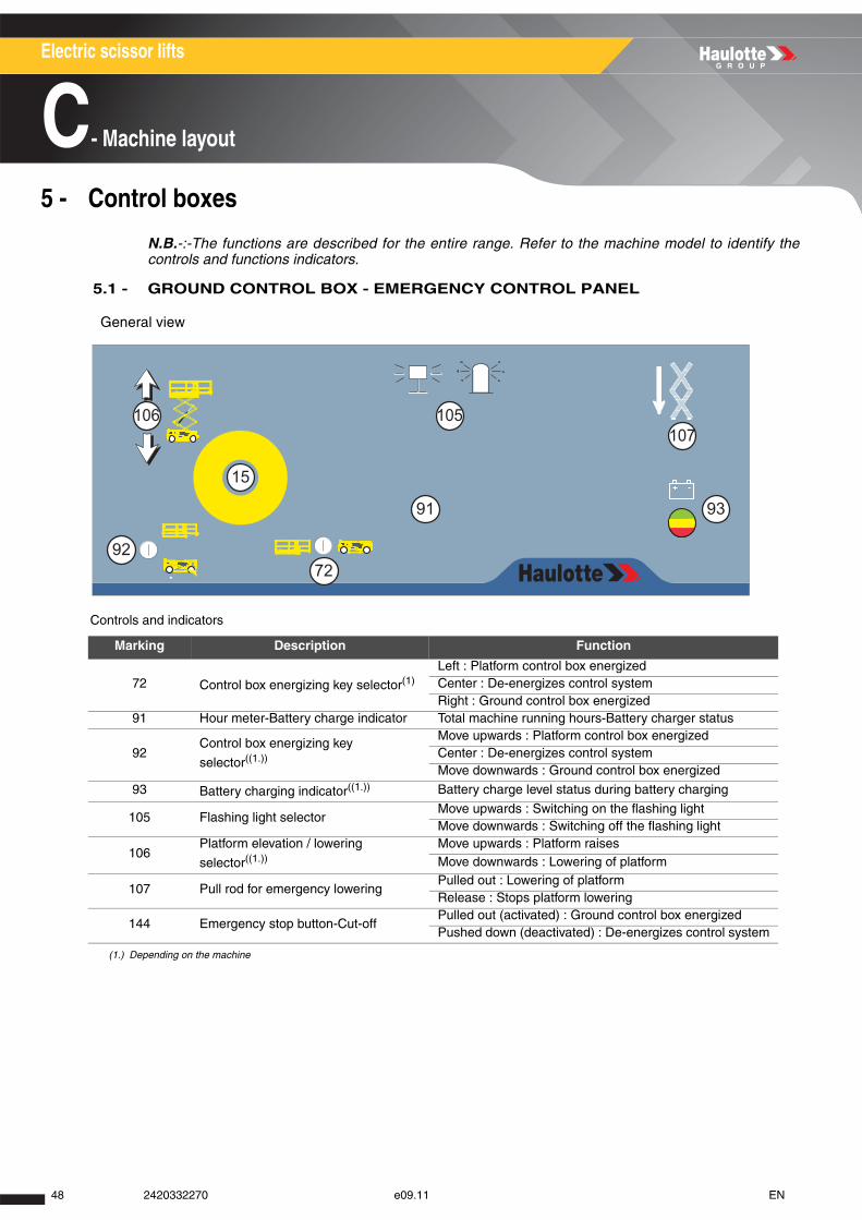
5 - Control boxes
N.B.-:-The functions are described for the entire range. Refer to the machine model to identify thecontrols and functions indicators.
5.1 - GROUND CONTROL BOX - EMERGENCY CONTROL PANEL
General view
Controls and indicators
Marking Description Function
72 Control box energizing key selector(1)
(1.) Depending on the machine
Left : Platform control box energizedCenter : De-energizes control systemRight : Ground control box energized
91 Hour meter-Battery charge indicator Total machine running hours-Battery charger status
92Control box energizing key
selector((1.))
Move upwards : Platform control box energizedCenter : De-energizes control systemMove downwards : Ground control box energized
93 Battery charging indicator((1.)) Battery charge level status during battery charging
105 Flashing light selectorMove upwards : Switching on the flashing lightMove downwards : Switching off the flashing light
106Platform elevation / lowering
selector((1.))Move upwards : Platform raisesMove downwards : Lowering of platform
107 Pull rod for emergency loweringPulled out : Lowering of platformRelease : Stops platform lowering
144 Emergency stop button-Cut-offPulled out (activated) : Ground control box energizedPushed down (deactivated) : De-energizes control system
15
7292
91 93
106 105107
48 2420332270 e09.11 EN
A
B
C
D
E
F
G
H
I
Electric scissor lifts
C- Machine layout
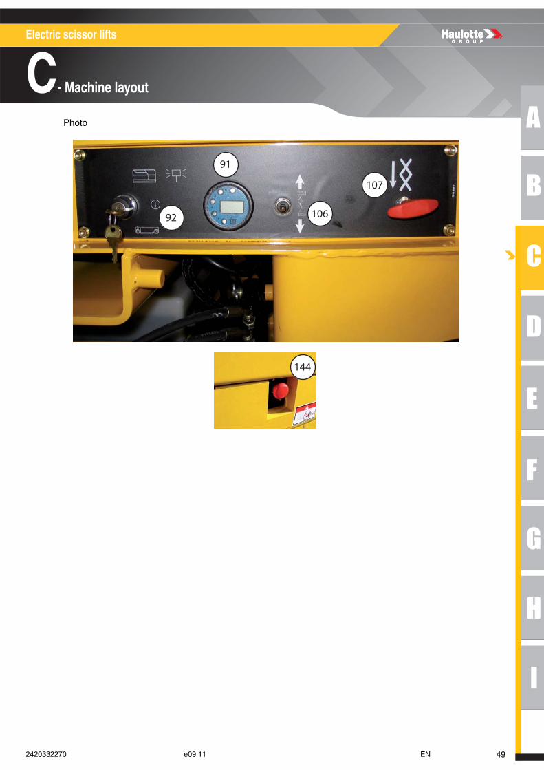
Photo
107
106
91
92
144
492420332270 e09.11 EN
Electric scissor lifts
C- Machine layout
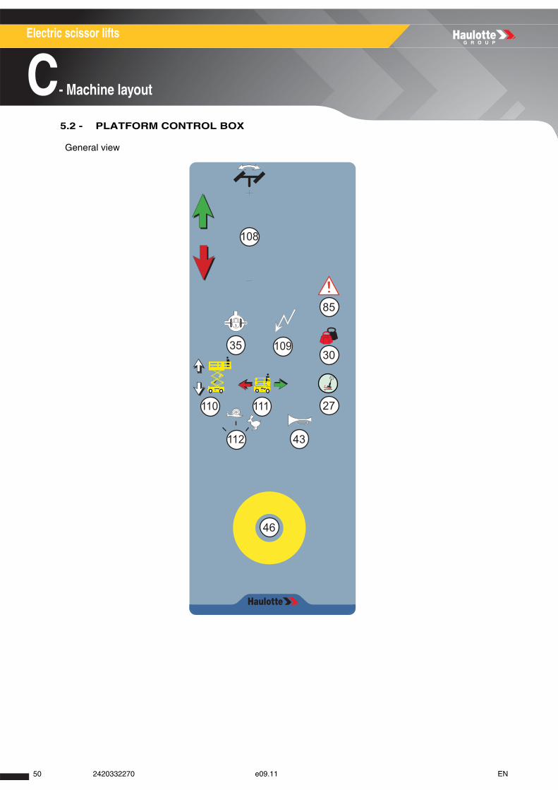
5.2 - PLATFORM CONTROL BOX
General view
108
109
110 111
112
35
43
46
27
30
85
50 2420332270 e09.11 EN
A
B
C
D
E
F
G
H
I
Electric scissor lifts
C- Machine layout
Controls and indicators
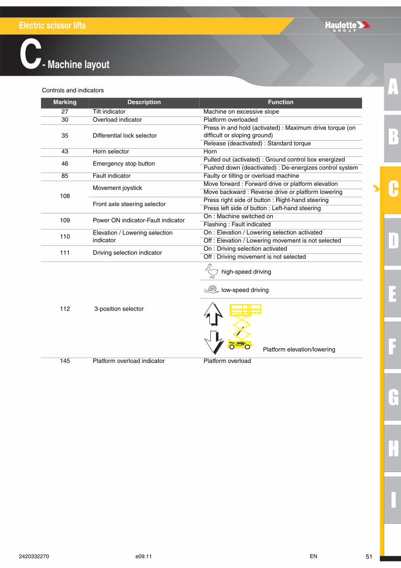
Marking Description Function
27 Tilt indicator Machine on excessive slope30 Overload indicator Platform overloaded
35 Differential lock selectorPress in and hold (activated) : Maximum drive torque (on difficult or sloping ground)Release (deactivated) : Standard torque
43 Horn selector Horn
46 Emergency stop buttonPulled out (activated) : Ground control box energizedPushed down (deactivated) : De-energizes control system
85 Fault indicator Faulty or tilting or overload machine
108Movement joystick
Move forward : Forward drive or platform elevationMove backward : Reverse drive or platform lowering
Front axle steering selectorPress right side of button : Right-hand steeringPress left side of button : Left-hand steering
109 Power ON indicator-Fault indicatorOn : Machine switched onFlashing : Fault indicated
110Elevation / Lowering selection indicator
On : Elevation / Lowering selection activatedOff : Elevation / Lowering movement is not selected
111 Driving selection indicatorOn : Driving selection activatedOff : Driving movement is not selected
112 3-position selector
high-speed driving
low-speed driving
Platform elevation/lowering
145 Platform overload indicator Platform overload
512420332270 e09.11 EN
Electric scissor lifts
C- Machine layout
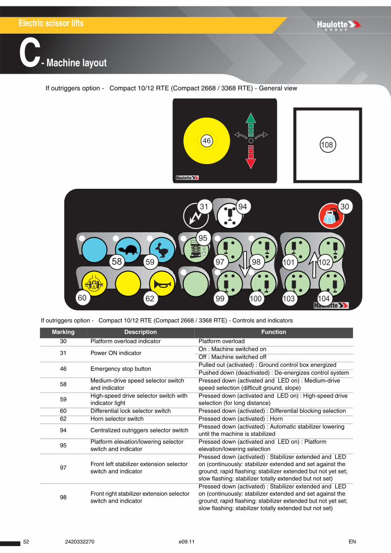
If outriggers option - Compact 10/12 RTE (Compact 2668 / 3368 RTE) - General view
If outriggers option - Compact 10/12 RTE (Compact 2668 / 3368 RTE) - Controls and indicators
Marking Description Function
30 Platform overload indicator Platform overload
31 Power ON indicatorOn : Machine switched onOff : Machine switched off
46 Emergency stop buttonPulled out (activated) : Ground control box energizedPushed down (deactivated) : De-energizes control system
58Medium-drive speed selector switch and indicator
Pressed down (activated and LED on) : Medium-drive speed selection (difficult ground, slope)
59High-speed drive selector switch with indicator light
Pressed down (activated and LED on) : High-speed drive selection (for long distance)
60 Differential lock selector switch Pressed down (activated) : Differential blocking selection62 Horn selector switch Pressed down (activated) : Horn
94 Centralized outriggers selector switchPressed down (activated) : Automatic stabilizer lowering until the machine is stabilized
95Platform elevation/lowering selector switch and indicator
Pressed down (activated and LED on) : Platform elevation/lowering selection
97Front left stabilizer extension selector switch and indicator
Pressed down (activated) : Stabilizer extended and LED on (continuously: stabilizer extended and set against the ground; rapid flashing: stabilizer extended but not yet set; slow flashing: stabilizer totally extended but not set)
98Front right stabilizer extension selector switch and indicator
Pressed down (activated) : Stabilizer extended and LED on (continuously: stabilizer extended and set against the ground; rapid flashing: stabilizer extended but not yet set; slow flashing: stabilizer totally extended but not set)
60
58 59
95
62 99
97 98
100 103
101 102
104
108
31 94 30
46
52 2420332270 e09.11 EN
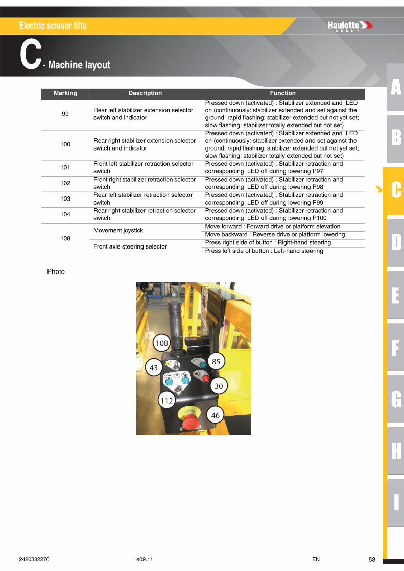
A
B
C
D
E
F
G
H
I
Electric scissor lifts
C- Machine layout
Photo
99Rear left stabilizer extension selector switch and indicator
Pressed down (activated) : Stabilizer extended and LED on (continuously: stabilizer extended and set against the ground; rapid flashing: stabilizer extended but not yet set; slow flashing: stabilizer totally extended but not set)
100Rear right stabilizer extension selector switch and indicator
Pressed down (activated) : Stabilizer extended and LED on (continuously: stabilizer extended and set against the ground; rapid flashing: stabilizer extended but not yet set; slow flashing: stabilizer totally extended but not set)
101Front left stabilizer retraction selector switch
Pressed down (activated) : Stabilizer retraction and corresponding LED off during lowering P97
102Front right stabilizer retraction selector switch
Pressed down (activated) : Stabilizer retraction and corresponding LED off during lowering P98
103Rear left stabilizer retraction selector switch
Pressed down (activated) : Stabilizer retraction and corresponding LED off during lowering P99
104Rear right stabilizer retraction selector switch
Pressed down (activated) : Stabilizer retraction and corresponding LED off during lowering P100
108Movement joystick
Move forward : Forward drive or platform elevationMove backward : Reverse drive or platform lowering
Front axle steering selectorPress right side of button : Right-hand steeringPress left side of button : Left-hand steering
Marking Description Function
108
43
112
85
30
46
532420332270 e09.11 EN

Electric scissor lifts
C- Machine layout
54 2420332270 e09.11 EN
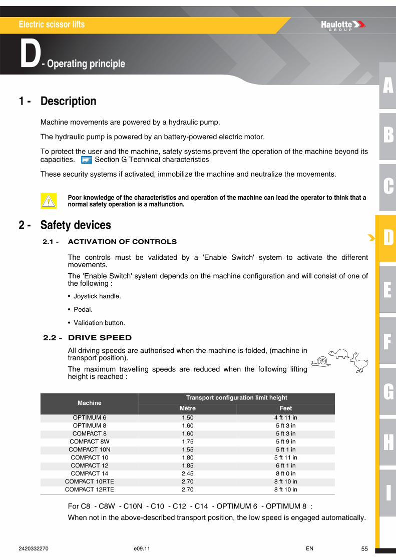
A
B
C
D
E
F
G
H
I
Electric scissor lifts
D- Operating principle
Operating principle1 - Description
Machine movements are powered by a hydraulic pump.
The hydraulic pump is powered by an battery-powered electric motor.
To protect the user and the machine, safety systems prevent the operation of the machine beyond itscapacities. Section G Technical characteristics
These security systems if activated, immobilize the machine and neutralize the movements.
2 - Safety devices 2.1 - ACTIVATION OF CONTROLS
The controls must be validated by a 'Enable Switch' system to activate the differentmovements.
The 'Enable Switch' system depends on the machine configuration and will consist of one ofthe following :
• Joystick handle.
• Pedal.
• Validation button.
2.2 - DRIVE SPEED
All driving speeds are authorised when the machine is folded, (machine intransport position).
The maximum travelling speeds are reduced when the following liftingheight is reached :
For C8 - C8W - C10N - C10 - C12 - C14 - OPTIMUM 6 - OPTIMUM 8 :
When not in the above-described transport position, the low speed is engaged automatically.
Poor knowledge of the characteristics and operation of the machine can lead the operator to think that anormal safety operation is a malfunction.
MachineTransport configuration limit height
Mètre Feet
OPTIMUM 6 1,50 4 ft 11 inOPTIMUM 8 1,60 5 ft 3 inCOMPACT 8 1,60 5 ft 3 in
COMPACT 8W 1,75 5 ft 9 inCOMPACT 10N 1,55 5 ft 1 inCOMPACT 10 1,80 5 ft 11 inCOMPACT 12 1,85 6 ft 1 inCOMPACT 14 2,45 8 ft 0 in
COMPACT 10RTE 2,70 8 ft 10 inCOMPACT 12RTE 2,70 8 ft 10 in
552420332270 e09.11 EN
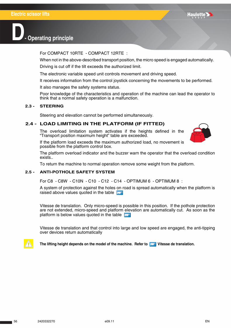
Electric scissor lifts
D- Operating principle
For COMPACT 10RTE - COMPACT 12RTE :
When not in the above-described transport position, the micro speed is engaged automatically.
Driving is cut off if the tilt exceeds the authorized limit.
The electronic variable speed unit controls movement and driving speed.
It receives information from the control joystick concerning the movements to be performed.
It also manages the safety systems status.
Poor knowledge of the characteristics and operation of the machine can lead the operator tothink that a normal safety operation is a malfunction.
2.3 - STEERING
Steering and elevation cannot be performed simultaneously.
2.4 - LOAD LIMITING IN THE PLATFORM (IF FITTED)
The overload limitation system activates if the heights defined in the“Transport position maximum height” table are exceeded.
If the platform load exceeds the maximum authorized load, no movement ispossible from the platform control box.
The platform overload indicator and the buzzer warn the operator that the overload conditionexists..
To return the machine to normal operation remove some weight from the platform.
2.5 - ANTI-POTHOLE SAFETY SYSTEM
For C8 - C8W - C10N - C10 - C12 - C14 - OPTIMUM 6 - OPTIMUM 8 :
A system of protection against the holes on road is spread automatically when the platform israised above values quoted in the table
Vitesse de translation. Only micro-speed is possible in this position. If the pothole protectionare not extended, micro-speed and platform elevation are automatically cut. As soon as theplatform is below values quoted in the table
Vitesse de translation and that control into large and low speed are engaged, the anti-tippingover devices return automatically
The lifting height depends on the model of the machine. Refer to Vitesse de translation.
56 2420332270 e09.11 EN
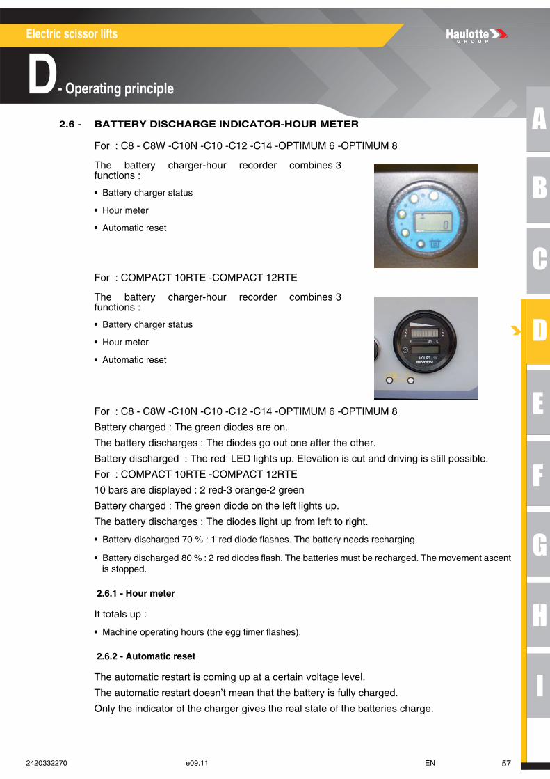
A
B
C
D
E
F
G
H
I
Electric scissor lifts
D- Operating principle
2.6 - BATTERY DISCHARGE INDICATOR-HOUR METER
For : C8 - C8W -C10N -C10 -C12 -C14 -OPTIMUM 6 -OPTIMUM 8
For : COMPACT 10RTE -COMPACT 12RTE
For : C8 - C8W -C10N -C10 -C12 -C14 -OPTIMUM 6 -OPTIMUM 8
Battery charged : The green diodes are on.
The battery discharges : The diodes go out one after the other.
Battery discharged : The red LED lights up. Elevation is cut and driving is still possible.
For : COMPACT 10RTE -COMPACT 12RTE
10 bars are displayed : 2 red-3 orange-2 green
Battery charged : The green diode on the left lights up.
The battery discharges : The diodes light up from left to right.
• Battery discharged 70 % : 1 red diode flashes. The battery needs recharging.
• Battery discharged 80 % : 2 red diodes flash. The batteries must be recharged. The movement ascentis stopped.
2.6.1 - Hour meter
It totals up :
• Machine operating hours (the egg timer flashes).
2.6.2 - Automatic reset
The automatic restart is coming up at a certain voltage level.
The automatic restart doesn’t mean that the battery is fully charged.
Only the indicator of the charger gives the real state of the batteries charge.
The battery charger-hour recorder combines 3functions :
• Battery charger status
• Hour meter
• Automatic reset
The battery charger-hour recorder combines 3functions :
• Battery charger status
• Hour meter
• Automatic reset
572420332270 e09.11 EN
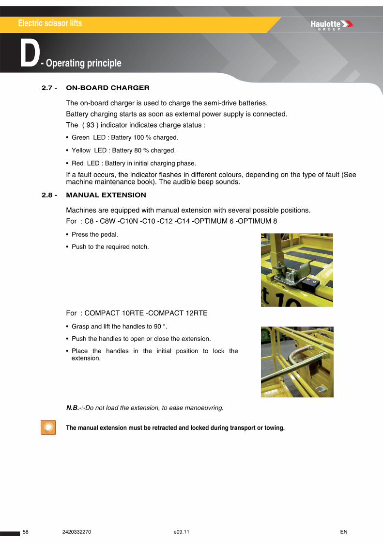
Electric scissor lifts
D- Operating principle
2.7 - ON-BOARD CHARGER
The on-board charger is used to charge the semi-drive batteries.
Battery charging starts as soon as external power supply is connected.
The ( 93 ) indicator indicates charge status :
• Green LED : Battery 100 % charged.
• Yellow LED : Battery 80 % charged.
• Red LED : Battery in initial charging phase.
If a fault occurs, the indicator flashes in different colours, depending on the type of fault (Seemachine maintenance book). The audible beep sounds.
2.8 - MANUAL EXTENSION
Machines are equipped with manual extension with several possible positions.
For : C8 - C8W -C10N -C10 -C12 -C14 -OPTIMUM 6 -OPTIMUM 8
For : COMPACT 10RTE -COMPACT 12RTE
N.B.-:-Do not load the extension, to ease manoeuvring.
• Press the pedal.
• Push to the required notch.
• Grasp and lift the handles to 90 °.
• Push the handles to open or close the extension.
• Place the handles in the initial position to lock theextension.
The manual extension must be retracted and locked during transport or towing.
58 2420332270 e09.11 EN
A
B
C
D
E
F
G
H
I
Electric scissor lifts
E- Driving
Driving1 - Recommendations
The manager of the company responsible for the commissioning of the machine must ensure that themachine is fit for the work it is to perform. i.e. that the machine is suitable to carry out the work incomplete safety in compliance with this Operator Manual. All managers who are responsible forpersons operating the machine, must be familiar with the regulations currently applicable in the countryof use and ensure that they are adhered to.
N.B.-:-The machine reaches optimum performance (speed of movement, load capacity) when thetemperature of the oil in the hydraulic circuit is greater than 10°C. After a prolonged period of disuse ata lower temperature, lifting and lowering the platform several times without any load and performing afew translation movements is enough to restore the machine's nominal performances.
2 - Checks before use
Each day and before the beginning of a new work period and on each change of operator, the machinemust be subjected to a visual inspection and a complete functional test.
Any repairs required must be performed before the machine is used, its correct operation depends on it.
2.1 - VISUAL INSPECTIONS
2.1.1 - General mechanical functions
For all the following checks, ensure that the machine is switched off.
Check the following points :
• The presence of the identification plate, labels and operator manual :
• Their state of cleanliness and visibility.
• Clean or replace if necessary.
• Visual state of the machine :
• Absence of leaks (battery acid, hydraulic oil, etc.). Absence of foreign objects on all surfaces. Call thestaff in charge of the maintenance if necessary.
• No missing or loose parts (bolts, nuts, connectors, cables, etc.). Refer to the "tightening torques" tablequoted in the Maintenance Book.
• Absence of cracks, broken parts, damaged paint. No deformations or other anomalies on thestructure’s parts.
Before using the machine, read the previous chapters in this manual. Ensure that you have understoodthe following points :
• Safety precautions.
• Operator's responsibilities.
• Presentation and the operating principle of the machine.
Find all the function indicators and controls in Section C 5 - Control boxes
592420332270 e09.11 EN
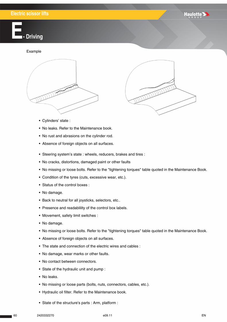
Electric scissor lifts
E- Driving
Example
• Cylinders’ state :
• No leaks. Refer to the Maintenance book.
• No rust and abrasions on the cylinder rod.
• Absence of foreign objects on all surfaces.
• Steering system’s state : wheels, reducers, brakes and tires :
• No cracks, distortions, damaged paint or other faults
• No missing or loose bolts. Refer to the "tightening torques" table quoted in the Maintenance Book.
• Condition of the tyres (cuts, excessive wear, etc.).
• Status of the control boxes :
• No damage.
• Back to neutral for all joysticks, selectors, etc..
• Presence and readablility of the control box labels.
• Movement, safety limit switches :
• No damage.
• No missing or loose bolts. Refer to the "tightening torques" table quoted in the Maintenance Book.
• Absence of foreign objects on all surfaces.
• The state and connection of the electric wires and cables :
• No damage, wear marks or other faults.
• No contact between connectors.
• State of the hydraulic unit and pump :
• No leaks.
• No missing or loose parts (bolts, nuts, connectors, cables, etc.).
• Hydraulic oil filter. Refer to the Maintenance book.
• State of the structure's parts : Arm, platform :
60 2420332270 e09.11 EN
A
B
C
D
E
F
G
H
I
Electric scissor lifts
E- Driving
• No cracks, damaged paint.
• No distortion in metal components or visible damage.
• No foreign objects between arms.
• Guardrails are present and locked in place.
• Presence and check the original position of the platform control box sliding bar.
• State of the tanks :
• No leaks.
• No missing or loose parts (bolts, nuts, connectors, cables, etc.). Top up the oil level, if necessary(Machine in transport position).
2.1.2 - Environment
Section A -Safety precautions.
Check the following points :
• Wind speed ( Section G 1-Main characteristics).
• The permissible ground pressure and loading on the machine supporting surface ( Section G 1-Main characteristics).
• The maximum permissible load in the platform ( Section G 1-Main characteristics).
• The maximum permissible lateral force allowed at the platform ( Section G 1-Maincharacteristics).
2.2 - FUNCTIONAL TESTS
2.2.1 - Safety features
Features to be tested :
• Operation of the upper and lower emergency stop buttons.
• Operation of the tilt sensor.
• Visual and audible alarms.
• Platform load management system (Where fitted).
For functional test procedures refer to ( Section E 3.1-Test procedure).
612420332270 e09.11 EN
Electric scissor lifts
E- Driving
2.2.2 - Ground control box controls (emergency station)
Refer to the corresponding operations to test the controls in the order mentioned( Section E 3.2-Operation from ground position).
2.2.3 - Platform control box controls (driving station)
Refer to the corresponding operations to test the controls in the order mentioned( Section E 3.3-Operations from the platform).
2.3 - PERIODICAL CHECKS
The machine must be inspected on a regular basis at intervals in accordance with therequirements set forth in the Country of use but no less than once per year. The purpose ofthe inspection is to detect any defect which could lead to an accident during routine use of themachine.
These inspections must be carried out by a competent company or person whose selection isunder the responsibility of the manager (Company employee or other).
The inspection results must be recorded in the safety register or machine log book controlledand overseen by the company manager. This register or machine log book and the list ofcompetent repair persons must be made available to the Government Work Inspector andcompany safety commitee at all times.
N.B.-:- Section H Intervention register
2.4 - REPAIRS AND ADJUSTMENTS
Extensive repairs, interventions or adjustments on the safety systems or elements must beperformed by a HAULOTTE Services® employee or a HAULOTTE Services®-approvedemployee with HAULOTTE Services® training, using original spare parts only.
HAULOTTE Services® technicians are specially trained to carry out extensive repairs,interventions or adjustments on the safety systems or elements of HAULOTTE® machines,and carry genuine HAULOTTE spare parts and tools as required, and also provide fullydocumented reports on all work completed..
Step Control
1 Control box energizing key selector( 72 ) or (92)(Depending on the machine)2 Movements : Platform elevation/lowering( 106 )3 Flashing light selector( 105 )
Step Control
1 Control box energizing key selector 72 or 92 (Depending on the machine)2 Energizes control system 462 Steering ( 108 ), driving ( 112 ) and indicator ( 111 ) selector3 Driving ( 108 ) and steering ( 112 ) and 1114 Drive and steering ( 108 ) movements5 selector : Platform elevation/lowering ( 110 ) and ( 112 ) or ( 95 )5 Movement : Platform elevation/lowering (108) or (95) 6 Horn selector 43
62 2420332270 e09.11 EN
A
B
C
D
E
F
G
H
I
Electric scissor lifts
E- Driving
HAULOTTE Services® will not take responsibility for any consequential outcomes resultingfrom inferior services/repairs carried out by others.
HAULOTTE advises you that NO modifications carried out without the written permissionof HAULOTTE® will void the HAULOTTE warranty..
2.5 - INSPECTION / TESTING REQUIREMENTS
Intervention to be made after :
• Extensive dismantling and reassembly.
• Repairs involving the machine's essential components.
• Any accident causing stress to the machine.
Perform a fitness for function inspection, a condition inspection and static and dynamic tests(Consult the After-Sales Service HAULOTTE Services®).
3 - Operation
N.B.-:-The functions are described for the entire range. Refer to the machine model to identify thecontrols and functions indicators.
3.1 - TEST PROCEDURE
3.1.1 - Emergency stop switch- button function (cut out)
Ground control box emergency stop button
Platform control box emergency stop button
Find all the function indicators and controls in Section C 5 - Control boxes
Step Action
1 Pull the emergency stop switch- buttons (cut-off) 144, 462 Switch the machine on 72 or 92(Depending on the machine).
3Turn the ( 72 ) or ( 92 ) control box activation keyed selector switch to the right to energize the ground control box(Depending on the machine). The indicators light up.
4 Push the emergency stop switch- push button (cut-off) 144. The indicators go out.
Step Action
1 Pull the emergency stop switch- buttons (cut-off) 144, 462 Switch the machine on 72 or 92(Depending on the machine).
3Turn the ( 72 ) or ( 92 ) control box activation selection key to the left to activate the platform control box(Depending on the machine). The indicators light up.
4 Push the emergency stop switch- push button (cut-off) 46. The indicators go out.
632420332270 e09.11 EN
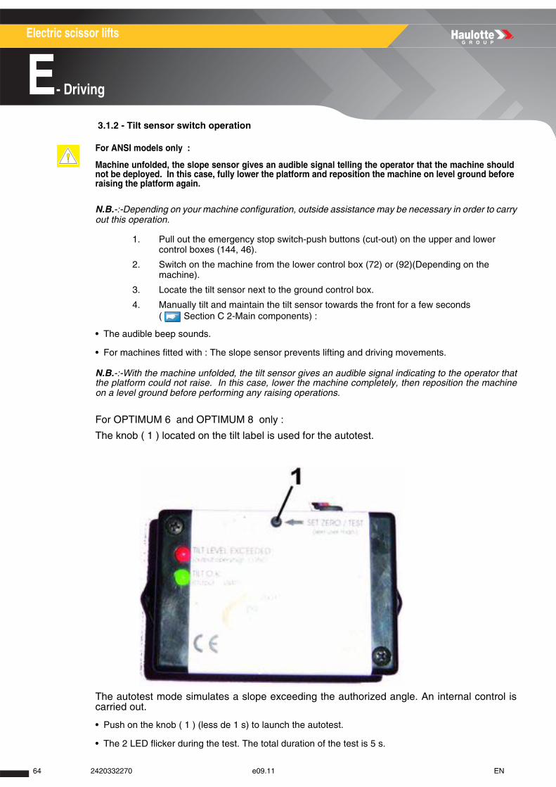
Electric scissor lifts
E- Driving
3.1.2 - Tilt sensor switch operation
N.B.-:-Depending on your machine configuration, outside assistance may be necessary in order to carryout this operation.
1. Pull out the emergency stop switch-push buttons (cut-out) on the upper and lower control boxes (144, 46).
2. Switch on the machine from the lower control box (72) or (92)(Depending on the machine).
3. Locate the tilt sensor next to the ground control box.
4. Manually tilt and maintain the tilt sensor towards the front for a few seconds ( Section C 2-Main components) :
• The audible beep sounds.
• For machines fitted with : The slope sensor prevents lifting and driving movements.
N.B.-:-With the machine unfolded, the tilt sensor gives an audible signal indicating to the operator thatthe platform could not raise. In this case, lower the machine completely, then reposition the machineon a level ground before performing any raising operations.
For OPTIMUM 6 and OPTIMUM 8 only :
The knob ( 1 ) located on the tilt label is used for the autotest.
The autotest mode simulates a slope exceeding the authorized angle. An internal control iscarried out.
• Push on the knob ( 1 ) (less de 1 s) to launch the autotest.
• The 2 LED flicker during the test. The total duration of the test is 5 s.
For ANSI models only :
Machine unfolded, the slope sensor gives an audible signal telling the operator that the machine shouldnot be deployed. In this case, fully lower the platform and reposition the machine on level ground beforeraising the platform again.
64 2420332270 e09.11 EN
A
B
C
D
E
F
G
H
I
Electric scissor lifts
E- Driving
Messages delivered by the tilt detector
N.B.-:-Once the test carried out, return under normal operation.
3.1.3 - Visual and sound alarms
1. Pull the emergency stop switch- buttons (cut-off) (144, 46).
2. Switch the machine on (72) or (92)(Depending on the machine). All of the ground control box indicators light up and a sound signal (beep) is emitted.
3.1.4 - Weighing system
1. Pull the emergency stop switch- buttons (cut-off) (144, 46).
2. Switch the machine on (72) or (92)(Depending on the machine). The platform control box overload indicator ( 30 ) warns the user.
3.1.5 - 8 m(26 ft3 in) drive cut-off (Floor height)
3.2 - OPERATION FROM GROUND POSITION
3.2.1 - Machine start-up
1. Pull the emergency stop button 144.
2. Switch the machine on 72 or 92(Depending on the machine).
3. Turn the key on the control box activation selector switch ( 72 ) to the right to energize the ground control box.
indicator Status
Description
Lit green LED Machine in authorized angular positionBlinkling green
LEDMachine exceeding the angular limit within the authorized time
LED red lit Machine exceeding the authorized angular limitGreen LED and
reds litFault detector
Green LED and red twinkling
Detector in autotest
For C10RTE / C12RTE machine only : 1. Always ensure that the chassis is never driven any closer than 2 m(6 ft7
in) m to holes, bumps, tilts, obstructions, debris and ground coverings that may hide holes and other dangers.
2. From the upper control panel, set the gear selector ( 112 ) to microspeed position.
3. Raise the platform at 8 m(26 ft3 in) minimum (Floor height)
4. Push the movement joystick ( 108 ) forwards to move the machine forwards
5. No travel movement has to be performed from the upper control panel.
Ground control box is an auxiliary to be used only in case of emergency.
652420332270 e09.11 EN
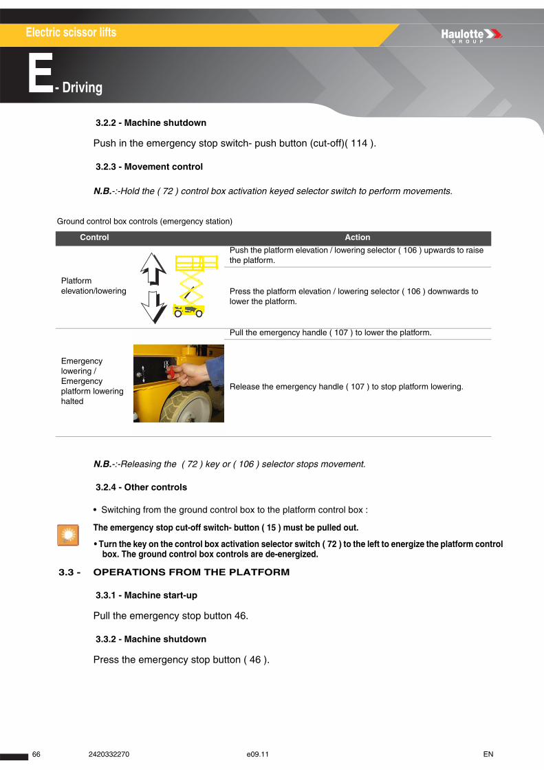
Electric scissor lifts
E- Driving
3.2.2 - Machine shutdown
Push in the emergency stop switch- push button (cut-off)( 114 ).
3.2.3 - Movement control
N.B.-:-Hold the ( 72 ) control box activation keyed selector switch to perform movements.
Ground control box controls (emergency station)
N.B.-:-Releasing the ( 72 ) key or ( 106 ) selector stops movement.
3.2.4 - Other controls
• Switching from the ground control box to the platform control box :
3.3 - OPERATIONS FROM THE PLATFORM
3.3.1 - Machine start-up
Pull the emergency stop button 46.
3.3.2 - Machine shutdown
Press the emergency stop button ( 46 ).
Control Action
Platform elevation/lowering
Push the platform elevation / lowering selector ( 106 ) upwards to raise the platform.
Press the platform elevation / lowering selector ( 106 ) downwards to lower the platform.
Emergency lowering / Emergency platform lowering halted
Pull the emergency handle ( 107 ) to lower the platform.
Release the emergency handle ( 107 ) to stop platform lowering.
The emergency stop cut-off switch- button ( 15 ) must be pulled out.
• Turn the key on the control box activation selector switch ( 72 ) to the left to energize the platform controlbox. The ground control box controls are de-energized.
66 2420332270 e09.11 EN
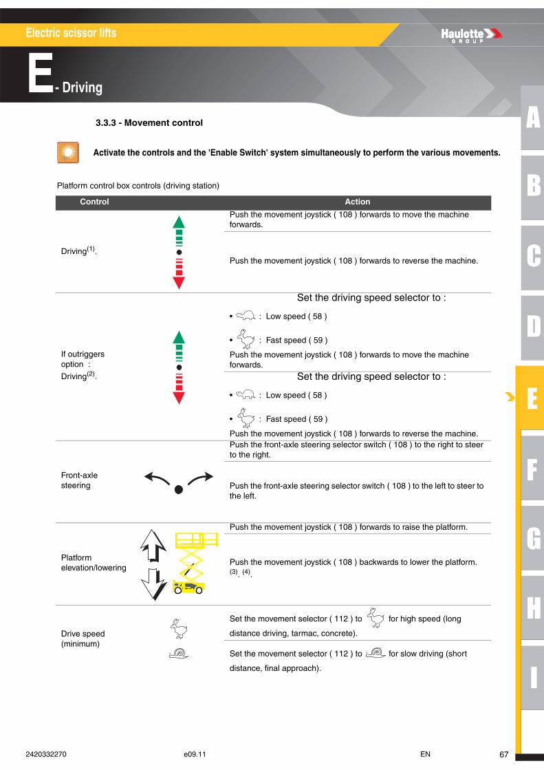
A
B
C
D
E
F
G
H
I
Electric scissor lifts
E- Driving
3.3.3 - Movement control
Platform control box controls (driving station)
Activate the controls and the 'Enable Switch' system simultaneously to perform the various movements.
Control Action
Driving(1).
Push the movement joystick ( 108 ) forwards to move the machine forwards.
Push the movement joystick ( 108 ) forwards to reverse the machine.
If outriggers option :
Driving(2).
Set the driving speed selector to :
• : Low speed ( 58 )
• : Fast speed ( 59 )
Push the movement joystick ( 108 ) forwards to move the machine forwards.
Set the driving speed selector to :
• : Low speed ( 58 )
• : Fast speed ( 59 )
Push the movement joystick ( 108 ) forwards to reverse the machine.
Front-axle steering
Push the front-axle steering selector switch ( 108 ) to the right to steer to the right.
Push the front-axle steering selector switch ( 108 ) to the left to steer to the left.
Platform elevation/lowering
Push the movement joystick ( 108 ) forwards to raise the platform.
Push the movement joystick ( 108 ) backwards to lower the platform. (3). (4).
Drive speed (minimum)
Set the movement selector ( 112 ) to for high speed (long
distance driving, tarmac, concrete).
Set the movement selector ( 112 ) to for slow driving (short
distance, final approach).
672420332270 e09.11 EN
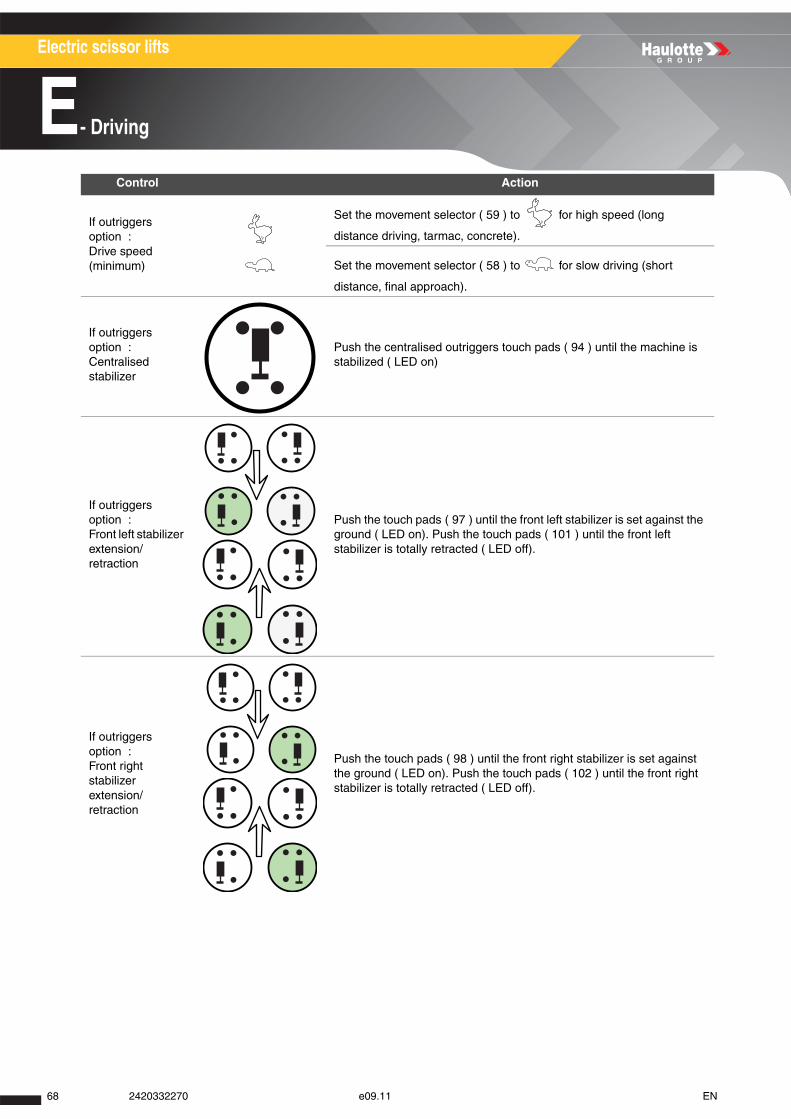
Electric scissor lifts
E- Driving
If outriggers option : Drive speed (minimum)
Set the movement selector ( 59 ) to for high speed (long
distance driving, tarmac, concrete).
Set the movement selector ( 58 ) to for slow driving (short
distance, final approach).
If outriggers option : Centralised stabilizer
Push the centralised outriggers touch pads ( 94 ) until the machine is stabilized ( LED on)
If outriggers option : Front left stabilizer extension/retraction
Push the touch pads ( 97 ) until the front left stabilizer is set against the ground ( LED on). Push the touch pads ( 101 ) until the front left stabilizer is totally retracted ( LED off).
If outriggers option : Front right stabilizer extension/retraction
Push the touch pads ( 98 ) until the front right stabilizer is set against the ground ( LED on). Push the touch pads ( 102 ) until the front right stabilizer is totally retracted ( LED off).
Control Action
68 2420332270 e09.11 EN
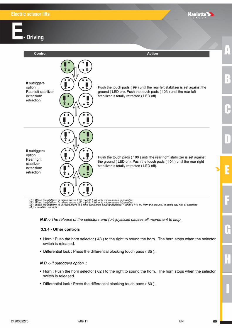
A
B
C
D
E
F
G
H
I
Electric scissor lifts
E- Driving
N.B.-:-The release of the selectors and (or) joysticks causes all movement to stop.
3.3.4 - Other controls
• Horn : Push the horn selector ( 43 ) to the right to sound the horn. The horn stops when the selectorswitch is released.
• Differential lock : Press the differential blocking touch pads ( 35 ).
N.B.-:-If outriggers option :
• Horn : Push the horn selector ( 62 ) to the right to sound the horn. The horn stops when the selectorswitch is released.
• Differential lock : Press the differential blocking touch pads ( 60 ).
If outriggers option : Rear left stabilizer extension/retraction
Push the touch pads ( 99 ) until the rear left stabilizer is set against the ground ( LED on). Push the touch pads ( 103 ) until the rear left stabilizer is totally retracted ( LED off).
If outriggers option : Rear right stabilizer extension/retraction
Push the touch pads ( 100 ) until the rear right stabilizer is set against the ground ( LED on). Push the touch pads ( 104 ) until the rear right stabilizer is totally retracted ( LED off).
(1.) When the platform is raised above 1,50 m(4 ft11 in), only micro-speed is possible(2.) When the platform is raised above 1,50 m(4 ft11 in), only micro-speed is possible(3.) When the platform is lowered,there is a time out lasting several seconds 1,50 m(4 ft11 in) from the ground, to avoid any risk of crushing(4.) The alarm sounds
Control Action
692420332270 e09.11 EN

Electric scissor lifts
E- Driving
70 2420332270 e09.11 EN
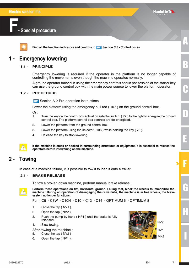
A
B
C
D
E
F
G
H
I
Electric scissor lifts
F- Special procedure
Special procedure
1 - Emergency lowering 1.1 - PRINCIPLE
Emergency lowering is required if the operator in the platform is no longer capable ofcontrolling the movements even though the machine operates normally.
A ground operator trained in using the emergency controls and in possession of the starter keycan use the ground control box with the main power source to lower the platform operator.
1.2 - PROCEDURE
Section A 2-Pre-operation instructions
Lower the platform using the emergency pull rod ( 107 ) on the ground control box.
Or : 1. Turn the key on the control box activation selector switch ( 72 ) to the right to energize the ground
control box. The platform control box controls are de-energized.
2. Lower the platform from the ground control box.
3. Lower the platform using the selector ( 106 ) while holding the key ( 72 ).
4. Release the key to stop lowering.
2 - Towing
In case of a machine failure, it is possible to tow it to load it onto a trailer.
2.1 - BRAKE RELEASE
To tow a broken-down machine, perform manual brake release.
For : C8 - C8W - C10N - C10 - C12 - C14 - OPTIMUM 6 - OPTIMUM 8
Find all the function indicators and controls in Section C 5 - Control boxes
If the machine is stuck or hooked in surrounding structures or equipment, it is essential to release theoperators before intervening on the machine.
Perform these operations on flat, horizontal ground. Failing that, block the wheels to immobilize themachine. During an operation of disengaging the drive hubs, the machine is in free wheels, the brakesystem no longer functions.
1. Close the tap ( NV1 ).
2. Open the tap ( NV2 ).
3. Push the pump by hand ( HP1 ) until the brake is fullyreleased.
4. Slow towing.
After towing the machine : 5. Close the tap ( NV2 )
6. Open the tap ( NV1 ).
NV2
NV1
MK4
712420332270 e09.11 EN
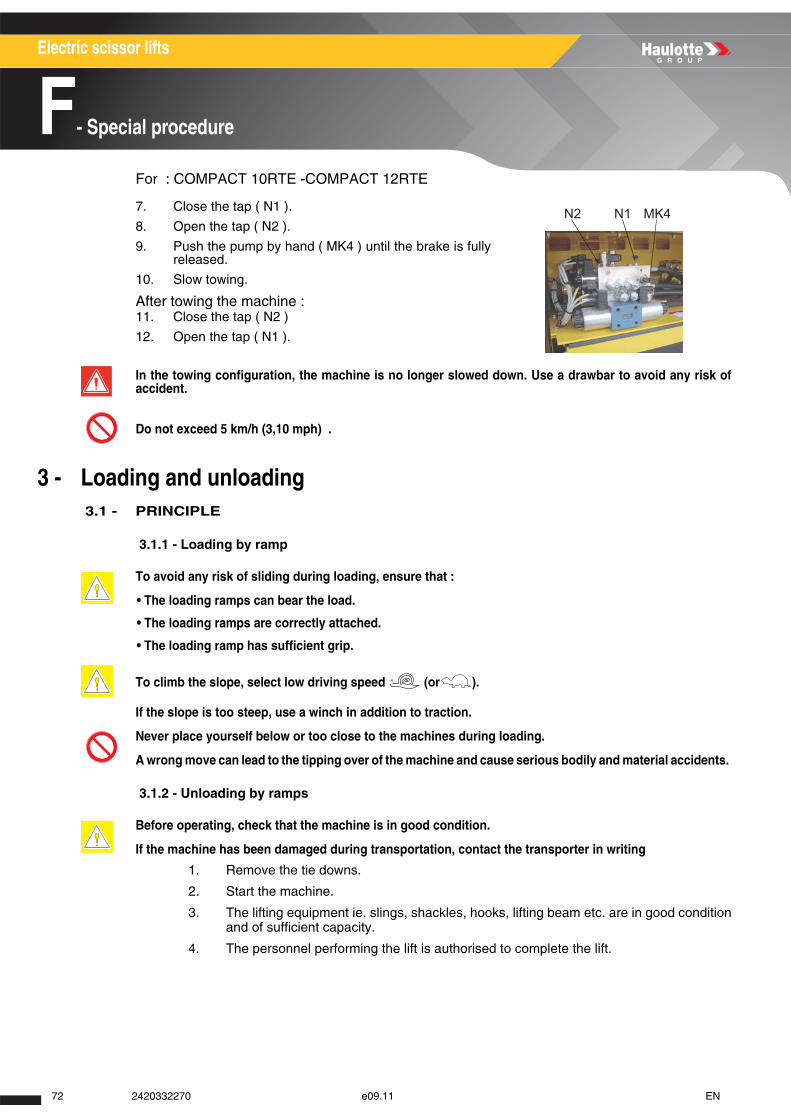
Electric scissor lifts
F- Special procedure
For : COMPACT 10RTE -COMPACT 12RTE
3 - Loading and unloading 3.1 - PRINCIPLE
3.1.1 - Loading by ramp
3.1.2 - Unloading by ramps
1. Remove the tie downs.
2. Start the machine.
3. The lifting equipment ie. slings, shackles, hooks, lifting beam etc. are in good condition and of sufficient capacity.
4. The personnel performing the lift is authorised to complete the lift.
7. Close the tap ( N1 ).
8. Open the tap ( N2 ).
9. Push the pump by hand ( MK4 ) until the brake is fullyreleased.
10. Slow towing.
After towing the machine : 11. Close the tap ( N2 )
12. Open the tap ( N1 ).
In the towing configuration, the machine is no longer slowed down. Use a drawbar to avoid any risk ofaccident.
Do not exceed 5 km/h (3,10 mph) .
To avoid any risk of sliding during loading, ensure that :
• The loading ramps can bear the load.
• The loading ramps are correctly attached.
• The loading ramp has sufficient grip.
To climb the slope, select low driving speed (or ).
If the slope is too steep, use a winch in addition to traction.
Never place yourself below or too close to the machines during loading.
A wrong move can lead to the tipping over of the machine and cause serious bodily and material accidents.
Before operating, check that the machine is in good condition.
If the machine has been damaged during transportation, contact the transporter in writing
N2 N1 MK4
72 2420332270 e09.11 EN
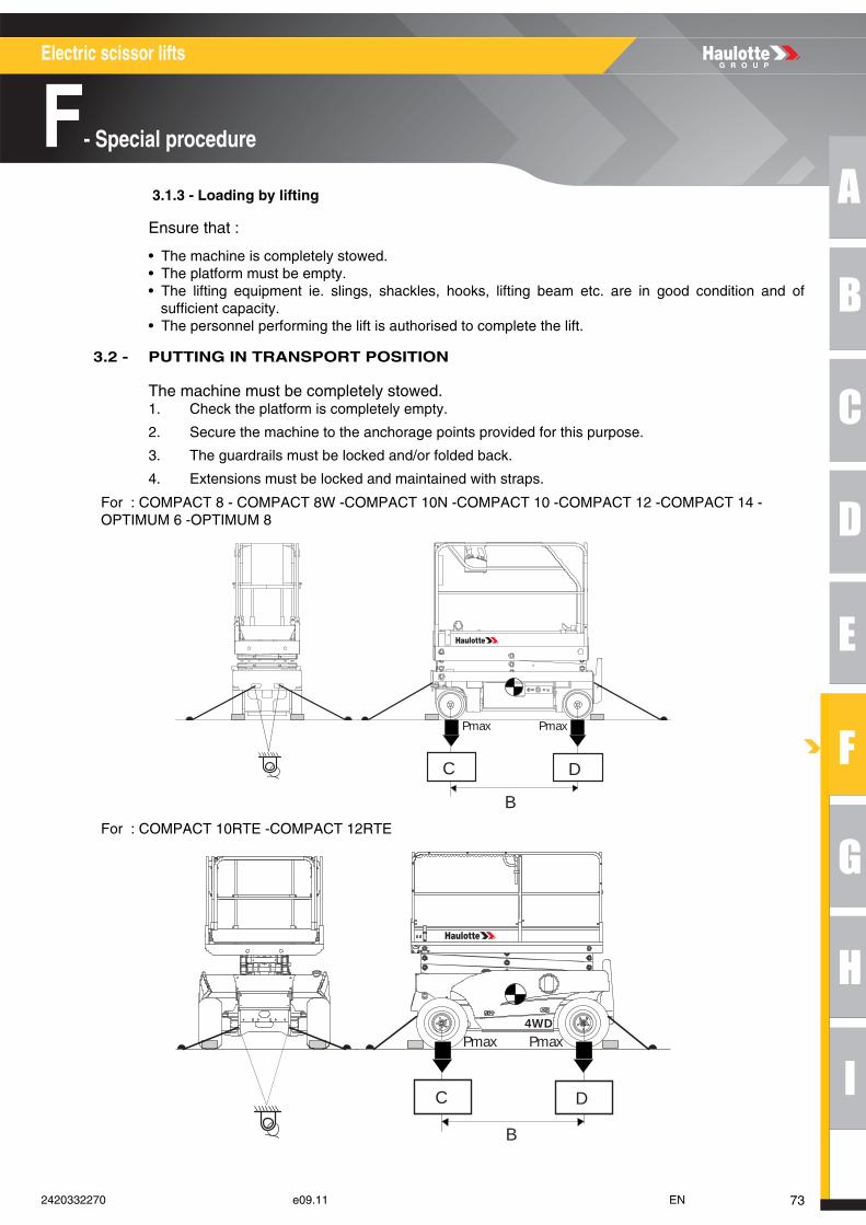
A
B
C
D
E
F
G
H
I
Electric scissor lifts
F- Special procedure
3.1.3 - Loading by lifting
Ensure that :
• The machine is completely stowed. • The platform must be empty. • The lifting equipment ie. slings, shackles, hooks, lifting beam etc. are in good condition and of
sufficient capacity. • The personnel performing the lift is authorised to complete the lift.
3.2 - PUTTING IN TRANSPORT POSITION
The machine must be completely stowed. 1. Check the platform is completely empty.
2. Secure the machine to the anchorage points provided for this purpose.
3. The guardrails must be locked and/or folded back.
4. Extensions must be locked and maintained with straps.
For : COMPACT 8 - COMPACT 8W -COMPACT 10N -COMPACT 10 -COMPACT 12 -COMPACT 14 -OPTIMUM 6 -OPTIMUM 8
For : COMPACT 10RTE -COMPACT 12RTE
B
C D
PmaxPmax
4WD
B
C D
PmaxPmax
732420332270 e09.11 EN

Electric scissor lifts
F- Special procedure
Loading characteristics
Loading characteristics
Loading characteristics
Loading characteristics
Loading characteristics
Marking Description C8 C8W
B Lateral distance between the wheels() 1,86 m(6 ft1 in) 1,86 m(6 ft1 in)
C Front wheel ground pressure() 13,2 daN/cm² (2,70 lbf/sq.ft)
17,3 daN/cm² (3,54 lbf/sq.ft)
D Rear wheel ground pressure() 13,2 daN/cm² (2,70 lbf/sq.ft)
17,3 daN/cm² (3,54 lbf/sq.ft)
Anchorage point
Marking Description C8 Single load (Option)
B Lateral distance between the wheels() 1,86 m(6 ft1 in)
C Front wheel ground pressure() 14,47 daN/cm² (2,96 lbf/sq.ft)
D Rear wheel ground pressure() 14,47 daN/cm² (2,96 lbf/sq.ft)
Anchorage point
Marking Description C10N C10
B Lateral distance between the wheels() 1,86 m(6 ft1 in) 1,86 m(6 ft1 in)
C Front wheel ground pressure() 15,96 daN/cm² (3,27 lbf/sq.ft)
17,7 daN/cm² (3,63 lbf/sq.ft)
D Rear wheel ground pressure() 15,96 daN/cm² (3,27 lbf/sq.ft)
17,7 daN/cm² (3,63 lbf/sq.ft)
Anchorage point
Marking Description C12 C14
B Lateral distance between the wheels() 1,86 m(6 ft1 in) 1,86 m(6 ft1 in)
C Front wheel ground pressure() 19,3 daN/cm² (3,95 lbf/sq.ft)
28,7 daN/cm² (5,88 lbf/sq.ft)
D Rear wheel ground pressure() 19,3 daN/cm² (3,95 lbf/sq.ft)
28,7 daN/cm² (5,88 lbf/sq.ft)
Anchorage point
Marking Description OPTIMUM 6 OPTIMUM 8
B Lateral distance between the wheels() 1,38 m(4 ft6 in) 1,38 m(4 ft6 in)
C Front wheel ground pressure() 14,9 daN/cm² (3,05 lbf/sq.ft)
17,8 daN/cm² (3,65 lbf/sq.ft)
D Rear wheel ground pressure() 14,9 daN/cm² (3,05 lbf/sq.ft)
17,8 daN/cm² (3,65 lbf/sq.ft)
Anchorage point
74 2420332270 e09.11 EN
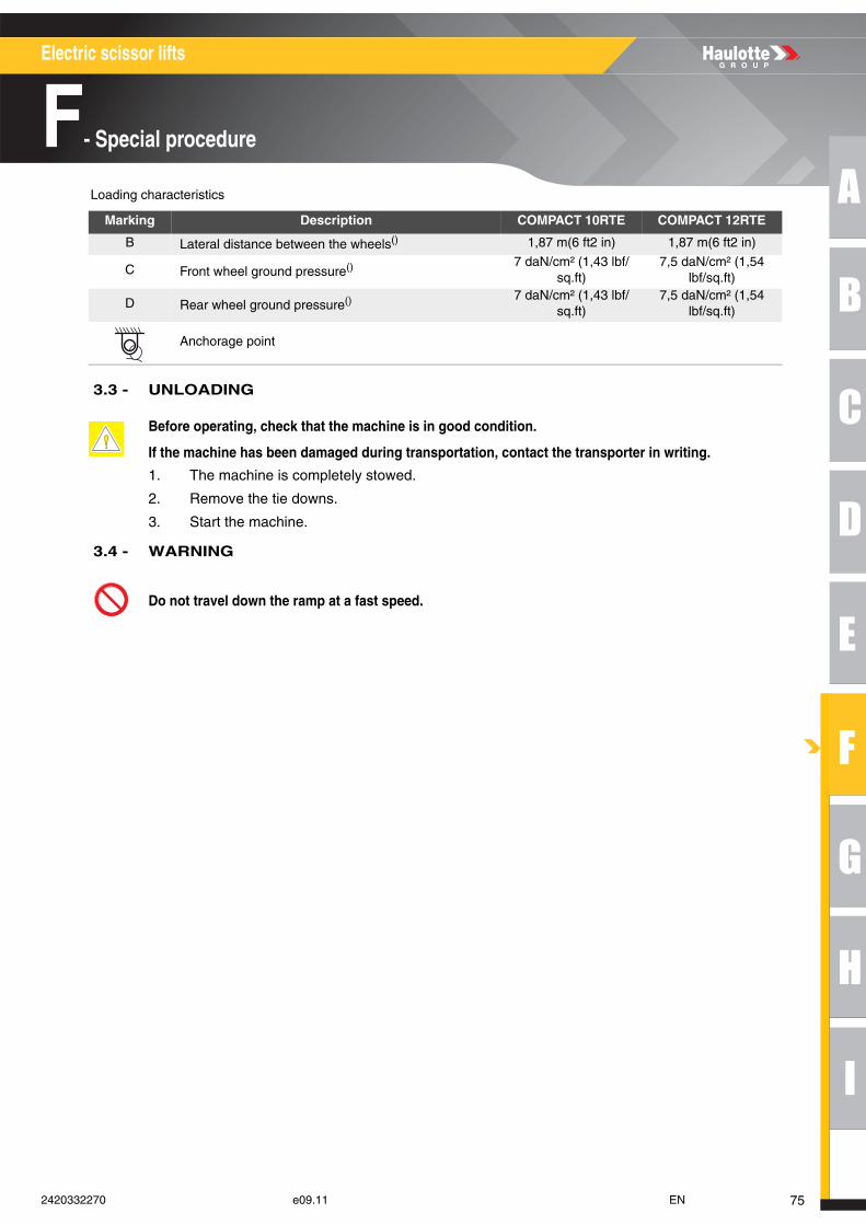
A
B
C
D
E
F
G
H
I
Electric scissor lifts
F- Special procedure
Loading characteristics
3.3 - UNLOADING
1. The machine is completely stowed.
2. Remove the tie downs.
3. Start the machine.
3.4 - WARNING
Marking Description COMPACT 10RTE COMPACT 12RTE
B Lateral distance between the wheels() 1,87 m(6 ft2 in) 1,87 m(6 ft2 in)
C Front wheel ground pressure() 7 daN/cm² (1,43 lbf/sq.ft)
7,5 daN/cm² (1,54 lbf/sq.ft)
D Rear wheel ground pressure() 7 daN/cm² (1,43 lbf/sq.ft)
7,5 daN/cm² (1,54 lbf/sq.ft)
Anchorage point
Before operating, check that the machine is in good condition.
If the machine has been damaged during transportation, contact the transporter in writing.
Do not travel down the ramp at a fast speed.
752420332270 e09.11 EN

Electric scissor lifts
F- Special procedure
76 2420332270 e09.11 EN
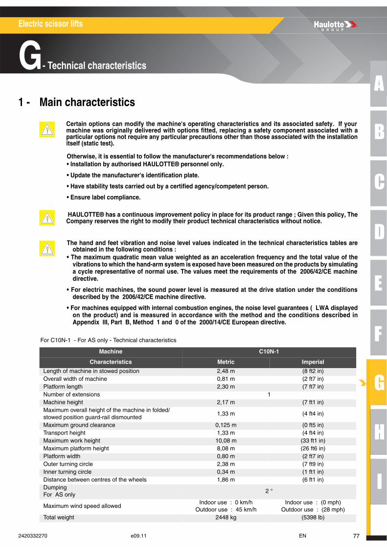
A
B
C
D
E
F
G
H
I
Electric scissor lifts
G- Technical characteristics
Technical characteristics1 - Main characteristics
For C10N-1 - For AS only - Technical characteristics
Certain options can modify the machine's operating characteristics and its associated safety. If yourmachine was originally delivered with options fitted, replacing a safety component associated with aparticular options not require any particular precautions other than those associated with the installationitself (static test).
Otherwise, it is essential to follow the manufacturer's recommendations below : • Installation by authorised HAULOTTE® personnel only.
• Update the manufacturer's identification plate.
• Have stability tests carried out by a certified agency/competent person.
• Ensure label compliance.
HAULOTTE® has a continuous improvement policy in place for its product range ; Given this policy, TheCompany reserves the right to modify their product technical characteristics without notice.
The hand and feet vibration and noise level values indicated in the technical characteristics tables areobtained in the following conditions :
• The maximum quadratic mean value weighted as an acceleration frequency and the total value of thevibrations to which the hand-arm system is exposed have been measured on the products by simulatinga cycle representative of normal use. The values meet the requirements of the 2006/42/CE machinedirective.
• For electric machines, the sound power level is measured at the drive station under the conditionsdescribed by the 2006/42/CE machine directive.
• For machines equipped with internal combustion engines, the noise level guarantees ( LWA displayedon the product) and is measured in accordance with the method and the conditions described inAppendix III, Part B, Method 1 and 0 of the 2000/14/CE European directive.
Machine C10N-1
Characteristics Metric Imperial
Length of machine in stowed position 2,48 m (8 ft2 in)Overall width of machine 0,81 m (2 ft7 in)Platform length 2,30 m (7 ft7 in)Number of extensions 1Machine height 2,17 m (7 ft1 in)Maximum overall height of the machine in folded/stowed position guard-rail dismounted
1,33 m (4 ft4 in)
Maximum ground clearance 0,125 m (0 ft5 in)Transport height 1,33 m (4 ft4 in)Maximum work height 10,08 m (33 ft1 in)Maximum platform height 8,08 m (26 ft6 in)Platform width 0,80 m (2 ft7 in)Outer turning circle 2,38 m (7 ft9 in)Inner turning circle 0,34 m (1 ft1 in)Distance between centres of the wheels 1,86 m (6 ft1 in)DumpingFor AS only
2 °
Maximum wind speed allowedIndoor use : 0 km/h
Outdoor use : 45 km/h Indoor use : (0 mph)
Outdoor use : (28 mph) Total weight 2448 kg (5398 lb)
772420332270 e09.11 EN
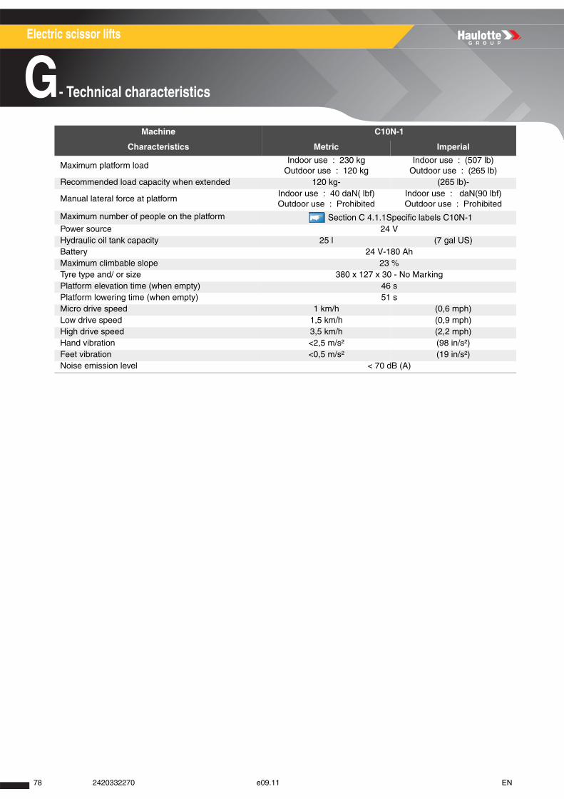
Electric scissor lifts
G- Technical characteristics
Maximum platform loadIndoor use : 230 kg
Outdoor use : 120 kgIndoor use : (507 lb)
Outdoor use : (265 lb)Recommended load capacity when extended 120 kg- (265 lb)-
Manual lateral force at platformIndoor use : 40 daN( lbf)Outdoor use : Prohibited
Indoor use : daN(90 lbf)Outdoor use : Prohibited
Maximum number of people on the platform Section C 4.1.1Specific labels C10N-1 Power source 24 VHydraulic oil tank capacity 25 l (7 gal US)Battery 24 V-180 AhMaximum climbable slope 23 %Tyre type and/ or size 380 x 127 x 30 - No MarkingPlatform elevation time (when empty) 46 sPlatform lowering time (when empty) 51 sMicro drive speed 1 km/h (0,6 mph) Low drive speed 1,5 km/h (0,9 mph) High drive speed 3,5 km/h (2,2 mph) Hand vibration <2,5 m/s² (98 in/s²)Feet vibration <0,5 m/s² (19 in/s²)Noise emission level < 70 dB (A)
Machine C10N-1
Characteristics Metric Imperial
78 2420332270 e09.11 EN
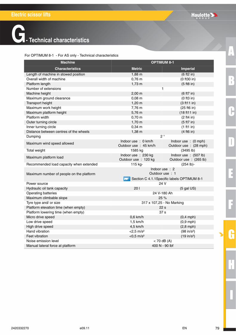
A
B
C
D
E
F
G
H
I
Electric scissor lifts
G- Technical characteristics
For OPTIMUM 8-1 - For AS only - Technical characteristics
Machine OPTIMUM 8-1
Characteristics Metric Imperial
Length of machine in stowed position 1,88 m (6 ft2 in)Overall width of machine 0,76 m (0 ft30 in)Platform length 1,73 m (5 ft8 in)Number of extensions 1Machine height 2,00 m (6 ft7 in)Maximum ground clearance 0,08 m (0 ft3 in)Transport height 1,20 m (3 ft11 in)Maximum work height 7,76 m (25 ft6 in)Maximum platform height 5,76 m (18 ft11 in)Platform width 0,70 m (2 ft4 in)Outer turning circle 1,70 m (5 ft7 in)Inner turning circle 0,34 m (1 ft1 in)Distance between centres of the wheels 1,38 m (4 ft6 in)Dumping 2 °
Maximum wind speed allowedIndoor use : 0 km/h
Outdoor use : 45 km/h Indoor use : (0 mph)
Outdoor use : (28 mph) Total weight 1585 kg (3495 lb)
Maximum platform loadIndoor use : 230 kg
Outdoor use : 120 kgIndoor use : (507 lb)
Outdoor use : (265 lb)Recommended load capacity when extended 115 kg- (254 lb)-
Maximum number of people on the platformIndoor use : 2
Outdoor use : 1
Section C 4.1.1Specific labels OPTIMUM 8-1 Power source 24 VHydraulic oil tank capacity 20 l (5 gal US)Operating batteries 24 V-180 AhMaximum climbable slope 25 %Tyre type and/ or size 317 x 107,25 - No MarkingPlatform elevation time (when empty) 22 sPlatform lowering time (when empty) 37 sMicro drive speed 0,6 km/h (0,4 mph) Low drive speed 1,5 km/h (0,9 mph) High drive speed 4,5 km/h (2,8 mph) Hand vibration <2,5 m/s² (98 in/s²)Feet vibration <0,5 m/s² (19 in/s²)Noise emission level < 70 dB (A)Manual lateral force at platform 400 N - 90 lbf
792420332270 e09.11 EN
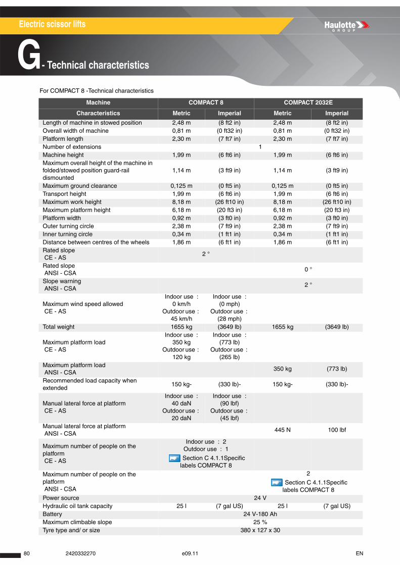
Electric scissor lifts
G- Technical characteristics
For COMPACT 8 -Technical characteristics
Machine COMPACT 8 COMPACT 2032E
Characteristics Metric Imperial Metric Imperial
Length of machine in stowed position 2,48 m (8 ft2 in) 2,48 m (8 ft2 in)Overall width of machine 0,81 m (0 ft32 in) 0,81 m (0 ft32 in)Platform length 2,30 m (7 ft7 in) 2,30 m (7 ft7 in)Number of extensions 1Machine height 1,99 m (6 ft6 in) 1,99 m (6 ft6 in)Maximum overall height of the machine in folded/stowed position guard-rail dismounted
1,14 m (3 ft9 in) 1,14 m (3 ft9 in)
Maximum ground clearance 0,125 m (0 ft5 in) 0,125 m (0 ft5 in)Transport height 1,99 m (6 ft6 in) 1,99 m (6 ft6 in)Maximum work height 8,18 m (26 ft10 in) 8,18 m (26 ft10 in)Maximum platform height 6,18 m (20 ft3 in) 6,18 m (20 ft3 in)Platform width 0,92 m (3 ft0 in) 0,92 m (3 ft0 in)Outer turning circle 2,38 m (7 ft9 in) 2,38 m (7 ft9 in)Inner turning circle 0,34 m (1 ft1 in) 0,34 m (1 ft1 in)Distance between centres of the wheels 1,86 m (6 ft1 in) 1,86 m (6 ft1 in)Rated slope CE - AS
2 °
Rated slope ANSI - CSA
0 °
Slope warning ANSI - CSA
2 °
Maximum wind speed allowed CE - AS
Indoor use : 0 km/h
Outdoor use : 45 km/h
Indoor use : (0 mph)
Outdoor use : (28 mph)
Total weight 1655 kg (3649 lb) 1655 kg (3649 lb)
Maximum platform load CE - AS
Indoor use : 350 kg
Outdoor use : 120 kg
Indoor use : (773 lb)
Outdoor use : (265 lb)
Maximum platform load ANSI - CSA
350 kg (773 lb)
Recommended load capacity when extended
150 kg- (330 lb)- 150 kg- (330 lb)-
Manual lateral force at platform CE - AS
Indoor use : 40 daN
Outdoor use : 20 daN
Indoor use : (90 lbf)
Outdoor use : (45 lbf)
Manual lateral force at platform ANSI - CSA
445 N 100 lbf
Maximum number of people on the platform CE - AS
Indoor use : 2Outdoor use : 1
Section C 4.1.1Specific labels COMPACT 8
Maximum number of people on the platform ANSI - CSA
2
Section C 4.1.1Specific labels COMPACT 8
Power source 24 VHydraulic oil tank capacity 25 l (7 gal US) 25 l (7 gal US)Battery 24 V-180 AhMaximum climbable slope 25 %Tyre type and/ or size 380 x 127 x 30
80 2420332270 e09.11 EN
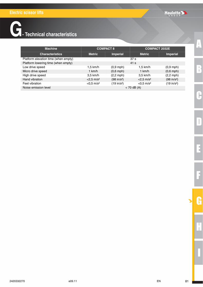
A
B
C
D
E
F
G
H
I
Electric scissor lifts
G- Technical characteristics
Platform elevation time (when empty) 37 sPlatform lowering time (when empty) 41 sLow drive speed 1,5 km/h (0,9 mph) 1,5 km/h (0,9 mph) Micro drive speed 1 km/h (0,6 mph) 1 km/h (0,6 mph) High drive speed 3,5 km/h (2,2 mph) 3,5 km/h (2,2 mph) Hand vibration <2,5 m/s² (98 in/s²) <2,5 m/s² (98 in/s²)Feet vibration <0,5 m/s² (19 in/s²) <0,5 m/s² (19 in/s²)Noise emission level < 70 dB (A)
Machine COMPACT 8 COMPACT 2032E
Characteristics Metric Imperial Metric Imperial
812420332270 e09.11 EN
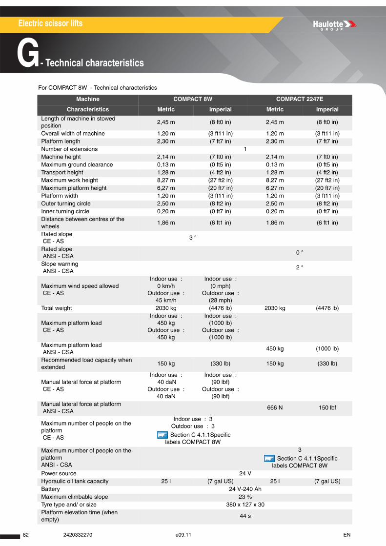
Electric scissor lifts
G- Technical characteristics
For COMPACT 8W - Technical characteristics
Machine COMPACT 8W COMPACT 2247E
Characteristics Metric Imperial Metric Imperial
Length of machine in stowed position
2,45 m (8 ft0 in) 2,45 m (8 ft0 in)
Overall width of machine 1,20 m (3 ft11 in) 1,20 m (3 ft11 in)Platform length 2,30 m (7 ft7 in) 2,30 m (7 ft7 in)Number of extensions 1Machine height 2,14 m (7 ft0 in) 2,14 m (7 ft0 in)Maximum ground clearance 0,13 m (0 ft5 in) 0,13 m (0 ft5 in)Transport height 1,28 m (4 ft2 in) 1,28 m (4 ft2 in)Maximum work height 8,27 m (27 ft2 in) 8,27 m (27 ft2 in)Maximum platform height 6,27 m (20 ft7 in) 6,27 m (20 ft7 in)Platform width 1,20 m (3 ft11 in) 1,20 m (3 ft11 in)Outer turning circle 2,50 m (8 ft2 in) 2,50 m (8 ft2 in)Inner turning circle 0,20 m (0 ft7 in) 0,20 m (0 ft7 in)Distance between centres of the wheels
1,86 m (6 ft1 in) 1,86 m (6 ft1 in)
Rated slope CE - AS
3 °
Rated slope ANSI - CSA
0 °
Slope warning ANSI - CSA
2 °
Maximum wind speed allowed CE - AS
Indoor use : 0 km/h
Outdoor use : 45 km/h
Indoor use : (0 mph)
Outdoor use : (28 mph)
Total weight 2030 kg (4476 lb) 2030 kg (4476 lb)
Maximum platform load CE - AS
Indoor use : 450 kg
Outdoor use : 450 kg
Indoor use : (1000 lb)
Outdoor use : (1000 lb)
Maximum platform load ANSI - CSA
450 kg (1000 lb)
Recommended load capacity when extended
150 kg (330 lb) 150 kg (330 lb)
Manual lateral force at platform CE - AS
Indoor use : 40 daN
Outdoor use : 40 daN
Indoor use : (90 lbf)
Outdoor use : (90 lbf)
Manual lateral force at platform ANSI - CSA
666 N 150 lbf
Maximum number of people on the platform CE - AS
Indoor use : 3Outdoor use : 3
Section C 4.1.1Specific labels COMPACT 8W
Maximum number of people on the platformANSI - CSA
3
Section C 4.1.1Specific labels COMPACT 8W
Power source 24 VHydraulic oil tank capacity 25 l (7 gal US) 25 l (7 gal US)Battery 24 V-240 AhMaximum climbable slope 23 %Tyre type and/ or size 380 x 127 x 30Platform elevation time (when empty)
44 s
82 2420332270 e09.11 EN
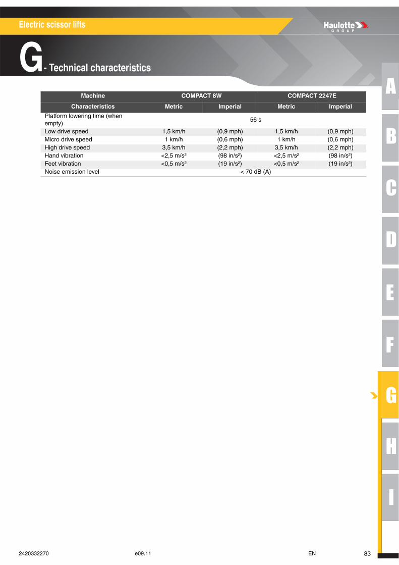
A
B
C
D
E
F
G
H
I
Electric scissor lifts
G- Technical characteristics
Platform lowering time (when empty)
56 s
Low drive speed 1,5 km/h (0,9 mph) 1,5 km/h (0,9 mph) Micro drive speed 1 km/h (0,6 mph) 1 km/h (0,6 mph) High drive speed 3,5 km/h (2,2 mph) 3,5 km/h (2,2 mph) Hand vibration <2,5 m/s² (98 in/s²) <2,5 m/s² (98 in/s²)Feet vibration <0,5 m/s² (19 in/s²) <0,5 m/s² (19 in/s²)Noise emission level < 70 dB (A)
Machine COMPACT 8W COMPACT 2247E
Characteristics Metric Imperial Metric Imperial
832420332270 e09.11 EN

Electric scissor lifts
G- Technical characteristics
For COMPACT 10N - Technical characteristics
Machine COMPACT 10N COMPACT 2632E
Characteristics Metric Imperial Metric Imperial
Length of machine in stowed position
2,48 m (8 ft2 in) 2,48 m (8 ft2 in)
Overall width of machine 0,81 m (2 ft8 in) 0,81 m (2 ft8 in)Platform length 2,30 m (7 ft7 in) 2,30 m (7 ft7 in)Number of extensions 1Machine height 2,17 m (7 ft1 in) 2,17 m (7 ft1 in)Maximum overall height of the machine in folded/stowed position guard-rail dismounted
1,33 m (4 ft4 in) 1,33 m (4 ft4 in)
Maximum ground clearance 0,125 m (0 ft5 in) 0,125 m (0 ft5 in)Transport height 1,33 m (4 ft4 in) 1,33 m (4 ft4 in)Maximum work height 10,08 m (33 ft1 in) 8 m (26 ft3 in)Maximum platform height 8,08 m (24 ft6 in) 8 m (26 ft3 in)Platform width 0,80 m (2 ft7 in) 0,80 m (2 ft7 in)Outer turning circle 2,38 m (7 ft9 in) 2,38 m (7 ft9 in)Inner turning circle 0,34 m (1 ft1 in) 0,34 m (1 ft1 in)Distance between centres of the wheels
1,86 m (6 ft1 in) 1,86 m (6 ft1 in)
Rated slope CE - AS
2 °
Rated slope ANSI - CSA
0 °
Slope warning ANSI - CSA
2 °
Maximum wind speed allowed CE - AS
Indoor use : 0 km/h
Outdoor use : 0 km/h
Indoor use : (0 mph)
Outdoor use : (0 mph)
Total weight 2190 kg (4829 lb) 2190 kg (4829 lb)
Maximum platform load CE - AS
Indoor use : 230 kg
Outdoor use : 0 kg
Indoor use : (507 lb)
Outdoor use : (0 lb)
Maximum platform load ANSI - CSA
230 kg (507 lb)
Recommended load capacity when extended
120 kg (265 lb) 120 kg (265 lb)
Manual lateral force at platform CE - AS
Indoor use : 40 daN
Outdoor use : Prohibited
Indoor use : (90 lbf)
Outdoor use : Prohibited
Manual lateral force at platform ANSI - CSA
445 N 100 lbf
Maximum number of people on the platform CE - AS
Indoor use : 2Outdoor use : 0
Section C 4.1.1Specific labels COMPACT 10N
Maximum number of people on the platform ANSI - CSA
2
Section C 4.1.1Specific labels COMPACT 10N
Power source 24 VHydraulic oil tank capacity 25 l (7 gal US) 25 l (7 gal US)Battery 24 V-180 AhMaximum climbable slope 23 %
84 2420332270 e09.11 EN

A
B
C
D
E
F
G
H
I
Electric scissor lifts
G- Technical characteristics
Tyre type and/ or size 380 x 127 x 30Platform elevation time (when empty)
46 s
Platform lowering time (when empty)
51 s
Micro drive speed 1,5 km/h (0,9 mph) 1,5 km/h (0,9 mph) Low drive speed 1 km/h (0,6 mph) 1 km/h (0,6 mph) High drive speed 3,5 km/h (2,2 mph) 3,5 km/h (2,2 mph) Hand vibration <2,5 m/s² (98 in/s²) <2,5 m/s² (98 in/s²)Feet vibration <0,5 m/s² (19 in/s²) <0,5 m/s² (19 in/s²)Noise emission level < 70 dB (A)
Machine COMPACT 10N COMPACT 2632E
Characteristics Metric Imperial Metric Imperial
852420332270 e09.11 EN

Electric scissor lifts
G- Technical characteristics
For COMPACT 10 - Technical characteristics
Machine COMPACT 10 COMPACT 2747E
Characteristics Metric Imperial Metric Imperial
Length of machine in stowed position
2,43 m (8 ft0 in) 2,43 m (8 ft0 in)
Overall width of machine 1,20 m (3 ft11 in) 1,20 m (3 ft11 in)Platform length 2,30 m (7 ft7 in) 2,30 m (7 ft7 in)Number of extensions 1Machine height 2,26 m (7 ft5 in) 2,26 m (7 ft5 in)Maximum overall height of the machine in folded/stowed position guard-rail dismounted
1,40 m (4 ft7 in) 1,40 m (4 ft7 in)
Maximum ground clearance 0,13 m (0 ft5 in) 0,13 m (0 ft5 in)Transport height 1,40 m (4 ft7 in) 1,40 m (4 ft7 in)Maximum work height 10,14 m (33 ft3 in) 10,14 m (33 ft3 in)Maximum platform height 8,14 m (26 ft8 in) 8,14 m (26 ft8 in)Platform width 1,20 m (3 ft11 in) 1,20 m (3 ft11 in)Outer turning circle 2,50 m (8 ft2 in) 2,50 m (8 ft2 in)Inner turning circle 0,20 m (0 ft7 in) 0,20 m (0 ft7 in)Distance between centres of the wheels
1,86 m (6 ft1 in) 1,86 m (6 ft1 in)
Rated slope CE - AS
2 °
Rated slope ANSI - CSA
0 °
Slope warning ANSI - CSA
2 °
Maximum wind speed allowed CE - AS
Indoor use : 0 km/h
Outdoor use : 45 km/h
Indoor use : (0 mph)
Outdoor use : (28 mph)
Total weight 2235 kg (4928 lb) 2235 kg (4928 lb)
Maximum platform load CE - AS
Indoor use : 450 kg
Outdoor use : 450 kg
Indoor use : (1000 lb)
Outdoor use : (1000 lb)
Maximum platform load ANSI - CSA
450 kg (1000 lb)
Recommended load capacity when extended
150 kg (330 lb) 150 kg (330 lb)
Manual lateral force at platform CE - AS
Indoor use : 40 daN
Outdoor use : 20 daN
Indoor use : (90 lbf)
Outdoor use : (45 lbf)
Manual lateral force at platform ANSI - CSA
666 N 150 lbf
Maximum number of people on the platform CE - AS
Indoor use : 2Outdoor use : 1
Section C 4.1.1Specific labels COMPACT 10
Maximum number of people on the platform ANSI - CSA
3
Section C 4.1.1Specific labels COMPACT 10
Power source 24 VHydraulic oil tank capacity 25 l (7 gal US) 25 l (7 gal US)Battery 24 V-240 AhMaximum climbable slope 23 %
86 2420332270 e09.11 EN

A
B
C
D
E
F
G
H
I
Electric scissor lifts
G- Technical characteristics
Tyre type and/ or size 380 x 127 x 30Platform elevation time (when empty)
51 s
Platform lowering time (when empty)
42 s
Micro drive speed 1,5 km/h (0,9 mph) 1,5 km/h (0,9 mph) Low drive speed 1 km/h (0,6 mph) 1 km/h (0,6 mph) High drive speed 3,5 km/h (2,2 mph) 3,5 km/h (2,2 mph) Hand vibration <2,5 m/s² (98 in/s²) <2,5 m/s² (98 in/s²)Feet vibration <0,5 m/s² (19 in/s²) <0,5 m/s² (19 in/s²)Noise emission level < 70 dB (A)
Machine COMPACT 10 COMPACT 2747E
Characteristics Metric Imperial Metric Imperial
872420332270 e09.11 EN
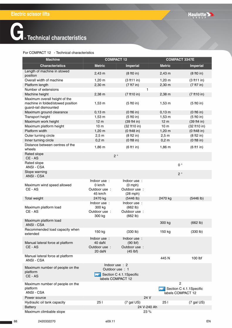
Electric scissor lifts
G- Technical characteristics
For COMPACT 12 - Technical characteristics
Machine COMPACT 12 COMPACT 3347E
Characteristics Metric Imperial Metric Imperial
Length of machine in stowed position
2,43 m (8 ft0 in) 2,43 m (8 ft0 in)
Overall width of machine 1,20 m (3 ft11 in) 1,20 m (3 ft11 in)Platform length 2,30 m (7 ft7 in) 2,30 m (7 ft7 in)Number of extensions 1Machine height 2,38 m (7 ft10 in) 2,38 m (7 ft10 in)Maximum overall height of the machine in folded/stowed position guard-rail dismounted
1,53 m (5 ft0 in) 1,53 m (5 ft0 in)
Maximum ground clearance 0,13 m (0 ft6 in) 0,13 m (0 ft6 in)Transport height 1,53 m (5 ft0 in) 1,53 m (5 ft0 in)Maximum work height 12 m (39 ft4 in) 12 m (39 ft4 in)Maximum platform height 10 m (32 ft10 in) 10 m (32 ft10 in)Platform width 1,20 m (0 ft48 in) 1,20 m (0 ft48 in)Outer turning circle 2,5 m (8 ft2 in) 2,5 m (8 ft2 in)Inner turning circle 0,2 m (0 ft8 in) 0,2 m (0 ft8 in)Distance between centres of the wheels
1,86 m (6 ft1 in) 1,86 m (6 ft1 in)
Rated slope CE - AS
2 °
Rated slope ANSI - CSA
0 °
Slope warning ANSI - CSA
2 °
Maximum wind speed allowed CE - AS
Indoor use : 0 km/h
Outdoor use : 45 km/h
Indoor use : (0 mph)
Outdoor use : (28 mph)
Total weight 2470 kg (5446 lb) 2470 kg (5446 lb)
Maximum platform load CE - AS
Indoor use : 300 kg
Outdoor use : 300 kg
Indoor use : (662 lb)
Outdoor use : (662 lb)
Maximum platform load ANSI - CSA
300 kg (662 lb)
Recommended load capacity when extended
150 kg (330 lb) 150 kg (330 lb)
Manual lateral force at platform CE - AS
Indoor use : 40 daN
Outdoor use : 20 daN
Indoor use : (90 lbf)
Outdoor use : (45 lbf)
Manual lateral force at platform ANSI - CSA
445 N 100 lbf
Maximum number of people on the platform CE - AS
Indoor use : 2Outdoor use : 1
Section C 4.1.1Specific labels COMPACT 12
Maximum number of people on the platform ANSI - CSA
2
Section C 4.1.1Specific labels COMPACT 12
Power source 24 VHydraulic oil tank capacity 25 l (7 gal US) 25 l (7 gal US)Battery 24 V-240 AhMaximum climbable slope 23 %
88 2420332270 e09.11 EN
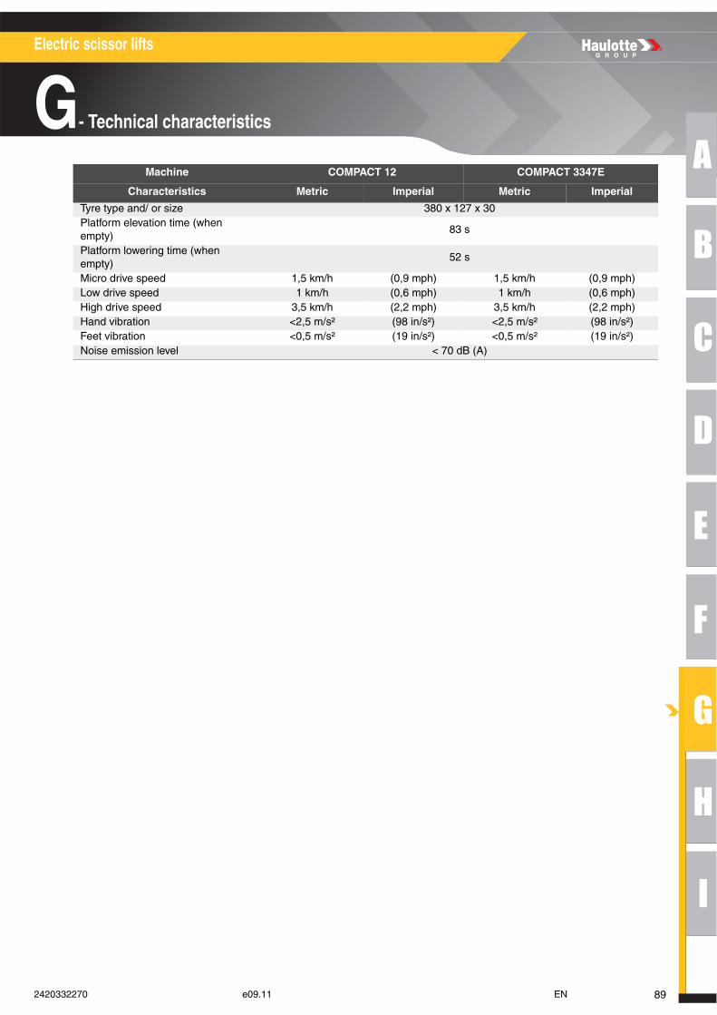
A
B
C
D
E
F
G
H
I
Electric scissor lifts
G- Technical characteristics
Tyre type and/ or size 380 x 127 x 30Platform elevation time (when empty)
83 s
Platform lowering time (when empty)
52 s
Micro drive speed 1,5 km/h (0,9 mph) 1,5 km/h (0,9 mph) Low drive speed 1 km/h (0,6 mph) 1 km/h (0,6 mph) High drive speed 3,5 km/h (2,2 mph) 3,5 km/h (2,2 mph) Hand vibration <2,5 m/s² (98 in/s²) <2,5 m/s² (98 in/s²)Feet vibration <0,5 m/s² (19 in/s²) <0,5 m/s² (19 in/s²)Noise emission level < 70 dB (A)
Machine COMPACT 12 COMPACT 3347E
Characteristics Metric Imperial Metric Imperial
892420332270 e09.11 EN
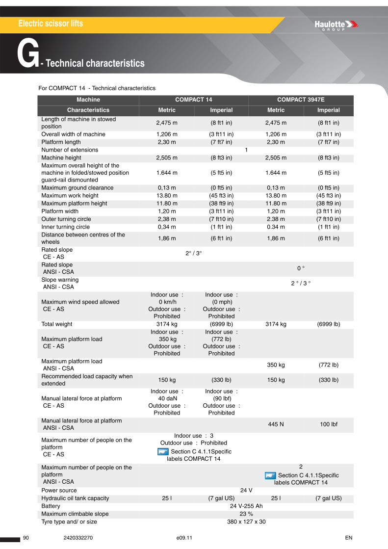
Electric scissor lifts
G- Technical characteristics
For COMPACT 14 - Technical characteristics
Machine COMPACT 14 COMPACT 3947E
Characteristics Metric Imperial Metric Imperial
Length of machine in stowed position
2,475 m (8 ft1 in) 2,475 m (8 ft1 in)
Overall width of machine 1,206 m (3 ft11 in) 1,206 m (3 ft11 in)Platform length 2,30 m (7 ft7 in) 2,30 m (7 ft7 in)Number of extensions 1Machine height 2,505 m (8 ft3 in) 2,505 m (8 ft3 in)Maximum overall height of the machine in folded/stowed position guard-rail dismounted
1.644 m (5 ft5 in) 1.644 m (5 ft5 in)
Maximum ground clearance 0,13 m (0 ft5 in) 0,13 m (0 ft5 in)Maximum work height 13.80 m (45 ft3 in) 13.80 m (45 ft3 in)Maximum platform height 11.80 m (38 ft9 in) 11.80 m (38 ft9 in)Platform width 1,20 m (3 ft11 in) 1,20 m (3 ft11 in)Outer turning circle 2,38 m (7 ft10 in) 2.38 m (7 ft10 in)Inner turning circle 0,34 m (1 ft1 in) 0.34 m (1 ft1 in)Distance between centres of the wheels
1,86 m (6 ft1 in) 1,86 m (6 ft1 in)
Rated slope CE - AS
2° / 3°
Rated slope ANSI - CSA
0 °
Slope warning ANSI - CSA
2 ° / 3 °
Maximum wind speed allowed CE - AS
Indoor use : 0 km/h
Outdoor use : Prohibited
Indoor use : (0 mph)
Outdoor use : Prohibited
Total weight 3174 kg (6999 lb) 3174 kg (6999 lb)
Maximum platform load CE - AS
Indoor use : 350 kg
Outdoor use : Prohibited
Indoor use : (772 lb)
Outdoor use : Prohibited
Maximum platform load ANSI - CSA
350 kg (772 lb)
Recommended load capacity when extended
150 kg (330 lb) 150 kg (330 lb)
Manual lateral force at platform CE - AS
Indoor use : 40 daN
Outdoor use : Prohibited
Indoor use : (90 lbf)
Outdoor use : Prohibited
Manual lateral force at platform ANSI - CSA
445 N 100 lbf
Maximum number of people on the platform CE - AS
Indoor use : 3Outdoor use : Prohibited
Section C 4.1.1Specific labels COMPACT 14
Maximum number of people on the platform ANSI - CSA
2
Section C 4.1.1Specific labels COMPACT 14
Power source 24 VHydraulic oil tank capacity 25 l (7 gal US) 25 l (7 gal US)Battery 24 V-255 AhMaximum climbable slope 23 %Tyre type and/ or size 380 x 127 x 30
90 2420332270 e09.11 EN

A
B
C
D
E
F
G
H
I
Electric scissor lifts
G- Technical characteristics
Platform elevation time (when empty)
68 s
Platform lowering time (when empty)
54 s
Micro drive speed 0.85 km/h (0.53 mph) 0.85 km/h (0.53 mph) High drive speed 2.8 km/h (1.7 mph) 2.8 km/h (1.7 mph) Hand vibration <2,5 m/s² (98 in/s²) <2,5 m/s² (98 in/s²)Feet vibration <0,5 m/s² (19 in/s²) <0,5 m/s² (19 in/s²)Noise emission level < 70 dB (A)
Machine COMPACT 14 COMPACT 3947E
Characteristics Metric Imperial Metric Imperial
912420332270 e09.11 EN

Electric scissor lifts
G- Technical characteristics
For OPTIMUM 6 - Technical characteristics
Machine OPTIMUM 6 OPTIMUM 1530E
Characteristics Metric Imperial Metric Imperial
Length of machine in stowed position
1.89 m (6 ft2 in) 1.89 m (6 ft2 in)
Overall width of machine 0,76 m (2 ft6 in) 0,76 m (2 ft6 in)Platform length 1.68 m (5 ft6 in) 1.68 m (5 ft6 in)Number of extensions 1Machine height 1,91 m (6 ft3 in) 1,91 m (6 ft3 in)Maximum ground clearance 0,08 m (0 ft3 in) 0,08 m (0 ft3 in)Maximum overall height of the machine in folded/stowed position guard-rail dismounted
1.04 m (3 ft5 in) 1.04 m (3 ft5 in)
Maximum work height 6.35 m (20 ft10 in) 6.35 m (20 ft10 in)Maximum platform height 4.35 m (14 ft3 in) 4.35 m (14 ft3 in)Platform width 0,70 m (2 ft4 in) 0,70 m (2 ft4 in)Outer turning circle 1,70 m (5 ft7 in) 1,70 m (5 ft7 in)Inner turning circle 0,34 m (1 ft1 in) 0,34 m (1 ft1 in)Distance between centres of the wheels
1,38 m (4 ft6 in) 1,38 m (4 ft6 in)
Rated slope CE - AS
2°
Rated slope ANSI - CSA
0 °
Slope warning ANSI - CSA
2 °
Maximum wind speed allowed CE - AS
Indoor use : 0 km/h
Outdoor use : 45 km/h
Indoor use : (0 mph)
Outdoor use : (28 mph)
Total weight 1290 kg (2844 lb) 1290 kg (2844 lb)
Maximum platform loadCE - AS
Indoor use : 270 kg
Outdoor use : 270 kg
Indoor use : (595 lb)
Outdoor use : (595 lb)
Maximum platform load ANSI - CSA
270 kg (595 lb)
Recommended load capacity when extended
115 kg (254 lb) 115 kg (254 lb)
Manual lateral force at platform CE - AS
Indoor use : 40 daN
Outdoor use : 20 daN
Indoor use : (90 lbf)
Outdoor use : (45 lbf)
Manual lateral force at platform ANSI - CSA
445 N 100 lbf
Maximum number of people on the platform CE - AS
Indoor use : 2Outdoor use : 1
Section C 4.1.1Specific labels OPTIMUM 6
Maximum number of people on the platform ANSI - CSA
2
Section C 4.1.1Specific labels OPTIMUM 6
Power source 24 VHydraulic oil tank capacity 20 l (5 gal US) 20 l (5 gal US)Battery 24 V-180 AhMaximum climbable slope 25 %Tyre type and/ or size 317 x 107 x 25
92 2420332270 e09.11 EN

A
B
C
D
E
F
G
H
I
Electric scissor lifts
G- Technical characteristics
Platform elevation time (when empty)
21 s
Platform lowering time (when empty)
37 s
Micro drive speed 0.5 km/h (0.31 mph) 0.5 km/h (0.31 mph) High drive speed 4,5 km/h (2,8 mph) 4,5 km/h (2,8 mph) Hand vibration <2,5 m/s² (98 in/s²) <2,5 m/s² (98 in/s²)Feet vibration <0,5 m/s² (19 in/s²) <0,5 m/s² (19 in/s²)Noise emission level < 70 dB (A)
Machine OPTIMUM 6 OPTIMUM 1530E
Characteristics Metric Imperial Metric Imperial
932420332270 e09.11 EN
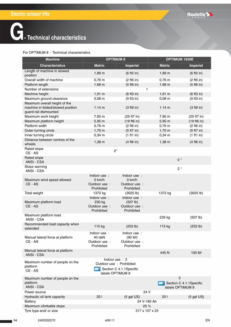
Electric scissor lifts
G- Technical characteristics
For OPTIMUM 8 - Technical characteristics
Machine OPTIMUM 8 OPTIMUM 1930E
Characteristics Metric Imperial Metric Imperial
Length of machine in stowed position
1.89 m (6 ft2 in) 1.89 m (6 ft2 in)
Overall width of machine 0,76 m (2 ft6 in) 0,76 m (2 ft6 in)Platform length 1.68 m (5 ft6 in) 1.68 m (5 ft6 in)Number of extensions 1Machine height 1,91 m (6 ft3 in) 1,91 m (6 ft3 in)Maximum ground clearance 0,08 m (0 ft3 in) 0,08 m (0 ft3 in)Maximum overall height of the machine in folded/stowed position guard-rail dismounted
1.14 m (3 ft9 in) 1.14 m (3 ft9 in)
Maximum work height 7.80 m (25 ft7 in) 7.80 m (25 ft7 in)Maximum platform height 5.95 m (19 ft6 in) 5.95 m (19 ft6 in)Platform width 0.76 m (2 ft6 in) 0,76 m (2 ft6 in)Outer turning circle 1,70 m (5 ft7 in) 1,70 m (5 ft7 in)Inner turning circle 0,34 m (1 ft1 in) 0,34 m (1 ft1 in)Distance between centres of the wheels
1,38 m (4 ft6 in) 1,38 m (4 ft6 in)
Rated slope CE - AS
2°
Rated slope ANSI - CSA
0 °
Slope warning ANSI - CSA
2 °
Maximum wind speed allowed CE - AS
Indoor use : 0 km/h
Outdoor use : Prohibited
Indoor use : 0 km/h
Outdoor use : Prohibited
Total weight 1372 kg (3025 lb) 1372 kg (3025 lb)
Maximum platform load CE - AS
Indoor use : 230 kg
Outdoor use : Prohibited
Indoor use : (507 lb)
Outdoor use : Prohibited
Maximum platform load ANSI - CSA
230 kg (507 lb)
Recommended load capacity when extended
115 kg (253 lb) 115 kg (253 lb)
Manual lateral force at platform CE - AS
Indoor use : 40 daN
Outdoor use : Prohibited
Indoor use : (90 lbf)
Outdoor use : Prohibited
Manual lateral force at platform ANSI - CSA
445 N 100 lbf
Maximum number of people on the platform CE - AS
Indoor use : 2Outdoor use : Prohibited
Section C 4.1.1Specific labels OPTIMUM 8
Maximum number of people on the platform ANSI - CSA
2
Section C 4.1.1Specific labels OPTIMUM 8
Power source 24 VHydraulic oil tank capacity 20 l (5 gal US) 20 l (5 gal US)Battery 24 V-180 AhMaximum climbable slope 25 %Tyre type and/ or size 317 x 107 x 25
94 2420332270 e09.11 EN

A
B
C
D
E
F
G
H
I
Electric scissor lifts
G- Technical characteristics
Platform elevation time (when empty)
23 s
Platform lowering time (when empty)
29 s
Micro drive speed 0.5 km/h (0,31 mph) 0.5 km/h (0,31 mph) High drive speed 4,5 km/h (2,8 mph) 4,5 km/h (2,8 mph) Hand vibration <2,5 m/s² (98 in/s²) <2,5 m/s² (98 in/s²)Feet vibration <0,5 m/s² (19 in/s²) <0,5 m/s² (19 in/s²)Noise emission level < 70 dB (A)
Machine OPTIMUM 8 OPTIMUM 1930E
Characteristics Metric Imperial Metric Imperial
952420332270 e09.11 EN
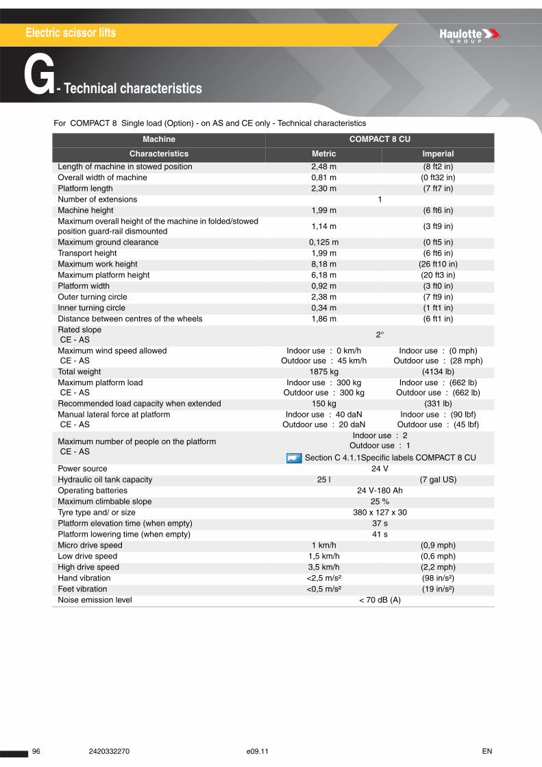
Electric scissor lifts
G- Technical characteristics
For COMPACT 8 Single load (Option) - on AS and CE only - Technical characteristics
Machine COMPACT 8 CU
Characteristics Metric Imperial
Length of machine in stowed position 2,48 m (8 ft2 in)Overall width of machine 0,81 m (0 ft32 in)Platform length 2,30 m (7 ft7 in)Number of extensions 1Machine height 1,99 m (6 ft6 in)Maximum overall height of the machine in folded/stowed position guard-rail dismounted
1,14 m (3 ft9 in)
Maximum ground clearance 0,125 m (0 ft5 in)Transport height 1,99 m (6 ft6 in)Maximum work height 8,18 m (26 ft10 in)Maximum platform height 6,18 m (20 ft3 in)Platform width 0,92 m (3 ft0 in)Outer turning circle 2,38 m (7 ft9 in)Inner turning circle 0,34 m (1 ft1 in)Distance between centres of the wheels 1,86 m (6 ft1 in)Rated slope CE - AS
2°
Maximum wind speed allowed CE - AS
Indoor use : 0 km/h Outdoor use : 45 km/h
Indoor use : (0 mph) Outdoor use : (28 mph)
Total weight 1875 kg (4134 lb)Maximum platform load CE - AS
Indoor use : 300 kgOutdoor use : 300 kg
Indoor use : (662 lb)Outdoor use : (662 lb)
Recommended load capacity when extended 150 kg (331 lb)Manual lateral force at platform CE - AS
Indoor use : 40 daNOutdoor use : 20 daN
Indoor use : (90 lbf)Outdoor use : (45 lbf)
Maximum number of people on the platform CE - AS
Indoor use : 2Outdoor use : 1
Section C 4.1.1Specific labels COMPACT 8 CU Power source 24 VHydraulic oil tank capacity 25 l (7 gal US)Operating batteries 24 V-180 AhMaximum climbable slope 25 %Tyre type and/ or size 380 x 127 x 30Platform elevation time (when empty) 37 sPlatform lowering time (when empty) 41 sMicro drive speed 1 km/h (0,9 mph) Low drive speed 1,5 km/h (0,6 mph) High drive speed 3,5 km/h (2,2 mph) Hand vibration <2,5 m/s² (98 in/s²)Feet vibration <0,5 m/s² (19 in/s²)Noise emission level < 70 dB (A)
96 2420332270 e09.11 EN

A
B
C
D
E
F
G
H
I
Electric scissor lifts
G- Technical characteristics
For COMPACT 10RTE - Technical characteristics
Machine COMPACT 10RTE COMPACT 2668RTE
Characteristics Metric Imperial Metric Imperial
Length of machine in stowed position
2,65 m (8 ft8 in) 2,65 m (8 ft8 in)
Overall width of machine 1,80 m (0 ft71 in) 1,80 m (0 ft71 in)Platform length 2,50 m (8 ft2 in) 2,50 m (8 ft2 in)Number of extensions 1Machine height 2,42 m (7 ft11 in) 2,42 m (7 ft11 in)Maximum overall height of the machine in folded/stowed position guard-rail dismounted
1,51 m (4 ft11 in) 1,51 m (4 ft11 in)
Maximum ground clearance 0,25 m (0 ft10 in) 0,25 m (0 ft10 in)Transport height 1,51 m (4 ft11 in) 1,51 m (4 ft11 in)Maximum work height 10,25 m (33 ft8 in) 10,25 m (33 ft8 in)Maximum platform height 8,25 m (27 ft1 in) 8,25 m (27 ft1 in)Platform width 1,54 m (5 ft10 in) 1,54 m (5 ft10 in)Outer turning circle 3,73 m (12 ft3 in) 3,73 m (12 ft3 in)Inner turning circle 1,21 m (4 ft0 in) 1,21 m (4 ft0 in)Distance between centres of the wheels
1,87 m (6 ft2 in) 1,87 m (6 ft2 in)
Rated slope CE - AS
3°
Rated slope ANSI - CSA
0 °
Slope warning ANSI - CSA
2 °
Maximum wind speed allowed CE - AS
Indoor use : 0 km/h
Outdoor use : 45 km/h
Indoor use : (0 mph)
Outdoor use : (28 mph)
Total weight - Machine without stabilizers
3380 kg (7453 lb) 3380 kg (7453 lb)
Total weight - Machine with outriggers
3620 kg (7982 lb) 3620 kg (7982 lb)
Maximum platform load CE - AS
565 kg (1246 lb)
Maximum platform load ANSI - CSA
565 kg (1246 lb)
Recommended load capacity when extended
150 kg (330 lb) 150 kg (330 lb)
Manual lateral force at platform CE - AS
400 N 90 lbf
Manual lateral force at platform ANSI - CSA
445 N 100 lbf
Maximum number of people on the platform CE - AS
2
Section C 4.1.1Specific labels COMPACT 10RTE
Maximum number of people on the platform ANSI - CSA
2
Section C 4.1.1Specific labels COMPACT 10RTE
Power source 48 VAdditional power source 285 AhMaximum climbable slope 25 %Tyre type and/ or size 26 x 12 - 12
972420332270 e09.11 EN
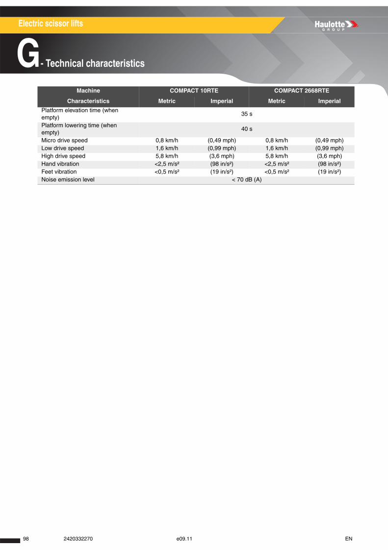
Electric scissor lifts
G- Technical characteristics
Platform elevation time (when empty)
35 s
Platform lowering time (when empty)
40 s
Micro drive speed 0,8 km/h (0,49 mph) 0,8 km/h (0,49 mph) Low drive speed 1,6 km/h (0,99 mph) 1,6 km/h (0,99 mph) High drive speed 5,8 km/h (3,6 mph) 5,8 km/h (3,6 mph) Hand vibration <2,5 m/s² (98 in/s²) <2,5 m/s² (98 in/s²)Feet vibration <0,5 m/s² (19 in/s²) <0,5 m/s² (19 in/s²)Noise emission level < 70 dB (A)
Machine COMPACT 10RTE COMPACT 2668RTE
Characteristics Metric Imperial Metric Imperial
98 2420332270 e09.11 EN
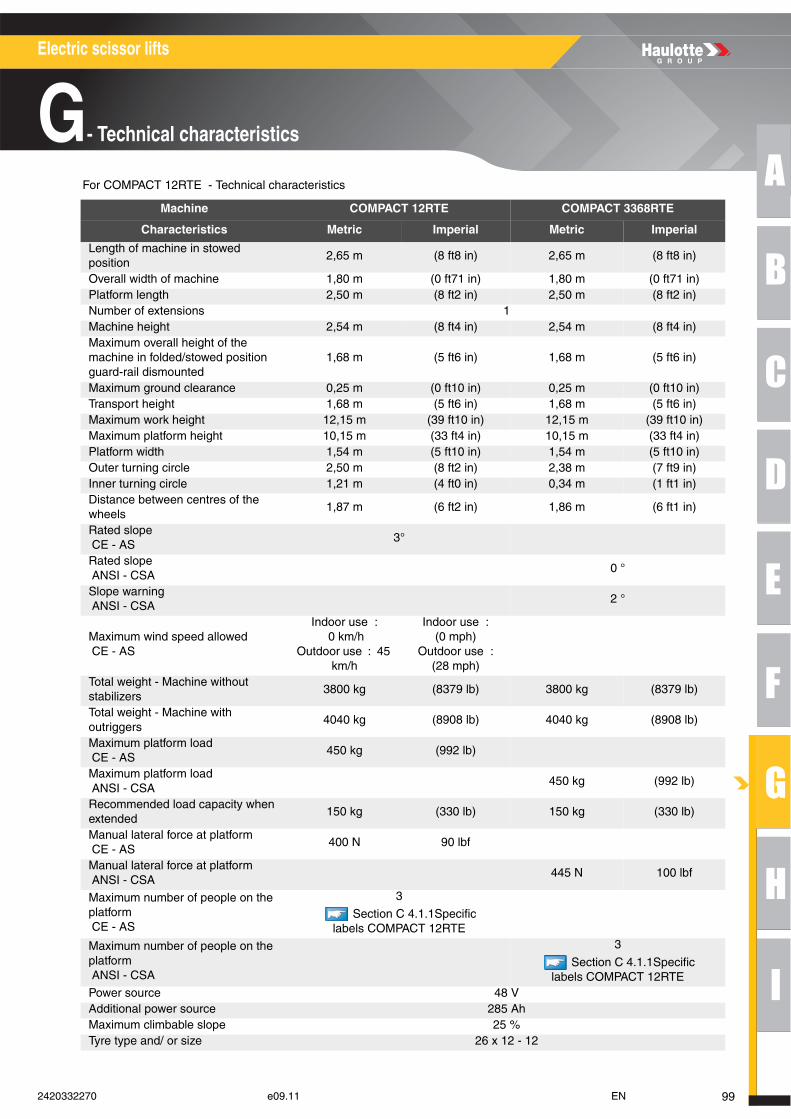
A
B
C
D
E
F
G
H
I
Electric scissor lifts
G- Technical characteristics
For COMPACT 12RTE - Technical characteristics
Machine COMPACT 12RTE COMPACT 3368RTE
Characteristics Metric Imperial Metric Imperial
Length of machine in stowed position
2,65 m (8 ft8 in) 2,65 m (8 ft8 in)
Overall width of machine 1,80 m (0 ft71 in) 1,80 m (0 ft71 in)Platform length 2,50 m (8 ft2 in) 2,50 m (8 ft2 in)Number of extensions 1Machine height 2,54 m (8 ft4 in) 2,54 m (8 ft4 in)Maximum overall height of the machine in folded/stowed position guard-rail dismounted
1,68 m (5 ft6 in) 1,68 m (5 ft6 in)
Maximum ground clearance 0,25 m (0 ft10 in) 0,25 m (0 ft10 in)Transport height 1,68 m (5 ft6 in) 1,68 m (5 ft6 in)Maximum work height 12,15 m (39 ft10 in) 12,15 m (39 ft10 in)Maximum platform height 10,15 m (33 ft4 in) 10,15 m (33 ft4 in)Platform width 1,54 m (5 ft10 in) 1,54 m (5 ft10 in)Outer turning circle 2,50 m (8 ft2 in) 2,38 m (7 ft9 in)Inner turning circle 1,21 m (4 ft0 in) 0,34 m (1 ft1 in)Distance between centres of the wheels
1,87 m (6 ft2 in) 1,86 m (6 ft1 in)
Rated slope CE - AS
3°
Rated slope ANSI - CSA
0 °
Slope warning ANSI - CSA
2 °
Maximum wind speed allowed CE - AS
Indoor use : 0 km/h
Outdoor use : 45 km/h
Indoor use : (0 mph)
Outdoor use : (28 mph)
Total weight - Machine without stabilizers
3800 kg (8379 lb) 3800 kg (8379 lb)
Total weight - Machine with outriggers
4040 kg (8908 lb) 4040 kg (8908 lb)
Maximum platform load CE - AS
450 kg (992 lb)
Maximum platform load ANSI - CSA
450 kg (992 lb)
Recommended load capacity when extended
150 kg (330 lb) 150 kg (330 lb)
Manual lateral force at platform CE - AS
400 N 90 lbf
Manual lateral force at platform ANSI - CSA
445 N 100 lbf
Maximum number of people on the platform CE - AS
3
Section C 4.1.1Specific labels COMPACT 12RTE
Maximum number of people on the platform ANSI - CSA
3
Section C 4.1.1Specific labels COMPACT 12RTE
Power source 48 VAdditional power source 285 AhMaximum climbable slope 25 %Tyre type and/ or size 26 x 12 - 12
992420332270 e09.11 EN

Electric scissor lifts
G- Technical characteristics
Platform elevation time (when empty)
50 s
Platform lowering time (when empty)
40 s
Micro drive speed 0,8 km/h (0,49 mph) 0,8 km/h (0,49 mph) Low drive speed 1,6 km/h (0,99 mph) 1,6 km/h (0,99 mph) High drive speed 5,8 km/h (3,6 mph) 5,8 km/h (3,6 mph) Hand vibration <2,5 m/s² (98 in/s²) <2,5 m/s² (98 in/s²)Feet vibration <0,5 m/s² (19 in/s²) <0,5 m/s² (19 in/s²)Noise emission level < 70 dB (A)
Machine COMPACT 12RTE COMPACT 3368RTE
Characteristics Metric Imperial Metric Imperial
100 2420332270 e09.11 EN
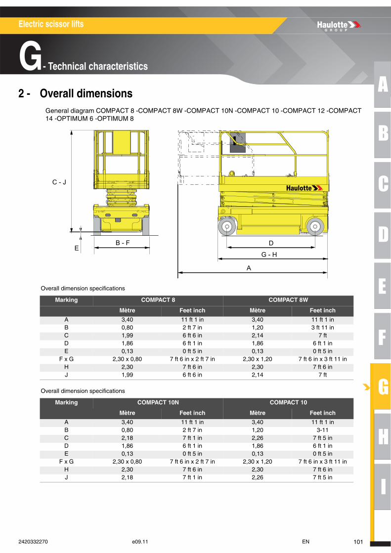
A
B
C
D
E
F
G
H
I
Electric scissor lifts
G- Technical characteristics
2 - Overall dimensionsGeneral diagram COMPACT 8 -COMPACT 8W -COMPACT 10N -COMPACT 10 -COMPACT 12 -COMPACT 14 -OPTIMUM 6 -OPTIMUM 8
Overall dimension specifications
Overall dimension specifications
Marking COMPACT 8 COMPACT 8W
Mètre Feet inch Mètre Feet inch
A 3,40 11 ft 1 in 3,40 11 ft 1 inB 0,80 2 ft 7 in 1,20 3 ft 11 inC 1,99 6 ft 6 in 2,14 7 ftD 1,86 6 ft 1 in 1,86 6 ft 1 inE 0,13 0 ft 5 in 0,13 0 ft 5 in
F x G 2,30 x 0,80 7 ft 6 in x 2 ft 7 in 2,30 x 1,20 7 ft 6 in x 3 ft 11 inH 2,30 7 ft 6 in 2,30 7 ft 6 inJ 1,99 6 ft 6 in 2,14 7 ft
Marking COMPACT 10N COMPACT 10
Mètre Feet inch Mètre Feet inch
A 3,40 11 ft 1 in 3,40 11 ft 1 inB 0,80 2 ft 7 in 1,20 3-11C 2,18 7 ft 1 in 2,26 7 ft 5 inD 1,86 6 ft 1 in 1,86 6 ft 1 inE 0,13 0 ft 5 in 0,13 0 ft 5 in
F x G 2,30 x 0,80 7 ft 6 in x 2 ft 7 in 2,30 x 1,20 7 ft 6 in x 3 ft 11 inH 2,30 7 ft 6 in 2,30 7 ft 6 inJ 2,18 7 ft 1 in 2,26 7 ft 5 in
G - H
D
A
B - F E
C - J
1012420332270 e09.11 EN
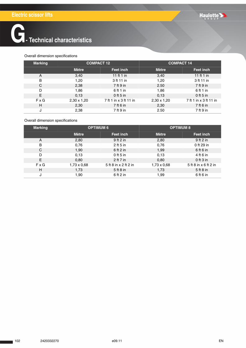
Electric scissor lifts
G- Technical characteristics
Overall dimension specifications
Overall dimension specifications
Marking COMPACT 12 COMPACT 14
Mètre Feet inch Mètre Feet inch
A 3,40 11 ft 1 in 3,40 11 ft 1 inB 1,20 3 ft 11 in 1,20 3 ft 11 inC 2,38 7 ft 9 in 2.50 7 ft 9 inD 1,86 6 ft 1 in 1,86 6 ft 1 inE 0,13 0 ft 5 in 0,13 0 ft 5 in
F x G 2,30 x 1,20 7 ft 1 in x 3 ft 11 in 2,30 x 1,20 7 ft 1 in x 3 ft 11 inH 2,30 7 ft 6 in 2,30 7 ft 6 inJ 2,38 7 ft 9 in 2.50 7 ft 9 in
Marking OPTIMUM 6 OPTIMUM 8
Mètre Feet inch Mètre Feet inch
A 2,80 9 ft 2 in 2,80 9 ft 2 inB 0,76 2 ft 5 in 0,76 0 ft 29 inC 1,90 6 ft 2 in 1,99 6 ft 6 inD 0,13 0 ft 5 in 0,13 4 ft 6 inE 0,80 2 ft 7 in 0,80 0 ft 3 in
F x G 1,73 x 0,68 5 ft 8 in x 2 ft 2 in 1,73 x 0,68 5 ft 8 in x 6 ft 2 inH 1,73 5 ft 8 in 1,73 5 ft 8 inJ 1,90 6 ft 2 in 1,99 6 ft 6 in
102 2420332270 e09.11 EN
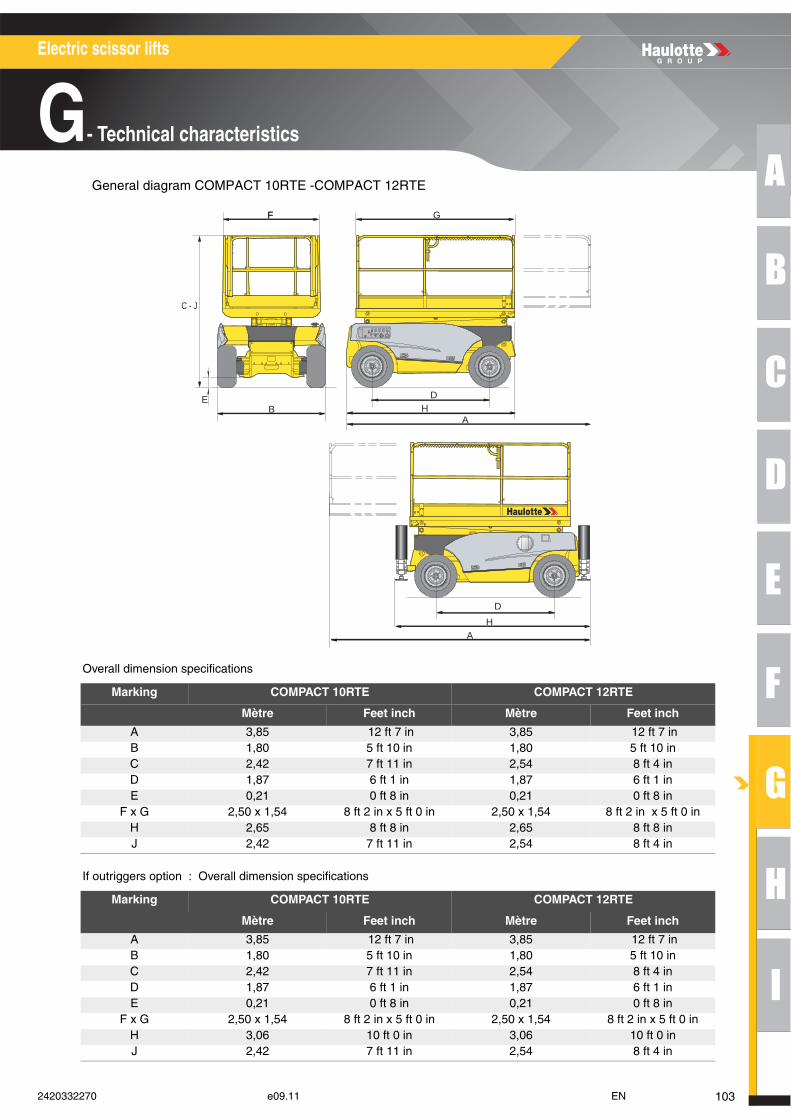
A
B
C
D
E
F
G
H
I
Electric scissor lifts
G- Technical characteristics
General diagram COMPACT 10RTE -COMPACT 12RTE
Overall dimension specifications
If outriggers option : Overall dimension specifications
Marking COMPACT 10RTE COMPACT 12RTE
Mètre Feet inch Mètre Feet inch
A 3,85 12 ft 7 in 3,85 12 ft 7 inB 1,80 5 ft 10 in 1,80 5 ft 10 inC 2,42 7 ft 11 in 2,54 8 ft 4 inD 1,87 6 ft 1 in 1,87 6 ft 1 inE 0,21 0 ft 8 in 0,21 0 ft 8 in
F x G 2,50 x 1,54 8 ft 2 in x 5 ft 0 in 2,50 x 1,54 8 ft 2 in x 5 ft 0 inH 2,65 8 ft 8 in 2,65 8 ft 8 inJ 2,42 7 ft 11 in 2,54 8 ft 4 in
Marking COMPACT 10RTE COMPACT 12RTE
Mètre Feet inch Mètre Feet inch
A 3,85 12 ft 7 in 3,85 12 ft 7 inB 1,80 5 ft 10 in 1,80 5 ft 10 inC 2,42 7 ft 11 in 2,54 8 ft 4 inD 1,87 6 ft 1 in 1,87 6 ft 1 inE 0,21 0 ft 8 in 0,21 0 ft 8 in
F x G 2,50 x 1,54 8 ft 2 in x 5 ft 0 in 2,50 x 1,54 8 ft 2 in x 5 ft 0 inH 3,06 10 ft 0 in 3,06 10 ft 0 inJ 2,42 7 ft 11 in 2,54 8 ft 4 in
B
HD
DE
A
H
C - J
A
FF G
1032420332270 e09.11 EN
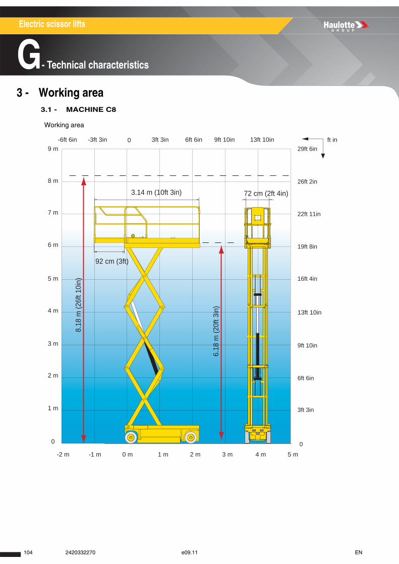
Electric scissor lifts
G- Technical characteristics
3 - Working area 3.1 - MACHINE C8
Working area
3.14 m (10ft 3in)
92 cm (3ft)
8.18
m (2
6ft 1
0in)
6.18
m (2
0ft 3
in)
72 cm (2ft 4in)
9 m
8 m
7 m
6 m
5 m
4 m
3 m
2 m
1 m
0
3ft 3in
6ft 6in
9ft 10in
13ft 10in
16ft 4in
19ft 8in
22ft 11in
26ft 2in
29ft 6in
0
6ft 6in 9ft 10in 13ft 10in-6ft 6in 0-3ft 3in 3ft 3in
0 m 1 m-1 m-2 m 2 m 3 m 4 m 5 m
ft in
104 2420332270 e09.11 EN
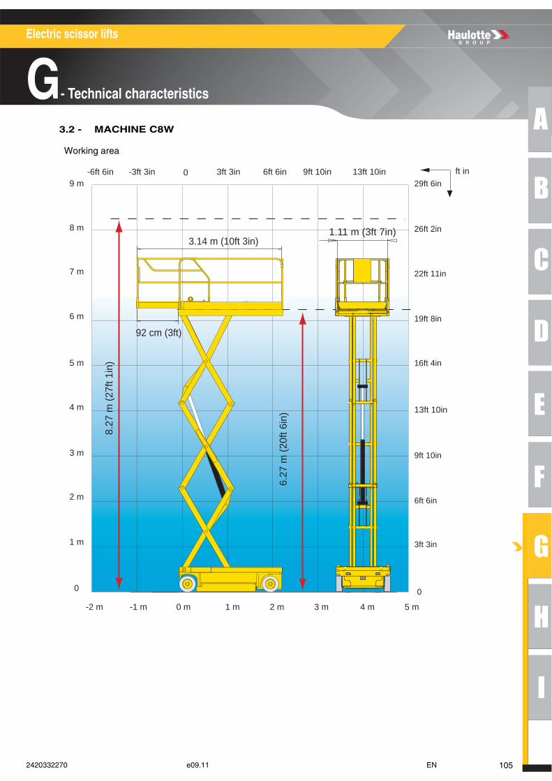
A
B
C
D
E
F
G
H
I
Electric scissor lifts
G- Technical characteristics
3.2 - MACHINE C8W
Working area
8.27
m (2
7ft 1
in)
6.27
m (2
0ft 6
in)
1.11 m (3ft 7in)3.14 m (10ft 3in)
6ft 6in 9ft 10in 13ft 10in-6ft 6in 0-3ft 3in 3ft 3in
0 m 1 m-1 m-2 m 2 m 3 m 4 m 5 m
92 cm (3ft)
9 m
8 m
7 m
6 m
5 m
4 m
3 m
2 m
1 m
0
3ft 3in
6ft 6in
9ft 10in
13ft 10in
16ft 4in
19ft 8in
22ft 11in
26ft 2in
29ft 6in
0
ft in
1052420332270 e09.11 EN
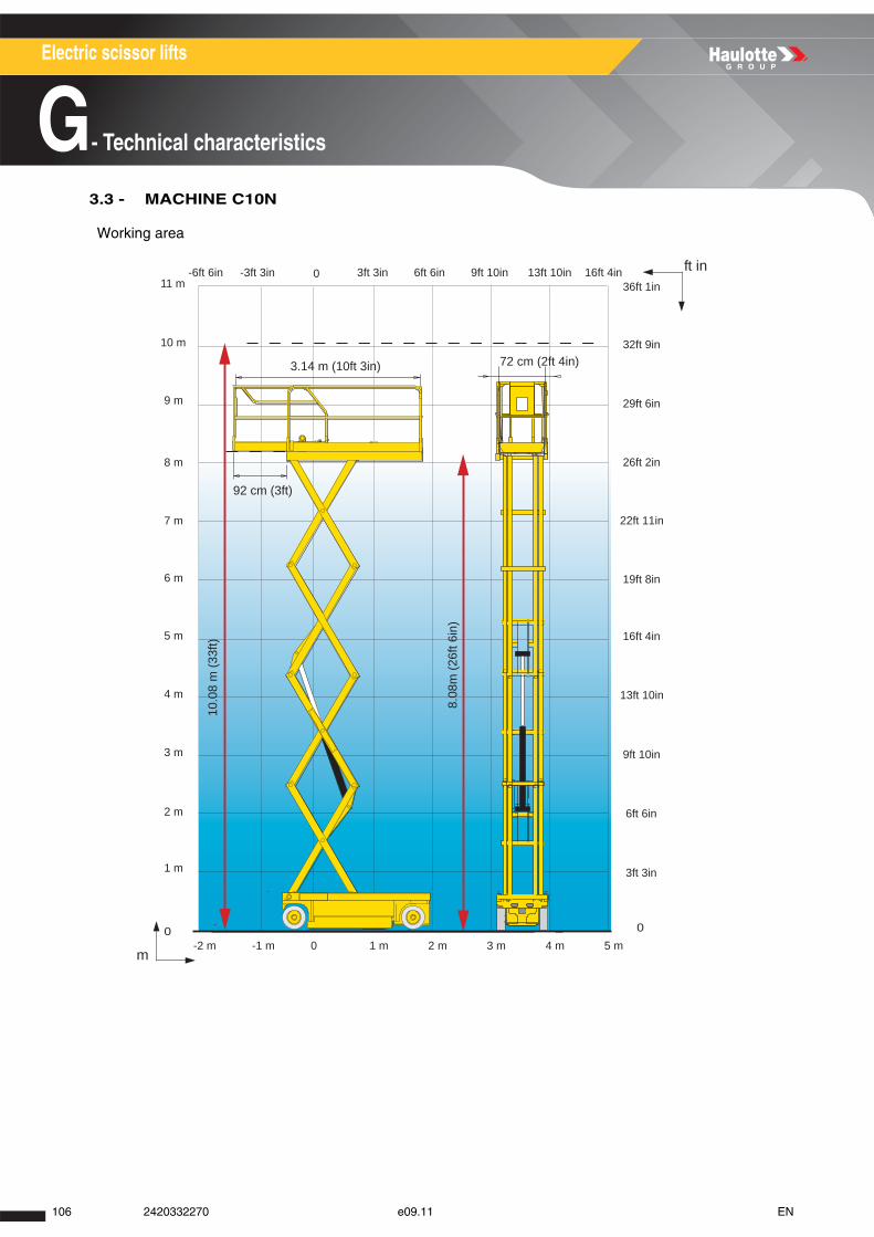
Electric scissor lifts
G- Technical characteristics
3.3 - MACHINE C10N
Working area
8.08
m (2
6ft 6
in)
10.0
8 m
(33f
t)
72 cm (2ft 4in)
92 cm (3ft)
3.14 m (10ft 3in)
-2 m -1 m 0 1 m 2 m 3 m 4 m 5 m
3ft 3in 6ft 6in 9ft 10in 13ft 10in 16ft 4in-3ft 3in-6ft 6in 011 m
10 m
9 m
8 m
7 m
6 m
5 m
4 m
3 m
2 m
1 m
0
3ft 3in
6ft 6in
9ft 10in
13ft 10in
16ft 4in
19ft 8in
22ft 11in
26ft 2in
29ft 6in
32ft 9in
36ft 1in
0
ft in
m
106 2420332270 e09.11 EN
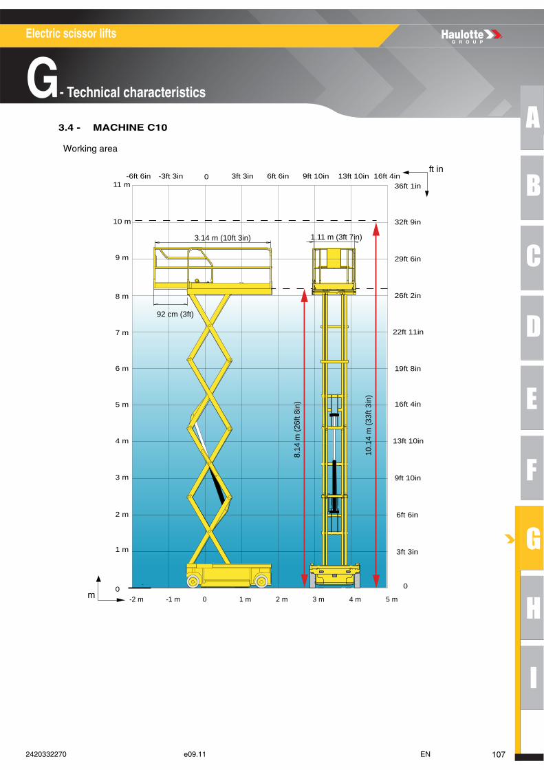
A
B
C
D
E
F
G
H
I
Electric scissor lifts
G- Technical characteristics
3.4 - MACHINE C10
Working area
10.1
4 m
(33f
t 3in
)
8.14
m (2
6ft 8
in)
3.14 m (10ft 3in) 1.11 m (3ft 7in)
92 cm (3ft)
-2 m -1 m 0 1 m 2 m 3 m 4 m 5 m
3ft 3in
6ft 6in
9ft 10in
13ft 10in
16ft 4in
19ft 8in
22ft 11in
26ft 2in
29ft 6in
32ft 9in
36ft 1in
0
11 m
10 m
9 m
8 m
7 m
6 m
5 m
4 m
3 m
2 m
1 m
0m
ft in3ft 3in 6ft 6in 9ft 10in 13ft 10in 16ft 4in-3ft 3in-6ft 6in 0
1072420332270 e09.11 EN
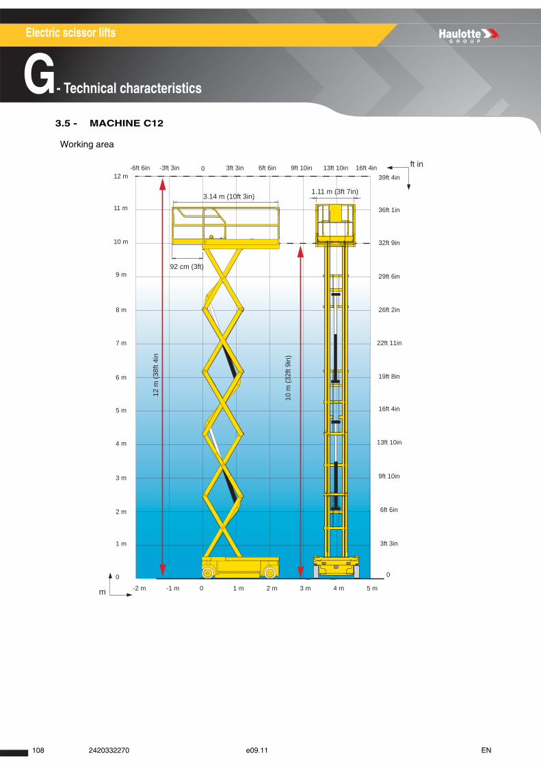
Electric scissor lifts
G- Technical characteristics
3.5 - MACHINE C12
Working area12
m (3
8ft 4
in
10 m
(32f
t 9in
)
3.14 m (10ft 3in)
92 cm (3ft)
1.11 m (3ft 7in)
-2 m -1 m 0 1 m 2 m 3 m 4 m 5 m
3ft 3in 6ft 6in 9ft 10in 13ft 10in 16ft 4in-3ft 3in-6ft 6in 0
11 m
12 m
10 m
9 m
8 m
7 m
6 m
5 m
4 m
3 m
2 m
1 m
0
3ft 3in
6ft 6in
9ft 10in
13ft 10in
16ft 4in
19ft 8in
22ft 11in
26ft 2in
29ft 6in
32ft 9in
36ft 1in
39ft 4in
0
ft in
m
108 2420332270 e09.11 EN
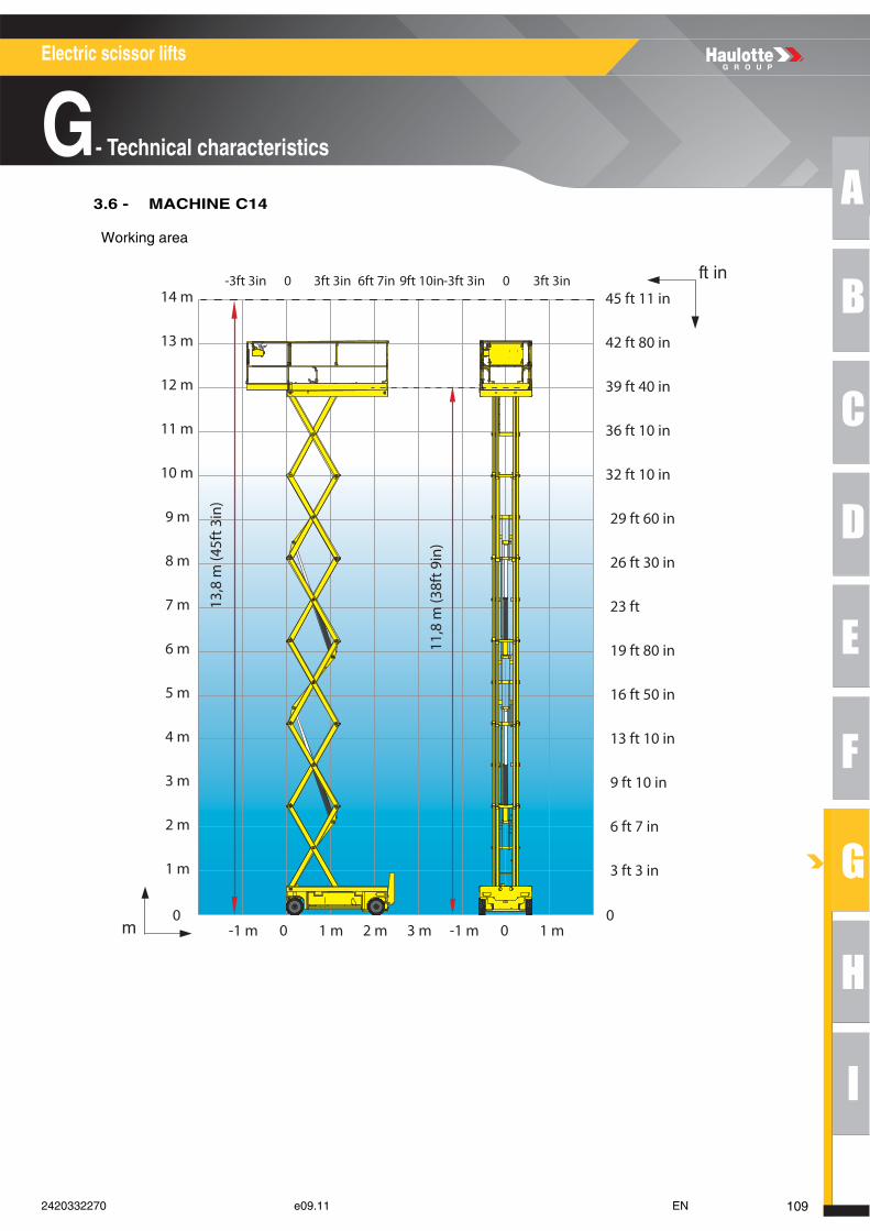
A
B
C
D
E
F
G
H
I
Electric scissor lifts
G- Technical characteristics
3.6 - MACHINE C14
Working area
ft in
m
14 m
13 m
12 m
11 m
10 m
9 m
8 m
7 m
6 m
5 m
4 m
3 m
2 m
1 m
0
45 ft 11 in
42 ft 80 in
39 ft 40 in
36 ft 10 in
32 ft 10 in
29 ft 60 in
26 ft 30 in
23 ft
19 ft 80 in
16 ft 50 in
13 ft 10 in
9 ft 10 in
6 ft 7 in
3 ft 3 in
0-1 m 1 m 2 m 3 m -1 m 0 1 m0
-3ft 3in 3ft 3in 6ft 7in 9ft 10in-3ft 3in 0 3ft 3in0
11,8
m (3
8ft 9
in)
13,8
m (4
5ft 3
in)
1092420332270 e09.11 EN
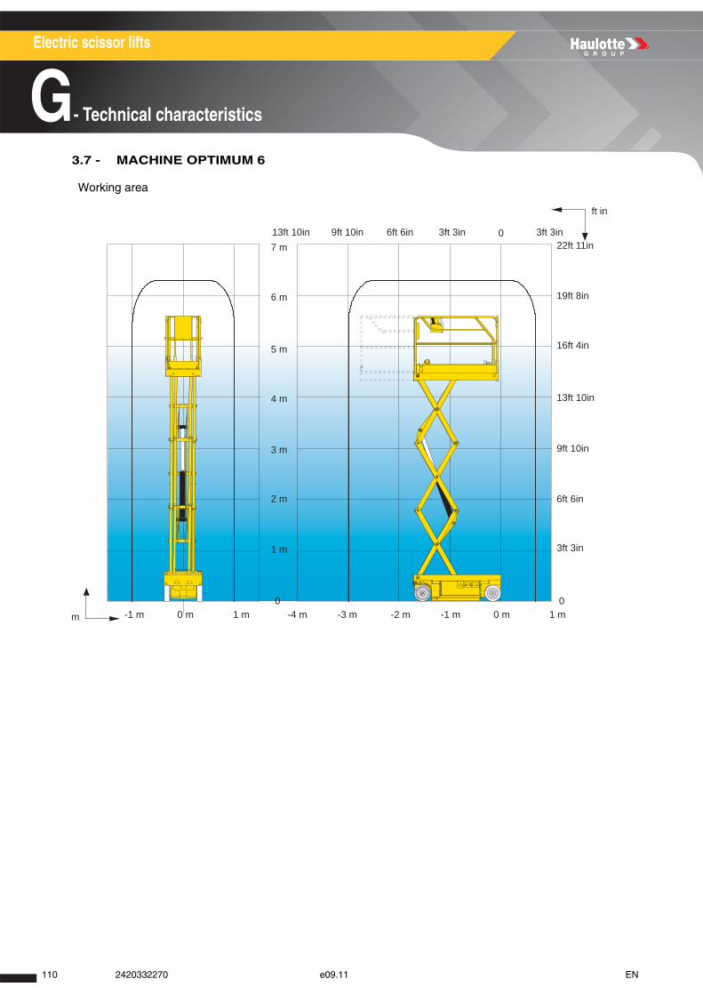
Electric scissor lifts
G- Technical characteristics
3.7 - MACHINE OPTIMUM 6
Working area
7 m
6 m
5 m
4 m
3 m
2 m
1 m
0
3ft 3in
6ft 6in
9ft 10in
13ft 10in
16ft 4in
19ft 8in
22ft 11in
00 m 1 m-1 m0 m 1 m-1 m -2 m-3 m-4 m
6ft 6in9ft 10in13ft 10in 0 3ft 3in3ft 3in
ft in
m
110 2420332270 e09.11 EN
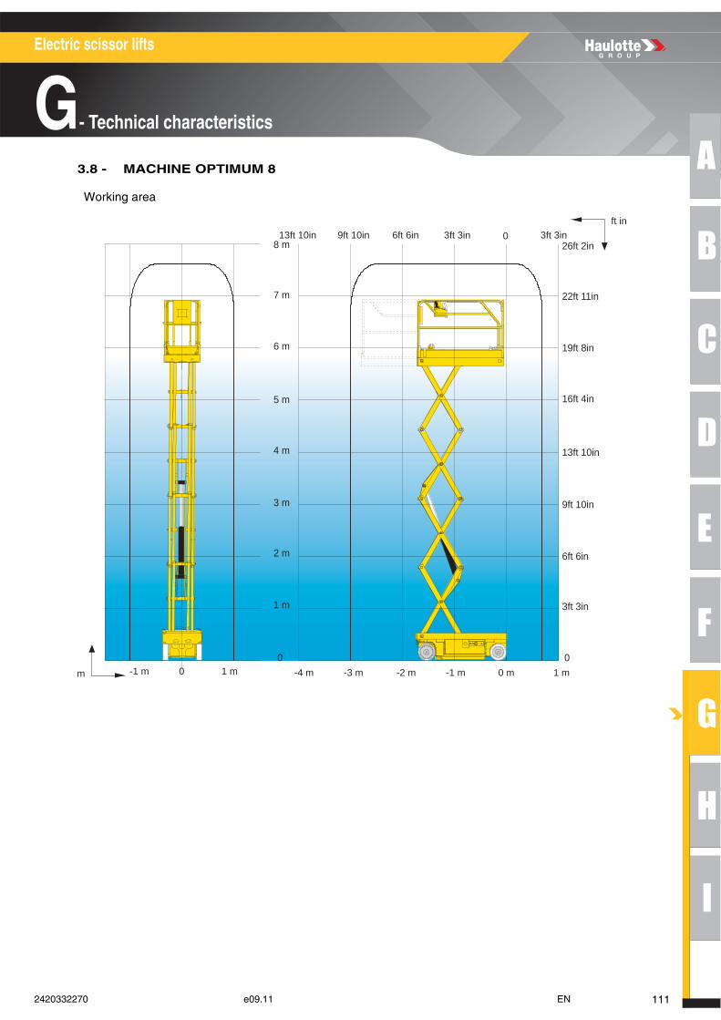
A
B
C
D
E
F
G
H
I
Electric scissor lifts
G- Technical characteristics
3.8 - MACHINE OPTIMUM 8
Working area
0 m 1 m-1 m-2 m-3 m-4 m
6ft 6in9ft 10in13ft 10in 0 3ft 3in3ft 3in
7 m
6 m
5 m
4 m
3 m
2 m
1 m
0
3ft 3in
6ft 6in
9ft 10in
13ft 10in
16ft 4in
19ft 8in
22ft 11in
8 m 26ft 2in
0
ft in
-1 m 0 1 mm
1112420332270 e09.11 EN
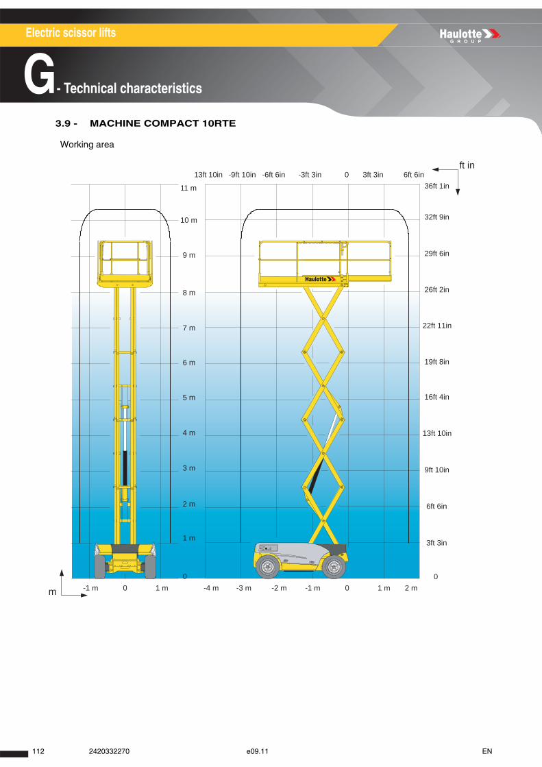
Electric scissor lifts
G- Technical characteristics
3.9 - MACHINE COMPACT 10RTE
Working area
11 m
10 m
9 m
8 m
7 m
6 m
5 m
4 m
3 m
2 m
1 m
0
3ft 3in
6ft 6in
9ft 10in
13ft 10in
16ft 4in
19ft 8in
22ft 11in
26ft 2in
29ft 6in
32ft 9in
36ft 1in
0-4 m -3 m -2 m -1 m 1 m 2 m0-1 m 1 m0
13ft 10in -6ft 6in-9ft 10in -3ft 3in 0 3ft 3in 6ft 6in
m
ft in
112 2420332270 e09.11 EN
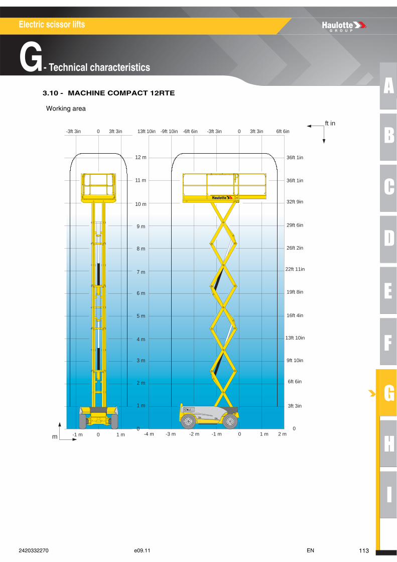
A
B
C
D
E
F
G
H
I
Electric scissor lifts
G- Technical characteristics
3.10 - MACHINE COMPACT 12RTE
Working area
-1 m 0 1 mm
ft in
-4 m -3 m -2 m -1 m 1 m 2 m0
13ft 10in -6ft 6in-9ft 10in -3ft 3in 0 3ft 3in-3ft 3in 0 3ft 3in 6ft 6in
11 m
12 m
10 m
9 m
8 m
7 m
6 m
5 m
4 m
3 m
2 m
1 m
0
3ft 3in
6ft 6in
9ft 10in
13ft 10in
16ft 4in
19ft 8in
22ft 11in
26ft 2in
29ft 6in
32ft 9in
36ft 1in
36ft 1in
0
1132420332270 e09.11 EN
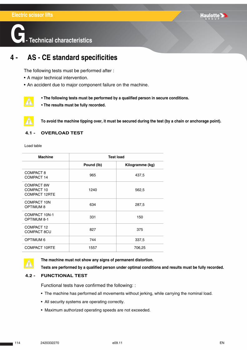
Electric scissor lifts
G- Technical characteristics
4 - AS - CE standard specificities
The following tests must be performed after :
• A major technical intervention.
• An accident due to major component failure on the machine.
4.1 - OVERLOAD TEST
Load table
4.2 - FUNCTIONAL TEST
Functional tests have confirmed the following: :
• The machine has performed all movements without jerking, while carrying the nominal load.
• All security systems are operating correctly.
• Maximum authorized operating speeds are not exceeded.
• The following tests must be performed by a qualified person in secure conditions.
• The results must be fully recorded.
To avoid the machine tipping over, it must be secured during the test (by a chain or anchorage point).
Machine Test load
Pound (lb) Kilogramme (kg)
COMPACT 8 COMPACT 14
965 437,5
COMPACT 8W COMPACT 10 COMPACT 12RTE
1240 562,5
COMPACT 10N OPTIMUM 8
634 287,5
COMPACT 10N-1 OPTIMUM 8-1
331 150
COMPACT 12 COMPACT 8CU
827 375
OPTIMUM 6 744 337,5
COMPACT 10RTE 1557 706,25
The machine must not show any signs of permanent distortion.
Tests are performed by a qualified person under optimal conditions and results must be fully recorded.
114 2420332270 e09.11 EN
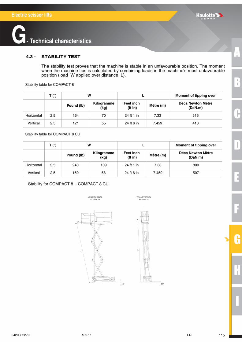
A
B
C
D
E
F
G
H
I
Electric scissor lifts
G- Technical characteristics
4.3 - STABILITY TEST
The stability test proves that the machine is stable in an unfavourable position. The momentwhen the machine tips is calculated by combining loads in the machine's most unfavourableposition (load W applied over distance L).
Stability table for COMPACT 8
Stability table for COMPACT 8 CU
Stability for COMPACT 8 - COMPACT 8 CU
T (°) W L Moment of tipping over
Pound (lb)Kilogramme
(kg)Feet inch
(ft in)Mètre (m)
Déca Newton Mètre (DaN.m)
Horizontal 2,5 154 70 24 ft 1 in 7.33 516
Vertical 2,5 121 55 24 ft 6 in 7.459 410
T (°) W L Moment of tipping over
Pound (lb)Kilogramme
(kg)Feet inch
(ft in)Mètre (m)
Déca Newton Mètre (DaN.m)
Horizontal 2,5 240 109 24 ft 1 in 7.33 800
Vertical 2,5 150 68 24 ft 6 in 7.459 507
W
L
2,5°
W
L
3,5°2.5°
LONGITUDINALPOSITION
TRANSVERSALPOSITION
1152420332270 e09.11 EN
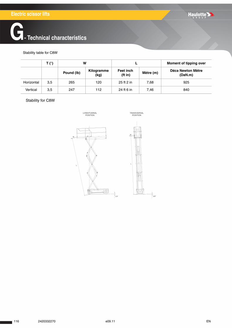
Electric scissor lifts
G- Technical characteristics
Stability table for C8W
Stability for C8W
T (°) W L Moment of tipping over
Pound (lb)Kilogramme
(kg)Feet inch
(ft in)Mètre (m)
Déca Newton Mètre (DaN.m)
Horizontal 3,5 265 120 25 ft 2 in 7,68 925
Vertical 3,5 247 112 24 ft 6 in 7,46 840
W
L
2,5°
W
L
3,5°2.5°
LONGITUDINALPOSITION
TRANSVERSALPOSITION
116 2420332270 e09.11 EN
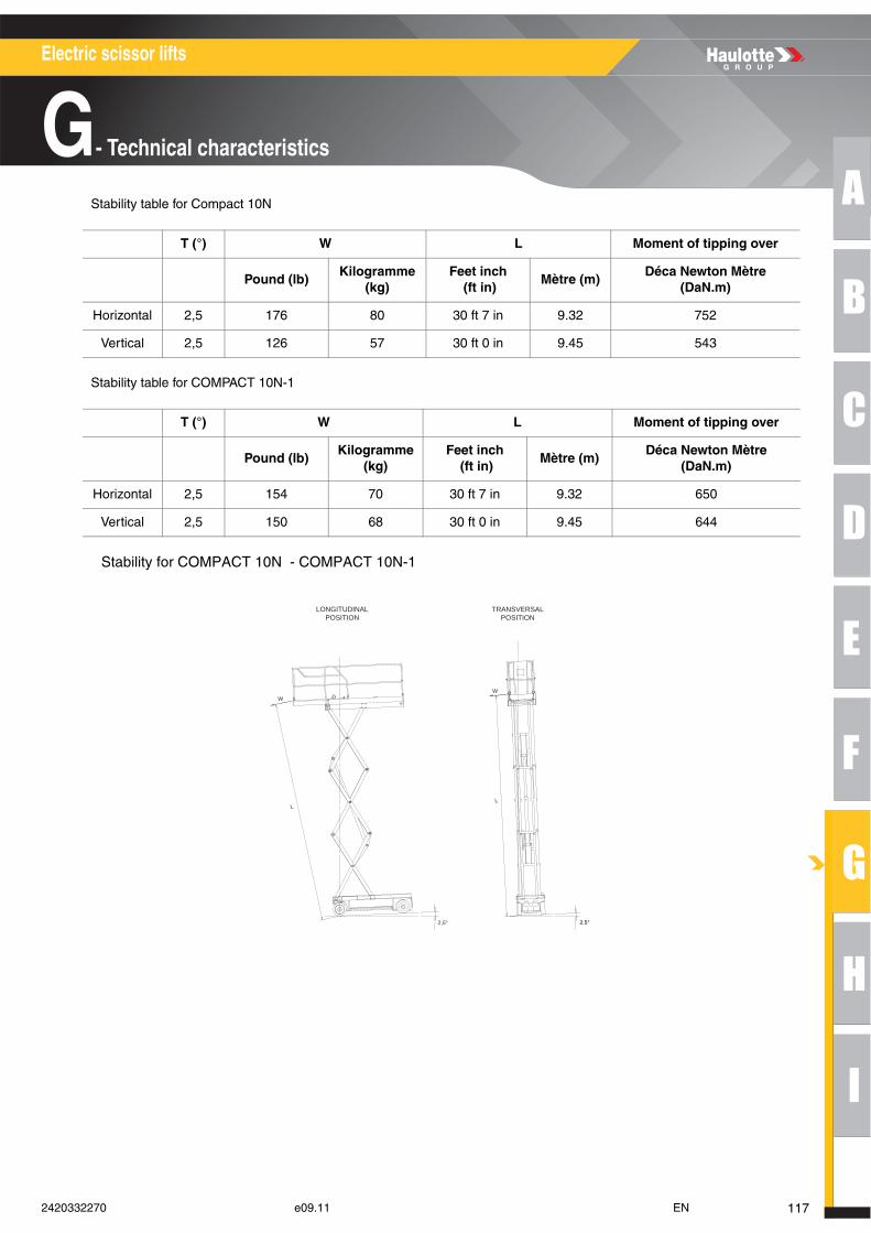
A
B
C
D
E
F
G
H
I
Electric scissor lifts
G- Technical characteristics
Stability table for Compact 10N
Stability table for COMPACT 10N-1
Stability for COMPACT 10N - COMPACT 10N-1
T (°) W L Moment of tipping over
Pound (lb)Kilogramme
(kg)Feet inch
(ft in)Mètre (m)
Déca Newton Mètre (DaN.m)
Horizontal 2,5 176 80 30 ft 7 in 9.32 752
Vertical 2,5 126 57 30 ft 0 in 9.45 543
T (°) W L Moment of tipping over
Pound (lb)Kilogramme
(kg)Feet inch
(ft in)Mètre (m)
Déca Newton Mètre (DaN.m)
Horizontal 2,5 154 70 30 ft 7 in 9.32 650
Vertical 2,5 150 68 30 ft 0 in 9.45 644
W
L
2,5°
W
L
3,5°2.5°
LONGITUDINALPOSITION
TRANSVERSALPOSITION
1172420332270 e09.11 EN
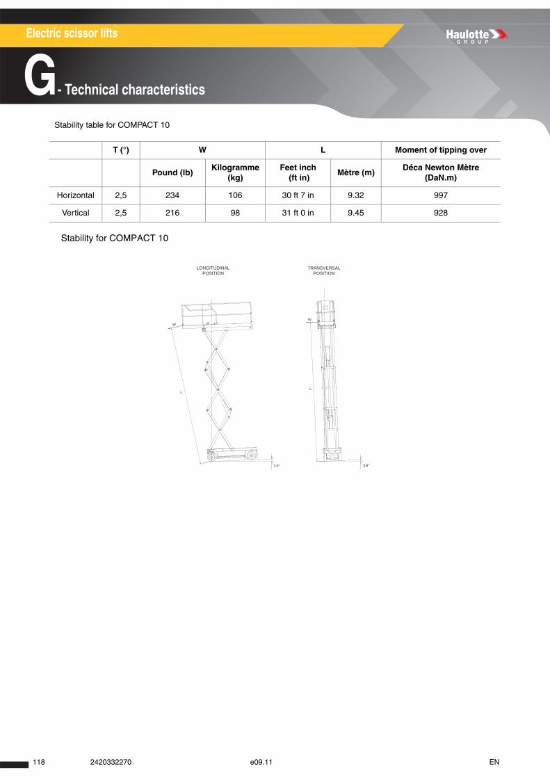
Electric scissor lifts
G- Technical characteristics
Stability table for COMPACT 10
Stability for COMPACT 10
T (°) W L Moment of tipping over
Pound (lb)Kilogramme
(kg)Feet inch
(ft in)Mètre (m)
Déca Newton Mètre (DaN.m)
Horizontal 2,5 234 106 30 ft 7 in 9.32 997
Vertical 2,5 216 98 31 ft 0 in 9.45 928
W
L
2,5°
W
L
3,5°2.5°
LONGITUDINALPOSITION
TRANSVERSALPOSITION
118 2420332270 e09.11 EN
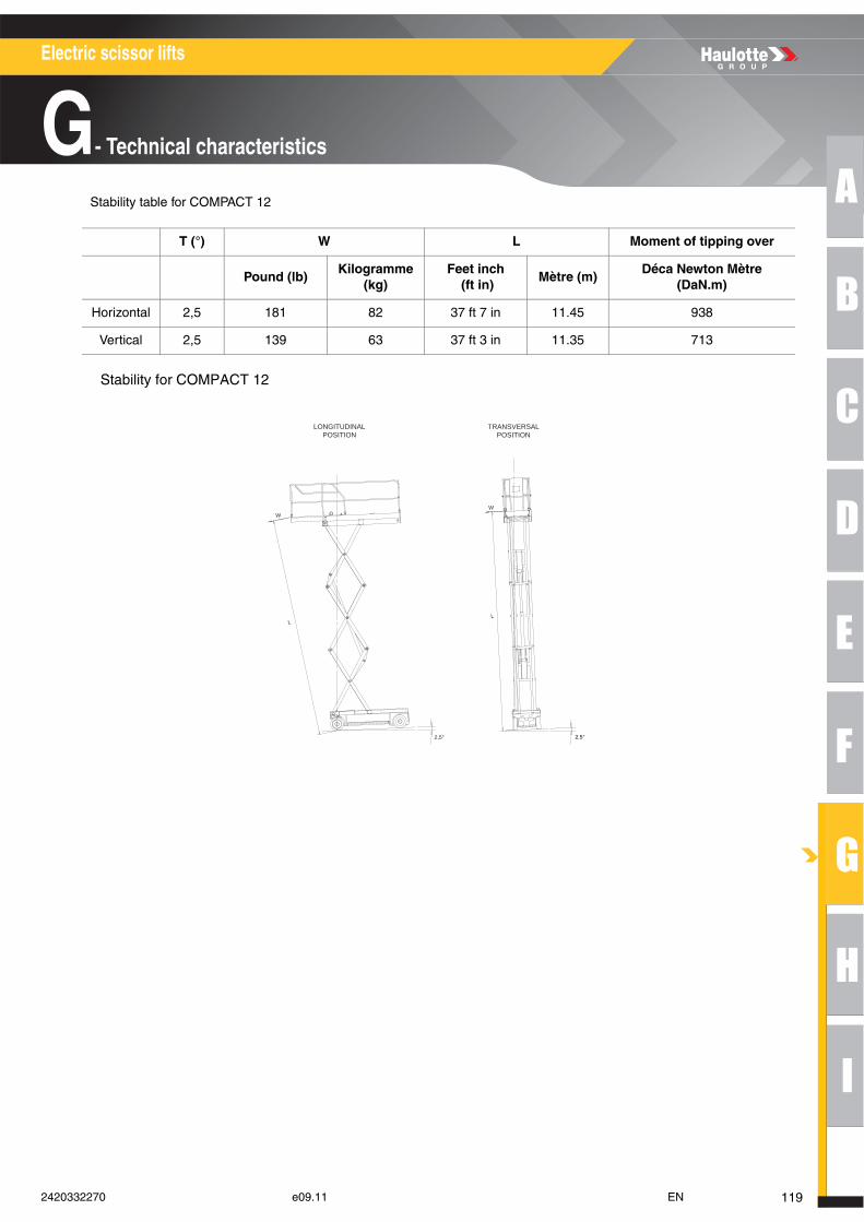
A
B
C
D
E
F
G
H
I
Electric scissor lifts
G- Technical characteristics
Stability table for COMPACT 12
Stability for COMPACT 12
T (°) W L Moment of tipping over
Pound (lb)Kilogramme
(kg)Feet inch
(ft in)Mètre (m)
Déca Newton Mètre (DaN.m)
Horizontal 2,5 181 82 37 ft 7 in 11.45 938
Vertical 2,5 139 63 37 ft 3 in 11.35 713
W
L
2,5°
W
L
3,5°2.5°
LONGITUDINALPOSITION
TRANSVERSALPOSITION
1192420332270 e09.11 EN
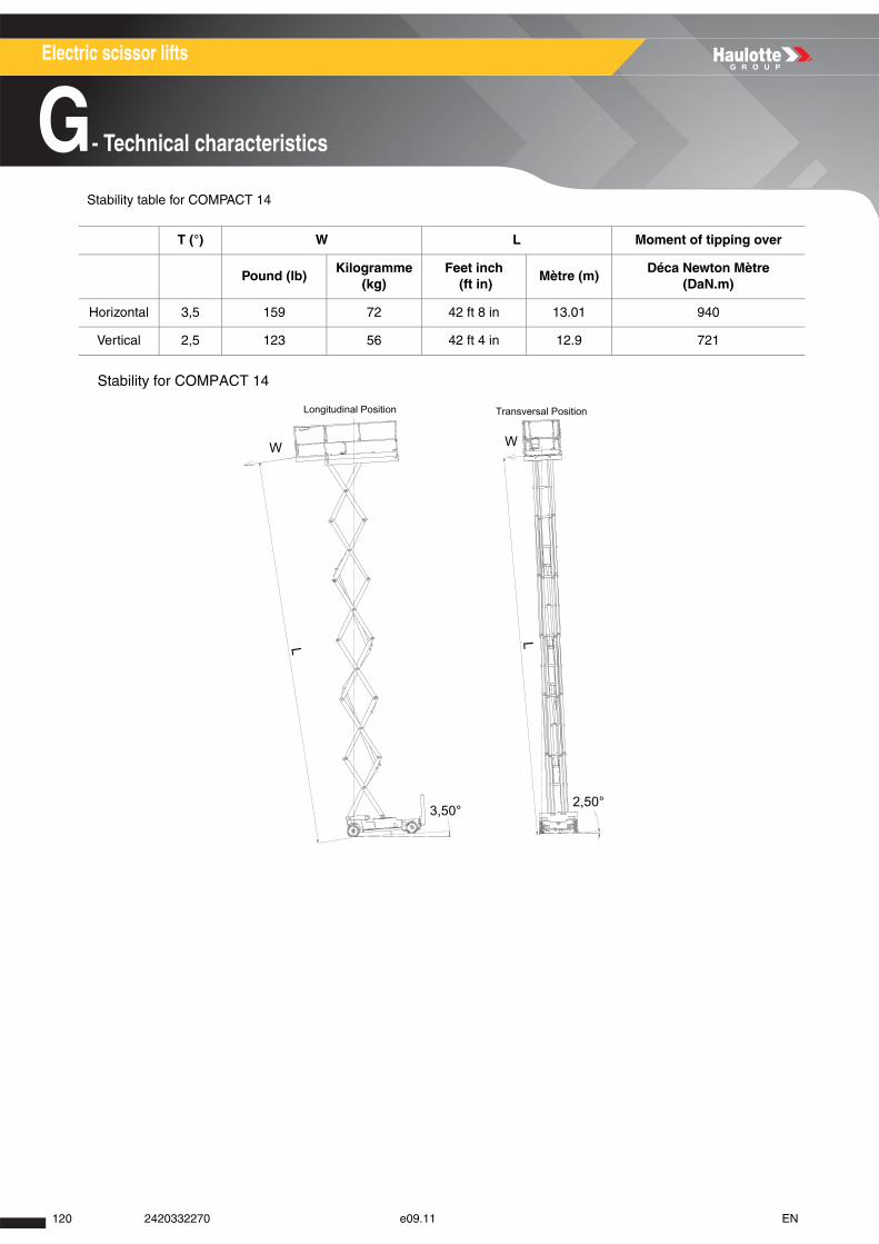
Electric scissor lifts
G- Technical characteristics
Stability table for COMPACT 14
Stability for COMPACT 14
T (°) W L Moment of tipping over
Pound (lb)Kilogramme
(kg)Feet inch
(ft in)Mètre (m)
Déca Newton Mètre (DaN.m)
Horizontal 3,5 159 72 42 ft 8 in 13.01 940
Vertical 2,5 123 56 42 ft 4 in 12.9 721
120 2420332270 e09.11 EN

A
B
C
D
E
F
G
H
I
Electric scissor lifts
G- Technical characteristics
Stability table for OPTIMUM 6
Stability for OPTIMUM 6
T (°) W L Moment of tipping over
Pound (lb)Kilogramme
(kg)Feet inch
(ft in)Mètre (m)
Déca Newton Mètre (DaN.m)
Horizontal 2,5 159 72 18 ft 4 in 5.60 404
Vertical 2,5 130 59 17 ft 10 in 5.44 321
2,5°
L
W
LONGITUDINALPOSITION
TRANSVERSALPOSITION
W
L
2,5°
1212420332270 e09.11 EN
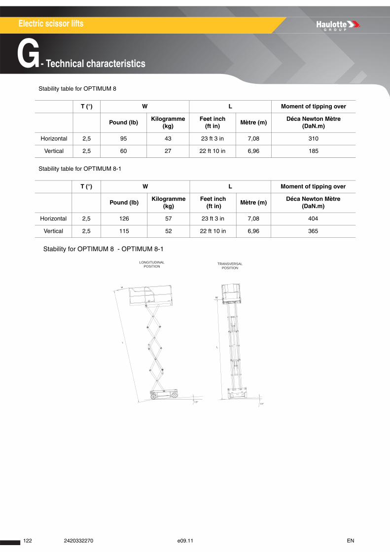
Electric scissor lifts
G- Technical characteristics
Stability table for OPTIMUM 8
Stability table for OPTIMUM 8-1
Stability for OPTIMUM 8 - OPTIMUM 8-1
T (°) W L Moment of tipping over
Pound (lb)Kilogramme
(kg)Feet inch
(ft in)Mètre (m)
Déca Newton Mètre (DaN.m)
Horizontal 2,5 95 43 23 ft 3 in 7,08 310
Vertical 2,5 60 27 22 ft 10 in 6,96 185
T (°) W L Moment of tipping over
Pound (lb)Kilogramme
(kg)Feet inch
(ft in)Mètre (m)
Déca Newton Mètre (DaN.m)
Horizontal 2,5 126 57 23 ft 3 in 7,08 404
Vertical 2,5 115 52 22 ft 10 in 6,96 365
2,5°
L
W
LONGITUDINALPOSITION
TRANSVERSALPOSITION
W
L
2,5°
122 2420332270 e09.11 EN
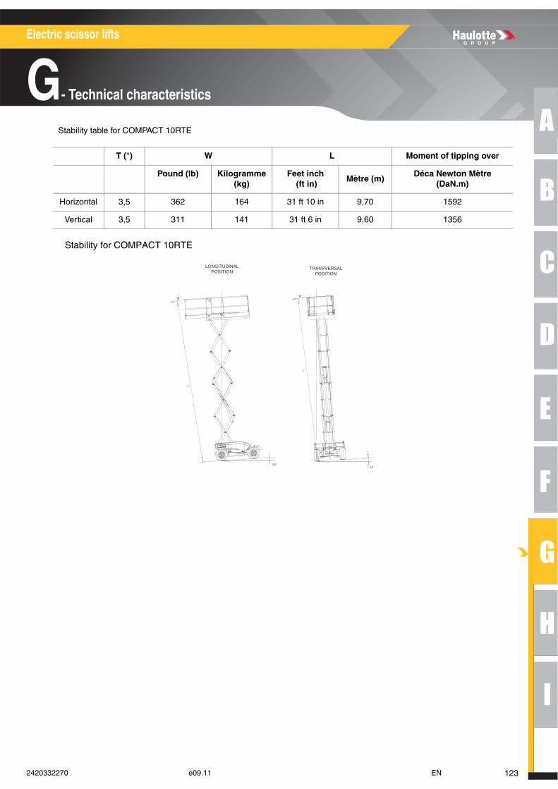
A
B
C
D
E
F
G
H
I
Electric scissor lifts
G- Technical characteristics
Stability table for COMPACT 10RTE
Stability for COMPACT 10RTE
T (°) W L Moment of tipping over
Pound (lb) Kilogramme (kg)
Feet inch (ft in)
Mètre (m)Déca Newton Mètre
(DaN.m)
Horizontal 3,5 362 164 31 ft 10 in 9,70 1592
Vertical 3,5 311 141 31 ft 6 in 9,60 1356
L
L
WW
LONGITUDINALPOSITION
TRANSVERSALPOSITION
3,53,5
1232420332270 e09.11 EN
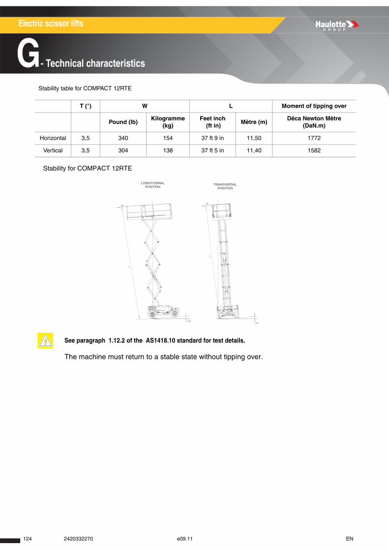
Electric scissor lifts
G- Technical characteristics
Stability table for COMPACT 12RTE
Stability for COMPACT 12RTE
The machine must return to a stable state without tipping over.
T (°) W L Moment of tipping over
Pound (lb)Kilogramme
(kg)Feet inch
(ft in)Mètre (m)
Déca Newton Mètre (DaN.m)
Horizontal 3,5 340 154 37 ft 9 in 11,50 1772
Vertical 3,5 304 138 37 ft 5 in 11,40 1582
See paragraph 1.12.2 of the AS1418.10 standard for test details.
L
L
WW
LONGITUDINALPOSITION
TRANSVERSALPOSITION
3,53,5
124 2420332270 e09.11 EN
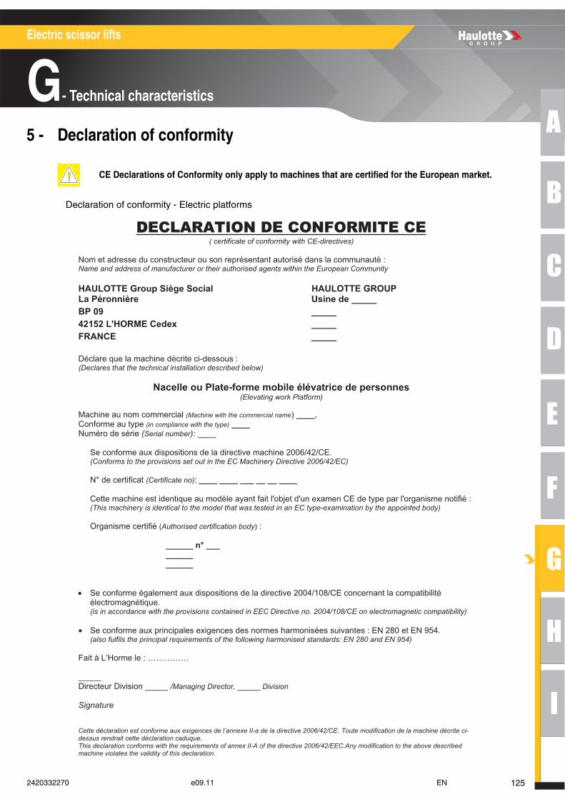
A
B
C
D
E
F
G
H
I
Electric scissor lifts
G- Technical characteristics
5 - Declaration of conformity
Declaration of conformity - Electric platforms
CE Declarations of Conformity only apply to machines that are certified for the European market.
DDECLARATION DE CONFORMITE CE( certificate of conformity with CE-directives)
Nom et adresse du constructeur ou son représentant autorisé dans la communauté : Name and address of manufacturer or their authorised agents within the European Community
PUORG ETTOLUAH laicoS egèiS puorG ETTOLUAHLa Péronnière Usine de _____ BP 09 _____ 42152 L'HORME Cedex _____ FRANCE _____
Déclare que la machine décrite ci-dessous : (Declares that the technical installation described below)
Nacelle ou Plate-forme mobile élévatrice de personnes (Elevating work Platform)
Machine au nom commercial (Machine with the commercial name) ____,Conforme au type (in compliance with the type) ____Numéro de série (Serial number): ____
Se conforme aux dispositions de la directive machine 2006/42/CE. (Conforms to the provisions set out in the EC Machinery Directive 2006/42/EC)
N° de certificat (Certificate no): ____ ____ ___ __ __ ____
Cette machine est identique au modèle ayant fait l'objet d'un examen CE de type par l'organisme notifié : (This machinery is identical to the model that was tested in an EC type-examination by the appointed body)
Organisme certifié (Authorised certification body) :
______ n° ___ ______ ______
• Se conforme également aux dispositions de la directive 2004/108/CE concernant la compatibilité électromagnétique. (is in accordance with the provisions contained in EEC Directive no. 2004/108/CE on electromagnetic compatibility)
• Se conforme aux principales exigences des normes harmonisées suivantes : EN 280 et EN 954. (also fulfils the principal requirements of the following harmonised standards: EN 280 and EN 954)
Fait à L’Horme le : ……………
_____ Directeur Division _____ /Managing Director, _____ Division
Signature
Cette déclaration est conforme aux exigences de l’annexe II-a de la directive 2006/42/CE. Toute modification de la machine décrite ci-dessus rendrait cette déclaration caduque. This declaration conforms with the requirements of annex II-A of the directive 2006/42/EEC.Any modification to the above describedmachine violates the validity of this declaration.
1252420332270 e09.11 EN
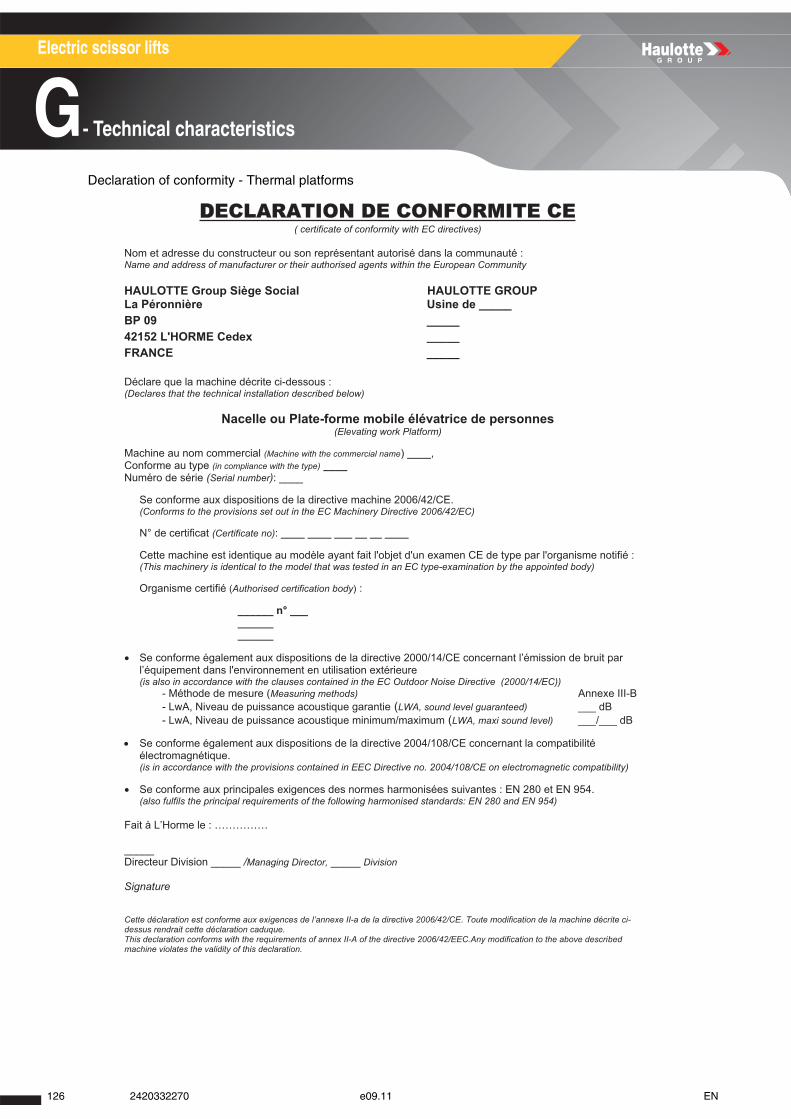
Electric scissor lifts
G- Technical characteristics
Declaration of conformity - Thermal platforms
DDECLARATION DE CONFORMITE CE( certificate of conformity with EC directives)
Nom et adresse du constructeur ou son représentant autorisé dans la communauté : Name and address of manufacturer or their authorised agents within the European Community
PUORG ETTOLUAH laicoS egèiS puorG ETTOLUAHLa Péronnière Usine de _____ BP 09 _____ 42152 L'HORME Cedex _____ FRANCE _____
Déclare que la machine décrite ci-dessous : (Declares that the technical installation described below)
Nacelle ou Plate-forme mobile élévatrice de personnes (Elevating work Platform)
Machine au nom commercial (Machine with the commercial name) ____,Conforme au type (in compliance with the type) ____Numéro de série (Serial number): ____
Se conforme aux dispositions de la directive machine 2006/42/CE. (Conforms to the provisions set out in the EC Machinery Directive 2006/42/EC)
N° de certificat (Certificate no): ____ ____ ___ __ __ ____
Cette machine est identique au modèle ayant fait l'objet d'un examen CE de type par l'organisme notifié : (This machinery is identical to the model that was tested in an EC type-examination by the appointed body)
Organisme certifié (Authorised certification body) :
______ n° ___ ______ ______
• Se conforme également aux dispositions de la directive 2000/14/CE concernant l’émission de bruit par l’équipement dans l'environnement en utilisation extérieure (is also in accordance with the clauses contained in the EC Outdoor Noise Directive (2000/14/EC))
- Méthode de mesure (Measuring methods) Annexe III-B - LwA, Niveau de puissance acoustique garantie (LWA, sound level guaranteed) ___ dB - LwA, Niveau de puissance acoustique minimum/maximum (LWA, maxi sound level) ___/___ dB
• Se conforme également aux dispositions de la directive 2004/108/CE concernant la compatibilité électromagnétique. (is in accordance with the provisions contained in EEC Directive no. 2004/108/CE on electromagnetic compatibility)
• Se conforme aux principales exigences des normes harmonisées suivantes : EN 280 et EN 954. (also fulfils the principal requirements of the following harmonised standards: EN 280 and EN 954)
Fait à L’Horme le : ……………
_____ Directeur Division _____ /Managing Director, _____ Division
Signature
Cette déclaration est conforme aux exigences de l’annexe II-a de la directive 2006/42/CE. Toute modification de la machine décrite ci-dessus rendrait cette déclaration caduque. This declaration conforms with the requirements of annex II-A of the directive 2006/42/EEC.Any modification to the above describedmachine violates the validity of this declaration.
126 2420332270 e09.11 EN
A
B
C
D
E
F
G
H
I
Electric scissor lifts
H- Intervention register
Intervention register1 - Intervention register
In order to benefit from the HAULOTTE® guarantee, each maintenance or repair operation must beentered in the INTERVENTION REGISTER, which can be found at the end of the maintenance bookdelivered with your machine.
Intervention register
A
B
C
D
E
F
G
H
I
H - REGISTRE D’INTERVENTION
REGISTRE D’INTERVENTION HAULOTTE SERVICE
Date Nature de l’intervention Nbre heures IntervenantN° interventionHaulotte service
MODELE
1272420332270 e09.11 EN

Electric scissor lifts
H- Intervention register
128 2420332270 e09.11 EN