lift technology
TRANSCRIPT
LIFT TECHNOLOGY
GB Instruction Manual COMBIVERT F5-LiftVersion 2.2
Mat.No. Rev.00F5LEB-K220 1D

2
GB - 3
1. Introduction ......................................................................................................................41.1 Preface ............................................................................................................................................... 41.2 Product description .......................................................................................................................... 41.3 Safety and Operating Instructions .................................................................................................. 5
2. Overview of control connections ...................................................................................62.1 Housing sizes D…E .......................................................................................................................... 62.2 Housing sizes G…U .......................................................................................................................... 62.3 Motor encoder connection X3A ....................................................................................................... 72.3.1 Incremental encoder interface ............................................................................................................ 72.3.2 SIN/COS encoder interface ................................................................................................................ 72.3.3 Resolver encoder interface ................................................................................................................. 72.3.4 Hiperface encoder interface ................................................................................................................ 82.3.5 EnDat encoder interface ..................................................................................................................... 82.3.6 UVW encoder interface ....................................................................................................................... 82.3.7 HTL encoder interface 0...30 V with differential signals ...................................................................... 82.3.8 HTL encoder interface without differential signals .............................................................................. 92.3.9 BISS encoder interface ....................................................................................................................... 92.4 Lift shaft encoder connection X3B.................................................................................................. 92.4.1 Incremental encoder output / incremental encoder input .................................................................... 92.4.2 SSI encoder interface ......................................................................................................................... 92.5 Wiringexamples/flowcharts ....................................................................................................... 102.5.1 Connection F5-Lift for binary-coded setpoint selection (factory setting) ........................................... 102.5.2 Connection F5-Lift input-coded setpoint selection ((Lb.05=2, Lb.12=0, Lb.13=1) ............................ 122.5.3 Connection F5-Lift for ogive travel with correction input (Lb.05=1, Lb.12=9) .................................. 142.5.4 Connection F5-Lift for UPS-run......................................................................................................... 162.6 Control terminal strip X2A ............................................................................................................. 192.7 Lift-Operator .................................................................................................................................... 202.7.1 Parameterizing interface X6B ........................................................................................................... 202.7.2 RS232/485-Interface X6C ................................................................................................................. 202.7.3 The Operator Panel .......................................................................................................................... 21
3. Parameter description...................................................................................................223.1 Overview of parameter groups ..................................................................................................... 223.2 Basic settings.................................................................................................................................. 223.3 Input of motor data ......................................................................................................................... 273.4 Adjustment of the motor encoder and shaft encoder ................................................................. 313.5 Lift functions ................................................................................................................................... 363.6 Positioning mode ............................................................................................................................ 443.7 Information, indications and measured values............................................................................ 483.8 Adjustment of analog inputs and outputs .................................................................................... 563.9 Adjustment of torque precontrol .................................................................................................. 60
4 Start-up ...........................................................................................................................624.1 Start-up of an asynchronous motor without speed encoder with gearbox. ............................ 624.2 Start-up of an asynchronous motor with speed encoder and gearbox ..................................... 634.3 Start-up of a synchronous motor with speed encoder without gearbox .................................. 64
5. Error diagnosis ..............................................................................................................65
6. Adjustment Speed Controller of F5 Lift with "speed jump" ......................................71
Table of Contents
GB - 4
Preface
1. Introduction1.1 Preface
We welcome you as a customer of the Karl E. Brinkmann GmbH and congratulate you to the aquisition of this product. You have chosen a product on highest technical standard. This manual as well as the specified hardware and software are developments of the Karl E. Brinkmann GmbH. Errors and ommissions excepted! The Karl E. Brinkmann GmbH have prepared the documentation, hardware and software to the best of their knowledge, however, no guarantee is given that the specifications will provide the efficiency aimed at by the user. The Karl E. Brinkmann GmbH reserves the right to change the specifications without prior notification or further obligation. All rights reserved. The safety and warning instructions specified in this manual do not lay claim on completeness.
The pictograms used in this manual mean:
DangerWarningCaution
Attentionobserve atall costs
InformationHelpTip
1.2 Product descriptionThis instruction manual describes the frequency inverter series KEB COMBIVERT F5 for lift drives. This series convinces through the special adaption of the operation to the requirements of lift drives. The lift functions are available only in connection with the lift operator (part number 00.F5.060-200C software version 2.2).
The power range of KEB COMBIVERT F5 for lift drives ranges from • 2.2…45 kW / 230 V class • 2.2…630 kW / 400 V class
The designs are available in following variants:• heat sink for control cabinet installation (standard)• heat sink for control cabinet cutout (through-mount version)• without heat sink for customer-specific cooling systems (Flat-Rear)
GB - 5
Important, absolutely read
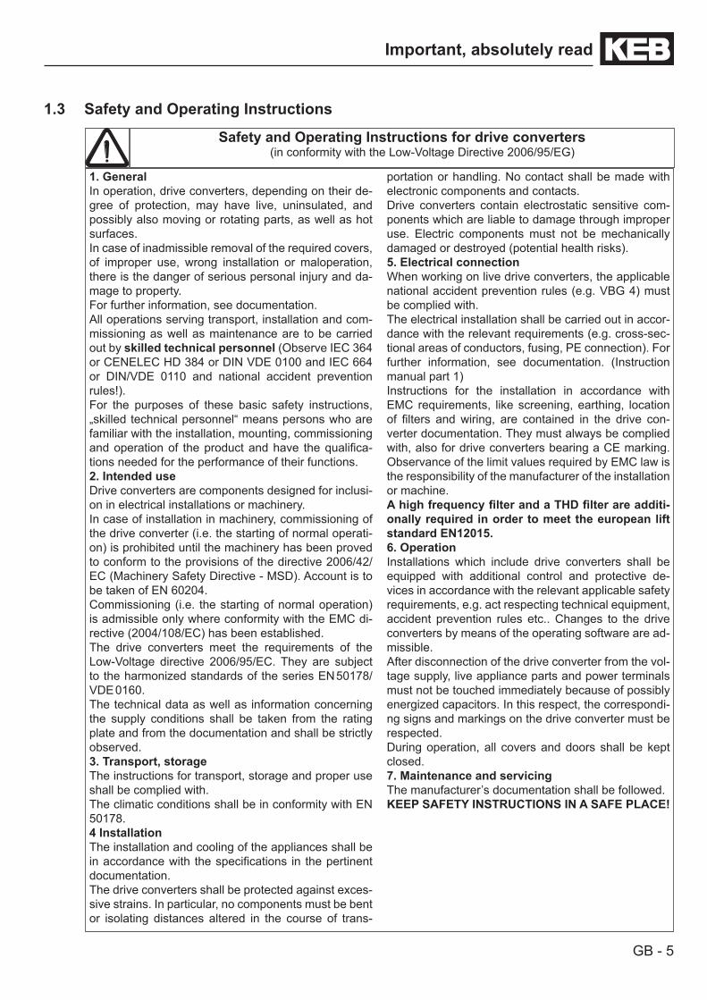
1.3 Safety and Operating Instructions
Safety and Operating Instructions for drive converters(in conformity with the Low-Voltage Directive 2006/95/EG)
1. GeneralIn operation, drive converters, depending on their de-gree of protection, may have live, uninsulated, and possibly also moving or rotating parts, as well as hot surfaces.In case of inadmissible removal of the required covers, of improper use, wrong installation or maloperation, there is the danger of serious personal injury and da-mage to property.For further information, see documentation.All operations serving transport, installation and com-missioning as well as maintenance are to be carried out by skilled technical personnel (Observe IEC 364 or CENELEC HD 384 or DIN VDE 0100 and IEC 664 or DIN/VDE 0110 and national accident prevention rules!).For the purposes of these basic safety instructions, „skilled technical personnel“ means persons who are familiar with the installation, mounting, commissioning and operation of the product and have the qualifica-tions needed for the performance of their functions.2. Intended useDrive converters are components designed for inclusi-on in electrical installations or machinery.In case of installation in machinery, commissioning of the drive converter (i.e. the starting of normal operati-on) is prohibited until the machinery has been proved to conform to the provisions of the directive 2006/42/EC (Machinery Safety Directive - MSD). Account is to be taken of EN 60204.Commissioning (i.e. the starting of normal operation) is admissible only where conformity with the EMC di-rective (2004/108/EC) has been established.The drive converters meet the requirements of the Low-Voltage directive 2006/95/EC. They are subject to the harmonized standards of the series EN 50178/ VDE 0160.The technical data as well as information concerning the supply conditions shall be taken from the rating plate and from the documentation and shall be strictly observed.3. Transport, storageThe instructions for transport, storage and proper use shall be complied with.The climatic conditions shall be in conformity with EN 50178.4 InstallationThe installation and cooling of the appliances shall be in accordance with the specifications in the pertinent documentation.The drive converters shall be protected against exces-sive strains. In particular, no components must be bent or isolating distances altered in the course of trans-
portation or handling. No contact shall be made with electronic components and contacts.Drive converters contain electrostatic sensitive com-ponents which are liable to damage through improper use. Electric components must not be mechanically damaged or destroyed (potential health risks).5. Electrical connectionWhen working on live drive converters, the applicable national accident prevention rules (e.g. VBG 4) must be complied with.The electrical installation shall be carried out in accor-dance with the relevant requirements (e.g. cross-sec-tional areas of conductors, fusing, PE connection). For further information, see documentation. (Instruction manual part 1) Instructions for the installation in accordance with EMC requirements, like screening, earthing, location of filters and wiring, are contained in the drive con-verter documentation. They must always be complied with, also for drive converters bearing a CE marking. Observance of the limit values required by EMC law is the responsibility of the manufacturer of the installation or machine.AhighfrequencyfilterandaTHDfilterareadditi-onally required in order to meet the european lift standard EN12015.6. OperationInstallations which include drive converters shall be equipped with additional control and protective de-vices in accordance with the relevant applicable safety requirements, e.g. act respecting technical equipment, accident prevention rules etc.. Changes to the drive converters by means of the operating software are ad-missible.After disconnection of the drive converter from the vol-tage supply, live appliance parts and power terminals must not be touched immediately because of possibly energized capacitors. In this respect, the correspondi-ng signs and markings on the drive converter must be respected. During operation, all covers and doors shall be kept closed.7. Maintenance and servicingThe manufacturer’s documentation shall be followed.KEEP SAFETY INSTRUCTIONS IN A SAFE PLACE!

GB - 6
Description of the Unit
2. Overview of Control Connections2.1 Housing sizes D…E
Notfor PC
STOPSPEED
FUNC.
F/R START
ENTER
COMBIVERT
X6B
X6C
X6D
Lift operator (00.F5.060-200C)
HSP5 interface X6B
RS232/485 interface X6D
Control terminal strip X2A
Lift shaft encoding X3B
Motor encoder X3A
2.2 Housing size G…U
Die Kondensatorentl
zeit betrÌgt 5 min.!Ein Fehlerstromschu
schalter ist als allei
SchutzmaBnahme ni
zulÌssig!
Warnung:
STOPSPEED
FUNC.
F/R START
ENTER
COMBIVERT
X6B
X6C
X6D
Lift operator (00.F5.060-200C)
HSP5 interface X6B
RS232/485 interface X6D
Lift shaft encoding X3B
Motor encoder X3A
Control terminal strip X2A
Observe maximum width of the connectors for X3A and X3B !

GB - 7
Description of the Unit
2.3 Motor encoder connection X3AThe connection of the motor encoder is done on socket X3A. Which of the encoders can be connected depends on the installed encoder interface and is displayed in LC.11.
All encoder connectors may be connected / discon-nected only at switched off frequency inverter and switched off supply voltage.
X3A
5 4 3 2 1
10 9 8 7 6
15 14 13 12 11
The frequency inverter monitores all encoder signals. If the encoder alarm is activated and no zero track is existent, connect N- with +5V (PIN12) and N+ with COM (PIN13).
The encoder alarm can be switched off with LC.03.
2.3.1 Incremental encoder interfacePIN Name Description3 A- Differential signal to A+4 B- Differential signal to B+8 A+ Incremental encoder track A9 B+ Incremental encoder track B11 +24 V Voltage output 20...30 V12 +5 V Voltage output 5 V, power supply for the encoders13 COM Reference potential for voltage supply14 N- Difference signal to N+ (if non-existent, assign with +5 V PIN12)15 N+ Zero track (if non-existent, assign with COM PIN13)- GND Connection for shielding at connector housing .
Internally directly connected with inverter earth.
2.3.2 SIN/COS encoder interfacePIN Name Description1 C- Differential signal to C+2 D- Differential signal to D+3 A- Differential signal to A+4 B- Differential signal to B+6 C+ Absolute track for initial position and angular calculation7 D+ Absolute track for initial position and angular calculation8 A+ Incremental signals A for counter and direction detection 9 B+ Incremental signals B for counter and direction detection
12 +5,25 V Power supply for encoder13 COM Reference potential for supply voltage14 -R Differential signal to zero track R+15 +R Zero track- GND Connection for shielding at connector housing .
Internally directly connected with inverter earth.
2.3.3 Resolver encoder interfacePIN Name Description3 SIN- Negated sinus signal 4 COS- Negated cosine signal5 REF- Negated field voltage output8 SIN+ Sinus signal9 COS+ Cosine signal
10 REF+ Field voltage output14 GND Connection for shielding of signal lines- GND Connection for shielding of the entire cable at the connector housing.
Internally directly connected with inverter earth.

GB - 8
Description of the Unit
2.3.4 Hiperface encoder interfacePIN Name Description3 REF_COS Signal offset to COS4 REF_SIN Signal offset to SIN8 COS+ Incremental signal COS for counter and direction detection9 SIN+ Incremental signal SIN for counter and direction detection
10 +7,5 V Power supply for encoder13 COM Reference potential for supply voltage14 Data- Data channel RS48515 Data+ Data channel RS485- GND Connection for shielding at connector housing .
Internally directly connected with inverter earth.
2.3.5 EnDat encoder interfacePIN Name Description3 A- Signal input A- (difference signal to A+)4 B- Signal input B- (difference signal to B+)6 Clock+ Clock signal RS4857 Clock- Clock signal RS4858 A+ Incremental signals A for counter and direction detection9 B+ Incremental signals B for counter and direction detection
12 +5,25 V Power supply for encoder13 COM Reference potential for supply voltage14 Data- Data channel RS48515 Data+ Data channel RS485- GND Connection for shielding at connector housing .
Internally directly connected with inverter earth.
2.3.6 UVW encoder interfacePIN Name Description1 A+ Incremental signal A2 A- Differential signal to A+3 B+ Incremental signal B4 B- Differential signal to B+5 N+ Zero track6 N- Difference signal to zero track N+7 U+ Commutation signal U8 U- Differential signal to U+9 V+ Commutation signal V
10 V- Differential signal to V+11 W+ Commutation signal W12 W- Differential signal to W+13 5 V Voltage output 5V14 COM Reference potential for supply voltage15 - -- GND Connection for shielding at connector housing .
Internally directly connected with inverter earth.
2.3.7 HTL encoder interface 0...30 V with difference signalsPIN Name Description3 A- Differential signal to A+4 B- Differential signal to B+8 A+ HTL incremental encoder track A9 B+ HTL incremental encoder track B11 +24 V Voltage output 20...30 V12 +5 V Voltage output 5 V, power supply for the encoders13 COM Reference potential for voltage supply14 N- Differential signal to N+ (if nonexistent, assign with +5 V PIN12 )15 N+ HTL zero track (if non-existent, assign with 0 V PIN13)- GND Connection for shielding at connector housing .
Internally directly connected with inverter earth.
GB - 9
Description of the Unit
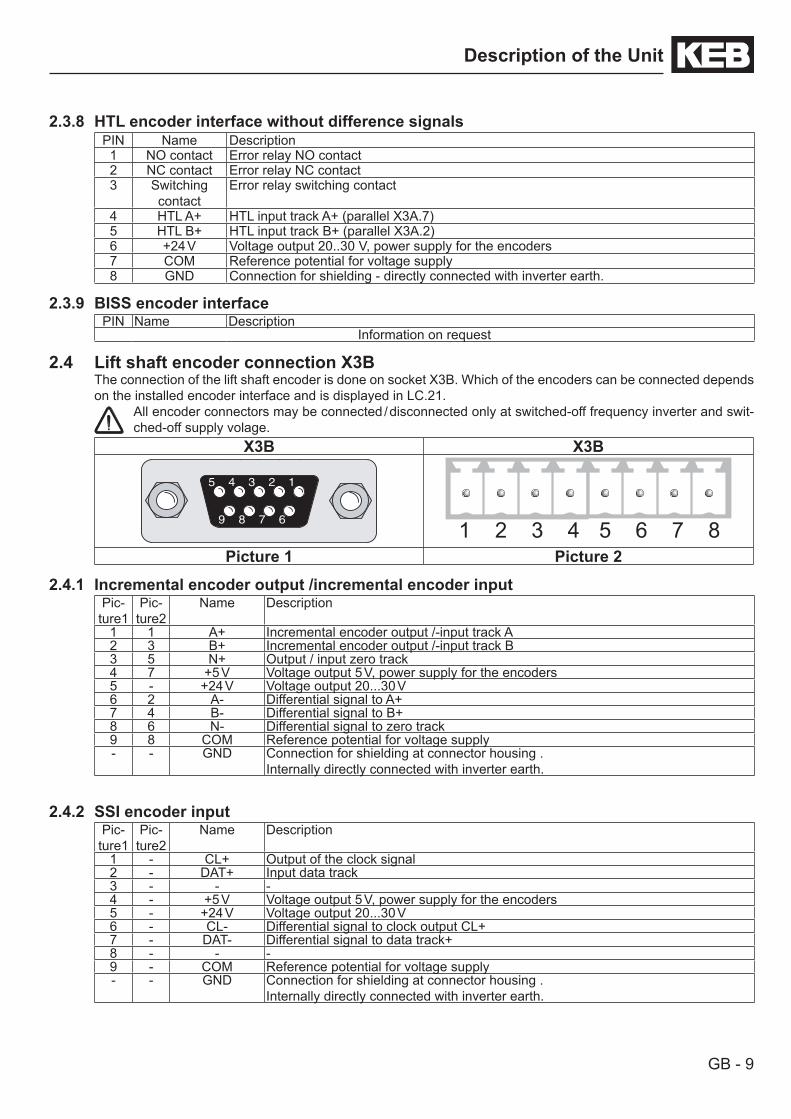
2.3.8 HTL encoder interface without difference signalsPIN Name Description1 NO contact Error relay NO contact2 NC contact Error relay NC contact3 Switching
contactError relay switching contact
4 HTL A+ HTL input track A+ (parallel X3A.7)5 HTL B+ HTL input track B+ (parallel X3A.2)6 +24 V Voltage output 20..30 V, power supply for the encoders7 COM Reference potential for voltage supply8 GND Connection for shielding - directly connected with inverter earth.
2.3.9 BISS encoder interfacePIN Name Description
Information on request
2.4 Lift shaft encoder connection X3BThe connection of the lift shaft encoder is done on socket X3B. Which of the encoders can be connected depends on the installed encoder interface and is displayed in LC.21.
All encoder connectors may be connected / disconnected only at switched-off frequency inverter and swit-ched-off supply volage.
X3B X3B5 4 3 2 1
9 8 7 6
5 4 3 2 1
9 8 7 6
Picture 1 Picture 2
2.4.1 Incremental encoder output /incremental encoder inputPic-
ture1Pic-
ture2Name Description
1 1 A+ Incremental encoder output /-input track A2 3 B+ Incremental encoder output /-input track B3 5 N+ Output / input zero track4 7 +5 V Voltage output 5 V, power supply for the encoders5 - +24 V Voltage output 20...30 V6 2 A- Differential signal to A+7 4 B- Differential signal to B+8 6 N- Differential signal to zero track9 8 COM Reference potential for voltage supply- - GND Connection for shielding at connector housing .
Internally directly connected with inverter earth.
2.4.2 SSI encoder inputPic-
ture1Pic-
ture2Name Description
1 - CL+ Output of the clock signal2 - DAT+ Input data track3 - - -4 - +5 V Voltage output 5 V, power supply for the encoders5 - +24 V Voltage output 20...30 V6 - CL- Differential signal to clock output CL+7 - DAT- Differential signal to data track+8 - - -9 - COM Reference potential for voltage supply- - GND Connection for shielding at connector housing .
Internally directly connected with inverter earth.
GB - 10
Description of the Unit
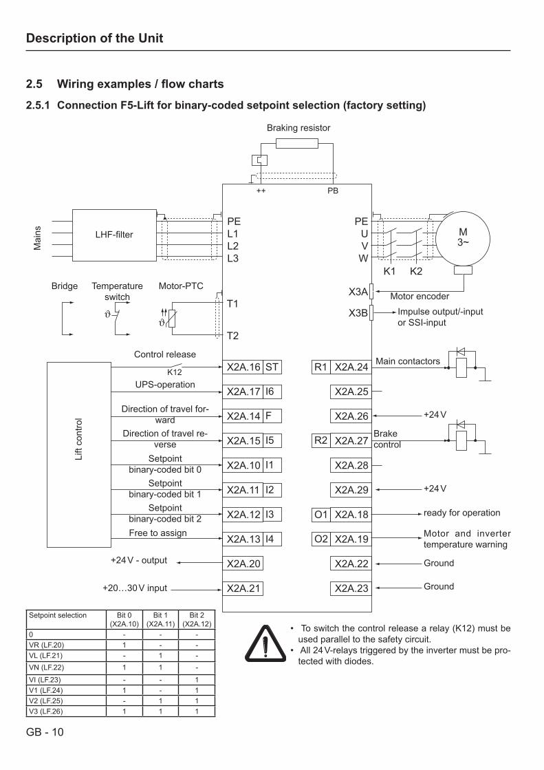
2.5 Wiringexamples/flowcharts
2.5.1 Connection F5-Lift for binary-coded setpoint selection (factory setting)
PE L1 L2 L3
PE U V W
M 3~
K1 K2
X3A
X3B T1
T2
X2A.16 X2A.17 X2A.14 X2A.15 X2A.10 X2A.11 X2A.12 X2A.13 X2A.20 X2A.21
X2A.24
X2A.25
X2A.26
X2A.27
X2A.28
X2A.29
X2A.18
X2A.19
X2A.22
X2A.23
K12
++ PB
ST
I6
R1
R2
F
I5
I1
O1
I2
I3
I4 O2
LHF-filter
Mai
ns
Braking resistor
Motor encoder
Impulse output/-inputor SSI-input
Main contactors
Brake control
+24 V
+24 V
ready for operation
Motor and inverter temperature warning
Ground
Ground
Motor-PTCTemperature switch
Bridge
Lift
cont
rol
UPS-operation
Direction of travel for-ward
Direction of travel re-verse
Setpoint binary-coded bit 0
Setpoint binary-coded bit 1
Setpoint binary-coded bit 2
+24 V - output
+20…30 V input
Setpoint selection Bit 0 (X2A.10)
Bit 1 (X2A.11)
Bit 2 (X2A.12)
0 - - -VR (LF.20) 1 - -VL (LF.21) - 1 -VN (LF.22) 1 1 -
VI (LF.23) - - 1V1 (LF.24) 1 - 1V2 (LF.25) - 1 1V3 (LF.26) 1 1 1
• To switch the control release a relay (K12) must be used parallel to the safety circuit.
• All 24 V-relays triggered by the inverter must be pro-tected with diodes.
Control release
Free to assign

GB - 11
Description of the Unit
Flow chart at factory setting
t1: The bit sample for the setpoint values and the direction of travel is set. Immediately after that the inverter sets the output for the main contactors.
t2: The control release (Start) is set by a relay parallel to the main contactor control. Thereupon the output phase check is executed.
t3: Upon successful output phase check the brake output is set. Thereupon the brake opening time runs out.Then the motor starts to turn.
t4: The rated speed is reset and switched over to leveling speed. t5: The leveling speed is reset and the stopping is initiated. t6: On reaching the speed 0 rpm the brake output is reset. Afterwards the brake engage time runs off.t7: The output for the main contactor is reset and thus also the control release and the direction of travel.
Generally the inverter switches the main contactors only in currentless condition.
t
t1 t3t2
t4 t5 t6 t7
v
Setpoint Bit 1 (X2A.11)
Setpoint Bit 0 (X2A.10)
Setpoint Bit 2 (X2A.12)
forward (X2A.14)
Start (X2A.16)
HS (X2A.24…26)
Brake (X2A.27…29)
GB - 12
Description of the Unit
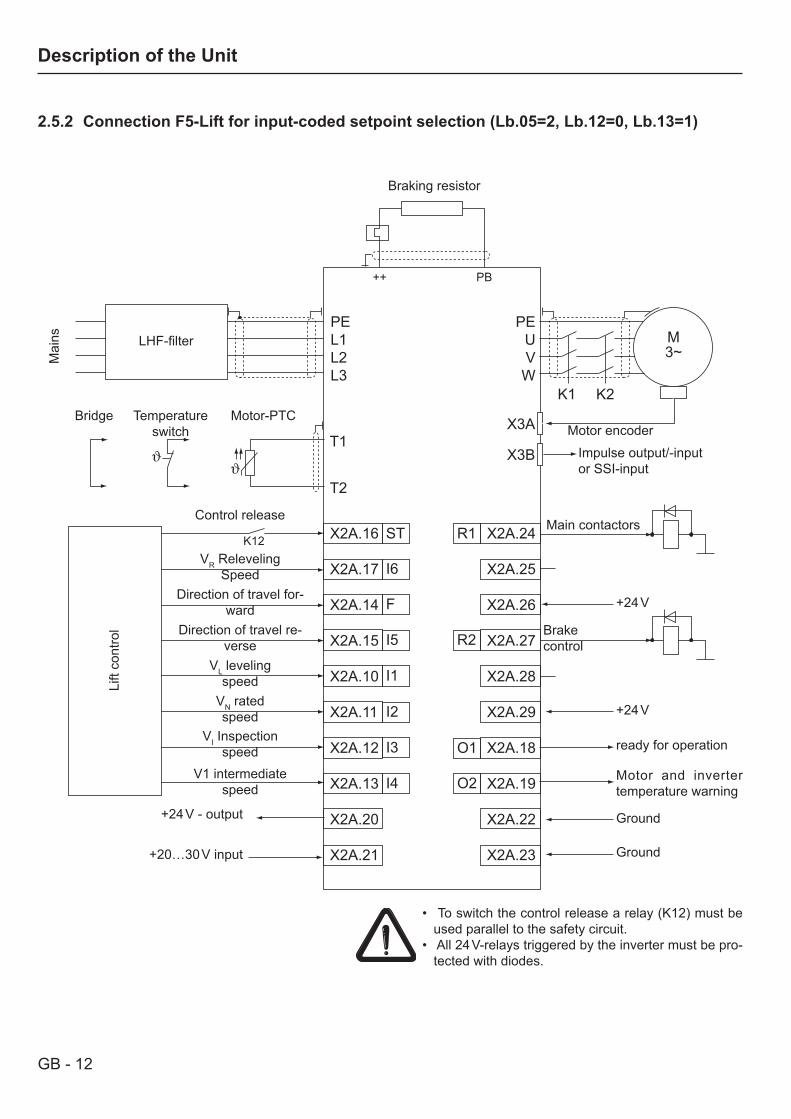
2.5.2 Connection F5-Lift for input-coded setpoint selection (Lb.05=2, Lb.12=0, Lb.13=1)
PE L1 L2 L3
PE U V W
M 3~
K1 K2
X3A
X3B T1
T2
X2A.16 X2A.17 X2A.14 X2A.15 X2A.10 X2A.11 X2A.12 X2A.13 X2A.20 X2A.21
X2A.24
X2A.25
X2A.26
X2A.27
X2A.28
X2A.29
X2A.18
X2A.19
X2A.22
X2A.23
K12
++ PB
ST
I6
R1
R2
F
I5
I1
O1
I2
I3
I4 O2
LHF-filter
Mai
ns
Braking resistor
Motor encoder
Impulse output/-inputor SSI-input
Main contactors
Brake control
+24 V
+24 V
ready for operation
Motor and inverter temperature warning
Ground
Ground
Motor-PTCTemperature switch
Bridge
Lift
cont
rol
VR RelevelingSpeed
Direction of travel for-ward
Direction of travel re-verse
VL levelingspeed
VN ratedspeed
VI Inspectionspeed
+24 V - output
+20…30 V input
• To switch the control release a relay (K12) must be used parallel to the safety circuit.
• All 24 V-relays triggered by the inverter must be pro-tected with diodes.
Control release
V1 intermediatespeed
GB - 13
Description of the Unit
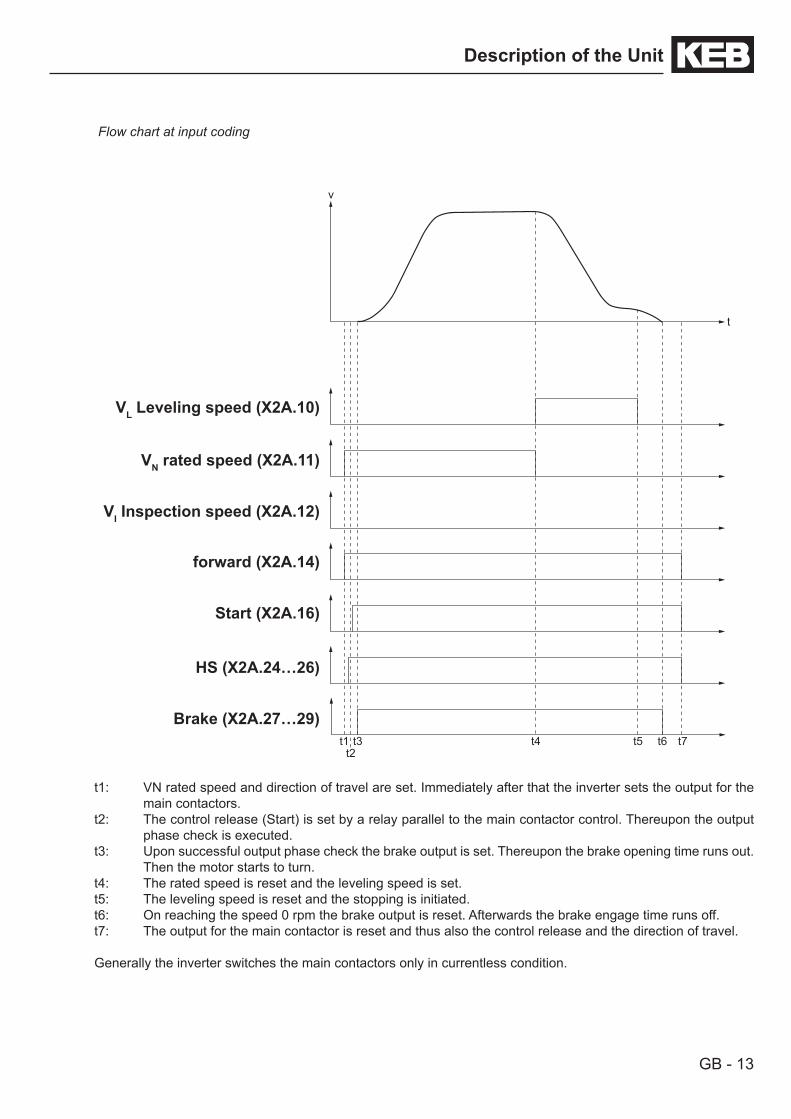
Flow chart at input coding
t1: VN rated speed and direction of travel are set. Immediately after that the inverter sets the output for the main contactors.
t2: The control release (Start) is set by a relay parallel to the main contactor control. Thereupon the output phase check is executed.
t3: Upon successful output phase check the brake output is set. Thereupon the brake opening time runs out. Then the motor starts to turn.
t4: The rated speed is reset and the leveling speed is set. t5: The leveling speed is reset and the stopping is initiated. t6: On reaching the speed 0 rpm the brake output is reset. Afterwards the brake engage time runs off.t7: The output for the main contactor is reset and thus also the control release and the direction of travel.
Generally the inverter switches the main contactors only in currentless condition.
t
t1 t3t2
t4 t5 t6 t7
v
VL Leveling speed (X2A.10)
VN rated speed (X2A.11)
VI Inspection speed (X2A.12)
forward (X2A.14)
Start (X2A.16)
HS (X2A.24…26)
Brake (X2A.27…29)

GB - 14
Description of the Unit
2.5.3 Connection F5-Lift for ogive travel with correction input (Lb.05=1, Lb.12=9)
PE L1 L2 L3
PE U V W
M 3~
K1 K2
X3A
X3B T1
T2
X2A.16 X2A.17 X2A.14 X2A.15 X2A.10 X2A.11 X2A.12 X2A.13 X2A.20 X2A.21
X2A.24
X2A.25
X2A.26
X2A.27
X2A.28
X2A.29
X2A.18
X2A.19
X2A.22
X2A.23
K12
++ PB
ST
I6
R1
R2
F
I5
I1
O1
I2
I3
I4 O2
LHF-filter
Mai
ns
Braking resistor
Motor encoder
Impulse output/-inputor SSI-input
Main contactors
Brake control
+24 V
+24 V
ready for operation
Motor and inverter temperature warning
Ground
Ground
Motor-PTCTemperature switch
Bridge
Lift
cont
rol
Correction input
Direction of travel for-ward
Direction of travel re-verse
Setpoint Bit0
Setpoint Bit1
Setpoint Bit2
+24 V - output
+20…30 V input
• To switch the control release a relay (K12) must be used parallel to the safety circuit.
• All 24 V-relays triggered by the inverter must be pro-tected with diodes.
Control release
Free to assign
GB - 15
Description of the Unit
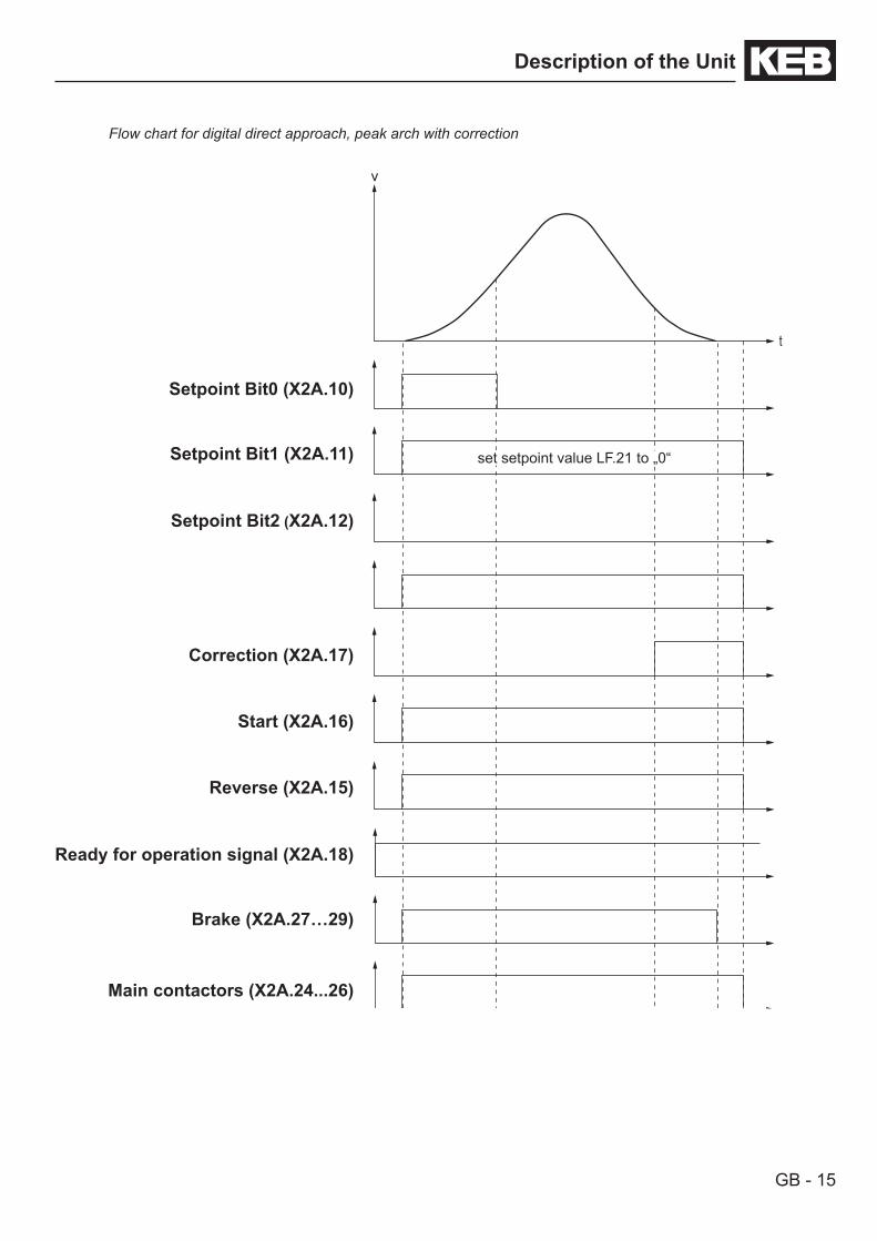
Flow chart for digital direct approach, peak arch with correction
t
v
Setpoint Bit0 (X2A.10)
Setpoint Bit1 (X2A.11)
Setpoint Bit2 (X2A.12)
Correction (X2A.17)
Start (X2A.16)
Reverse (X2A.15)
Ready for operation signal (X2A.18)
Brake (X2A.27…29)
Main contactors (X2A.24...26)
set setpoint value LF.21 to „0“
GB - 16
Description of the Unit
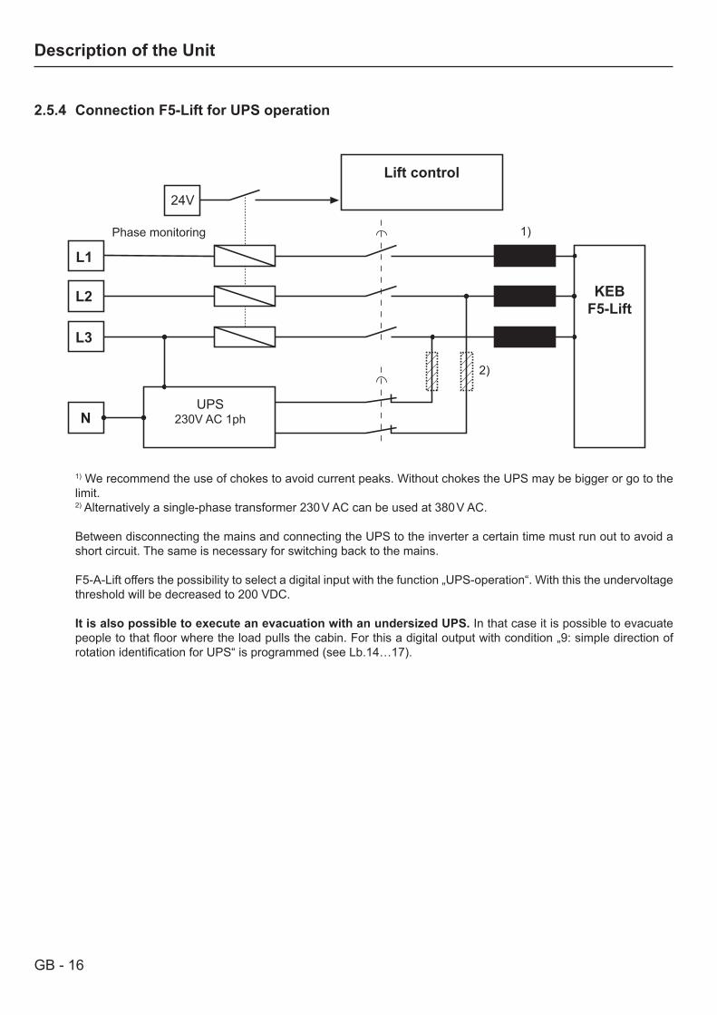
2.5.4 Connection F5-Lift for UPS operation
1) We recommend the use of chokes to avoid current peaks. Without chokes the UPS may be bigger or go to the limit.2) Alternatively a single-phase transformer 230 V AC can be used at 380 V AC.
Between disconnecting the mains and connecting the UPS to the inverter a certain time must run out to avoid a short circuit. The same is necessary for switching back to the mains.
F5-A-Lift offers the possibility to select a digital input with the function „UPS-operation“. With this the undervoltage threshold will be decreased to 200 VDC.
It is also possible to execute an evacuation with an undersized UPS. In that case it is possible to evacuate people to that floor where the load pulls the cabin. For this a digital output with condition „9: simple direction of rotation identification for UPS“ is programmed (see Lb.14…17).
Lift control
Phase monitoring
KEBF5-Lift
L1
L3
L2
N
24V
UPS230V AC 1ph
1)
2)
GB - 17
Description of the Unit
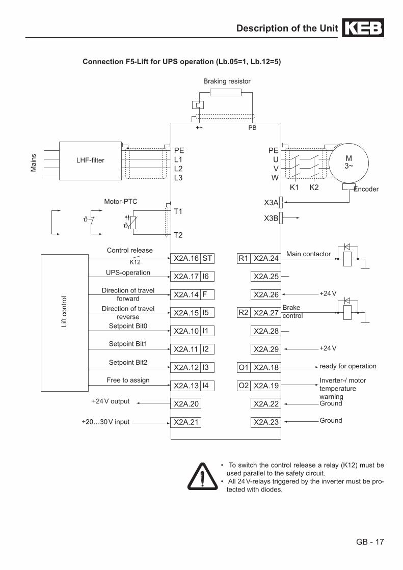
Connection F5-Lift for UPS operation (Lb.05=1, Lb.12=5)
PE L1 L2 L3
PE U V W
M 3~
K1 K2
X3A
X3B T1
T2
X2A.16 X2A.17 X2A.14 X2A.15 X2A.10 X2A.11 X2A.12 X2A.13 X2A.20 X2A.21
X2A.24
X2A.25
X2A.26
X2A.27
X2A.28
X2A.29
X2A.18
X2A.19
X2A.22
X2A.23
K12
++ PB
ST
I6
R1
R2
F
I5
I1
O1
I2
I3
I4 O2
LHF-filter
Mai
ns
Braking resistor
Encoder
Main contactor
Brakecontrol
+24 V
+24 V
ready for operation
Inverter-/ motor temperaturewarningGround
Ground
Motor-PTC
Lift
cont
rol
UPS-operation
Direction of travel forward
Free to assign
Direction of travel reverse
Setpoint Bit0
Setpoint Bit1
+24 V output
+20…30 V input
• To switch the control release a relay (K12) must be used parallel to the safety circuit.
• All 24 V-relays triggered by the inverter must be pro-tected with diodes.
Control release
Setpoint Bit2
GB - 18
Description of the Unit
t
v
t1t2
t3 t5t4
t6 t7
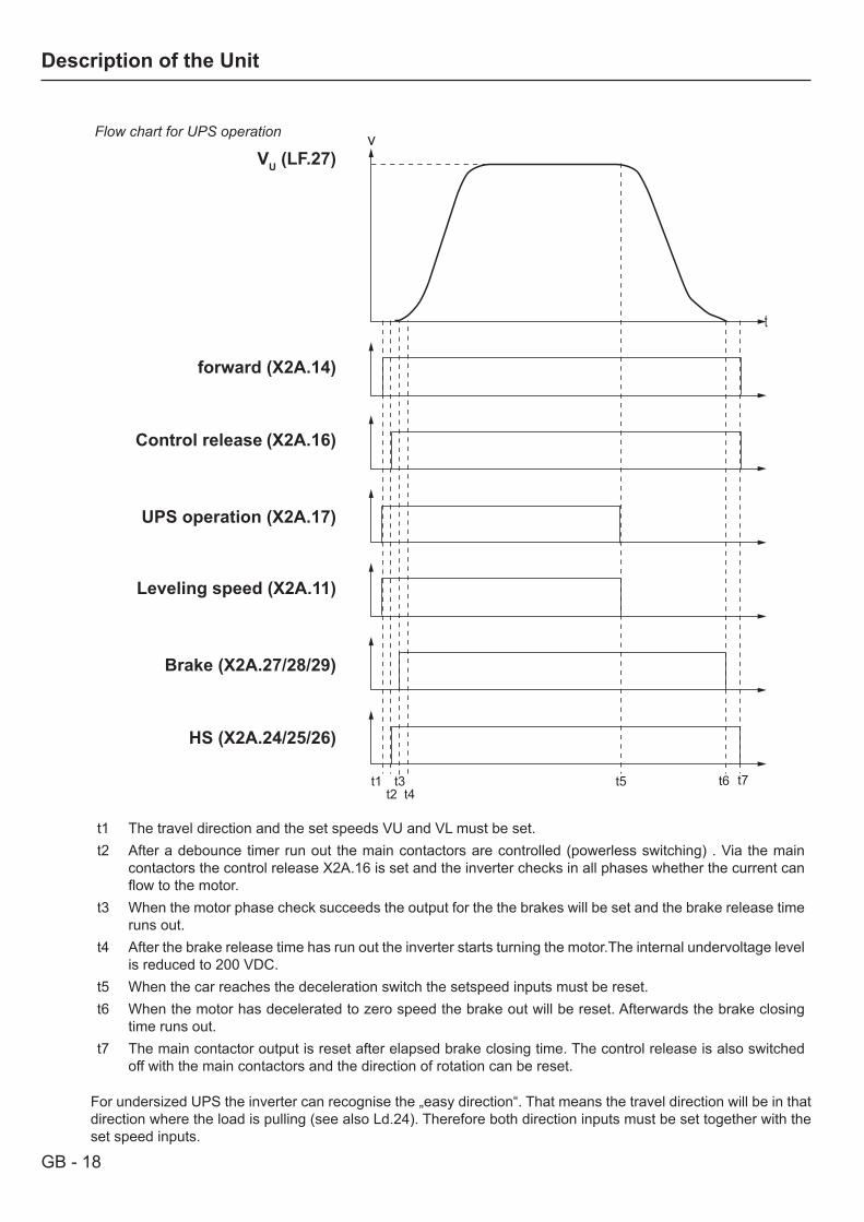
Flow chart for UPS operation
forward (X2A.14)
Control release (X2A.16)
Leveling speed (X2A.11)
Brake (X2A.27/28/29)
HS (X2A.24/25/26)
UPS operation (X2A.17)
VU (LF.27)
t1 The travel direction and the set speeds VU and VL must be set.t2 After a debounce timer run out the main contactors are controlled (powerless switching) . Via the main
contactors the control release X2A.16 is set and the inverter checks in all phases whether the current can flow to the motor.
t3 When the motor phase check succeeds the output for the the brakes will be set and the brake release time runs out.
t4 After the brake release time has run out the inverter starts turning the motor.The internal undervoltage level is reduced to 200 VDC.
t5 When the car reaches the deceleration switch the setspeed inputs must be reset.t6 When the motor has decelerated to zero speed the brake out will be reset. Afterwards the brake closing
time runs out.t7 The main contactor output is reset after elapsed brake closing time. The control release is also switched
off with the main contactors and the direction of rotation can be reset.
For undersized UPS the inverter can recognise the „easy direction“. That means the travel direction will be in that direction where the load is pulling (see also Ld.24). Therefore both direction inputs must be set together with the set speed inputs.
GB - 19
Description of the Unit
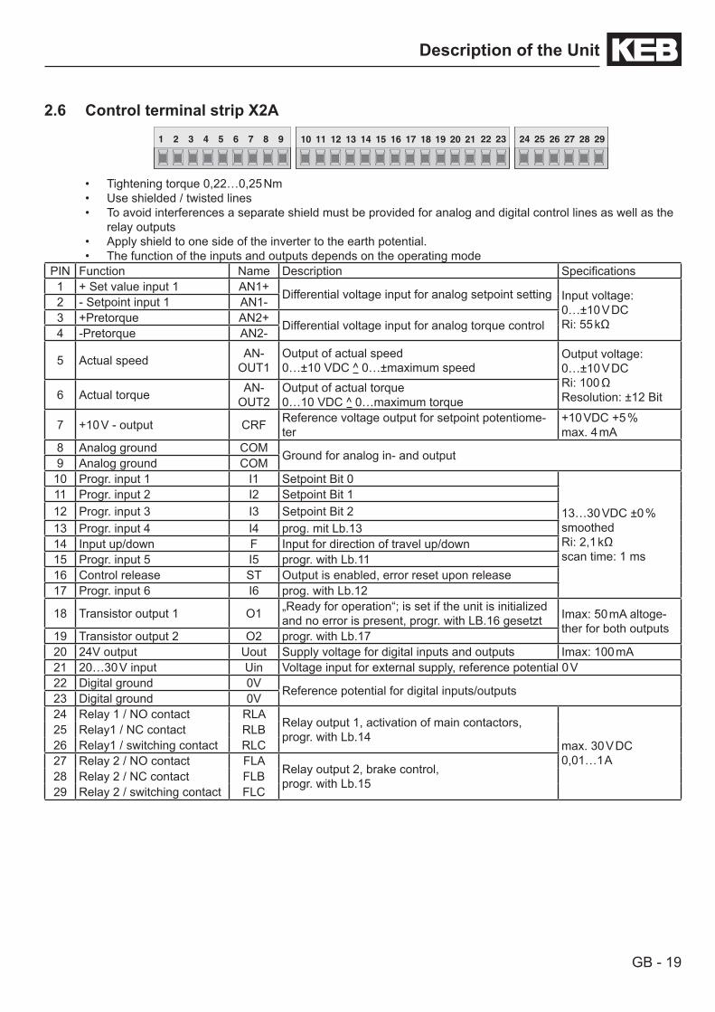
2.6 Control terminal strip X2A
Tightening torque 0,22…0,25 Nm• Use shielded / twisted lines• To avoid interferences a separate shield must be provided for analog and digital control lines as well as the • relay outputsApply shield to one side of the inverter to the earth potential.• The function of the inputs and outputs depends on the operating mode•
PIN Function Name Description Specifications1 + Set value input 1 AN1+ Differential voltage input for analog setpoint setting Input voltage:
0…±10 V DCRi: 55 kΩ
2 - Setpoint input 1 AN1-3 +Pretorque AN2+ Differential voltage input for analog torque control4 -Pretorque AN2-
5 Actual speed AN-OUT1
Output of actual speed0…±10 VDC ^ 0…±maximum speed
Output voltage:0…±10 V DCRi: 100 ΩResolution: ±12 Bit6 Actual torque AN-
OUT2Output of actual torque0…10 VDC ^ 0…maximum torque
7 +10 V - output CRF Reference voltage output for setpoint potentiome-ter
+10 VDC +5 % max. 4 mA
8 Analog ground COM Ground for analog in- and output9 Analog ground COM10 Progr. input 1 I1 Setpoint Bit 0
13…30 VDC ±0 % smoothedRi: 2,1 kΩscan time: 1 ms
11 Progr. input 2 I2 Setpoint Bit 112 Progr. input 3 I3 Setpoint Bit 213 Progr. input 4 I4 prog. mit Lb.1314 Input up/down F Input for direction of travel up/down 15 Progr. input 5 I5 progr. with Lb.1116 Control release ST Output is enabled, error reset upon release17 Progr. input 6 I6 prog. with Lb.12
18 Transistor output 1 O1 „Ready for operation“; is set if the unit is initialized and no error is present, progr. with LB.16 gesetzt Imax: 50 mA altoge-
ther for both outputs19 Transistor output 2 O2 progr. with Lb.1720 24V output Uout Supply voltage for digital inputs and outputs Imax: 100 mA21 20…30 V input Uin Voltage input for external supply, reference potential 0 V22 Digital ground 0V Reference potential for digital inputs/outputs23 Digital ground 0V24 Relay 1 / NO contact RLA
Relay output 1, activation of main contactors,progr. with Lb.14
max. 30 V DC0,01…1 A
25 Relay1 / NC contact RLB26 Relay1 / switching contact RLC27 Relay 2 / NO contact FLA
Relay output 2, brake control, progr. with Lb.1528 Relay 2 / NC contact FLB
29 Relay 2 / switching contact FLC
1 2 3 4 5 6 7 8 9 10 11 12 13 14 15 16 17 18 19 20 21 22 23 24 25 26 27 28 29
GB - 20
Description of the Unit
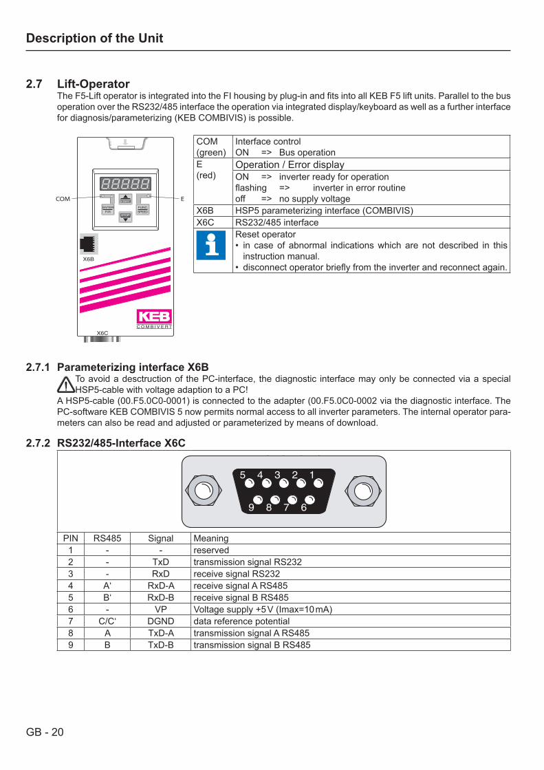
2.7 Lift-OperatorThe F5-Lift operator is integrated into the FI housing by plug-in and fits into all KEB F5 lift units. Parallel to the bus operation over the RS232/485 interface the operation via integrated display/keyboard as well as a further interface for diagnosis/parameterizing (KEB COMBIVIS) is possible.
2.7.1 Parameterizing interface X6B
To avoid a desctruction of the PC-interface, the diagnostic interface may only be connected via a special HSP5-cable with voltage adaption to a PC!
A HSP5-cable (00.F5.0C0-0001) is connected to the adapter (00.F5.0C0-0002 via the diagnostic interface. The PC-software KEB COMBIVIS 5 now permits normal access to all inverter parameters. The internal operator para-meters can also be read and adjusted or parameterized by means of download.
2.7.2 RS232/485-Interface X6C5 4 3 2 1
9 8 7 6
5 4 3 2 1
9 8 7 6
PIN RS485 Signal Meaning1 - - reserved2 - TxD transmission signal RS2323 - RxD receive signal RS2324 A‘ RxD-A receive signal A RS4855 B‘ RxD-B receive signal B RS4856 - VP Voltage supply +5 V (Imax=10 mA)7 C/C‘ DGND data reference potential8 A TxD-A transmission signal A RS4859 B TxD-B transmission signal B RS485
COM(green)
Interface controlON => Bus operation
E (red)
Operation / Error displayON => inverter ready for operationflashing => inverter in error routineoff => no supply voltage
X6B HSP5 parameterizing interface (COMBIVIS)X6C RS232/485 interface
Reset operator• in case of abnormal indications which are not described in this
instruction manual.• disconnect operator briefly from the inverter and reconnect again.
START
FUNC.
SPEED
ENTER
F/RSTOP
C O M B I V E R T
X6C
X6B
COM E
GB - 21
Description of the Unit
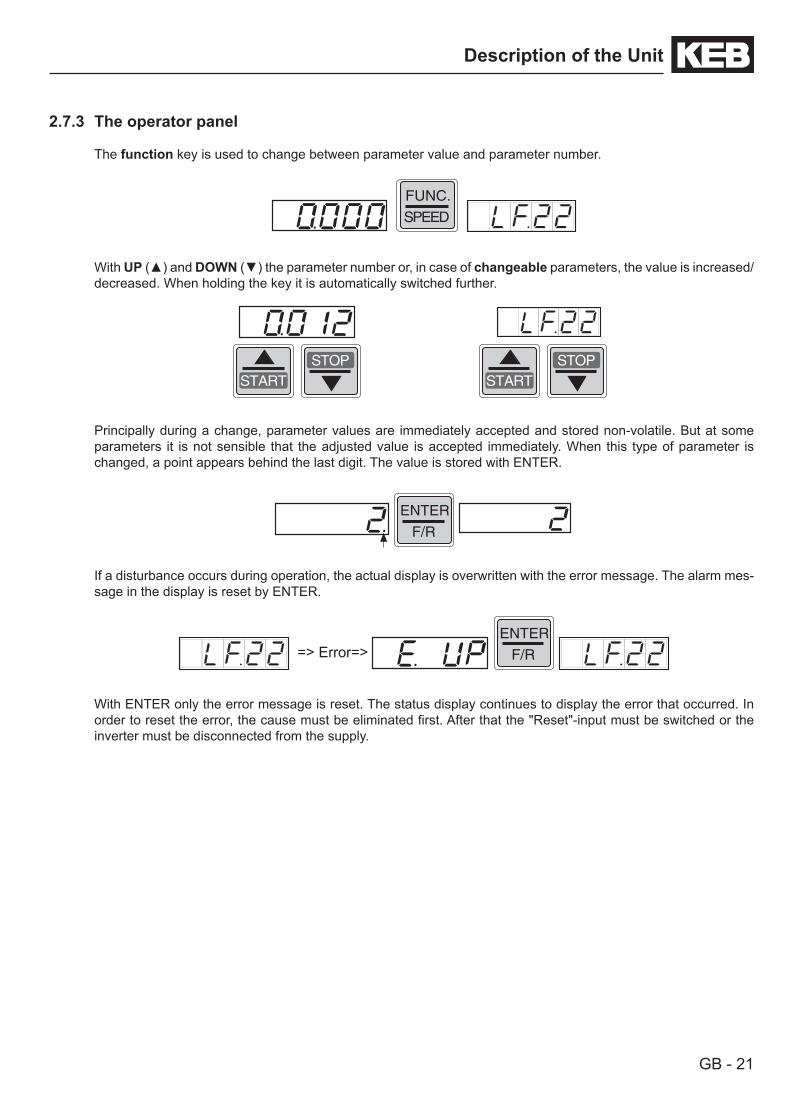
2.7.3 The operator panel
The function key is used to change between parameter value and parameter number.
FUNC.
SPEED
With UP () and DOWN () the parameter number or, in case of changeable parameters, the value is increased/decreased. When holding the key it is automatically switched further.
START
STOP
START
STOP
Principally during a change, parameter values are immediately accepted and stored non-volatile. But at some parameters it is not sensible that the adjusted value is accepted immediately. When this type of parameter is changed, a point appears behind the last digit. The value is stored with ENTER.
ENTER
F/R
If a disturbance occurs during operation, the actual display is overwritten with the error message. The alarm mes-sage in the display is reset by ENTER.
=> Error=>
ENTER
F/R
With ENTER only the error message is reset. The status display continues to display the error that occurred. In order to reset the error, the cause must be eliminated first. After that the "Reset"-input must be switched or the inverter must be disconnected from the supply.

GB - 22
Parameter Description
3. Parameter Description3.1 Overview of parameter groups
The operating menu is devided into following parameter groups :Gruppe Name Function
Lb Lift basic Basic settingLd Lift drive Entry of the motor dataLC Lift encoder Adjustment of motor and shaft encoderLF Lift Function Lift-specific adjustmentsLP Lift Posi Adjustment for positioning operation and ogive runLI Lift Info Information, running messages, measured values, error memoryLA Lift Analog Adjustment of analog in- and outputs
The adjustment of the parameters must absolutely be made in ascending order, because:the operating menu optimizes itself by displaying only the required parameters.• the lower parameters effect pre-settings for the following parameters.• otherwise settings can be overwritten otherwise.•
In case of doubt the factory settings should be kept.
3.2 Basic settings
Display Name Setting range Default settingLb.00 Parameter group BASIC -Lb.01 Password 10…65535 11Lb.02 Customer-specific password 11…65535 11Lb.03 Drive selection 0…4 AGLb.04 Positioning mode 0…4 1Lb.05 Setpoint selection 1…6 1Lb.06 Reset to factory setting 0…1 0Lb.07 Pretorque on/off 0…1 0Lb.08 Switching frequency 2, 4, 8, 12, 16 16Lb.10 In-/output configuration 1…2 1Lb.11 Input function for terminal X2A.15 0…9 1Lb.12 Input function for terminal X2A.17 0…9 5Lb.13 Input function for terminal X2A.13 0…9 0Lb.14 Output function for X2A.24 0…8 1Lb.15 Output function for X2A.27 0…8 2Lb.16 Output function for X2A.18 0…8 3Lb.17 Output function for X2A.19 0…8 4Lb.18 Brake resistance value 0,5…300,0 Ω 30,0 ΩLb.19 Safety gear release 0...1 0
Lb.00 Display of the current parameter group „Basic“
Lb.01 PasswordTo protect the lift drive against unauthorized access, a password is to be entered before parameterizing. If no password has been set with Lb.02, the factory setting „11“ is valid.
Input Function10…65535 Input of password
10 Inhibits the programming11 Factory setting
GB - 23
Parameter Description
Display MeaningUS_ro User read-only, programming inhibited, parameter can be read-onlyUS_on User on, programming enabled
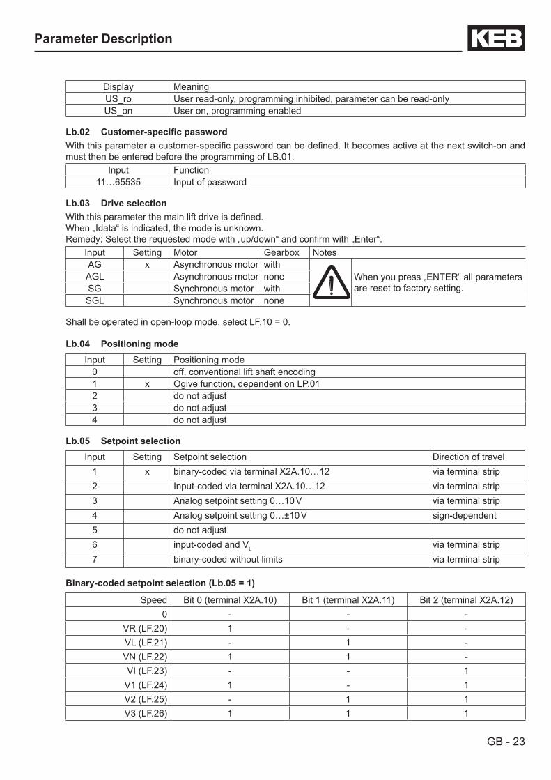
Lb.02 Customer-specificpasswordWith this parameter a customer-specific password can be defined. It becomes active at the next switch-on and must then be entered before the programming of LB.01.
Input Function11…65535 Input of password
Lb.03 Drive selectionWith this parameter the main lift drive is defined.When „Idata“ is indicated, the mode is unknown.Remedy: Select the requested mode with „up/down“ and confirm with „Enter“.
Input Setting Motor Gearbox NotesAG x Asynchronous motor with
When you press „ENTER“ all parameters are reset to factory setting.
AGL Asynchronous motor noneSG Synchronous motor withSGL Synchronous motor none
Shall be operated in open-loop mode, select LF.10 = 0.
Lb.04 Positioning modeInput Setting Positioning mode
0 off, conventional lift shaft encoding1 x Ogive function, dependent on LP.012 do not adjust3 do not adjust4 do not adjust
Lb.05 Setpoint selectionInput Setting Setpoint selection Direction of travel
1 x binary-coded via terminal X2A.10…12 via terminal strip2 Input-coded via terminal X2A.10…12 via terminal strip3 Analog setpoint setting 0…10 V via terminal strip4 Analog setpoint setting 0…±10 V sign-dependent5 do not adjust6 input-coded and VL via terminal strip7 binary-coded without limits via terminal strip
Binary-coded setpoint selection (Lb.05 = 1)
Speed Bit 0 (terminal X2A.10) Bit 1 (terminal X2A.11) Bit 2 (terminal X2A.12)0 - - -
VR (LF.20) 1 - -VL (LF.21) - 1 -VN (LF.22) 1 1 -VI (LF.23) - - 1
V1 (LF.24) 1 - 1V2 (LF.25) - 1 1V3 (LF.26) 1 1 1

GB - 24
Parameter Description
Input-coded setpoint selection (Lb.05 = 2)
Speed Terminal X2A.10 Terminal X2A.11 Terminal X2A.12 Terminal X2A.13 Terminal X2A.170 - - - - -
VL (LF.21) 1 - - - -VN (LF.22) - 1 - - -VI (LF.23) - - 1 - -V1 (LF.24) - - - 1 -VR (LF.20) - - - - 1
Analog setpoint setting (Lb.05 = 3 or 4)The analog setpoint setting is done over terminals X2A.1 and X2A.2. The speed is calculated according to fol-lowing formula:value „3“ 0…10 V correspond to 0…maximum lift speed (LF.01)value „4“ 0…±10 V correspod to 0…±maximum lift speed (LF.01)
Ifthedriveprofileisgeneratedwiththesetpointvalue,thevaluesLF.30…LF.36mustbesetto„off“.
Input-coded setpoint selection AND VL (Lb.05=6)
Speed Terminal X2A.17 T e r m i n a l X2A.10
Terminal X2A.11 Terminal X2A.12 Terminal X2A.13
0 0 0 0 0 0VL (LF.21) 0 1 0 0 0VN (LF.22) 0 x 1 0 0VI (LF.23) 0 x x 1 0V1 (LF.24) 0 x x x 1VR (LF.20) 1 x x x x
Symbols: 1 = Input is set at 24 V 0 = Input may not be set x = Input setting has no effect
Lb.06 Reset to factory settingInput Setting Description
0 x -1 Factory setting is loaded by setting „1“ and pressing 'ENTER'. After that a power-on
reset must be made.
Lb.07 PretorqueInput Setting Pretorque Description
0 x off Is adjusted for drives with gearboxes.1 on Analog signal at the terminals X2A.3 and X2A.4 is used for the
torque precontrol with gearless drives.
Adjustment of amplification and offset see parameters LA.12 / LA.14.
Lb.08 Switching frequencyFactory setting: 16kHz
GB - 25
Parameter Description
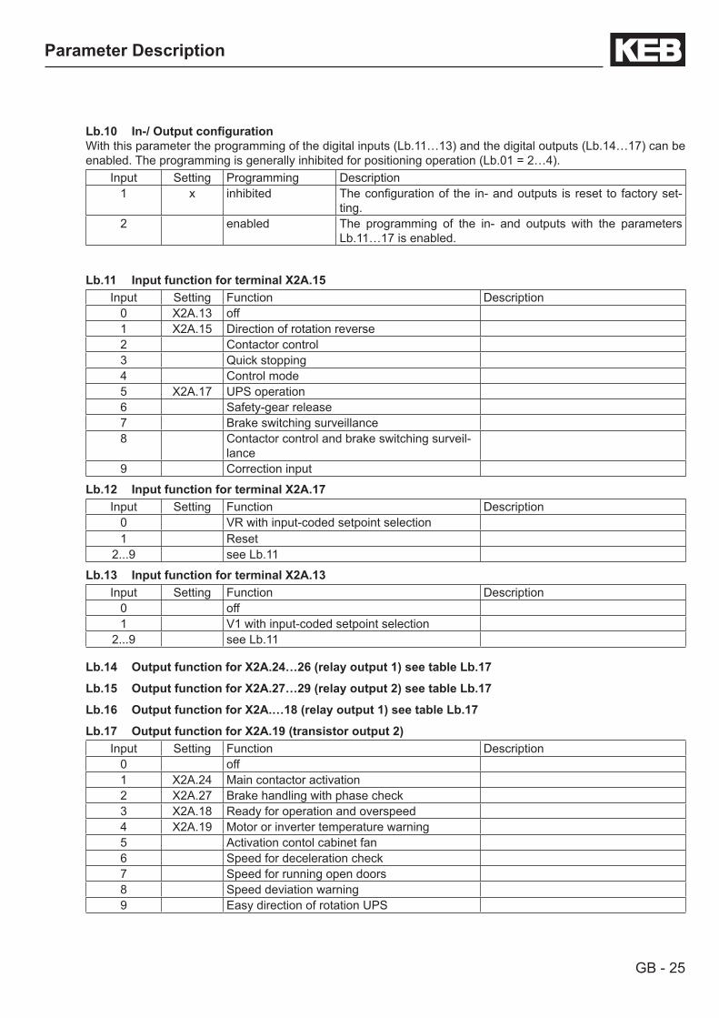
Lb.10 In-/OutputconfigurationWith this parameter the programming of the digital inputs (Lb.11…13) and the digital outputs (Lb.14…17) can be enabled. The programming is generally inhibited for positioning operation (Lb.01 = 2…4).
Input Setting Programming Description1 x inhibited The configuration of the in- and outputs is reset to factory set-
ting.2 enabled The programming of the in- and outputs with the parameters
Lb.11…17 is enabled.
Lb.11 Input function for terminal X2A.15Input Setting Function Description
0 X2A.13 off1 X2A.15 Direction of rotation reverse2 Contactor control3 Quick stopping4 Control mode5 X2A.17 UPS operation6 Safety-gear release7 Brake switching surveillance8 Contactor control and brake switching surveil-
lance9 Correction input
Lb.12 Input function for terminal X2A.17Input Setting Function Description
0 VR with input-coded setpoint selection1 Reset
2...9 see Lb.11
Lb.13 Input function for terminal X2A.13Input Setting Function Description
0 off1 V1 with input-coded setpoint selection
2...9 see Lb.11
Lb.14 Output function for X2A.24…26 (relay output 1) see table Lb.17
Lb.15 Output function for X2A.27…29 (relay output 2) see table Lb.17
Lb.16 Output function for X2A.…18 (relay output 1) see table Lb.17
Lb.17 Output function for X2A.19 (transistor output 2)Input Setting Function Description
0 off1 X2A.24 Main contactor activation2 X2A.27 Brake handling with phase check3 X2A.18 Ready for operation and overspeed4 X2A.19 Motor or inverter temperature warning5 Activation contol cabinet fan6 Speed for deceleration check7 Speed for running open doors8 Speed deviation warning9 Easy direction of rotation UPS

GB - 26
Parameter Description
Lb.18 Brake resistance valueValue range Setting Description0,5…300,0 Ω 30,0 Ω Input of the actually used brake resistance value. With it the inverter calculates the
refed energy and outputs the result in parameter LI.23. It serves as decision support on whether the employment of a feedback unit would be worth it.
Lb.19 Safety-gear releaseValue range Setting Description
0…1 0 The next drive is executed with hard ramps if value 1 is adjusted, in order to pull the car out of the safety gear.

GB - 27
Parameter Description
3.3 Input of the motor data
Display Name Setting range Default setting AGLd.00 Parameter group drIuE -Ld.01 Power rating 0,10…400,00 kW 4,0 kWLd.02 Rated speed 0,000…4000,000 rpm 1450,000 rpm
Ld.03 Rated current 0,0…710,0 A 1,0 ALd.04 Rated frequency 0,0…710,0 Hz 50,0 HzLd.05 cos phi 0,50…1,00 0,5Ld.06 Rated voltage 120…830 V 400 VLd.07 Winding resistance measure 0…1 0Ld.08 Winding resistance 0,000…250,000 Ω 1,864 ΩLd.09 Winding inductivity 0,00…500,00 mH -Ld.10 Rated torque unit-dependent autoLd.11 Maximum inverter torque unit-dependent autoLd.12 Maximum torque limitation 0,01...32000,00 Nm 0,95 • Ld.11Ld.13 Field weakening speed 0…32000 rpm autoLd.14 Motor identification 0…1 -Ld.15 DSM max. inductance 0…500 mH autoLd.20 Maximum torque at UPS operation 0,01...32000,00 Nm autoLd.22 - only for internal use - - -Ld.23 - only for internal use - - -Ld.24 Rotation change UPS 0…1 1
Presettings are specified for ‚Lb.03=0: ASM with gear (AG)‘.If Lb.03 is adjusted unequal 0, presettings can deviate from the specified values above.
Ld.00 Display of current parameter group „drIvE“Drive-specific data are entered in this parameter group. Depending on the adjusted drive type (Lb.03) only certain data are requerid.
Ld.01 Power ratingValue range Setting Description
0,10…400,00 kW 4,0 kW Input of the motor power rating according to motor name plate. Only display at synchronousmotors.
Ld.02 Rated speedValue range Setting Description
0,00…4000,00 rpm 1450 rpm Input of the motor rated speed according to motor name plate.
Ld.03 Rated currentValue range Setting Description0,0…710,0 A - Input of the motor rated current according to motor name plate.
Ld.04 Motor rated frequencyValue range Setting Description
0,0…710,0 Hz 50,0 Hz Input of the motor rated frequency according to motor name plate.For synchronous motors frequency and speed depend on each other accor-ding to following formula.
Motor speed =Frequency • 60
——————————Pole-pair number
The pole-pair number is always a whole-numbered value !
GB - 28
Parameter Description
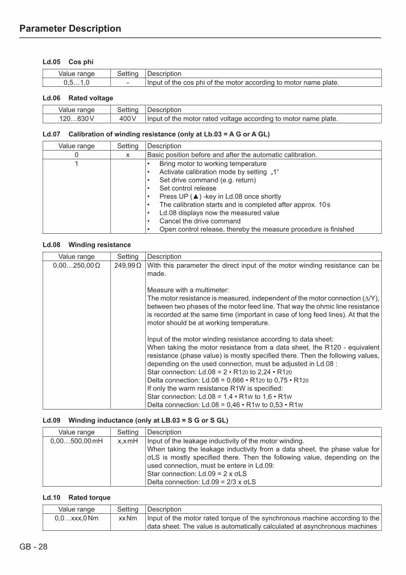
Ld.05 Cos phiValue range Setting Description
0,5…1,0 - Input of the cos phi of the motor according to motor name plate.
Ld.06 Rated voltageValue range Setting Description120…830 V 400 V Input of the motor rated voltage according to motor name plate.
Ld.07 Calibration of winding resistance (only at Lb.03 = A G or A GL)Value range Setting Description
0 x Basic position before and after the automatic calibration.1 Bring motor to working temperature•
Activate calibration mode by setting „1“• Set drive command (e.g. return) • Set control release• Press UP () -key in Ld.08 once shortly• The calibration starts and is completed after approx. 10 s• Ld.08 displays now the measured value• Cancel the drive command• Open control release, thereby the measure procedure is finished•
Ld.08 Winding resistanceValue range Setting Description
0,00…250,00 Ω 249,99 Ω With this parameter the direct input of the motor winding resistance can be made.
Measure with a multimeter:The motor resistance is measured, independent of the motor connection (∆/Y), between two phases of the motor feed line. That way the ohmic line resistance is recorded at the same time (important in case of long feed lines). At that the motor should be at working temperature.
Input of the motor winding resistance according to data sheet:When taking the motor resistance from a data sheet, the R120 - equivalent resistance (phase value) is mostly specified there. Then the following values, depending on the used connection, must be adjusted in Ld.08 :Star connection: Ld.08 = 2 • R120 to 2,24 • R120Delta connection: Ld.08 = 0,666 • R120 to 0,75 • R120If only the warm resistance R1W is specified:Star connection: Ld.08 = 1,4 • R1W to 1,6 • R1WDelta connection: Ld.08 = 0,46 • R1W to 0,53 • R1W
Ld.09 Winding inductance (only at LB.03 = S G or S GL)Value range Setting Description
0,00…500,00 mH x,x mH Input of the leakage inductivity of the motor winding.When taking the leakage inductivity from a data sheet, the phase value for σLS is mostly specified there. Then the following value, depending on the used connection, must be entere in Ld.09:Star connection: Ld.09 = 2 x σLSDelta connection: Ld.09 = 2/3 x σLS
Ld.10 Rated torqueValue range Setting Description
0,0…xxx,0 Nm xx Nm Input of the motor rated torque of the synchronous machine according to the data sheet. The value is automatically calculated at asynchronous machines
GB - 29
Parameter Description
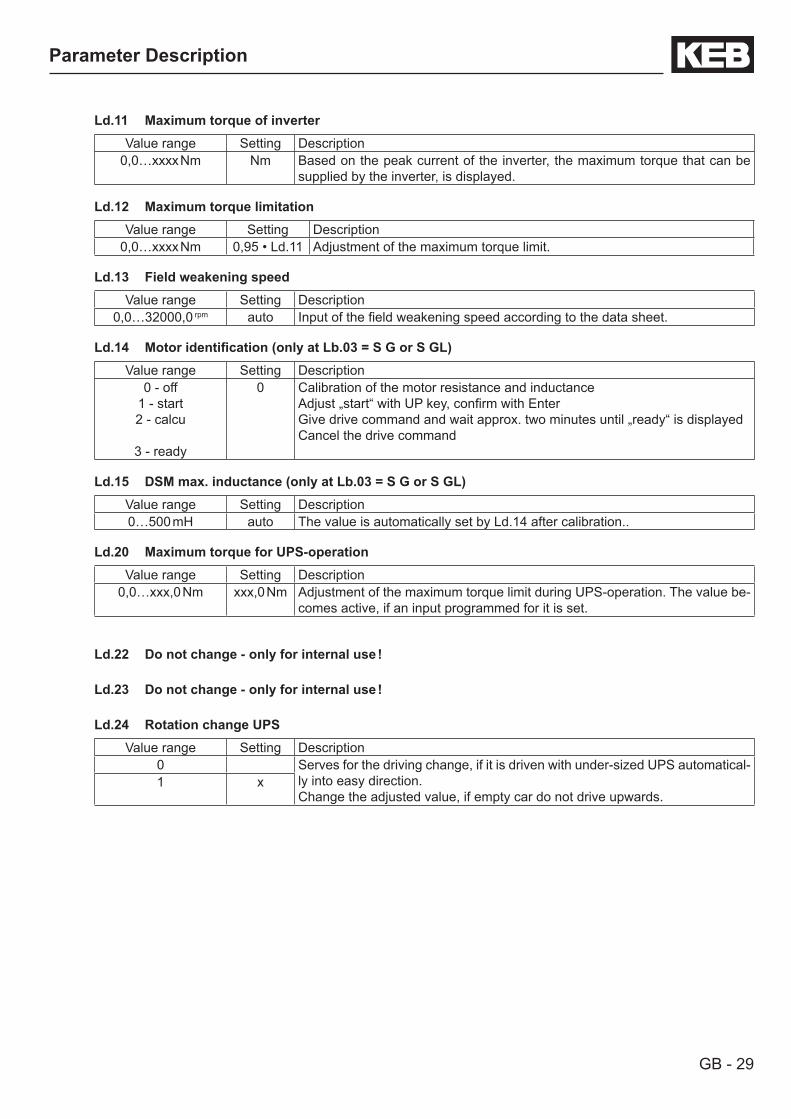
Ld.11 Maximum torque of inverterValue range Setting Description
0,0…xxxx Nm Nm Based on the peak current of the inverter, the maximum torque that can be supplied by the inverter, is displayed.
Ld.12 Maximum torque limitationValue range Setting Description
0,0…xxxx Nm 0,95 • Ld.11 Adjustment of the maximum torque limit.
Ld.13 Field weakening speedValue range Setting Description
0,0…32000,0 rpm auto Input of the field weakening speed according to the data sheet.
Ld.14 Motoridentification(onlyatLb.03=SGorSGL)Value range Setting Description
0 - off1 - start2 - calcu
3 - ready
0 Calibration of the motor resistance and inductanceAdjust „start“ with UP key, confirm with EnterGive drive command and wait approx. two minutes until „ready“ is displayedCancel the drive command
Ld.15 DSM max. inductance (only at Lb.03 = S G or S GL)Value range Setting Description0…500 mH auto The value is automatically set by Ld.14 after calibration..
Ld.20 Maximum torque for UPS-operationValue range Setting Description
0,0…xxx,0 Nm xxx,0 Nm Adjustment of the maximum torque limit during UPS-operation. The value be-comes active, if an input programmed for it is set.
Ld.22 Do not change - only for internal use !
Ld.23 Do not change - only for internal use !
Ld.24 Rotation change UPSValue range Setting Description
0 Serves for the driving change, if it is driven with under-sized UPS automatical-ly into easy direction.Change the adjusted value, if empty car do not drive upwards.
1 x

GB - 30
Parameter Description
3.4 Adjustment of the speed encoderDisplay Name Setting range Default settingLC.00 Parameter group Enc -LC.01 Selection motor encoder input 0…1 0LC.02 Encoder 1 Status - -LC.03 Encoder alarm mode 0...15 0LC.11 Display Interface 1 - -LC.12 Increments Encoder 1 0…65535 inc 2500 InkLC.13 Track change and travel direction inverting Encoder 1 0…19 0LC.14 Encoder pole-pair 1…10 1LC.15 Teach-in system position 0…3 0LC.16 System position value 0…65535 -LC.17 Filter time for actual speed Encoder 1 0…5 1LC.18 System position detection (SPI) 0…15 0LC.19 System position mode 0…1 autoLC.21 Display Interface 2 - -LC.22 Increments Encoder 2 0…65535 inc 2500 incLC.23 Track change and travel direction inverting Encoder 2 0…19 0LC.24 Operation mode output 0...127 0LC.27 Filter time for actual speed Encoder 2 0…5 3LC.30 Encoder 1 type - -LC.31 Encoder 1 read/write data 0…4 4LC.32 Encoder 1 SSI data code 0…1 0LC.33 Encoder 1 SSI singleturn resolution 0…13 Bit 10 BitLC.40 SSI Multiturn-resolution 0…13 Bit 12 BitLC.41 SSI clock frequency 0…1 0LC.42 SSI data format 0…1 1LC.43 SSI voltage surveillance 0…1 0
LC.00 Parameter group The LC parameters (Lift Encoder) include all parameters for the adjustment of the encoder and the encoder in-terfaces.
LC.01 Selection motor encoder inputInput Setting Description
0 x Motor speed encoder is connected to input X3A.1 Motor speed encoder is connected to input X3B .
LC.02 Encoder 1 StatusThis parameter shows the status of intelligent encoders (Hiperface, ENDAT, SIN/COS) and the encoder interface 1. Depending on the encoder only certain messages are possible. An error is triggered only upon control reset, even though it is already displayed in LC.02.
Inverter status Value Descriptionno error 16 System position values aer transferred, encoder and interface are all right.
continued on next page

GB - 31
Parameter Description
Inverter status Value Description
Error „E.EncC“
Please con-sider LC.31 and/or chapter 2.3.
The correct evaluation of the system position is no longer ensured. The error E.EncC can only be reset via parameters Ec.00/LC.11. Exception ! An error, due to wrong encoder increments (value 70), is immediately reset, once the correct encoder increments are adjusted. Attention, if the control release is still set, the modulation is enabled !
64 Encoder unknown and not supported.68 No encoder connected of encoder breakage detection has tripped.69 System deviation too large. The position, determined from the incremental signals,
and the absolute position (from absolute track, zero signal or serial read) no longer match or cannot be corrected. see LC.12/ LC.22!
70 Adjusted increments do not match the encoder increments.71 Interface type is unknown: Interface was not identified.75 Encoder temperature is too high (message from encoder)76 Speed is too high (message from encoder)77 Encoder signals are outside the specifications (message from encoder)78 Encoder has an internal defect (message from encocer)92 Encoder is formatted. When writing on an encoder, whose storage structure does
not correspond to the KEB definition, the storage areas are reorganized, so that they can be written on. Depending on the storage structure, this process can take several seconds.
96 New value recognized, because another encoder was plugged in.98 Interface is busy.
Error „E.Enc1“
During read out of the encoder the error „E.Enc1“ is output.97 KEB identifier undefined. Storage structure of the encoder does not correspond to
the KEB definition, thus data cannot be read. By writing on it the encoder is defined. The error can be reset as follows:• Writing a system position into Ec.2.• Carry out a system position alignment .
Error „E.Hyb“ 0255 No communication between interface and control board
LC.03 Encoder alarm modeInput Setting Description
0 x off2 Channel 18 Channel 210 Channel 1 and 2
LC.11 Display Interface 1Shows which encoder interface is installed and thus which encoder may be connected to channel 1 (X3A).
Value Installed encoder interface0 none11 Hiperface12 Incremental encoder input 24 V HTL13 Incremental encoder input TTL with error detection14 SIN/COS15 Incremental encoder input 24 V HTL with error detection (push-pull)16 ENDAT17 Incremental encoder input 24 V HTL with error detection19 Resolver
continued on next page
GB - 32
Parameter Description
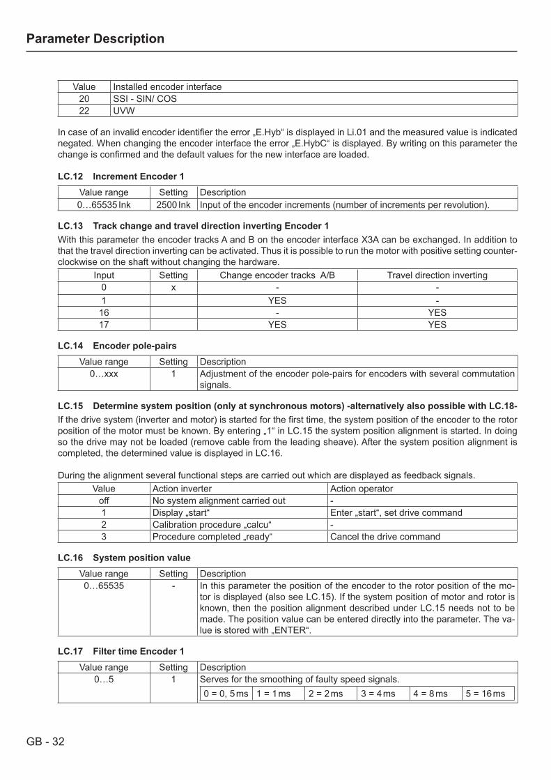
Value Installed encoder interface20 SSI - SIN/ COS22 UVW
In case of an invalid encoder identifier the error „E.Hyb“ is displayed in Li.01 and the measured value is indicated negated. When changing the encoder interface the error „E.HybC“ is displayed. By writing on this parameter the change is confirmed and the default values for the new interface are loaded.
LC.12 Increment Encoder 1Value range Setting Description0…65535 Ink 2500 Ink Input of the encoder increments (number of increments per revolution).
LC.13 Track change and travel direction inverting Encoder 1With this parameter the encoder tracks A and B on the encoder interface X3A can be exchanged. In addition to that the travel direction inverting can be activated. Thus it is possible to run the motor with positive setting counter-clockwise on the shaft without changing the hardware.
Input Setting Change encoder tracks A/B Travel direction inverting0 x - -1 YES -
16 - YES17 YES YES
LC.14 Encoder pole-pairsValue range Setting Description
0…xxx 1 Adjustment of the encoder pole-pairs for encoders with several commutation signals.
LC.15 Determine system position (only at synchronous motors) -alternatively also possible with LC.18-If the drive system (inverter and motor) is started for the first time, the system position of the encoder to the rotor position of the motor must be known. By entering „1“ in LC.15 the system position alignment is started. In doing so the drive may not be loaded (remove cable from the leading sheave). After the system position alignment is completed, the determined value is displayed in LC.16.
During the alignment several functional steps are carried out which are displayed as feedback signals.Value Action inverter Action operator
off No system alignment carried out -1 Display „start“ Enter „start“, set drive command2 Calibration procedure „calcu“ -3 Procedure completed „ready“ Cancel the drive command
LC.16 System position valueValue range Setting Description0…65535 - In this parameter the position of the encoder to the rotor position of the mo-
tor is displayed (also see LC.15). If the system position of motor and rotor is known, then the position alignment described under LC.15 needs not to be made. The position value can be entered directly into the parameter. The va-lue is stored with „ENTER“.
LC.17 Filter time Encoder 1Value range Setting Description
0…5 1 Serves for the smoothing of faulty speed signals.0 = 0, 5 ms 1 = 1 ms 2 = 2 ms 3 = 4 ms 4 = 8 ms 5 = 16 ms

GB - 33
Parameter Description
LC.18 System position detection (SPI)Value range Setting Description
0 x offThe function SPI (static pole identification) finds the system position without rotation of the motor. LC.18 determines when the function be-comes active. The sum of the values must be entered in case of several possibilities.
1 after control release2 after switching on4 after direction of rotation re-
lease8 after Reset
If the values of LC.16 should deviate more than 2500 increments in spite of several procedures of calibration, calibration by LC.15 is required.
LC.19 System position modeValue range Setting Description
0 0, auto Ld is unequal Lq This parameter is determined by the automatic motor identification Ld.14.1 Ld is equal Lq
LC.21 Display Interface 2Indicates which encoder interface is installed and thus which encoder may be connected to channel 2 (X3B).
Value Installed encoder interface0 none1 Incremental encoder input TTL2 Incremental encoder output 5 V3 Incremental encoder input and output direct 4 Incremental encoder input and output TTL6 Sychron-serial interface (SSI)9 Incremental encoder output TTL of resolver via channel 2
10 Incremental encoder output TTL
In case of an invalid encoder identifier the error „E.Hyb“ is displayed in Li.01 and the measured value is indicated negated. When changing the encoder interface the error „E.HybC“ is displayed. By writing on this parameter the change is confirmed and the default values for the new interface are loaded.
LC.22 Increments Encoder 2Value range Setting Description0…65535 Ink 4096 Inc Input of the encoder increments (number of increments per revolution).
LC.23 Track change and travel direction inverting Encoder 2With this parameter the encoder tracks A and B on the encoder interface X3B can be exchanged. In addition to that the travel direction inverting can be activated. Thus it is possible to run the motor with positive setting counter-clockwise on the shaft without changing the hardware.
Input Setting Change encoder tracks A/B Travel direction inverting0 x - -1 YES -
16 - YES17 YES YES

GB - 34
Parameter Description
LC.24 Operation mode outputIf one of the encoder channels is used as encoder output, the output increments per revolution can be adapted to the requirements of the control card.
Input Setting Description0 x off1 256 Incr.5 1024 Incr.9 2048 Incr.13 4096 Incr.
LC.27 Filter time Encoder 2Value range Setting Description
0…5 3 Serves for the smoothing of faulty speed signals.0 = 0,5 ms 1 = 1 ms 2 = 2 ms 3 = 4 ms 4 = 8 ms 5 = 16 ms
LC.30 Encoder 1 TypeDisplay Description
0 no encoder identified2 SCS 60/707 SCM 60/7034 SRS 50/6039 SRM 50/6064 undefined type
LC.31 Encoder 1 read/write dataInput Setting Description0…14 0 In case of „E.EncC“ together with EnDat- or Hiperface encoders: set
Lb.01 = 2206 + ENTEREC.38 = 2 + ENTERUd.01 = 11 + ENTER
LC.32 Encoder 1 SSI data code
Input Setting Description0 x Binary-coded1 Graycode
LC.33 Encoder 1 SSI singleturn resolutionInput Setting Description
0…13 Bit 10 Bit This parameter adjusts the number of bits of the SSI data word to the con-nected encoder. The resolution of the digital singleturn absolute position is determined by the number of bits.
LC.40 SSI Multiturn-resolutionInput Setting Description
0…13 Bit 12 Bit Number of Bits for the multiturn-resolution, if a SSI multiturn-absolute valure encoder is connected.

GB - 35
Parameter Description
LC.41 SSI Clock frequencyAdjustment of the clock frequency for SSI-encoder.
Input Setting Description0 x 156,25 kHz1 312,5 kHz
LC.42 SSI Data formatInput Setting Description
0 x Binary-coded1 Graycode
LC.43 SSI Voltage monitoringInput Setting Description
0 x off1 on
GB - 36
Parameter Description
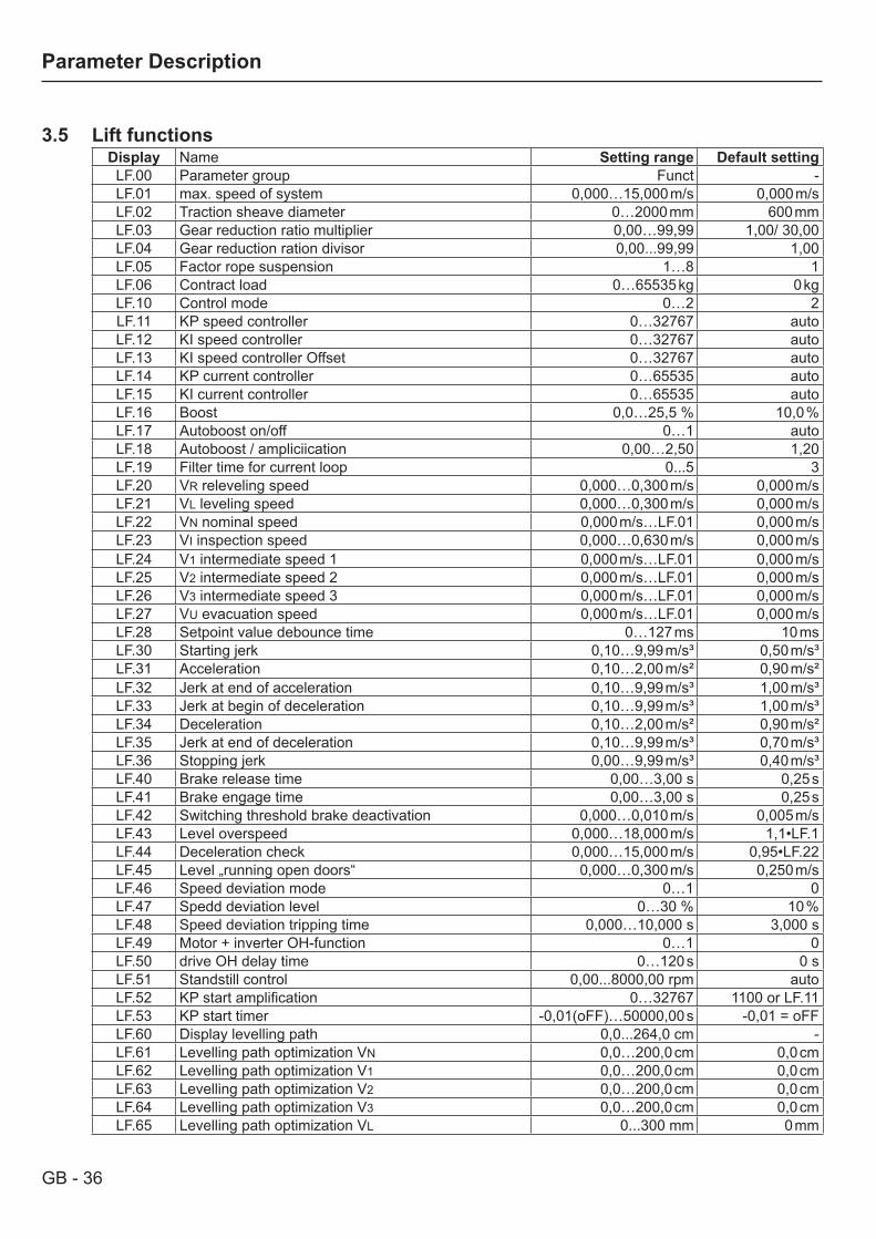
3.5 Lift functionsDisplay Name Setting range Default settingLF.00 Parameter group Funct -LF.01 max. speed of system 0,000…15,000 m/s 0,000 m/sLF.02 Traction sheave diameter 0…2000 mm 600 mmLF.03 Gear reduction ratio multiplier 0,00…99,99 1,00/ 30,00LF.04 Gear reduction ration divisor 0,00...99,99 1,00LF.05 Factor rope suspension 1…8 1LF.06 Contract load 0…65535 kg 0 kgLF.10 Control mode 0…2 2LF.11 KP speed controller 0…32767 autoLF.12 KI speed controller 0…32767 autoLF.13 KI speed controller Offset 0…32767 autoLF.14 KP current controller 0…65535 autoLF.15 KI current controller 0…65535 autoLF.16 Boost 0,0…25,5 % 10,0 %LF.17 Autoboost on/off 0…1 autoLF.18 Autoboost / ampliciication 0,00…2,50 1,20LF.19 Filter time for current loop 0...5 3LF.20 VR releveling speed 0,000…0,300 m/s 0,000 m/sLF.21 VL leveling speed 0,000…0,300 m/s 0,000 m/sLF.22 VN nominal speed 0,000 m/s…LF.01 0,000 m/sLF.23 VI inspection speed 0,000…0,630 m/s 0,000 m/sLF.24 V1 intermediate speed 1 0,000 m/s…LF.01 0,000 m/sLF.25 V2 intermediate speed 2 0,000 m/s…LF.01 0,000 m/sLF.26 V3 intermediate speed 3 0,000 m/s…LF.01 0,000 m/sLF.27 VU evacuation speed 0,000 m/s…LF.01 0,000 m/sLF.28 Setpoint value debounce time 0…127 ms 10 msLF.30 Starting jerk 0,10…9,99 m/s³ 0,50 m/s³LF.31 Acceleration 0,10…2,00 m/s² 0,90 m/s²LF.32 Jerk at end of acceleration 0,10…9,99 m/s³ 1,00 m/s³LF.33 Jerk at begin of deceleration 0,10…9,99 m/s³ 1,00 m/s³LF.34 Deceleration 0,10…2,00 m/s² 0,90 m/s²LF.35 Jerk at end of deceleration 0,10…9,99 m/s³ 0,70 m/s³LF.36 Stopping jerk 0,00…9,99 m/s³ 0,40 m/s³LF.40 Brake release time 0,00…3,00 s 0,25 sLF.41 Brake engage time 0,00…3,00 s 0,25 sLF.42 Switching threshold brake deactivation 0,000…0,010 m/s 0,005 m/sLF.43 Level overspeed 0,000…18,000 m/s 1,1•LF.1LF.44 Deceleration check 0,000…15,000 m/s 0,95•LF.22LF.45 Level „running open doors“ 0,000…0,300 m/s 0,250 m/sLF.46 Speed deviation mode 0…1 0LF.47 Spedd deviation level 0…30 % 10 %LF.48 Speed deviation tripping time 0,000…10,000 s 3,000 sLF.49 Motor + inverter OH-function 0…1 0LF.50 drive OH delay time 0…120 s 0 sLF.51 Standstill control 0,00...8000,00 rpm autoLF.52 KP start amplification 0…32767 1100 or LF.11LF.53 KP start timer -0,01(oFF)…50000,00 s -0,01 = oFFLF.60 Display levelling path 0,0...264,0 cm -LF.61 Levelling path optimization VN 0,0…200,0 cm 0,0 cmLF.62 Levelling path optimization V1 0,0…200,0 cm 0,0 cmLF.63 Levelling path optimization V2 0,0…200,0 cm 0,0 cmLF.64 Levelling path optimization V3 0,0…200,0 cm 0,0 cmLF.65 Levelling path optimization VL 0...300 mm 0 mm

GB - 37
Parameter Description
LF.00 Display of current parameter group „Funct“
LF.01 Max. speed of system
This parameter limits the speed of the system to the adjusted value. For analog setpoint setting applies 0…±10 V correspond to 0…±LF.01.
Value range Setting Description0,000…15,000 m/s 0,000 m/s
LF.02 Traction sheave diameter
Value range Setting Description0…2000 mm 600 mm Enter the diameter of the employed leading sheave.
LF.03 Gear reduction ratio/multiplier
Value range Setting Description0,00…99,99 1,00/
30,00Adjustment according to gearbox name plate (possible determination by counting the revolutions of the handwheel at one revolution of the leading sheave). Example: i = 43:3LF.3=43For gearless motors adjust value „1“.
LF.04 Gear reduction ratio/divisor
Value range Setting Description0,00…99,99 1,00 Adjustment according to gearbox name plate (possible determination by
counting the revolutions of the handwheel at one revolution of the leading sheave).Example: i = 43:3LF.4=3 For gearless motors adjust value „1“.
LF.05 Factor rope suspension
Value range Setting Description1…8 1 Adjustment according to system data (1:1…8:1)
LF.06 Contract load
Value range Setting Description0…65535 kg 0 Adjustment according to system data (possibly number of persons x 75 kg)
LF.10 Control mode
Value range Setting Description0 Without speed encoder (open-loop)1 Control procedure switchable by digital input2 x With speed encoder (closed-loop)
LF.11 KP Speed controller
Value range Setting Description0…32767 auto Adjustment of the P-amplification of the speed controller. If the KP-values are
too large vibrations occur during the constant drive. If the KP-values are too small a deviation between setpoint and actual value occurs. It results in tran-sient effects after the acceleration.
GB - 38
Parameter Description
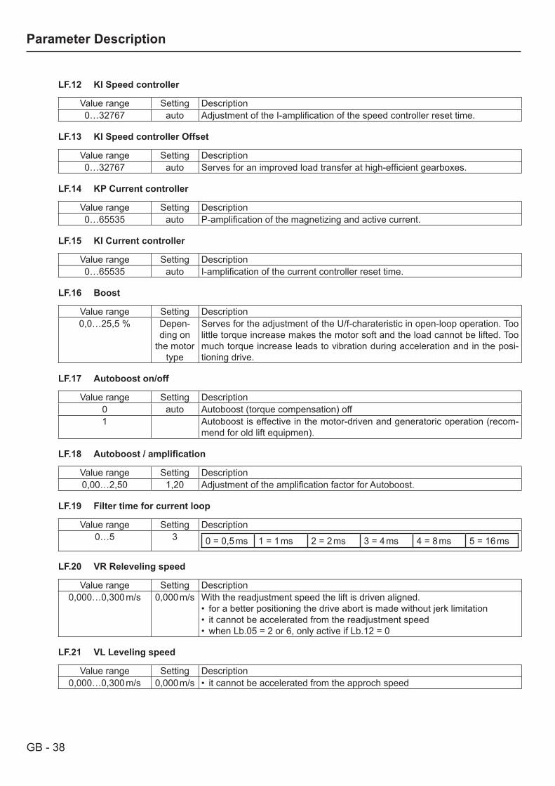
LF.12 KI Speed controller
Value range Setting Description0…32767 auto Adjustment of the I-amplification of the speed controller reset time.
LF.13 KI Speed controller Offset
Value range Setting Description0…32767 auto Serves for an improved load transfer at high-efficient gearboxes.
LF.14 KP Current controller
Value range Setting Description0…65535 auto P-amplification of the magnetizing and active current.
LF.15 KI Current controller
Value range Setting Description0…65535 auto I-amplification of the current controller reset time.
LF.16 Boost
Value range Setting Description0,0…25,5 % Depen-
ding on the motor
type
Serves for the adjustment of the U/f-charateristic in open-loop operation. Too little torque increase makes the motor soft and the load cannot be lifted. Too much torque increase leads to vibration during acceleration and in the posi-tioning drive.
LF.17 Autoboost on/off
Value range Setting Description0 auto Autoboost (torque compensation) off1 Autoboost is effective in the motor-driven and generatoric operation (recom-
mend for old lift equipmen).
LF.18 Autoboost/amplification
Value range Setting Description0,00…2,50 1,20 Adjustment of the amplification factor for Autoboost.
LF.19 Filter time for current loop
Value range Setting Description0…5 3 0 = 0,5 ms 1 = 1 ms 2 = 2 ms 3 = 4 ms 4 = 8 ms 5 = 16 ms
LF.20 VR Releveling speed
Value range Setting Description0,000…0,300 m/s 0,000 m/s With the readjustment speed the lift is driven aligned.
• for a better positioning the drive abort is made without jerk limitation• it cannot be accelerated from the readjustment speed• when Lb.05 = 2 or 6, only active if Lb.12 = 0
LF.21 VL Leveling speed
Value range Setting Description0,000…0,300 m/s 0,000 m/s • it cannot be accelerated from the approch speed

GB - 39
Parameter Description
LF.22 VN Nominal speed
Value range Setting Description0,000 m/s…LF.01 0,000
LF.23 VI Inspection speed
Value range Setting Description0,000…0,630 m/s 0,000 m/s • it cannot be accelerated from the inspection speed
LF.24 V 1 intermediate speed 1
Value range Setting Description0,000 m/s…LF.01 0,000 m/s • when Lb.05 = 2 or 6, only active if Lb.13 = 1
LF.25 V2 intermediate speed 2
Value range Setting Description0,000 m/s…LF.01 0,000 m/s • not active at Lb.05 = 2 or 6
LF.26 V3 intermediate speed 3
Value range Setting Description0,000 m/s…LF.01 0,000 m/s • not active at Lb.05 = 2 or 6
LF.27 VU Evacuation speed
Value range Setting Description0,000 m/s…LF.01 0,000 m/s • off, if no input is assigned with the function „UPS-operation“
LF.28 Setpoint value debounce time
Value range Setting Description0…127 ms 0 ms
LF.30 Starting jerk
Important for the well-being of passengers in a lift is the so-called jerk or shock, that always occurs during acce-leration processes. This phenomenon even causes objects on conveyor system to topple or fall and puts a heavy strain on mechanical components. People perceive the jerk differently, depending on age, physical and mental constitution and whether the movement was anticipated or not.
Value range Setting Description0,10…9,99 m/s³ 0,50 m/s³ Experience values: 0,5...0,8 m/s³ for nursing homes, hospitals, apart-
ment houses 0,8...1,2 m/s³ for office buildings, banks etc.
LF.31 Acceleration
Value range Setting Description0,10…2,00 m/s² 0,90 m/s² Experience values: 0,5...0,8 m/s² for nursing homes, hospitals, apart-
ment houses 0,8...1,2 m/s² for office buildings, banks etc.
LF.32 Jerk at end of acceleration
Value range Setting Description0,10…9,99 m/s³ 1,00 m/s³ If the jerk at the end of acceleration is adjusted too low, the parameter „dece-
leration“ LF.34 is overridden.
GB - 40
Parameter Description
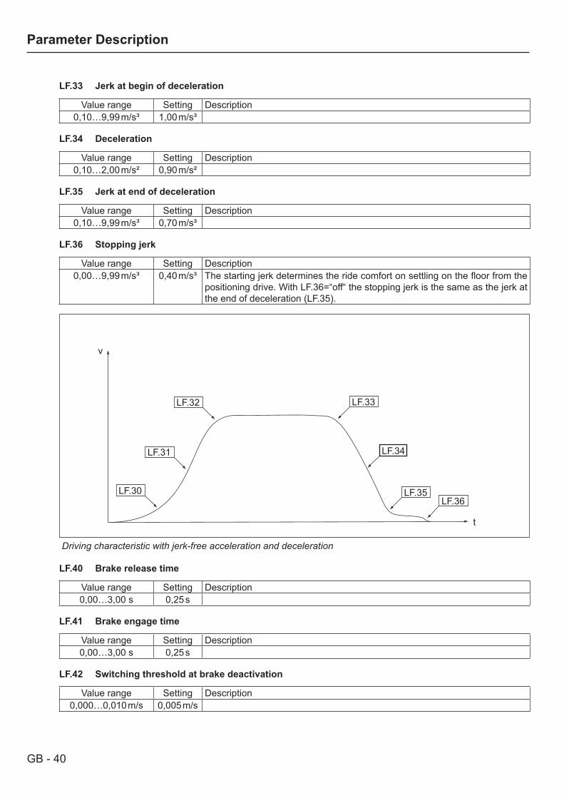
LF.33 Jerk at begin of deceleration
Value range Setting Description0,10…9,99 m/s³ 1,00 m/s³
LF.34 Deceleration
Value range Setting Description0,10…2,00 m/s² 0,90 m/s²
LF.35 Jerk at end of deceleration
Value range Setting Description0,10…9,99 m/s³ 0,70 m/s³
LF.36 Stopping jerk
Value range Setting Description0,00…9,99 m/s³ 0,40 m/s³ The starting jerk determines the ride comfort on settling on the floor from the
positioning drive. With LF.36=“off“ the stopping jerk is the same as the jerk at the end of deceleration (LF.35).
LF.30
LF.31
LF.32 LF.33
LF.34
LF.35LF.36
v
t
Driving characteristic with jerk-free acceleration and deceleration
LF.40 Brake release time
Value range Setting Description0,00…3,00 s 0,25 s
LF.41 Brake engage time
Value range Setting Description0,00…3,00 s 0,25 s
LF.42 Switching threshold at brake deactivation
Value range Setting Description0,000…0,010 m/s 0,005 m/s

GB - 41
Parameter Description
LF.43 Level overspeed
Value range Setting Description0,000…18,000 m/s auto The displayed value is 110 % of the maximum speed (LF.01).
LF.44 Deceleration check level
Value range Setting Description0,000…15,000 m/s auto The displayed value is 96 % of the rated speed LF.22).
LF.45 Level „running open doors“
Value range Setting Description0,000…0,300 m/s 0,250 m/s Defines the maximum approach speed, on falling below this speed the doors
can open.
LF.46 Speed deviation mode
This parameter serves as control, whether the motor speed can follow the actual speed. Die monitoring is active only in closed-loop operation with motor encoder. The tripping level is adjusted with LF.47 . If the function is assi-gned to a digital output, a warning is given.
Value range Setting Descriptionoff x No error switch off. The output condition. The output condition „speed devia-
taion warning“ is set.on Inverter switches off the modulation with error E.hSd (high speed difference).
The output condition „speed deviataion warning“ is set.
LF.47 Speed deviation level
Value range Setting Description0…30 % 10 % The value in percent refers to the selected speed. The detection takes place
at constant run.
LF.48 Speed deviation tripping time
Value range Setting Description0,000…10,000 s 3,000 s Adjustment of the time between detection of a speed deviation and tripping of
the error E.hSd (LF.46 = 1).
LF.49 Motor + Inverter OH-function
This parameter activates the temperature monitoring of motor and inverter. Precondition for the motor monitoring is the connection of a motor temperature sensor to the terminals T1/T2. When the heat sink of the inverter reaches a temperature of 90°C, the error E.OH is triggered and the drive is stopped. If the function is assigned to a digital output, a warning is given. At a temperature of 75°C the output is reset and the drive continues to run. The display shows the warning message „OH“.
Value range Setting Descriptionoff x No error switch-off at overtemperature. The output condition „motor or inverter
excess temperature“ is set.on When the heat sink of the inverter reaches a temperature of 90°C, the error
E.OH is triggered and the drive is stopped. At a temperature of 75°C the error is reset and the drive continues to run. The display shows the warning mes-sage „OH“.At an excess temperature of the motor the drive behaves according to LF.50. The output condition „motor or inverter excess temperature“ is set immedia-tely.
GB - 42
Parameter Description
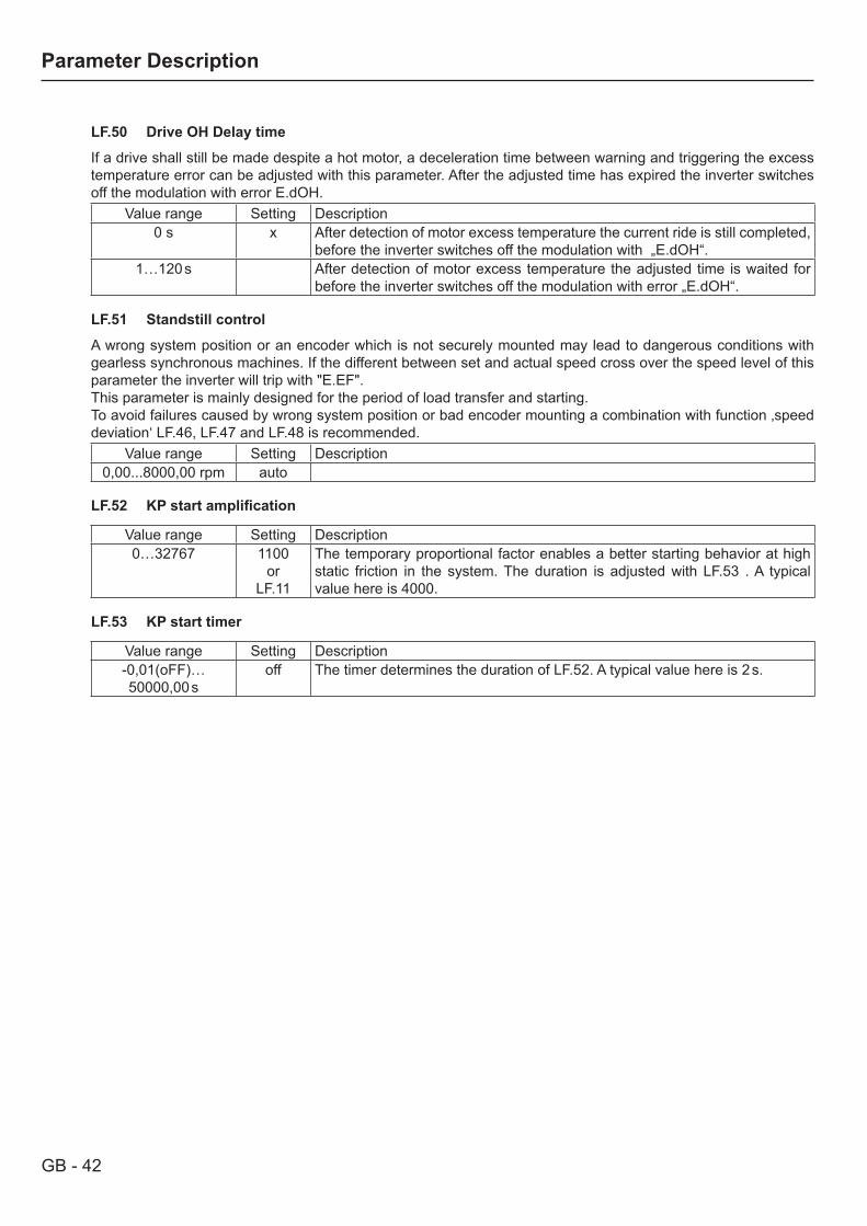
LF.50 Drive OH Delay time
If a drive shall still be made despite a hot motor, a deceleration time between warning and triggering the excess temperature error can be adjusted with this parameter. After the adjusted time has expired the inverter switches off the modulation with error E.dOH.
Value range Setting Description0 s x After detection of motor excess temperature the current ride is still completed,
before the inverter switches off the modulation with „E.dOH“.1…120 s After detection of motor excess temperature the adjusted time is waited for
before the inverter switches off the modulation with error „E.dOH“.
LF.51 Standstill control
A wrong system position or an encoder which is not securely mounted may lead to dangerous conditions with gearless synchronous machines. If the different between set and actual speed cross over the speed level of this parameter the inverter will trip with "E.EF". This parameter is mainly designed for the period of load transfer and starting.To avoid failures caused by wrong system position or bad encoder mounting a combination with function ‚speed deviation‘ LF.46, LF.47 and LF.48 is recommended.
Value range Setting Description0,00...8000,00 rpm auto
LF.52 KPstartamplification
Value range Setting Description0…32767 1100
orLF.11
The temporary proportional factor enables a better starting behavior at high static friction in the system. The duration is adjusted with LF.53 . A typical value here is 4000.
LF.53 KP start timer
Value range Setting Description-0,01(oFF)…50000,00 s
off The timer determines the duration of LF.52. A typical value here is 2 s.
GB - 43
Parameter Description
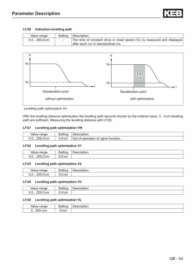
LF.60 Indication levelling path
Value range Setting Description0,0…264,0 cm - The time of constant drive in crawl speed (VL) is measured and displayed
after each run in standardized cm. .
V
t
VN
VE
Deceleration point
V
t
VN
VE
Deceleration point
LF.61
without optimization with optimization
Levelling path optimization VN
With the levelling distance optimization the levelling path become shorter by the entered value. 3…5 cm levelling path are sufficient. Measuring the levelling distance with LF.60.
LF.61 Levelling path optimization VN
Value range Setting Description0,0…200,0 cm 0,0 cm Out of operation at ogive function.
LF.62 Levelling path optimization V1
Value range Setting Description0,0…200,0 cm 0,0 cm
LF.63 Levelling path optimization V2
Value range Setting Description0,0…200,0 cm 0,0 cm
LF.64 Levelling path optimization V3
Value range Setting Description0,0…200,0 cm 0,0 cm
LF.65 Levelling path optimization VL
Value range Setting Description0...300 mm 0 mm

GB - 44
Parameter Description
3.6 Positioning mode / ogive run
Display Name Setting range Default settingLP.00 Display „POSI“ -LP.01 Ogive function 0…2 0LP.02 Minimum deceleration distance (calculated) 0,0…6553,5 cm autoLP.03 Deceleration distance (measured) -3276,7…3276,7 cm 0,0 cmLP.04 Correction distance 0,0…6553,5 cm 10,0 cm
LP.00 Display of current parameter group „POSI“
LP.01 Ogive function
Input Setting Function Descriptionoff x off With switched off ogive function the acceleration at the decelera-
tion point is aborted immediately.With this parameter the ogive function is activated or a calibrati-on run according to following description is carried out.
1 Calibration run2 active
There are three possibilities to execute the ogive function:Ogive run • with crawl path (DOL= digital ogive with leveling speed) • with direct approach(DODA = digital ogive with direct approach)• with direct approach and correction shortly before the stopping position (DODAC = digital ogive with direct ap-
proach and correction)

GB - 45
Parameter Description
Ogive run with crawl path (DOL= digital ogive with leveling speed)
This operating mode is recommended• for all conventional control with levelling switches. • if control run-times lead to large tolerances. • if strong slip develops on the leading sheave.• if speed signal are noisy.• if the shaft signals are not accurately installed.• if mechanical transient processes must be waited for.
The procedure is active as long as a crawl speed entered in LF.21 is larger than 0 m/s.V Speed
vL
vN
s1
tP1 P2
s2
v
s3s3=s1
VN Nominal speedvL Levelling speed LF.21P1 Deceleration point from rated speed VN to
crawl speed VLP2 Levelling switchs1 The distance between deceleration point
and levelling switch is measured.s2 Levelling path + stopping path
Following conditions must be created:• Adjust/install deceleration points on all floors and for both directions equally.• Distance of the deceleration points as far away as possible from the floor, so that a pleasant ogive rounding is
possible.
Distintive features of ogive run with crawl path:• The F5-lift optimizes the crawl path principally to 5 cm. • This also applies to the run with rated speed.• ADA-function (auto deceleration adaption): If the change-over from VN to VL takes place too late at higher
floors, the F5-lift calculates a driving curve with steeper deceleration in order not to overrun the stopping positi-on.
Start-up:• Check whether Lb.4 = 1 is adjusted (Factory setting)• Enter deceleration path in LP.3• In case of unknown distances (e.g.renovation) carry out a calibration run, for that adjust LP.1 = 1 and perform a
normal drive. The distance between deceleration point and levelling switch is measured.• For a checkup compare input value with the calculated deceleration path in LP.2. Here the required minimum
deceleration path is displayed (see mapping: Distance „s3“ + 5 cm). The value in LP.3 always must be larger or equal to the value in LP.2.
• If the deceleration curve is subsequently adjusted „softer“, check again whether value LP.2 is smaller than value LP.3.
• Swith LP.1 to 2. Thereby the value from LP.3 is accepted and the ogive function is activated.
Trouble-shooting:• If LP.2 is larger than LP.3, increase the deceleration distance and correction in LP.3 or adjust a „harder“ decele-
ration curve.• If the lift overruns the floor, an error in the measuring system of your shaft encoding exists.• If the crawl path of 5 cm should be too short, enter a smaller value in LP.3. Reduce LP.3 by as many cm as the
crawl path shall become longer.
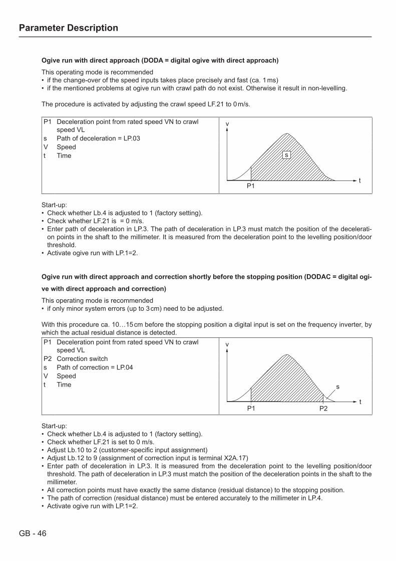
GB - 46
Parameter Description
Ogive run with direct approach (DODA = digital ogive with direct approach)
This operating mode is recommended• if the change-over of the speed inputs takes place precisely and fast (ca. 1 ms)• if the mentioned problems at ogive run with crawl path do not exist. Otherwise it result in non-levelling.
The procedure is activated by adjusting the crawl speed LF.21 to 0 m/s.
P1 Deceleration point from rated speed VN to crawl speed VL
s
t
v
P1
s Path of deceleration = LP.03V Speedt Time
Start-up:• Check whether Lb.4 is adjusted to 1 (factory setting).• Check whether LF.21 is = 0 m/s.• Enter path of deceleration in LP.3. The path of deceleration in LP.3 must match the position of the decelerati-
on points in the shaft to the millimeter. It is measured from the deceleration point to the levelling position/door threshold.
• Activate ogive run with LP.1=2.
Ogive run with direct approach and correction shortly before the stopping position (DODAC = digital ogi-
ve with direct approach and correction)
This operating mode is recommended• if only minor system errors (up to 3 cm) need to be adjusted.
With this procedure ca. 10…15 cm before the stopping position a digital input is set on the frequency inverter, by which the actual residual distance is detected.P1 Deceleration point from rated speed VN to crawl
speed VL
t
v
P1 P2
s
P2 Correction switchs Path of correction = LP.04V Speedt Time
Start-up:• Check whether Lb.4 is adjusted to 1 (factory setting).• Check whether LF.21 is set to 0 m/s.• Adjust Lb.10 to 2 (customer-specific input assignment)• Adjust Lb.12 to 9 (assignment of correction input is terminal X2A.17)• Enter path of deceleration in LP.3. It is measured from the deceleration point to the levelling position/door
threshold. The path of deceleration in LP.3 must match the position of the deceleration points in the shaft to the millimeter.
• All correction points must have exactly the same distance (residual distance) to the stopping position.• The path of correction (residual distance) must be entered accurately to the millimeter in LP.4.• Activate ogive run with LP.1=2.
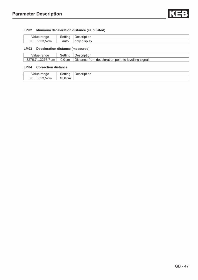
GB - 47
Parameter Description
LP.02 Minimum deceleration distance (calculated)
Value range Setting Description0,0…6553,5 cm auto only display
LP.03 Deceleration distance (measured)
Value range Setting Description-3276,7…3276,7 cm 0,0 cm Distance from deceleration point to levelling signal.
LP.04 Correction distance
Value range Setting Description0,0…6553,5 cm 10,0 cm
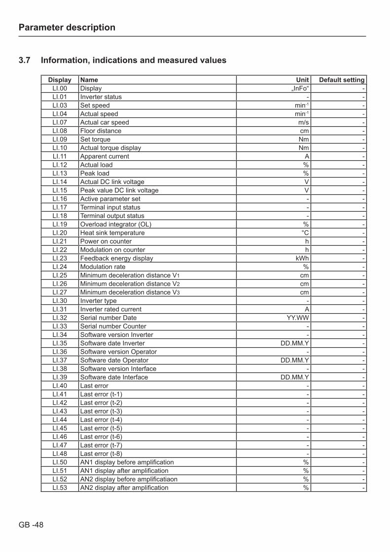
GB -48
Parameter description
3.7 Information, indications and measured values
Display Name Unit Default settingLI.00 Display „InFo“ -LI.01 Inverter status - -LI.03 Set speed min-1 -LI.04 Actual speed min-1 -LI.07 Actual car speed m/s -LI.08 Floor distance cm -LI.09 Set torque Nm -LI.10 Actual torque display Nm -LI.11 Apparent current A -LI.12 Actual load % -LI.13 Peak load % -LI.14 Actual DC link voltage V -LI.15 Peak value DC link voltage V -LI.16 Active parameter set - -LI.17 Terminal input status - -LI.18 Terminal output status - -LI.19 Overload integrator (OL) % -LI.20 Heat sink temperature °C -LI.21 Power on counter h -LI.22 Modulation on counter h -LI.23 Feedback energy display kWh -LI.24 Modulation rate % -LI.25 Minimum deceleration distance V1 cm -LI.26 Minimum deceleration distance V2 cm -LI.27 Minimum deceleration distance V3 cm -LI.30 Inverter type - -LI.31 Inverter rated current A -LI.32 Serial number Date YY.WW -LI.33 Serial number Counter - -LI.34 Software version Inverter - -LI.35 Software date Inverter DD.MM.Y -LI.36 Software version Operator - -LI.37 Software date Operator DD.MM.Y -LI.38 Software version Interface - -LI.39 Software date Interface DD.MM.Y -LI.40 Last error - -LI.41 Last error (t-1) - -LI.42 Last error (t-2) - -LI.43 Last error (t-3) - -LI.44 Last error (t-4) - -LI.45 Last error (t-5) - -LI.46 Last error (t-6) - -LI.47 Last error (t-7) - -LI.48 Last error (t-8) - -LI.50 AN1 display before amplification % -LI.51 AN1 display after amplification % -LI.52 AN2 display before amplificatiaon % -LI.53 AN2 display after amplification % -

GB -49
Parameter description
LI.00 Display of current parameter group „InFo“
LI.01 Inverter status
This parameter shows the current status (e.g. constant run, acceleration counter-clockwise rotation) of the inverter. You find a table of all status and error messages in the annex.
LI.03 Set speed
Display Description0…±4000 rpm Display of the current setpoint value. For control reasons the set speed is also displayed,
if the control release or the direction of rotation is not switched. If no direction of rotation is given, the set speed for clockwise rotation (forward) is displayed.
LI.04 Actual speed
Display Description0…±4000 rpm Display of the current motor speed (encoder channel 1). For control reasons the set speed
is also displayed, if the control release or the direction of rotation is not switched. A counter-clockwise rotating field (reverse) is represented by a negative sign. Precondition for the correct display value is the in-phase connection of the motor and the correct adjustment of the encoder increments as well as the direction of rotation.
LI.07 Actual car speed
Display Description0…±20 m/s Display of the current speed of the lift. For control reasons the actual speed is also
displayed, if the control release or the direction of rotation is not switched. A counter-clockwise rotating field (reverse) is represented by a negative sign. Precondition for the correct display value is the in-phase connection of the motor and the correct basic setting.
LI.08 Floor distance
Display Description±32767 cm Indicates the last travel distance from start to stop.
LI.09 Set torque
Display Description0,00…32000,00 Nm
LI.10 Actual torque display
Display Description0,00…32000,00 Nm The displayed value corresponds to the current motor torque in Nm. The value is calculated
from the active current. Due to common type variations and temperature drifts of the motor tolerances of up to 30 % are possible in the base speed range. Basic requirement for the torque display is the adjustment of the motor data. If the real motor data deviate strongly from the name plate data, the operating performance can be optimized by entering the real data. For the start-up the adjustment of the name plate data is sufficient.
LI.11 Apparent current
Display Description0…1000 A Display of the current motor apparent current.
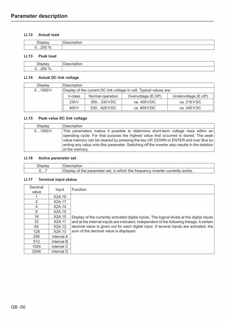
GB -50
Parameter description
LI.12 Actual load
Display Description0…200 %
LI.13 Peak load
Display Description0…200 %
LI.14 Actual DC link voltage
Display Description0…1000 V Display of the current DC link voltage in volt. Typical values are:
V-class Normal operation Overvoltage (E.OP) Undervoltage (E.UP)230 V 300…330 V DC ca. 400 V DC ca. 216 V DC400 V 530…620 V DC ca. 800 V DC ca. 240 V DC
LI.15 Peak value DC link voltage
Display Description0…1000 V This parameters makes it possible to determine short-term voltage rises within an
operating cycle. For that purpose the highest value that occurred is stored. The peak value memory can be cleared by pressing the key UP, DOWN or ENTER and over Bus by writing any value onto this parameter. Switching off the inverter also results in the deletion of the memory.
LI.16 Active parameter set
Display Description0…7 Display of the parameter set, in which the frequency inverter currently works.
LI.17 Terminal input status
Decimal value Input Function
1 X2A.16
Display of the currently activated digital inputs. The logical levels at the digital inputs and at the internal inputs are indicated, independent of the following linkage. A certain decimal value is given out for each digital input. If several inputs are activated, the sum of the decimal value is displayed.
2 X2A.174 X2A.148 X2A.15
16 X2A.1032 X2A.1164 X2A.12128 X2A.13256 internal A512 internal B1024 internal C2048 internal D

GB -51
Parameter description
LI.18 Terminal output status
Decimal value Output Function
1 X2A.18
Display of the currently set external and internal digital outputs. A certain value is given out for each digital output. If several outputs are activated, the sum of the decimal value is displayed.
2 X2A.194 X2A.24…268 X2A.27…2916 internal A32 internal B64 internal C128 internal D
LI.19 Overload integrator (OL)
Value range Description0…100 % To prevent overload errors (E.OL) (load reduction in time), the internal meter reading of
the OL-counter can be made visible with this parameter. At 100 % the inverter switches off with error „E.OL“. The error can be reset after a cooling down phase (blinking display „E.nOL“).
LI.20 Heat sink temperature
Value range Description0…150 °C The parameter displays the current heat sink temperature of the inverter.
LI.21 Power on counter
Value range Description0…65535 h The power on counter shows how long the inverter was switched on. The displayed value
includes all operating phases. On reaching the maximum value (ca. 7.5 years) the display stays on the maximum value.
LI.22 Modulation on counter
Value range Description0…65535 h The modulation on counter shows how long the inverter was active (power modules
activated). On reaching the maximum value (ca. 7.5 years) the display stays on the maximum value.
LI.23 Feedback energy display
Value range Description0…65535 kWh Display of the feedback energy during generative operation. On the basis of this value
it can be calculated, whether the use of a regenerative unit could be profitable. For that purpose the actual resistance value of the brake resistor must be entered in Lb.18.
LI.24 Modulation rate
Value range Description0…110 % The modulation rate shows the output voltage in percent. 100% correspond to the input
voltage (unloaded). At a value above 100 % the inverter operates with overmodulation.
LI.25 Minimum deceleration distance V1
Value range Description0,0…6553,5 cm Indicates the calculated deceleration distance for V1.
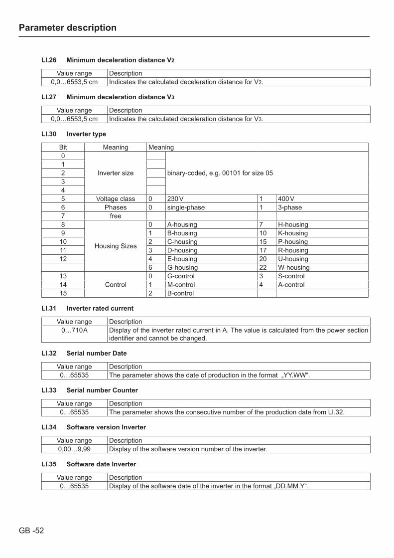
GB -52
Parameter description
LI.26 Minimum deceleration distance V2
Value range Description0,0…6553,5 cm Indicates the calculated deceleration distance for V2.
LI.27 Minimum deceleration distance V3
Value range Description0,0…6553,5 cm Indicates the calculated deceleration distance for V3.
LI.30 Inverter type
Bit Meaning Meaning0
Inverter size binary-coded, e.g. 00101 for size 0512345 Voltage class 0 230 V 1 400 V6 Phases 0 single-phase 1 3-phase7 free8
Housing Sizes
0 A-housing 7 H-housing9 1 B-housing 10 K-housing10 2 C-housing 15 P-housing11 3 D-housing 17 R-housing12 4 E-housing 20 U-housing
6 G-housing 22 W-housing13
Control0 G-control 3 S-control
14 1 M-control 4 A-control15 2 B-control
LI.31 Inverter rated current
Value range Description0…710 A Display of the inverter rated current in A. The value is calculated from the power section
identifier and cannot be changed.
LI.32 Serial number Date
Value range Description0…65535 The parameter shows the date of production in the format „YY.WW“.
LI.33 Serial number Counter
Value range Description0…65535 The parameter shows the consecutive number of the production date from LI.32.
LI.34 Software version Inverter
Value range Description0,00…9,99 Display of the software version number of the inverter.
LI.35 Software date Inverter
Value range Description0…65535 Display of the software date of the inverter in the format „DD.MM.Y“.
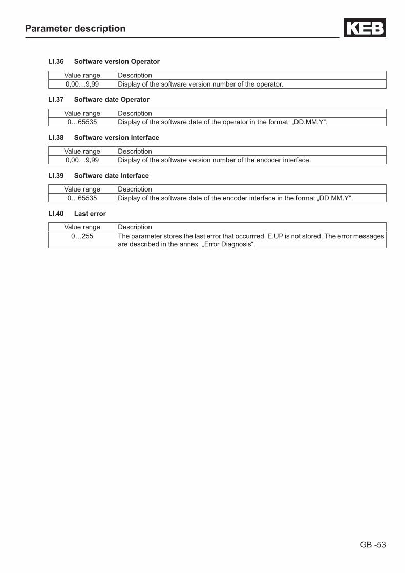
GB -53
Parameter description
LI.36 Software version Operator
Value range Description0,00…9,99 Display of the software version number of the operator.
LI.37 Software date Operator
Value range Description0…65535 Display of the software date of the operator in the format „DD.MM.Y“.
LI.38 Software version Interface
Value range Description0,00…9,99 Display of the software version number of the encoder interface.
LI.39 Software date Interface
Value range Description0…65535 Display of the software date of the encoder interface in the format „DD.MM.Y“.
LI.40 Last error
Value range Description0…255 The parameter stores the last error that occurrred. E.UP is not stored. The error messages
are described in the annex „Error Diagnosis“.
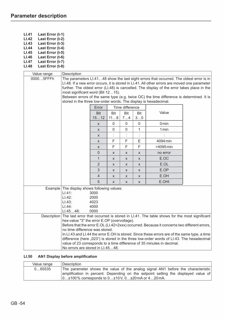
GB -54
Parameter description
LI.41 Last Error (t-1)LI.42 Last Error (t-2)LI.43 Last Error (t-3)LI.44 Last Error (t-4)LI.45 Last Error (t-5)LI.46 Last Error (t-6)LI.47 Last Error (t-7)LI.48 Last Error (t-8)
Value range Description0000…5FFFh The parameters LI.41…48 show the last eight errors that occurred. The oldest error is in
LI.48. If a new error occurs, it is stored in LI.41. All other errors are moved one parameter further. The oldest error (LI.48) is cancelled. The display of the error takes place in the most significant word (Bit 12…15).Between errors of the same type (e.g. twice OC) the time difference is determined. It is stored in the three low-order words. The display is hexadecimal.
Error Time differenceValueBit
15…12Bit
11…8Bit
7…4Bit
3…0x 0 0 0 0 minx 0 0 1 1 minx : : : :x F F E 4094 minx F F F >4095 min0 x x x no error1 x x x E.OC2 x x x E.OL3 x x x E.OP4 x x x E.OH5 x x x E.OHI
Example The display shows following values:LI.41: 3000LI.42: 2000LI.43: 4023LI.44: 4000LI.45…48: 0000
Description The last error that occurred is stored in LI.41. The table shows for the most significant hex-value "3" the error E.OP (overvoltage).Before that the error E.OL (LI.42=2xxx) occurred. Because it concerns two different errors, no time difference was stored.In LI.43 and LI.44 the error E.OH is stored. Since these errors are of the same type, a time difference (here „023“) is stored in the three low-order words of LI.43. The hexadecimal value of 23 corresponds to a time difference of 35 minutes in decimal.No errors are stored in LI.45…48.
LI.50 AN1Displaybeforeamplification
Value range Description0…65535 The parameter shows the value of the analog signal AN1 before the characteristic
amplification in percent. Depending on the setpoint setting the displayed value of 0…±100 % corresponds to 0…±10 V, 0…±20 mA or 4…20 mA.

GB -55
Parameter description
LI.51 AN1Displayafteramplification
Value range Description0…±400 % The parameter shows the value of the analog signal AN1 after running through the
characteristic amplification in percent. The value range is limited to ±400 %.
LI.52 AN2Displaybeforeamplification
Value range Description0…±100 % The parameter shows the value of the analog signal AN2 before the characteristic
amplification in percent. Depending on the setpoint setting the displayed value of 0…±100 % corresponds to 0…±10 V, 0…±20 mA or 4…20 mA.
LI.53 AN2Displayafteramplification
Value range Description0…±400 % The parameter shows the value of the analog signal AN2 after running through the
characteristic amplification in percent. The value range is limited to ±400 %.

GB - 56
Parameter description
3.8 Adjustment of analog inputs and outputs
Display Name Setting Range Default settingLA.00 Display „AnLog“ -LA.01 AN1 setpoint selection 0…2 0LA.02 AN1 interference filter 0…4 0LA.03 AN1 zero point hysteresis 0…±10 V 0,2 VLA.04 AN1 amplification 0,00…±20,00 1,00LA.05 AN1 Offset X 0,0…±100,0 % 0,0 %LA.06 AN1 Offset Y 0,0…±100,0 % 0,0 %LA.07 AN1 lower limit 0,0…±400,0 % -400,0 %LA.08 AN1 upper limit 0,0…±400,0 % 400,0 %LA.09 AN2 setpoint selection 0…2 0LA.10 AN2 interference filter 0…4 0LA.11 AN2 zero point hysteresis 0…±10 V 0,2 VLA.12 AN2 amplification 0,00…±20,00 1,00LA.13 AN2 Offset X 0,0…±100,0 % 0,0 %LA.14 AN2 Offset Y 0,0…±100,0 % 0,0 %LA.15 AN2 lower limit 0,0…±400,0 % -400,0 %LA.16 AN2 upper limit 0,0…±400,0 % 400,0 %LA.17 Selection REF-input/AUX-function 32768 2112LA.23 Rope weight 0…500 kg 0
LA.00 Display of the current parameter group „AnLog“
LA.01 AN1 Setpoint selection
Input Setting Signal Description0 x 0…±10 V
Depending on the setting the analog input can process the listed setpoint signals.1 0…±20 mA
2 4…20 mA
LA.02 AN1Interferencefilter
Input Setting Average value from
Description
0 x noneA query of the analog signal takes place every millisecond. The interference filter shall suppress interferences and ripples of the input signal, by forming the average value from 2, 4, 8 or 16 scanned values for further processing.
1 2 values2 4 values3 8 values4 16 values
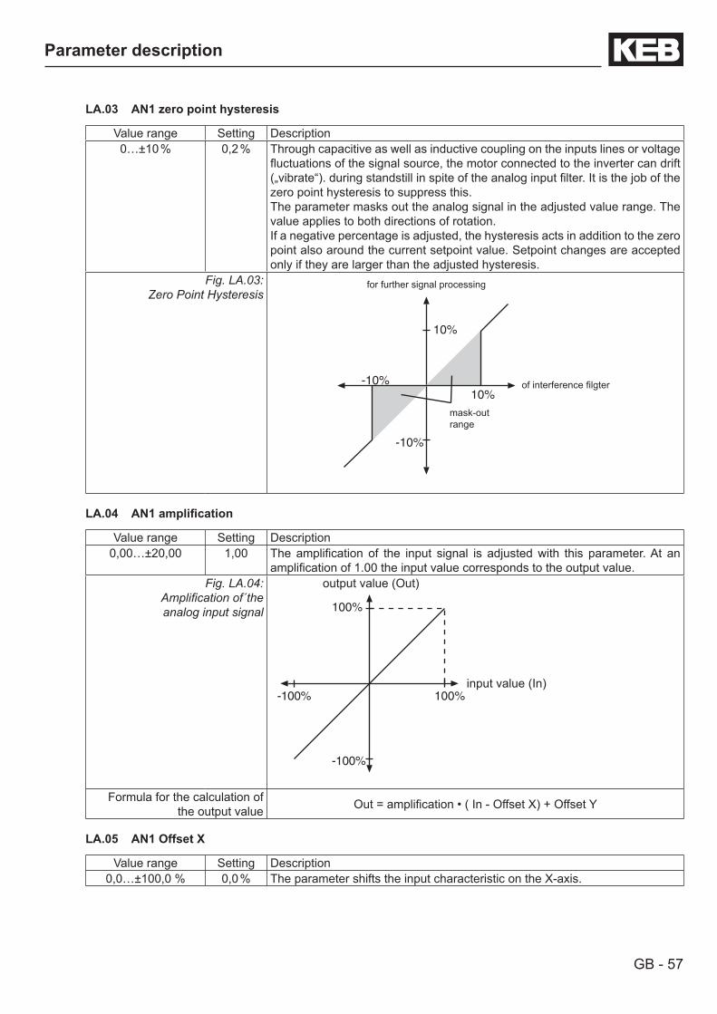
GB - 57
Parameter description
LA.03 AN1 zero point hysteresis
Value range Setting Description0…±10 % 0,2 % Through capacitive as well as inductive coupling on the inputs lines or voltage
fluctuations of the signal source, the motor connected to the inverter can drift („vibrate“). during standstill in spite of the analog input filter. It is the job of the zero point hysteresis to suppress this. The parameter masks out the analog signal in the adjusted value range. The value applies to both directions of rotation.If a negative percentage is adjusted, the hysteresis acts in addition to the zero point also around the current setpoint value. Setpoint changes are accepted only if they are larger than the adjusted hysteresis.
Fig. LA.03: Zero Point Hysteresis
-10%10%
10%
-10%
mask-outrange
of interference filgter
for further signal processing
LA.04 AN1amplification
Value range Setting Description0,00…±20,00 1,00 The amplification of the input signal is adjusted with this parameter. At an
amplification of 1.00 the input value corresponds to the output value.Fig. LA.04:
Amplification of´the analog input signal 100%
100%
-100%
-100%input value (In)
output value (Out)
Formula for the calculation of the output value Out = amplification • ( In - Offset X) + Offset Y
LA.05 AN1 Offset X
Value range Setting Description0,0…±100,0 % 0,0 % The parameter shifts the input characteristic on the X-axis.
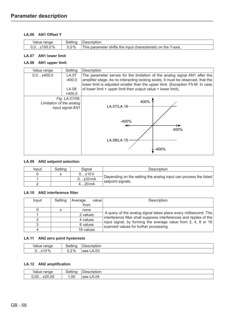
GB - 58
Parameter description
LA.06 AN1 Offset Y
Value range Setting Description0,0…±100,0 % 0,0 % This parameter shifts the input characteristic on the Y-axis.
LA.07 AN1 lower limit
LA.08 AN1 upper limit
Value range Setting Description0,0…±400,0 LA.07
-400,0
LA.08+400,0
The parameter serves for the limitation of the analog signal AN1 after the amplifier stage. As no interacting locking exists, it must be observed, that the lower limit is adjusted smaller than the upper limit. (Exception F5-M: In case of lower limit > upper limit then output value = lower limit).
Fig. LA.07/08:Limitation of the analog
input signal AN1400%
400%
-400%
-400%
LA.07/LA.16
LA.08/LA.15
LA.09 AN2 setpoint selection
Input Setting Signal Description0 x 0…±10 V
Depending on the setting the analog input can process the listed setpoint signals.1 0…±20 mA
2 4…20 mA
LA.10 AN2interferencefilter
Input Setting Average value from
Description
0 x none A query of the analog signal takes place every millisecond. The interference filter shall suppress interferences and ripples of the input signal, by forming the average value from 2, 4, 8 or 16 scanned values for further processing.
1 2 values2 4 values3 8 values4 16 values
LA.11 AN2 zero point hysteresis
Value range Setting Description0…±10 % 0,2 % see LA.03
LA.12 AN2amplification
Value range Setting Description0,00…±20,00 1,00 see LA.04
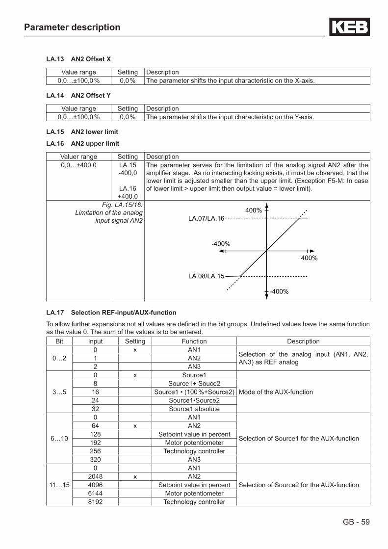
GB - 59
Parameter description
LA.13 AN2 Offset X
Value range Setting Description0,0…±100,0 % 0,0 % The parameter shifts the input characteristic on the X-axis.
LA.14 AN2 Offset Y
Value range Setting Description0,0…±100,0 % 0,0 % The parameter shifts the input characteristic on the Y-axis.
LA.15 AN2 lower limit
LA.16 AN2 upper limit
Valuer range Setting Description0,0…±400,0 LA.15
-400,0
LA.16+400,0
The parameter serves for the limitation of the analog signal AN2 after the amplifier stage. As no interacting locking exists, it must be observed, that the lower limit is adjusted smaller than the upper limit. (Exception F5-M: In case of lower limit > upper limit then output value = lower limit).
Fig. LA.15/16:Limitation of the analog
input signal AN2400%
400%
-400%
-400%
LA.07/LA.16
LA.08/LA.15
LA.17 Selection REF-input/AUX-function
To allow further expansions not all values are defined in the bit groups. Undefined values have the same function as the value 0. The sum of the values is to be entered.
Bit Input Setting Function Description
0…20 x AN1
Selection of the analog input (AN1, AN2, AN3) as REF analog1 AN2
2 AN3
3…5
0 x Source1
Mode of the AUX-function8 Source1+ Souce2
16 Source1 • (100 %+Source2)24 Source1•Source232 Source1 absolute
6…10
0 AN1
Selection of Source1 for the AUX-function
64 x AN2128 Setpoint value in percent192 Motor potentiometer256 Technology controller320 AN3
11…15
0 AN1
Selection of Source2 for the AUX-function2048 x AN24096 Setpoint value in percent6144 Motor potentiometer8192 Technology controller

GB - 60
Parameter description
3.9 Adjustment of pretorque function
1) Preparations• Enter motor data • Connect load weighing equipment to X2A.3 and X2A.4 • Switch on the pretorque with Lb.7 =1• Drive the cabine to the middle of the shaft• Remain at the same position in the shaft when carrying out the measurements• Carry out measurements during standstill of the motor after the brake has released• Adjust the brake release time to 3 s to get a better measurement
2) Measurement with empty cabine• Measure the signal of the load weighing equipment with LI.52. This value „L1“ is displayed in percent.• Measure the torque including the sign with LI.10.• Calculate the torque "T1" in percent according to formula: T1 = LI.10 • 100 / motor rated torque.
3) Measurement with 100% load in the cabine• Measure the signal of the load weighing equipment with LI.52. This value „L2“ is displayed in percent.• Measure the torque including the sign with LI.10.• Calculate the torque "T2" in percent according to formula: T2 = LI.10 • 100 / motor rated torque.
4) Calculate the amplification according to formula LA.12 = (T1-T2)/(L1-L2).
5) Calculate the Offset according to formula LA.14 = LA.12•L1-T1.
6) Enter the caluculated values in LA.12 and LA.14.
Examples
Example 1: Payload 2000 kgSpeed 1 m/sMotor rated torque 1200 NmCounterweight balance 50 %
Empty cabine LI.52 = L1 = 0 % (0 V) LI.10 = +1200 Nm T1 = +100 %Full cabine LI.52 = L2 = 100 % (10 V) LI.10 = -1200 Nm T2 = -100 %
Gain LA.12 = (100 %-(-100 %))/(0 %-100 %) = -2Offset LA.14 = -2•0 %-100 % = -100 %
Example 2: Payload 2000 kgSpeed 1 m/sMotor rated torque 1000 NmCounterweight balance 45 %Load weighing signal has an Offset of -0,5 V and can give out only 8 V at 100 %.
Empty cabine LI.52 = L1 = -5 % (-0,5 V) LI.10 = 1080 Nm T1 = +108 %Full cabine LI.52 = L2 = 80 % (+8 V) LI.10 = -1320 Nm T2 = -132 %
Gain LA.12 = (108 %-(-132 %))/(-5 %-80 %) = -2,82Offset LA.14 = -2,82•(-5 %)-108 % = -93,9 %
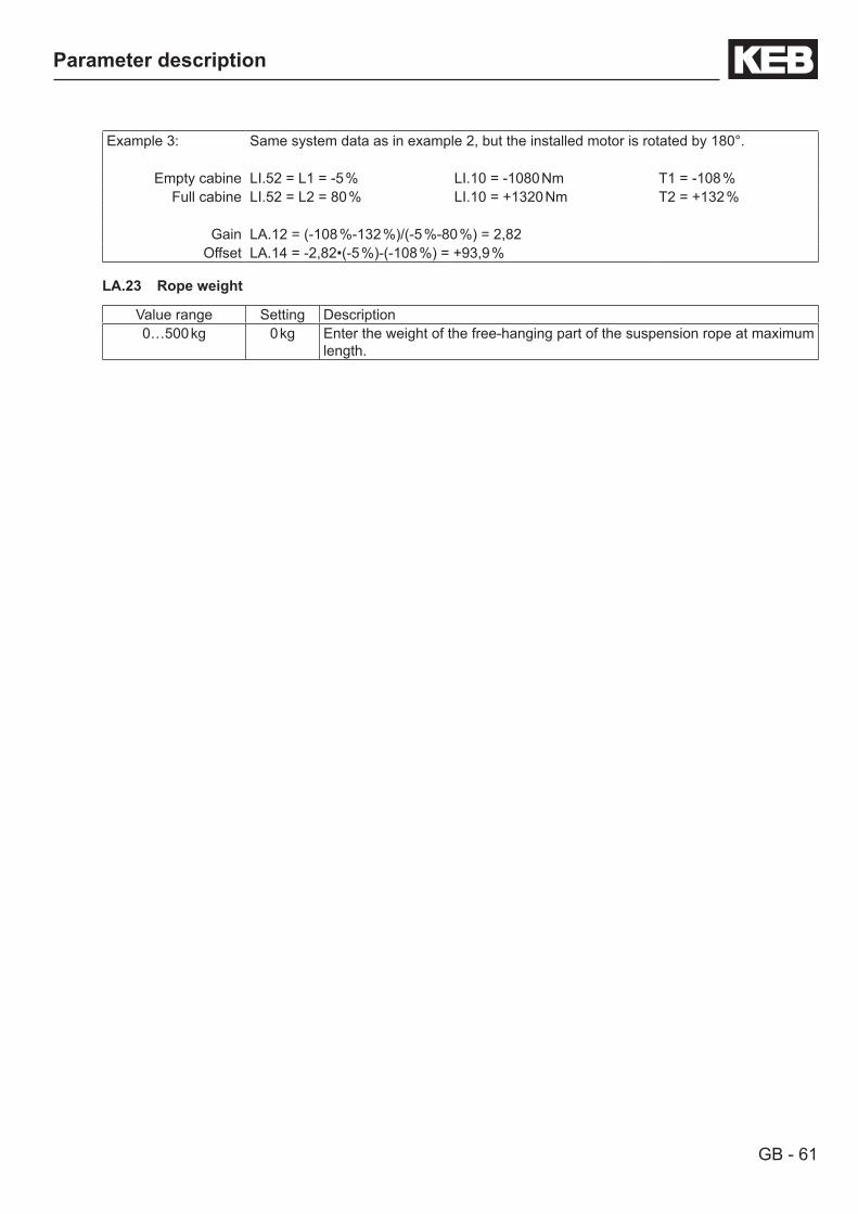
GB - 61
Parameter description
Example 3: Same system data as in example 2, but the installed motor is rotated by 180°.
Empty cabine LI.52 = L1 = -5 % LI.10 = -1080 Nm T1 = -108 %Full cabine LI.52 = L2 = 80 % LI.10 = +1320 Nm T2 = +132 %
Gain LA.12 = (-108 %-132 %)/(-5 %-80 %) = 2,82Offset LA.14 = -2,82•(-5 %)-(-108 %) = +93,9 %
LA.23 Rope weight
Value range Setting Description0…500 kg 0 kg Enter the weight of the free-hanging part of the suspension rope at maximum
length.
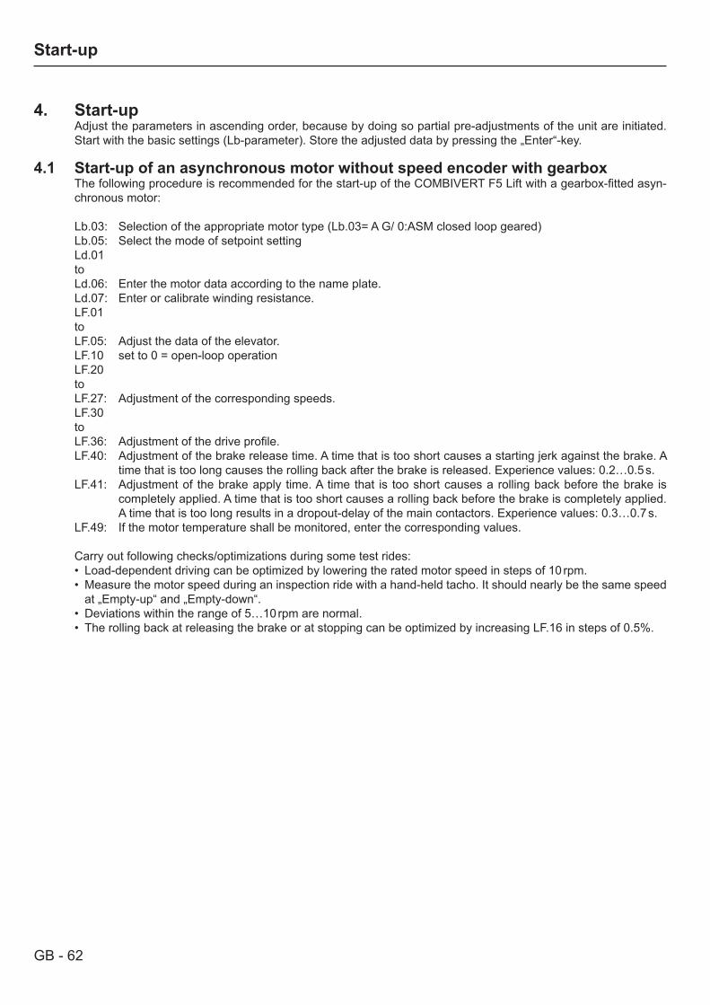
GB - 62
Start-up
4. Start-upAdjust the parameters in ascending order, because by doing so partial pre-adjustments of the unit are initiated. Start with the basic settings (Lb-parameter). Store the adjusted data by pressing the „Enter“-key.
4.1 Start-up of an asynchronous motor without speed encoder with gearbox The following procedure is recommended for the start-up of the COMBIVERT F5 Lift with a gearbox-fitted asyn-chronous motor:
Lb.03: Selection of the appropriate motor type (Lb.03= A G/ 0:ASM closed loop geared)Lb.05: Select the mode of setpoint settingLd.01toLd.06: Enter the motor data according to the name plate.Ld.07: Enter or calibrate winding resistance.LF.01 to LF.05: Adjust the data of the elevator.LF.10 set to 0 = open-loop operationLF.20 to LF.27: Adjustment of the corresponding speeds.LF.30 to LF.36: Adjustment of the drive profile.LF.40: Adjustment of the brake release time. A time that is too short causes a starting jerk against the brake. A
time that is too long causes the rolling back after the brake is released. Experience values: 0.2…0.5 s.LF.41: Adjustment of the brake apply time. A time that is too short causes a rolling back before the brake is
completely applied. A time that is too short causes a rolling back before the brake is completely applied. A time that is too long results in a dropout-delay of the main contactors. Experience values: 0.3…0.7 s.
LF.49: If the motor temperature shall be monitored, enter the corresponding values.
Carry out following checks/optimizations during some test rides:• Load-dependent driving can be optimized by lowering the rated motor speed in steps of 10 rpm.• Measure the motor speed during an inspection ride with a hand-held tacho. It should nearly be the same speed
at „Empty-up“ and „Empty-down“.• Deviations within the range of 5…10 rpm are normal.• The rolling back at releasing the brake or at stopping can be optimized by increasing LF.16 in steps of 0.5%.

GB - 63
Start-up
4.2 Start-up of an asynchronous motor with speed encoder and gearbox
Lb.03: Selection of the appropriate motor type (Lb.03= AG/ 0: ASM closed loop geared)Lb.05: Select the mode of setpoint settingLd.01toLd.06: Enter the motor data according to the name plate.Ld.11: If necessary, limit the maximum torque for normal operation.Ld.20: Possible limitation of the maximum torque for UPS operation, to protect the UPS (uninterruptible power
supple) against overload..LC.12: Adjust the increments per revolution of the motor encoder.LF.01 to LF.05: Adjust the data of the elevator.LF.20 to LF.27: Adjustment of the corresponding speeds.LF.30 to LF.36: Adjustment of the drive profile.LF.40: Adjustment of the brake release time. A time that is too short causes a starting jerk against the brake. A
time that is too long causes the rolling back after the brake is released. Experience values: 0.2…0.5 s.LF.41: Adjustment of the brake apply time. A time that is too short causes a rolling back before the brake is
completely applied. A time that is too long results in a dropout-delay of the main contactors. Experience values: 0.3…0.7 s.
LF.49: If the motor temperature shall be monitored, enter the corresponding value.
Carry out following checks/optimizations during some test rides:• Is the desired travel direction (up/down) maintained ?• Compare setpoint speed LI.03 with actual speed LI.04. The sign of both speed displays in the same travel di-
rection must be the same (positive is not displayed). If the sign is not equal, an encoder track change must be made with LC.13. In addition to that the travel direction can also be changed:
• Optimization of the load transfer by increasing LF.13 in steps of 500, if the drive turns away too much on relea-sing the brake.
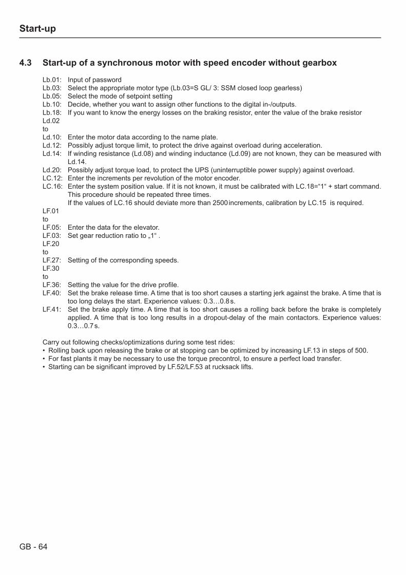
GB - 64
Start-up
4.3 Start-up of a synchronous motor with speed encoder without gearbox
Lb.01: Input of passwordLb.03: Select the appropriate motor type (Lb.03=S GL/ 3: SSM closed loop gearless)Lb.05: Select the mode of setpoint settingLb.10: Decide, whether you want to assign other functions to the digital in-/outputs.Lb.18: If you want to know the energy losses on the braking resistor, enter the value of the brake resistorLd.02toLd.10: Enter the motor data according to the name plate.Ld.12: Possibly adjust torque limit, to protect the drive against overload during acceleration.Ld.14: If winding resistance (Ld.08) and winding inductance (Ld.09) are not known, they can be measured with
Ld.14.Ld.20: Possibly adjust torque load, to protect the UPS (uninterruptible power supply) against overload.LC.12: Enter the increments per revolution of the motor encoder.LC.16: Enter the system position value. If it is not known, it must be calibrated with LC.18=“1“ + start command.
This procedure should be repeated three times. If the values of LC.16 should deviate more than 2500 increments, calibration by LC.15 is required.LF.01to LF.05: Enter the data for the elevator.LF.03: Set gear reduction ratio to „1“ .LF.20toLF.27: Setting of the corresponding speeds.LF.30toLF.36: Setting the value for the drive profile.LF.40: Set the brake release time. A time that is too short causes a starting jerk against the brake. A time that is
too long delays the start. Experience values: 0.3…0.8 s.LF.41: Set the brake apply time. A time that is too short causes a rolling back before the brake is completely
applied. A time that is too long results in a dropout-delay of the main contactors. Experience values: 0.3…0.7 s.
Carry out following checks/optimizations during some test rides:• Rolling back upon releasing the brake or at stopping can be optimized by increasing LF.13 in steps of 500.• For fast plants it may be necessary to use the torque precontrol, to ensure a perfect load transfer.• Starting can be significant improved by LF.52/LF.53 at rucksack lifts.
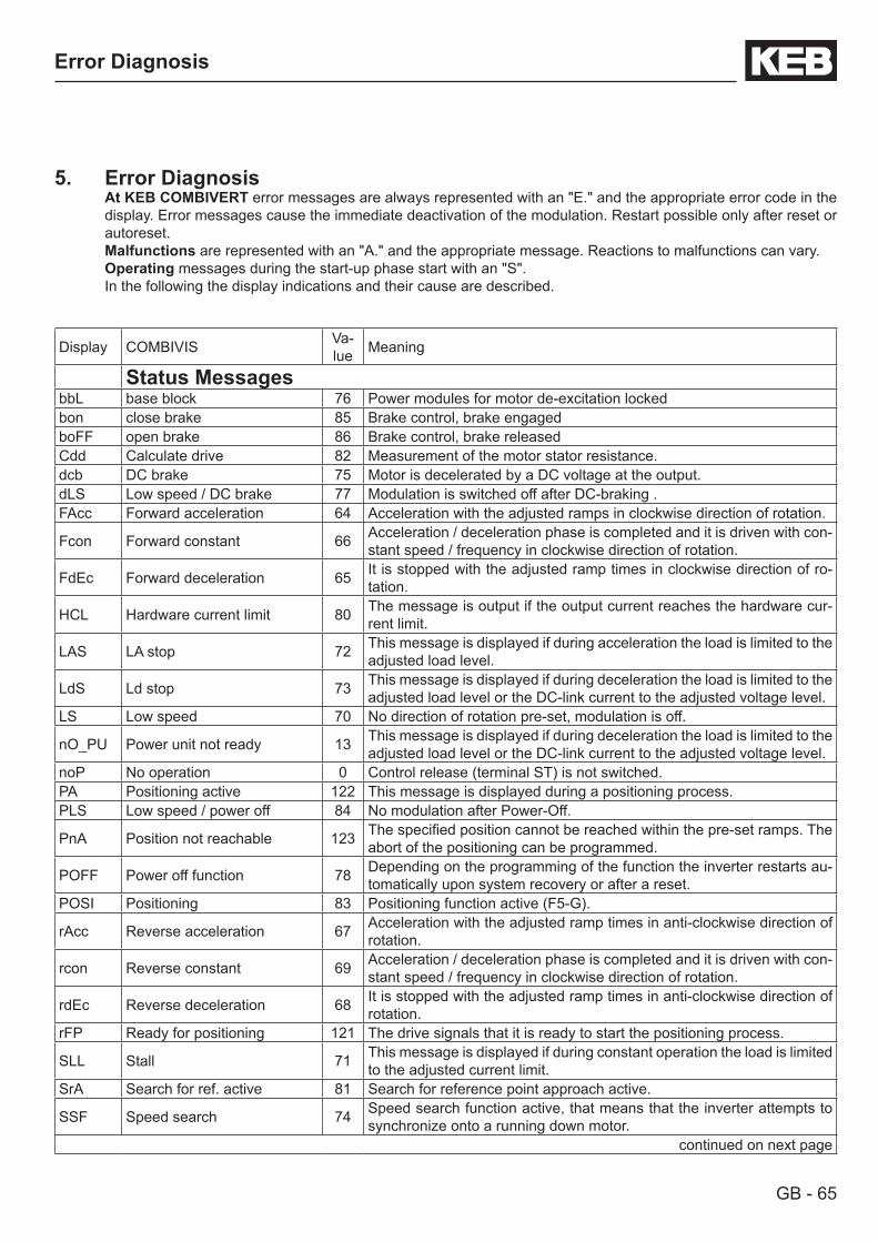
GB - 65
Error Diagnosis
5. Error DiagnosisAt KEB COMBIVERT error messages are always represented with an "E." and the appropriate error code in the display. Error messages cause the immediate deactivation of the modulation. Restart possible only after reset or autoreset.Malfunctions are represented with an "A." and the appropriate message. Reactions to malfunctions can vary.Operating messages during the start-up phase start with an "S".In the following the display indications and their cause are described.
Display COMBIVIS Va-lue Meaning
Status MessagesbbL base block 76 Power modules for motor de-excitation lockedbon close brake 85 Brake control, brake engaged boFF open brake 86 Brake control, brake releasedCdd Calculate drive 82 Measurement of the motor stator resistance.dcb DC brake 75 Motor is decelerated by a DC voltage at the output.dLS Low speed / DC brake 77 Modulation is switched off after DC-braking .FAcc Forward acceleration 64 Acceleration with the adjusted ramps in clockwise direction of rotation.
Fcon Forward constant 66 Acceleration / deceleration phase is completed and it is driven with con-stant speed / frequency in clockwise direction of rotation.
FdEc Forward deceleration 65 It is stopped with the adjusted ramp times in clockwise direction of ro-tation.
HCL Hardware current limit 80 The message is output if the output current reaches the hardware cur-rent limit.
LAS LA stop 72 This message is displayed if during acceleration the load is limited to the adjusted load level.
LdS Ld stop 73 This message is displayed if during deceleration the load is limited to the adjusted load level or the DC-link current to the adjusted voltage level.
LS Low speed 70 No direction of rotation pre-set, modulation is off.
nO_PU Power unit not ready 13 This message is displayed if during deceleration the load is limited to the adjusted load level or the DC-link current to the adjusted voltage level.
noP No operation 0 Control release (terminal ST) is not switched.PA Positioning active 122 This message is displayed during a positioning process.PLS Low speed / power off 84 No modulation after Power-Off.
PnA Position not reachable 123 The specified position cannot be reached within the pre-set ramps. The abort of the positioning can be programmed.
POFF Power off function 78 Depending on the programming of the function the inverter restarts au-tomatically upon system recovery or after a reset.
POSI Positioning 83 Positioning function active (F5-G).
rAcc Reverse acceleration 67 Acceleration with the adjusted ramp times in anti-clockwise direction of rotation.
rcon Reverse constant 69 Acceleration / deceleration phase is completed and it is driven with con-stant speed / frequency in clockwise direction of rotation.
rdEc Reverse deceleration 68 It is stopped with the adjusted ramp times in anti-clockwise direction of rotation.
rFP Ready for positioning 121 The drive signals that it is ready to start the positioning process.
SLL Stall 71 This message is displayed if during constant operation the load is limited to the adjusted current limit.
SrA Search for ref. active 81 Search for reference point approach active.
SSF Speed search 74 Speed search function active, that means that the inverter attempts to synchronize onto a running down motor.
continued on next page
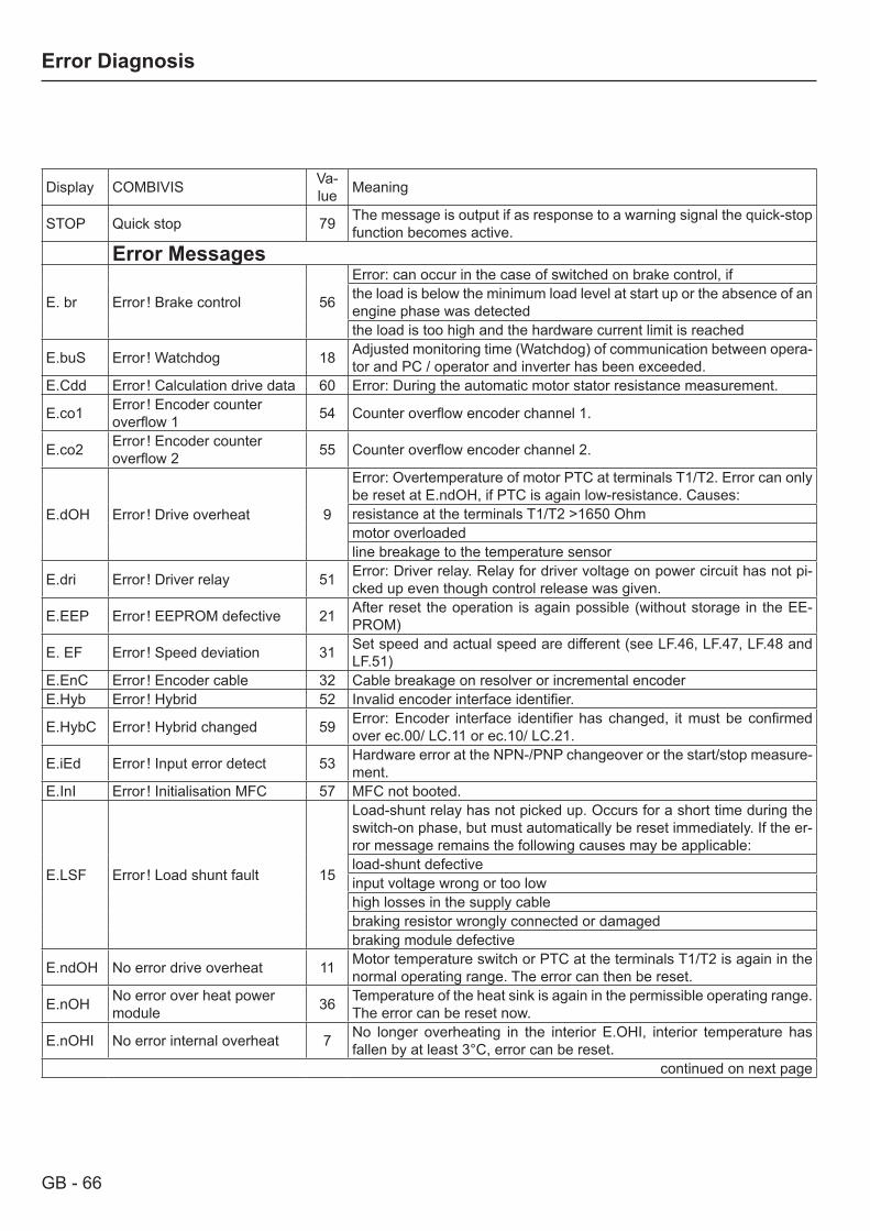
GB - 66
Error Diagnosis
Display COMBIVIS Va-lue Meaning
STOP Quick stop 79 The message is output if as response to a warning signal the quick-stop function becomes active.
Error Messages
E. br Error ! Brake control 56
Error: can occur in the case of switched on brake control, ifthe load is below the minimum load level at start up or the absence of an engine phase was detectedthe load is too high and the hardware current limit is reached
E.buS Error ! Watchdog 18 Adjusted monitoring time (Watchdog) of communication between opera-tor and PC / operator and inverter has been exceeded.
E.Cdd Error ! Calculation drive data 60 Error: During the automatic motor stator resistance measurement.
E.co1 Error ! Encoder counter overflow 1 54 Counter overflow encoder channel 1.
E.co2 Error ! Encoder counter overflow 2 55 Counter overflow encoder channel 2.
E.dOH Error ! Drive overheat 9
Error: Overtemperature of motor PTC at terminals T1/T2. Error can only be reset at E.ndOH, if PTC is again low-resistance. Causes:resistance at the terminals T1/T2 >1650 Ohmmotor overloadedline breakage to the temperature sensor
E.dri Error ! Driver relay 51 Error: Driver relay. Relay for driver voltage on power circuit has not pi-cked up even though control release was given.
E.EEP Error ! EEPROM defective 21 After reset the operation is again possible (without storage in the EE-PROM)
E. EF Error ! Speed deviation 31 Set speed and actual speed are different (see LF.46, LF.47, LF.48 and LF.51)
E.EnC Error ! Encoder cable 32 Cable breakage on resolver or incremental encoderE.Hyb Error ! Hybrid 52 Invalid encoder interface identifier.
E.HybC Error ! Hybrid changed 59 Error: Encoder interface identifier has changed, it must be confirmed over ec.00/ LC.11 or ec.10/ LC.21.
E.iEd Error ! Input error detect 53 Hardware error at the NPN-/PNP changeover or the start/stop measure-ment.
E.InI Error ! Initialisation MFC 57 MFC not booted.
E.LSF Error ! Load shunt fault 15
Load-shunt relay has not picked up. Occurs for a short time during the switch-on phase, but must automatically be reset immediately. If the er-ror message remains the following causes may be applicable:load-shunt defectiveinput voltage wrong or too lowhigh losses in the supply cablebraking resistor wrongly connected or damagedbraking module defective
E.ndOH No error drive overheat 11 Motor temperature switch or PTC at the terminals T1/T2 is again in the normal operating range. The error can then be reset.
E.nOH No error over heat power module 36 Temperature of the heat sink is again in the permissible operating range.
The error can be reset now.
E.nOHI No error internal overheat 7 No longer overheating in the interior E.OHI, interior temperature has fallen by at least 3°C, error can be reset.
continued on next page
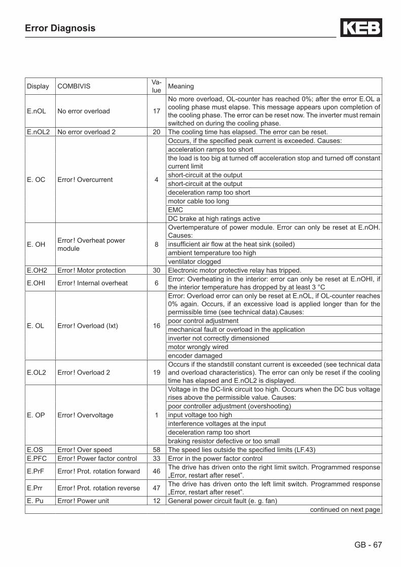
GB - 67
Error Diagnosis
Display COMBIVIS Va-lue Meaning
E.nOL No error overload 17
No more overload, OL-counter has reached 0%; after the error E.OL a cooling phase must elapse. This message appears upon completion of the cooling phase. The error can be reset now. The inverter must remain switched on during the cooling phase.
E.nOL2 No error overload 2 20 The cooling time has elapsed. The error can be reset.
E. OC Error ! Overcurrent 4
Occurs, if the specified peak current is exceeded. Causes:acceleration ramps too shortthe load is too big at turned off acceleration stop and turned off constant current limitshort-circuit at the outputshort-circuit at the outputdeceleration ramp too shortmotor cable too longEMCDC brake at high ratings active
E. OH Error ! Overheat power module 8
Overtemperature of power module. Error can only be reset at E.nOH. Causes:insufficient air flow at the heat sink (soiled)ambient temperature too highventilator clogged
E.OH2 Error ! Motor protection 30 Electronic motor protective relay has tripped.
E.OHI Error ! Internal overheat 6 Error: Overheating in the interior: error can only be reset at E.nOHI, if the interior temperature has dropped by at least 3 °C
E. OL Error ! Overload (Ixt) 16
Error: Overload error can only be reset at E.nOL, if OL-counter reaches 0% again. Occurs, if an excessive load is applied longer than for the permissible time (see technical data).Causes:poor control adjustment mechanical fault or overload in the applicationinverter not correctly dimensionedmotor wrongly wiredencoder damaged
E.OL2 Error ! Overload 2 19Occurs if the standstill constant current is exceeded (see technical data and overload characteristics). The error can only be reset if the cooling time has elapsed and E.nOL2 is displayed.
E. OP Error ! Overvoltage 1
Voltage in the DC-link circuit too high. Occurs when the DC bus voltage rises above the permissible value. Causes:poor controller adjustment (overshooting)input voltage too highinterference voltages at the inputdeceleration ramp too shortbraking resistor defective or too small
E.OS Error ! Over speed 58 The speed lies outside the specified limits (LF.43)E.PFC Error ! Power factor control 33 Error in the power factor control
E.PrF Error ! Prot. rotation forward 46 The drive has driven onto the right limit switch. Programmed response „Error, restart after reset”.
E.Prr Error ! Prot. rotation reverse 47 The drive has driven onto the left limit switch. Programmed response „Error, restart after reset”.
E. Pu Error ! Power unit 12 General power circuit fault (e. g. fan)continued on next page
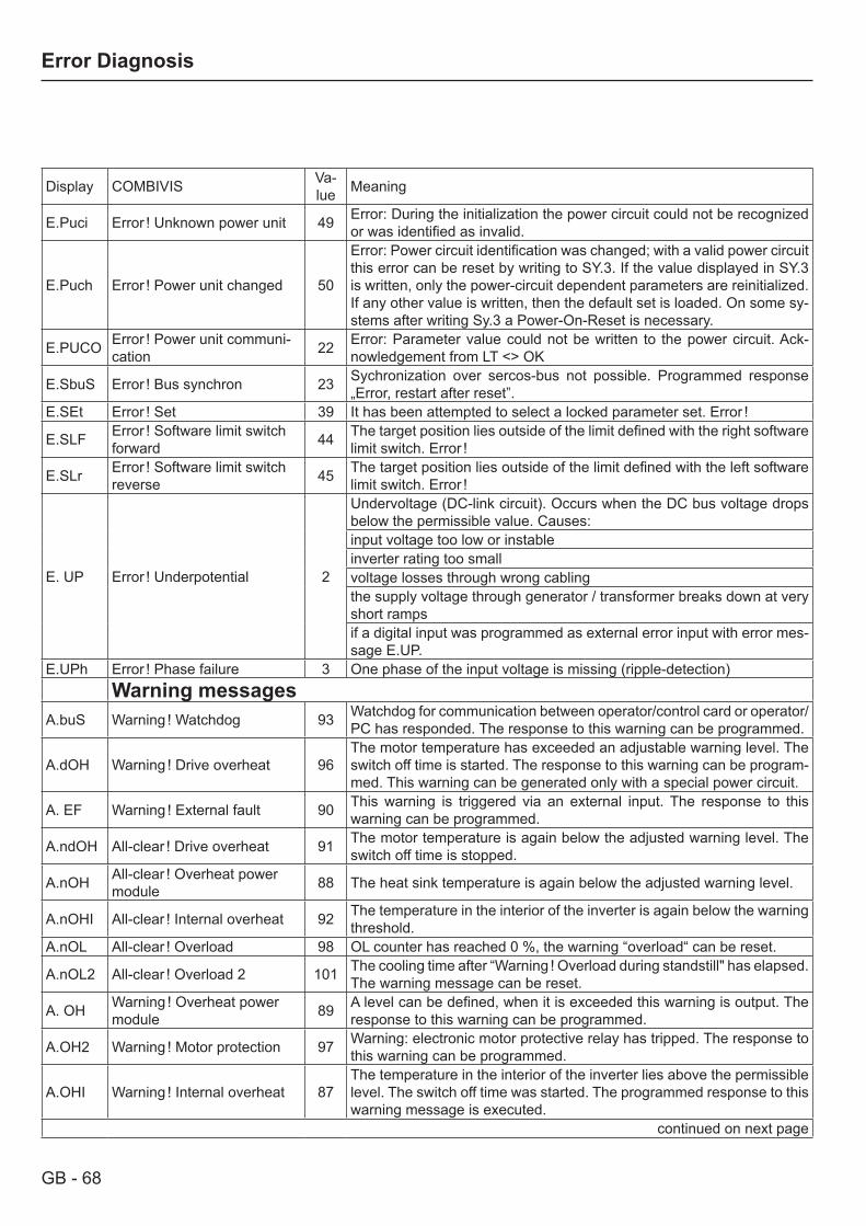
GB - 68
Error Diagnosis
Display COMBIVIS Va-lue Meaning
E.Puci Error ! Unknown power unit 49 Error: During the initialization the power circuit could not be recognized or was identified as invalid.
E.Puch Error ! Power unit changed 50
Error: Power circuit identification was changed; with a valid power circuit this error can be reset by writing to SY.3. If the value displayed in SY.3 is written, only the power-circuit dependent parameters are reinitialized. If any other value is written, then the default set is loaded. On some sy-stems after writing Sy.3 a Power-On-Reset is necessary.
E.PUCO Error ! Power unit communi-cation 22 Error: Parameter value could not be written to the power circuit. Ack-
nowledgement from LT <> OK
E.SbuS Error ! Bus synchron 23 Sychronization over sercos-bus not possible. Programmed response „Error, restart after reset”.
E.SEt Error ! Set 39 It has been attempted to select a locked parameter set. Error !
E.SLF Error ! Software limit switch forward 44 The target position lies outside of the limit defined with the right software
limit switch. Error !
E.SLr Error ! Software limit switch reverse 45 The target position lies outside of the limit defined with the left software
limit switch. Error !
E. UP Error ! Underpotential 2
Undervoltage (DC-link circuit). Occurs when the DC bus voltage drops below the permissible value. Causes:input voltage too low or instableinverter rating too smallvoltage losses through wrong cablingthe supply voltage through generator / transformer breaks down at very short rampsif a digital input was programmed as external error input with error mes-sage E.UP.
E.UPh Error ! Phase failure 3 One phase of the input voltage is missing (ripple-detection)Warning messages
A.buS Warning ! Watchdog 93 Watchdog for communication between operator/control card or operator/PC has responded. The response to this warning can be programmed.
A.dOH Warning ! Drive overheat 96The motor temperature has exceeded an adjustable warning level. The switch off time is started. The response to this warning can be program-med. This warning can be generated only with a special power circuit.
A. EF Warning ! External fault 90 This warning is triggered via an external input. The response to this warning can be programmed.
A.ndOH All-clear ! Drive overheat 91 The motor temperature is again below the adjusted warning level. The switch off time is stopped.
A.nOH All-clear ! Overheat power module 88 The heat sink temperature is again below the adjusted warning level.
A.nOHI All-clear ! Internal overheat 92 The temperature in the interior of the inverter is again below the warning threshold.
A.nOL All-clear ! Overload 98 OL counter has reached 0 %, the warning “overload“ can be reset.
A.nOL2 All-clear ! Overload 2 101 The cooling time after “Warning ! Overload during standstill" has elapsed. The warning message can be reset.
A. OH Warning ! Overheat power module 89 A level can be defined, when it is exceeded this warning is output. The
response to this warning can be programmed.
A.OH2 Warning ! Motor protection 97 Warning: electronic motor protective relay has tripped. The response to this warning can be programmed.
A.OHI Warning ! Internal overheat 87The temperature in the interior of the inverter lies above the permissible level. The switch off time was started. The programmed response to this warning message is executed.
continued on next page

GB - 69
Error Diagnosis
Display COMBIVIS Va-lue Meaning
A. OL Warning ! Overload 99A level between 0 and 100 % of the load counter can be adjusted, when it is exceeded this warning is output. The response to this warning can be programmed.
A.OL2 Warning ! Overload 2 100
The warning is output when the standstill continuous current is excee-ded (see technical data and overload characteristics). The response to this warning can be programmed. The warning message can only be reset after the cooling time has elapsed and A.nOL2 is displayed.
A.PrF Warning ! Prot. rotation forward 94 The drive has driven onto the right limit switch. The response to this
warning can be programmed.
A.Prr Warning ! Prot. rotation reverse 95 The drive has driven onto the left limit switch. The response to this war-
ning can be programmed.
A.SbuS Warning ! Bus synchron 103 Sychronization over sercos-bus not possible. The response to this war-ning can be programmed.
A.SEt Warning ! Set 102 It has been attempted to select a locked parameter set. The response to this warning can be programmed.
A.SLF Warning ! Software limit switch forward 104 The target position lies outside of the limit defined with the right software
limit switch. The response to this warning can be programmed.
A.SLr Warning ! Software limit switch reverse 105 The target position lies outside of the limit defined with the left software
limit switch. The response to this warning can be programmed.Messages during the start-up phaseS.cc contactor closed 143 Contactor control input not resetS.co contactor open 141 Setpoint selection without contactor control inputS.Ebd both directions 144 Both directions of motion actuated simultaneouslyS.Ebr Error brake 142 Brake does not releaseS.io illegal operation 140 Setpoint selection without control releaseOther messagesidata invalid data Adjustments unknown. Select correct adjustment with "Up/ Down"
keys.

GB - 70
Error Diagnosis
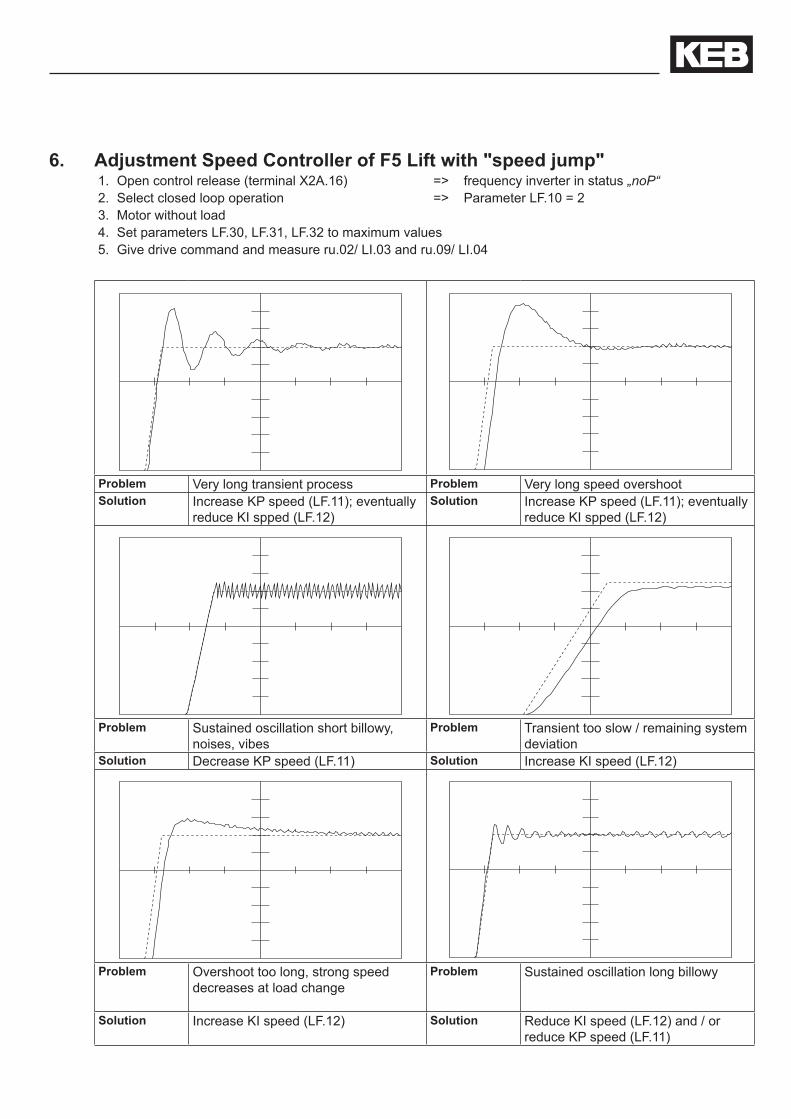
6. Adjustment Speed Controller of F5 Lift with "speed jump"1. Open control release (terminal X2A.16) => frequency inverter in status „noP“2. Select closed loop operation => Parameter LF.10 = 23. Motor without load4. Set parameters LF.30, LF.31, LF.32 to maximum values5. Give drive command and measure ru.02/ LI.03 and ru.09/ LI.04
Problem Very long transient process Problem Very long speed overshootSolution Increase KP speed (LF.11); eventually
reduce KI spped (LF.12) Solution Increase KP speed (LF.11); eventually
reduce KI spped (LF.12)
Problem Sustained oscillation short billowy, noises, vibes
Problem Transient too slow / remaining system deviation
Solution Decrease KP speed (LF.11) Solution Increase KI speed (LF.12)
Problem Overshoot too long, strong speed decreases at load change
Problem Sustained oscillation long billowy
Solution Increase KI speed (LF.12) Solution Reduce KI speed (LF.12) and / or reduce KP speed (LF.11)
KEB Antriebstechnik Austria GmbHRitzstraße 8 • A-4614 Marchtrenk
fon: +43 7243 53586-0 • fax: +43 7243 53586-21net: www.keb.at • mail: [email protected]
KEB AntriebstechnikHerenveld 2 • B-9500 Geraadsbergen
fon: +32 5443 7860 • fax: +32 5443 7898mail: [email protected]
KEB Power Transmission Technology (Shanghai) Co.,Ltd.No. 435 QianPu Road, Songjiang East Industrial Zone,
CHN-201611 Shanghai, P.R. Chinafon: +86 21 37746688 • fax: +86 21 37746600
net: www.keb.cn • mail: [email protected]
KEB Antriebstechnik Austria GmbHOrganizační složka
K. Weise 1675/5 • CZ-370 04 České Budějovicefon: +420 387 699 111 • fax: +420 387 699 119net: www.keb.cz • mail: [email protected]
KEB Antriebstechnik GmbHWildbacher Str. 5 • D–08289 Schneeberg
fon: +49 3772 67-0 • fax: +49 3772 67-281mail: [email protected]
KEB EspañaC/ Mitjer, Nave 8 - Pol. Ind. LA MASIA
E-08798 Sant Cugat Sesgarrigues (Barcelona)fon: +34 93 897 0268 • fax: +34 93 899 2035
mail: [email protected]
Société Française KEBZ.I. de la Croix St. Nicolas • 14, rue Gustave Eiffel
F-94510 LA QUEUE EN BRIEfon: +33 1 49620101 • fax: +33 1 45767495
net: www.keb.fr • mail: [email protected]
KEB (UK) Ltd.6 Chieftain Buisiness Park, Morris Close
Park Farm, Wellingborough GB-Northants, NN8 6 XFfon: +44 1933 402220 • fax: +44 1933 400724
net: www.keb-uk.co.uk • mail: [email protected]
KEB Italia S.r.l.Via Newton, 2 • I-20019 Settimo Milanese (Milano)
fon: +39 02 33535311 • fax: +39 02 33500790net: www.keb.it • mail: [email protected]
KEB Japan Ltd.15–16, 2–Chome, Takanawa Minato-ku
J–Tokyo 108-0074fon: +81 33 445-8515 • fax: +81 33 445-8215
mail: [email protected]
KEB Korea SeoulRoom 1709, 415 Missy 2000
725 Su Seo Dong, Gang Nam GuROK-135-757 Seoul/South Korea
fon: +82 2 6253 6771 • fax: +82 2 6253 6770mail: [email protected]
KEB RUS Ltd.Lesnaya Str. House 30, Dzerzhinsky (MO)
RUS-140091 Moscow regionfon: +7 495 550 8367 • fax: +7 495 632 0217
net: www.keb.ru • mail: [email protected]
KEB SverigeBox 265 (Bergavägen 19)
S-43093 Hälsöfon: +46 31 961520 • fax: +46 31 961124
mail: [email protected]
KEB America, Inc.5100 Valley Industrial Blvd. South
USA-Shakopee, MN 55379fon: +1 952 224-1400 • fax: +1 952 224-1499
net: www.kebamerica.com • mail: [email protected]
© KEBMat.No. 00F5LEB-K220
Rev. 1DDate 11/2010
More and newest addresses at http://www.keb.de
Karl E. Brinkmann GmbHFörsterweg 36-38 • D-32683 Barntrup
fon: +49 5263 401-0 • fax: +49 5263 401-116net: www.keb.de • mail: [email protected]
KEB worldwide…