libra ul-r pre-wired enclosure installation manual · libra ul-r pre-wired enclosure installation...
TRANSCRIPT

IGEA BTPHOBOS BTCOMPATIBLE WITH:COMPATIBLE WITH:
LIBRA UL-R PRE-WIRED ENCLOSURE
INSTALLATION MANUAL
ECOSOL BOOK 2 OF 2
VERSION 101116

SECURITY BOLTS. To be used on solar panel bracket. Once fixed and secured, makes the removal of the bolts virtually impossible. Great for theft prevention. Part no. N999475
T-BOX WIRELESS KEYLESS ENTRY KEYPAD. Self-contained, standalone access keypad. 10 channels, 100 codes capacity. Compatible with the ECOSOL built-in radio receiver. Part no. P121019
RB WIRELESS WALLMOUNT CONTROL STATION. Up to 4 systems can be controlled with this sleek 4 button station. For indoor or outdoor use. Part no. P121016
STAINLESS STEEL POST MOUNT BRACKET. For solar panel. Easy installation to post 2” to 4” in diameter. Part no. N999473
HIGH CAPACITY BATTERIES. 12V, 9 Ah. To replace or add to existing system. Up to 4 batteries can be installed in the enclosure. They must be added in pairs. Part no. KBAT12V9AH
SOLAR PANEL. 10 watts, 24v. Up to 3 can be installed to the system for increased charging capacity. Part no. N999471
ACCESSORIES2

PRODUCT PURCHASE AND INSTALLATIONThis product is intended to only be installed by a qualified professional technician. The warranty on the
equipment may be voided if not properly installed. Warranty claims should be directed to the company or entity that sold the equipment. Purchasing non-installed equipment may later hinder any warranty claim because of conflict between the equipment provider and the installer entity. It is highly recommended for the system to be supplied and installed by a single entity.
SOLAR POWERED SYSTEM CONSIDERATIONSThe ECOSOL solar powered system is intended for residential applications and light commercial gate
operation with limited cycles per day. While our system can operate over 300 cycles and/or provide over 2 weeks of standby time on fully charged batteries, it needs enough standby time to fully recharge the batteries or it will eventually run out of charge to operate the system. We highly recommend to keep the system as simple as possible and avoid adding accessories that draw current from the batteries. The ECOSOL interface board manages energy consumption and powers down all components, accessories and peripherals that are not required to operate while the gate is fully closed or after 5 minutes of inactivity. For optimum performance, we recommend the following setup:
●One or two actuators (Phobos BT or Igea BT) connected to the ECOSOL system.●Two sets of photo-beam obstruction sensors.●BFT radio transmitters and/or wireless keypads programmed to the ECOSOL's built-in low consumption receiver.●Automatic closing timer enabled.
Anytime, additional accessories are added, it is suggested to increase the systems charging capacity by adding a solar panel. See page 15 for further information.
EXISTING GATE CONDITIONAutomation should be installed on a gate which is moving freely. Any issue with the smooth opening or closing of a gate will not be corrected by adding automation.
READ BEFORE INSTALLING
SYSTEM RECOMMENDATIONS 3

ACCESSORIESSYSTEM RECOMMENDATIONSINSTALLATION CHECKLISTIMPORTANT SAFETY INFORMATIONUL325 INSTALLATION RECOMENDATIONSINSTALLATION SAFETYOPERATIONAL SAFETYTHE SYSTEMINSTALLING THE ENCLOSUREPOSITIONING THE SOLAR PANELMOUNTING THE SOLAR PANELWIRING THE SOLAR PANELADDING SOLAR PANELSINSTALLING THE BATTERIESMOTOR CONNECTIONSSAFETY DEVICESOPENING DEVICES CONTROL WIRING ECOSOL SETTINGS LIBRA UL-R PROGRAMMING MAIN MENU PARAMETERS SUB-MENU LOGIC SUB-MENU INITIAL PROGRAMMING COMMON OPTIONS RADIO TRANSMITTERS MAINTENACETROUBLESHOOTINGDISPLAY GLOSSARY
.................................................................................................. 02.......................................................................... 03
........................................................................... 05................................................................. 06
....................................................... 07.................................................................................... 08
..................................................................................... 09.................................................................................................... 10
.......................................................................... 11..................................................................... 12
........................................................................ 13.............................................................................. 14
.................................................................................. 15........................................................................... 16
................................................................................... 23............................................................................................. 18
.......................................................................................... 19........................................................................................... 20.......................................................................................... 21
............................................................................ 22..................................................................................................... 23
................................................................................. 24............................................................................................ 25
................................................................................... 26.......................................................................................... 27
.................................................................................... 28................................................................................................ 29
........................................................................................ 30
........................................................................................ 31
TABLE OF CONTENTS4

CAREFULLY READ ALL SAFETY INFORMATION. Pages 6 - 9
Install the gate operator(s) according to the installation manual (Book 1 of 2).
Determine the best location for your solar panel. Page 12
Secure ECOSOL enclosure to wall, column or post. Page 11.
Determine the orientation and inclination of the solar panel and install it. Pages 12 & 13.
Wire solar panel or panels to the ECOSOL system Pages 14 & 15.
Install batteries. Page 16.
Connect motor wires to the ECOSOL system. Page 23.
Connect obstruction sensing devices. Page 18.
Connect opening devices (if applicable). Page 19.
Connect other control devices (if applicable) Page 20.
Set the controller to SINGLE GATE OPERATION if needed. Page 26.
Perform the AUTOSET. Page 26.
Set other features if needed. Page 27.
Adjust parameters if needed. Page 24.
Program remote controls and/or wireless keypad(s). Page 28.
Test all safety devices and features.
INSTALLATION CHECKLIST 5

GATE AUTOMATION INSTALLATION SAFETYWhile the manufacturer has designed the system under strict safety standards, it is ultimately the installers
responsibility to follow and comply with national and local laws, codes and safety standards that apply to themechanical, electrical and operational aspects of the gate automation system. These include but are not limited to:safety standards established by entities like Underwriters Laboratory (UL), NFPA 70, or codes and laws stated bycorresponding state, county or municipality.
While it may not be compulsory, we highly recommend following UL 325 safety standards.
UL 325 VEHICULAR GATE AUTOMATION CLASSIFICATION
This system can be used in Class I, Class II and Class III applications.
• CLASS I – RESIDENTIAL VEHICULAR GATE OPERATOR - A vehicular gate operator (or system) intended foruse in a home of one-to four single family dwelling, or a garage or parking area associated therewith.
• CLASS II – COMMERCIAL/GENERAL ACCESS VEHICULAR GATE OPERATOR - A vehicular gate operator (orsystem) intended for use in a commercial location or building such as a multi-family housing unit (five ormore single family units), hotel, garages, retail store, or other building servicing the general public.
• CLASS III – INDUSTRIAL/LIMITED ACCESS VEHICULAR GATE OPERATOR - A vehicular gate operator (orsystem) intended for use in an industrial location or building such as a factory or loading dock area orother locations not intended to service the general public.
• CLASS IV – RESTRICTED ACCESS VEHICULAR GATE OPERATOR - A vehicular gate operator (or system)intended for use in a guarded industrial location or building such as an airport security area or otherrestricted access locations not servicing the general public, in which unauthorized access is preventedvia supervision by security personnel.
UL 325 ENTRAPMENT PROTECTION REQUIREMENTS
For all installation classes, it is required to properly adjust the inherent obstruction sensing system (AUTOSET, page26) and install warning signs on both sides of the gate, warning pedestrians of the dangers of the automated gatesystem. For Class I and Class II installations, it is required to add a non-contact device, such asa photoelectric eye OR a contact device such as a gate edge. For Class III installations it is required to add a non-contact device, such as a photoelectric eye, AND a contact device such as a gate edge OR an audio alarm such as asiren, horn or buzzer.
IMPORTANT SAFETY INFORMATION6

1. Install the gate operator only when:
a. The operator is appropriate for the construction and the usage class of the gate.
b. All openings of a horizontal slide gate are guarded or screened from the bottom of the gate to aminimum of 4' (1.2 m) above the ground to prevent a 2-1/4" (6 cm) diameter sphere from passingthrough the openings anywhere in the gate, and in that portion of the adjacent fence that the gatecovers in the open position.
c. All exposed pinch points are eliminated or guarded, and guarding is supplied for exposed rollers.
2. The operator is intended for installation only on gates used for vehicles. Pedestrians must be supplied witha separate access opening. The pedestrian access opening shall be designed to promote pedestrian usage.Locate the gate such that persons will not come in contact with the vehicular gate during the entire path oftravel of the vehicular gate.
3. The gate must be installed in a location so that enough clearance is supplied between the gate andadjacent structures when opening and closing to reduce the risk of entrapment. Swinging gates shall notopen into public access areas.
4. The gate must be properly installed and work freely in both directions prior to the installation of the gateoperator.
5. Controls intended for user activation must be located at least six feet (6') away from any moving part of thegate and where the user is prevented from reaching over, under, around or through the gate to operate thecontrols. Outdoor or easily accessible controls shall have a security feature to prevent unauthorized use.
6. The Stop and/or Reset (if provided separately) must be located in the line-of-sight of the gate. Activation ofthe reset control shall not cause the operator to start.
7. A minimum of two (2) WARNING SIGNS (supplied with the gate operator) shall be installed, one on each sideof the gate where easily visible.
8. For a gate operator utilizing a non-contact sensor:
a. Reference owner’s manual regarding placement of non-contact sensor for each type of application.
b. Care shall be exercised to reduce the risk of nuisance tripping, such as when a vehicle trips the sensorwhile the gate is still moving.
c. One or more non-contact sensors shall be located where the risk of entrapment or obstruction exists,such as the perimeter reachable by a moving gate or barrier.
9. For a gate operator utilizing a contact sensor such as an edge sensor:
a. One or more contact sensors shall be located where the risk of entrapment or obstruction exists, suchas at the leading edge, trailing edge and post mounted both inside and outside of a vehicular horizontalslide gate.
b. One or more contact sensors shall be located at the bottom edge of a vehicular vertical lift gate.
c. A hard wired contact sensor shall be located and its wiring arranged so the communication between thesensor and the gate operator is not subject to mechanical damage.
d. A wireless contact sensor such as the one that transmits radio frequency (RF) signals to the gateoperator for entrapment protection functions shall be located where the transmission of the signals arenot obstructed or impeded by building structures, natural landscaping or similar obstruction. A wirelesscontact sensor shall function under the intended end-use conditions.
e. One or more contact sensors shall be located on the inside and outside leading edge of a swing gate.Additionally, if the bottom edge of a swing gate is greater than 6" (152 mm) above the ground at anypoint in its arc of travel, one or more contact sensors shall be located on the bottom edge.
f. One or more contact sensors shall be located at the bottom edge of a vertical barrier (arm).
UL325 INSTALLATION RECOMMENDATIONS 7

GENERAL SAFETYWARNING! An incorrect installation or improper use of the product can cause damage to persons, animals orproperty. • Automation should be installed on a gate which is moving freely. Any issue with the smooth opening of closing of agate will not be corrected by adding automation.• Scrap packing materials (plastic, cardboard, polystyrene etc) according to the provisions set out by currentstandards. Keep nylon or polystyrene bags out of children’s reach.• Keep this instruction manual for future reference.• This product was exclusively designed and manufactured for the use specified in the present documentation. Anyother use not specified in this documentation could damage the product and be dangerous.• The Company declines all responsibility for any consequences resulting from improper use of the product, or usewhich is different from that expected and specified in the present documentation.• Do not install the product in explosive atmosphere. • The Company declines all responsibility for any consequences resulting from failure to observe Good TechnicalPractice when constructing closing structures (door, gates etc.), as well as from any deformation which might occurduring use.• Follow and comply with national and/or local electrical codes when performing any electrical installation. • Disconnect the electrical power supply before carrying out any work on the installation. Also disconnect any bufferbatteries, if fitted.• Fit all the safety devices (photocells, electric edges etc.) which are needed to protect the area from any dangercaused by squashing, conveying and shearing, according to and in compliance with the applicable directives andtechnical standards.• It is recommended to position at least one luminous signal indication device (blinker) where it can be easily seenfor additional safety• The Company declines all responsibility with respect to the automation safety and correct operation when othermanufacturer’s components are used.• Only use original parts for any maintenance or repair operation.• Do not modify the automation components, unless explicitly authorized In writing by the Company.• Instruct the product user about the control systems provided and the manual opening operation in case ofemergency.• Anything which is not expressly provided for in the present instructions, is not allowed.• Installation must be carried out using the safety devices and controls prescribed by the UL 325 Standard.
CHECKING INSTALLATIONBefore the automated device is finally put into operation, perform the following checks meticulously:• Make sure all components are fastened securely.• Check that all safety devices (photocells, pneumatic safety edge, etc.) are working properly.• Check the emergency operation control device.• Check opening and closing operations with the control devices applied.• Check the electronic logic for normal (or personalized) operation in the control panel.
ADJUSTING OPERATING FORCEWARNING: Operating force is adjusted with extreme precision by means of the control unit’s electronic control.Operation at the end of travel is adjusted electronically in the control panel. To provide good anti-crush safety, theoperating force must be slightly greater than that required to move the leaf both to close and to open it.
CONTROLThere are various options when it comes to the control system (manual, remote control, access control withmagnetic badge, etc.) depending on the installation’s needs and characteristics. See the relevant instructions forthe various control system options. People due to use the automated device must be instructed how to control anduse it.
INSTALLATION SAFETY8

The installer is responsible for communicating the following information to the end-user:This product has been designed and built solely for the purpose indicated herein. Uses not contemplated herein
might result in the product being damaged and could be a source of danger.The Firm disclaims all responsibility resulting from improper use or any use other than that for which the product
has been designed, as indicated herein, as well as for failure to apply Good Practice in the construction of entrysystems (doors, gates, etc.) and for deformation that could occur during use. If installed and used correctly, theautomated system will meet the required level of safety. Nonetheless, it is advisable to observe certain rulesof behavior so that accidental problems can be avoided:
• Keep adults, children and property out of range of the automated system, especially while it is operating.• Operate the system when the full path of the gate is within sight.• It is essential to frequently check that all safety devices are in good working condition.• This application is not meant for use by people (including children) with impaired mental, physical or
sensory capacities, or people who do not have suitable knowledge, unless they are supervised or have beeninstructed by people who are responsible for their safety.
• Children must be supervised to ensure they do not play with the system. Keep remote controls or othercontrol devices out of reach of children in order to avoid the automated system being operatedinadvertently.
• Check the system frequently, especially hinges, cables, springs or supports, to detect any loss of balanceand signs of wear or damage.
• When cleaning the outside or performing other maintenance work, always cut off mains power.• Keep the photocells’ optics and illuminating indicator devices clean. Check that no branches or shrubs
interfere with the safety devices (photocells).• Do not use the automated system if it is in need of repair. In the event of a malfunction, cut off the power,
activate the emergency release to allow access and call in qualified technical personnel (professionalinstaller).
• If the automated system requires work of any kind, employ the services of qualified personnel (professionalinstaller).
• Anything that is not explicitly provided for in these instructions is not allowed.• The operator’s proper operation can only be guaranteed if the information given herein is complied with.
The Firm shall not be answerable for damage caused by failure to comply with the installation rules andinstructions featured herein.
• Have the complete system checked including all safety devices by a qualified professional technician atleast once a year.
Descriptions and illustrations herein are not binding. While we will not alter the product’s essential features, theFirm reserves the right, at any time, to make those changes deemed necessary to improve the product from atechnical, design or commercial point of view, and will not be required to update this publication accordingly.
OPERATIONAL SAFETY 9

(2) 12V, 9 Ah batteries30% more capacity than standard 7 Ah batteries
TEST BUTTONTriggers the START input for the installer's and service technician's convenience.
ECOSOL INTERFACE BOARD● Regulates the power from the solar panel(s)● Monitors battery charge● Charges batteries● Manages power. Shuts down all components not needed when system is not in use● Processes starting commands. Powers up the system and relays signals once system is operational● Receives radio commands. Has a built-in low power consumption radio receiver with a 64 transmitters capacity, eliminating the need for external receivers
LIBRA UL-R CONTROLLER● Controls (2) Phobos BT or Igea BT operators.● Self learning torque settings.● Adjustable independent gate leaf delay
THREADED HOLESFor the installation of (2) Diablo Controls DSP-6LP or DSP-7LP
TERMINAL BLOCKSClearly labeled, easy access terminal block connections
THE SYSTEM10
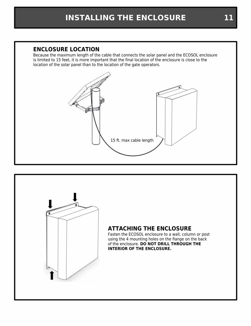
ATTACHING THE ENCLOSUREFasten the ECOSOL enclosure to a wall, column or post using the 4 mounting holes on the flange on the back of the enclosure. DO NOT DRILL THROUGH THE INTERIOR OF THE ENCLOSURE.
15 ft. max cable length
ENCLOSURE LOCATIONBecause the maximum length of the cable that connects the solar panel and the ECOSOL enclosure is limited to 15 feet, it is more important that the final location of the enclosure is close to the location of the solar panel than to the location of the gate operators.
INSTALLING THE ENCLOSURE 11
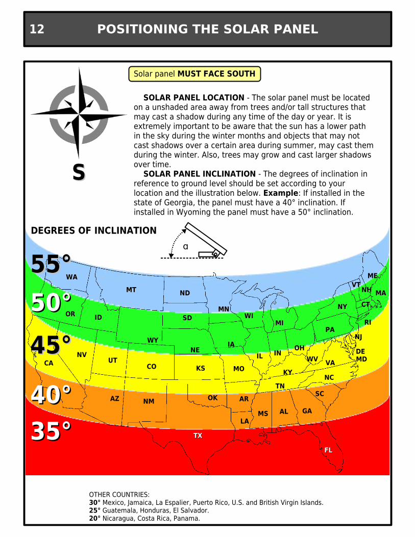
Solar panel MUST FACE SOUTH
SOLAR PANEL LOCATION - The solar panel must be located on a unshaded area away from trees and/or tall structures that may cast a shadow during any time of the day or year. It is extremely important to be aware that the sun has a lower path in the sky during the winter months and objects that may not cast shadows over a certain area during summer, may cast them during the winter. Also, trees may grow and cast larger shadows over time.
SOLAR PANEL INCLINATION - The degrees of inclination in reference to ground level should be set according to your location and the illustration below. Example: If installed in the state of Georgia, the panel must have a 40° inclination. If installed in Wyoming the panel must have a 50° inclination.
WAWA ME
OROR
CANV
IDID
UT
AZ
MTMT
WY
CO
NM
TXTX
OK
KS
NE
SDSD
NDND
MNMN
IA
MO
AR
WIWI
IL
LAMS AL GA
FLFL
SC
NCTN
KY
IN OH
MIMI
NYNY
PA
VAWV MDDE
NJ
MAMAVTVT
NHNH
CTCT
RI50°50°
40°40°
45°45°
35°35°
55°55°ɑ
OTHER COUNTRIES:30° Mexico, Jamaica, La Espalier, Puerto Rico, U.S. and British Virgin Islands.25° Guatemala, Honduras, El Salvador.20° Nicaragua, Costa Rica, Panama.
DEGREES OF INCLINATION
SS
POSITIONING THE SOLAR PANEL12

Secure “L” brackets to panel's frame
Attach mounting bracket to mounting surface. The hardware allows for wall mount or top mount installation
Mounting screws or anchors not included
Brackets can be attached at different heights on the panel to accommodate different installation
conditions
2” to 4” diameter post
Optional stainless steel adjustable post mount bracket is available. Part no. N999473
Attach the panel to the mounting bracket
Nylon lock nut
Bolt1
2
3
4
Pressure washer
3/4”
Flat washer
MOUNTING THE SOLAR PANEL 13

●Remove the 4 screws that hold the cover to the solar
panel terminal block.●Run the cable through (1) of
the connector fittings.●Connect the black wire to
the left (negative) terminal and the red wire to the right
(positive) terminal.
Connect the wires from the solar panel to the terminals labeled SOLAR PANEL – and SOLAR PANEL +
FROM SOLAR PANEL
15 ft. max cable length
CONNECT CABLE TO SOLAR PANEL
RUN THE CABLE TO THE ECOSOL ENCLOSURE
CONNECT CABLE TO TERMINAL STRIP
1
2
3
USE 16 AWG OR BETTER, STRANDED WIRES
WIRING THE SOLAR PANEL14

To Ecosol EnclosureTo next solar panel
Up to (3) 10 watts, 24v panels can be connected to the ECOSOL.
1st panel 2nd panel (optional) 3rd panel (optional)
ECOSOL
The solar panels must be connected in a parallel daisy chain where the black wires will only be connected to the negative terminal and the red wire will only be connected to the positive terminal on the solar panels.
KEEP THE CABLES AS SHORT AS POSSIBLE!!The wires should be stranded 16 AWG or better and no longer than 15ft.
(35W maximum total capacity)
ADDING SOLAR PANELS 15

When adding batteries...● Install (4) new batteries – Never mix used and new batteries● Make sure they have the same rating – Batteries may have the same physical size but have different characteristics (volts and ampere-hours)● Equalize the charge – all 4 batteries must be within 0.7 volts of each other. An easy way of accomplishing this is by fully charging them individually before installing.● Connect to ECOSOL - The primary pair of batteries must be connected to JP15(-) and JP16(+) while the secondary pair must be connected to JP23(+) and JP18(-).● Dipswitch 1 on the ECOSOL board MUST be turned on when secondary pair of batteries are connected
The ECOSOL /Libra is shipped with the batteries leads pre-installed. The negative (black) lead is not connected to prevent discharge before installation. To power up the system, connect the black lead to the negative battery terminal
The ECOSOL/Libra enclosure can hold up to (2) pairs (4 total) batteries for greater energy storage capacity. The battery brackets must be removed and the batteries must be rotated longways in order to fit them inside the enclosure.
PRIMARY PAIR
SECONDARY PAIR
WARNING
POWER UP
ADDING MORE BATTERIES
INSTALLING THE BATTERIES16

BFT PHOBOS BT AND IGEA BT GATE OPERATORS ONLY
When installing dual gate where the gates overlap (or has a lock mechanism), it is important that the motor that needs to open first is wired to MOTOR 2 terminals.
During the open cycle, MOTOR 2 starts first (MOTOR 1 has a delayed open start). During the close cycle, MOTOR 1 starts first (MOTOR 2 has a delayed close start).Both delays can be independently adjusted from 1 to 29 seconds. Please refer to page 2424 for further instructions.
When installing a single leaf gate operator, the motor leads must be wired to MOTOR 2 terminals and LIBRA controller must be configured to single gate operation. Please refer to page 26 for further instructions.
SINGLE GATE OPERATION
DUAL GATE OPERATION
MOTOR 2OPENS FIRSTCLOSES SECOND
MOTOR 1OPENS SECONDCLOSES FIRST
USE 16 AWG OR BETTER, STRANDED WIRES
USE 16 AWG OR BETTER, STRANDED WIRES
MOTOR CONNECTIONS 17

Photo-beam sensors should only be used as safety devices, NEVER as free exit devices.
NOTE: If more than one device needs to be wired to the Safety input, they must be wired in series
PHOTO BEAM AND SAFETY EDGE SENSORS
24VDCNORMALLY CLOSED
DURING NO OBSTRUCTION
MAGNETIC LOOP DETECTORS
24VDCNORMALLY CLOSED
DURING NO DETECTION
Loop detectors must ALWAYS BE POWERED to ensure proper detection.
Avoid the utilization of loop detectors. They decrease the standby time as well as the cycles per day. They also increase the battery charge time. If loop detectors are a must in your installation, look for low power consumption loop detectors such as Diablo Controls models DSP-6LP and DSP-7LP. ADDING AN ADDITIONAL SOLAR PANEL IS RECOMMENDED.
MULTIPLE SAFETY DEVICES
REMOVE FACTORYINSTALLED JUMPER
REMOVE FACTORYINSTALLED JUMPER
SAFETY DEVICES18

WIRELESS
24VDC
OPEN DEVICESNORMALLY OPEN CONTACTS
Avoid the utilization of external opening devices that require to be powered off the ECOSOL system. They decrease the standby time as well as the cycles per day capacity. They also increase the battery charge time. If a “free exit” device is a must in your installation, look for low power consumption loop detectors such as Diablo Controls models DSP-6LP and DSP-7LP or other low consumption devices. ADDING AN ADDITIONAL SOLAR PANEL IS RECOMMENDED.
The ECOSOL system has a built-in, low power consumption, radio receiver for BFT remote controls and wireless keypads. Any additional opening device powered off the system will decrease the system's battery performance
MITTO 22 button remote control
MITTO 44 button remote control
T-BOXBattery operated wireless keypad
HARD WIRED
SEE PAGE 28 FOR PROGRAMMING INSTRUCTIONS
OPENING DEVICES 19

NOTE: If more than one device needs to be wired to the STOP input, they must be wired in series
START / CLOSE INPUT
STOP / RESET BUTTON
3-BUTTON STATION (open, stop, close)
The Start/Close input can be used for a single push button operation to open, stop and close commands
The Stop button also resets the controller if two consecutive physical obstructions are detected. This is a NORMALLY CLOSED contact. The factory installed jumper must be removed for stop button to operate.
REMOVE FACTORYINSTALLED JUMPER
A 3-button station can be hard-wired using the START/CLOSE as close input. This input must be defined as CLOSE ONLY INPUT at the controller. See page 25 (START-CLOSE) for directions.
CONTROL WIRING20

LED 2
LED 4
LED 3
RADIO LEARN BUTTON
PROGRAMMING DIP-SWITCH BANK
DIPSWITCH PROGRAMMING●Switch 1 – Must be turned on ONLY when secondary pair of batteries is connected.●Switch 2 – Enables Quick Radio Programming●Switch 3 – Command relay delay (MUST BE TURNED ON)●Switch 4 – Command relay delay
LED LEGENDLED2 – Libra programming jumper (JP14) on indicatorLED3 – (1 flash/sec) Learning transmitter as START input.
(2 flashes/sec) Learning transmitter as OPEN input.(Steady) Hidden button learned.(3 flashes) Low battery (below 24V)
LED4 – Charging batteries
RADIO LEARN BUTTONPRESS ONCE – Initiates process of learning transmitters as START input. LED 3 will flash @ 1/sec.PRESS TWICE - Initiates process of learning transmitters as OPEN input. LED 3 will flash @ 2/sec.Refer to page 28 for further transmitter programming instructions.
DELETING THE MEMORYPRESS AND HOLD – Deletes all transmitters from memory. LED 3 will blink rapidly, then on steady.Once it turns off, release the RADIO LEARN BUTTON.
JP 14 jumper
ECOSOL SETTINGS 21

POWER UP THE CONTROLLERInstal the jumper provided on both pins labeled JP14 on the Ecosol interface board. As long as this jumper is in place the Libra UL-R will be powered for the programming process
JP14
Use the LCD display and the 3 buttons on the upper right corner of the Libra UL-R to navigate and manipulate the menu.
PRESS 2 TIMES TO ENTER THE MAIN PROGRAMMING MENU
USE THE AND BUTTONS TO SCROLL UP AND DOWN THE MENU
USE THE BUTTON AS “ENTER” TO SELECT A MENU CHOICE OR CONFIRM A PROGRAMMING ORDER
NAVIGATE THE PROGRAMMING MENU
PRESS AND AT THE SAME TIME TO EXIT PROGRAMMING
REMOVE JUMPER UPON PROGRAMMING COMPLETIONFailure to do so will result in rapid battery discharge
LIBRA UL-R PROGRAMMING22

USE THE BUTTON AS “ENTER” TO SELECT A MENU CHOICE OR CONFIRM A PROGRAMMING ORDER
PARAMETERS – Sub-menu where times and percentages are set (toque settings, run times, timer to close). See page 24.
LOGIC – Sub-menu where features are enabled or disabled. See page 25.
RADIO – Sub-menu where wireless devices (remote controls, wireless keypads, etc.) are programmed or deleted.
LANGUAGE – Menu area where the selection of the menu language is made
DEFAULT – By selecting this menu option, the control board restores all its factory settings and changes language to Italian. The RADIO area remains unchanged.
AUTOSET – By selecting this menu option, the actuators will automatically open and close at full torque and will self adjust its torque settings according to the gate weight. The operator's limit switches must be set and the gates must be in the fully closed position prior to performing the AUTOSET. Please refer to the operator's manual for proper limit switch setting procedure.
DISPLAY DESCRIPTION
DO NOT USE WITH ECOSOL
The main menu has 6 options. Of these 6, the first 3 are sub-menus (PARAMETERS, LOGIC, RADIO).Because the transmitters are programmed to the ECOSOL interface board, the RADIO sub-menu MUST NOT BE USED!
USE THE AND BUTTONS TO SCROLL UP AND DOWN THE MENU
PRESS AND AT THE SAME TIME TO EXIT PROGRAMMING
MAIN MENU 23

WHILE IN THE SUB-MENU
● TCA – Auto Close Timer. Range: 3-60 seconds. Default: 10
● M1 T – Motor 1 Torque. Range: 1-99%. Default: 50
● M2 T – Motor 2 Torque. Range: 1-99%. Default: 50
● M1 T SLOW – Motor 1 Slowdown Torque. Range: 1-99%. Default: 45
● M2 T SLOW – Motor 2 Slowdown Torque. Range: 1-99%. Default: 45
● OPEN DELAY TIME – Motor 1 open delay. Range: 1.0-10 seconds. Default: 1.0
● CLS DELAY TIME – Motor 2 close delay. Range: 1.0-10 seconds.Default: 1.0
● M1 FAST TIME – Motor 1 full speed run time. Range: 1.0-30 seconds.Default: 15.0
● M2 FAST TIME – Motor 2 full speed run time. Range: 1.0-30 seconds.Default: 15.0
● SLOW SPEED – Slowdown speed. Range: 0=Disabled, 1=50%, 2=33%, 3=25%Default: 0
● ZONE – NOT USED
DISPLAY DESCRIPTION
USE THE AND INCREASE OR DECREASE THE PARAMETER VALUE
USE THE BUTTON AS “ENTER” TO CONFIRM THE DESIRED VALUE
PRESS AND AT THE SAME TIME TO RETURN TO THE MAIN MENU
NO EFFECT WITH ECOSOL
NO EFFECT WITH ECOSOL
NO EFFECT WITH ECOSOL
NO EFFECT WITH ECOSOL
NO EFFECT WITH ECOSOL
Navigation of the sub-menu is the same as the main menu. Once a sub-menu selection has been made:
PARAMETER OPTIONS
PARAMETERS SUB-MENU24

WHILE IN THE SUB-MENU
DISPLAY DESCRIPTION
USE TO TURN ON AND TO TURN OFF THE SELECTED FEATURE.
USE THE BUTTON AS “ENTER” TO CONFIRM THE DESIRED VALUE
PRESS AND AT THE SAME TIME TO RETURN TO THE MAIN MENU
Navigation of the sub-menu is the same as the main menu. Once a sub-menu selection has been made:
LOGIC OPTIONS
● TCA – Auto Close Timer. Default: OFF
● 3 STEP – Instant reverse. Gate instantly reverses on START activation during the CLOSE cycle as opposed to stopping and requiring a 2nd START input for re-opening. Default: OFF
● IBL OPEN – Ignore START input during OPEN cycle . Default: OFF
● FAST CLS – Gate closes immediately after SAFETY input is cleared. Default: OFF
● PHOTOC OPEN – Ignore SAFETY input during OPEN cycle. If OFF, gate stops on SAFETY input activation during the OPEN cycle. Default: OFF
● TEST PHOT – Enables the SAFETY input supervision circuit. Default: OFF
● 1 MOT ON – Single gate operation. Ignores MOTOR 1. Default: OFF
● BLOC PERSIST – Operator pushes for 0.5 seconds after CLOSE limit is reached. PHYSICAL GATE STOP IS REQUIRED. Default: OFF
● START-CLOSE – Converts START/CLOSE input into CLOSE ONLY input.Default: OFF
● FIXED CODE – Disables the receiver's rolling code feature. Default: OFF
● RADIO PROG – Enables Quick Remote Programming. Default: ON
NO EFFECT WITH ECOSOL
NO EFFECT WITH ECOSOL
● MASTER – NOT USED. Default: OFF
DO NOT USE WITH ECOSOL
LOGIC SUB-MENU 25

SINGLE MOTOR OPERATION
From the main programming menu, scroll to LOGIC and press OK
Scroll down to 1 MOT ON and press OK
Press the button to switch to ON and press OK
Use the and buttons to navigate up or down the LOGIC Sub-menu
Press the and buttons AT THE SAME TIME to return to the MAIN MENU
THE PROGRAMMING MAIN MENU
Press the OK button twice to enter the programming MAIN MENU
Use the and buttons to navigate up or down the MAIN MENU
Press the and buttons AT THE SAME TIME to exit programming
AUTOMATIC TORQUE ADJUSTMENT (AUTOSET)
WARNING – Gate path must be free of all traffic and obstructions. The system will
automatically open and close the gate at full torque while performing the self-learning
adjustment. Failure to do so can result in property damage and/or bodly injury including
death.
Gate must be fully closed and operators must have the CLOSE limit triggered before starting
From the main programming menu, scroll to AUTOSET and press OK
Upon completion of the close cycle, the screen should display OK. Press OK to finalize the
process.
If KO is diplayed, check for unsual physical gate hardware resistance or incorrect installation
geometry and try again.
Use the and buttons to navigate up or down the MAIN MENU
Press the and buttons AT THE SAME TIME to exit programming
INITIAL PROGRAMMING26
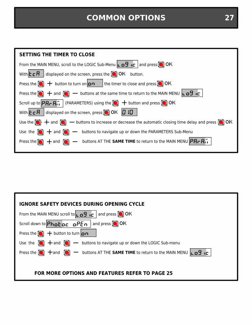
SETTING THE TIMER TO CLOSE
From the MAIN MENU, scroll to the LOGIC Sub-Menu and press OK
With TCA displayed on the screen, press the OK button.
Press the + button to turn on the timer to close and press OK.
Press the + and – buttons at the same time to return to the MAIN MENU
Scroll up to (PARAMETERS) using the + button and press OK.
With TCA displayed on the screen, press the OK .
Use the + and – buttons to increase or decrease the automatic closing time delay and press
Use the and buttons to navigate up or down the PARAMETERS Sub-Menu
Press the and buttons AT THE SAME TIME to return to the MAIN MENU
IGNORE SAFETY DEVICES DURING OPENING CYCLE
From the MAIN MENU scroll to LOGIC and press OK
Scroll down to PHOTOC OPEN and press OK
Press the + button to turn ON
Use the and buttons to navigate up or down the LOGIC Sub-menu
Press the and buttons AT THE SAME TIME to return to the MAIN MENU
FOR MORE OPTIONS AND FEATURES REFER TO PAGE 25
COMMON OPTIONS 27

1
STEADY BLINKING
PRESS AND HOLD THE ON BUTTON UNTIL THE RED LED TURNS ON STEADY
2 ENTER THE 4 DIGIT CODE FOR CHANNEL 1 (DEFAULT=1111) 3 PRESS THE ON BUTTON. RED
LED MUST BE BLINKING
4 PRESS THE RADIO LEARN BUTTON ON THE ECOSOL, ONCE TO ENABLE THE KEYPAD TO OPEN AND CLOSE THE GATE -OR- TWICE TO ENABLE THE KEYPAD TO ONLY OPEN THE GATE
5 PRESS THE ON BUTTON. WAIT 10 SECONDS BEFORE TESTING THE KEYPAD. REFER TO T-BOX MANUAL FOR INSTRUCTIONS ON HOW TO CHANGE DEFAULT CODE
BLINKS AND
TURNS OFF
PROGRAMMING THE T-BOX (Not included)
PROGRAMMING THE MITTO
BACK OF TRANSMITTERPhysical hidden button
FRONT OF TRANSMITTER
Virtual hidden buttonBoth buttons at the same time
OR
1 PRESS THE RADIO LEARN BUTTON ON THE ECOSOL, ONCE TO ENABLE THE REMOTE TO OPEN AND CLOSE THE GATE -OR- TWICE TO ENABLE THE REMOTE TO ONLY OPEN THE GATE
2 PRESS AND HOLD THE HIDDEN BUTTON UNTIL THE RED LED TURNS ON SOLID
3 PRESS THE BUTTON WHICH YOU WOULD LIKE THE GATE TO OPERATE WITH. FOR ADDITIONAL MITTOS, GO TO STEP 2. WAIT 10 SECONDS AFTER LAST TRANSMITTER LEARNED TO TEST.
RADIO TRANSMITTERS28

SOLAR PANEL
The cells in a solar panel are dependent one on another. If one cell is shaded, it affects the output of the rest of the cells in the panel. Depending on which cell is obstructed, the total output of the panel can decrease by over 75%. It is very important to keep the surface of the solar panel clean and free of any obstruction.
Because the sun has a lower path in the sky, and the days are shorter during the winter months, our suggested panel inclination is optimized for this time of the year. Verify that the solar panel has not been moved and that its inclination and orientation is correct. Refer to page 12 for more information.
SURROUNDING AREA
Inspect the surrounding area at least every winter. Objects can cast a longer shadow during the winter than during the summer. Also, trees and foliage can grow and cast shadow in areas previously clear of any shadows.
BATTERY
The batteries included with your ECOSOL system are sealed maintenance free batteries. However, depending on usage and temperature conditions your batteries will require periodic replacement. Batteries may last up to 5 years under optimal conditions. Please call your qualified service technician for the replacement of them. See page 16 for more information on battery installation.
GATE OPERATOR
Gate operator maintenance should be performed by a qualified service technician. Please refer to the operator's manual (Book 1) for more information.
GATE HARDWARE
Disengage operator(s) using its manual release. Open and close the gate manually and look for unusual resistance. The gate should not drag on the floor at any point of the travel and it should move freely without much effort. If any anomaly is found, do not re-engage the operator and call your qualified service technician for repairs.
MAINTENANCE 29

System does not turn on
System turns on, but gate does not move.
Gate stops and reverses after it starts to move. AMP is displayed on board.
Gate stops during the opening cycle.
After days of operation, the system stopped working.
1. Press the test button. System should power up and after a short delay gate should start moving.
2. Make sure that both battery leads and the jumper between the batteries are connected, and the polarity is correct. Page 16.
3. Inspect the ECOSOL interface board main fuse for continuity.
4. Completely disconnect the batteries and measure voltage. Each battery should at least measure 8 volts for the system to power up.
1. Verify that dip-switch 3 is turned on at the ECOSOL interface board. Page 21.
2. Inspect external devices such as photo-beam sensors for obstruction detection or false activation.
3. Press the reset button and retry. If gates move after reset,inspect the gate hardware by moving the gates manually and checking for unusual resistance.
4. Inspect motor lead connections both at the enclosure and the operator. Page 17.
1. Check for physical obstructions on the gate path.
2. Inspect the gate hardware by moving the gates manually and checking for unusual resistance.
3. Reset torque settings by performing an AUTOSET. Page 26.
1. Make sure that the safety devices are not being triggered. To ignore external safety devices during the opening cycle, enable the PHOTOC OPEN option under the LOGIC sub-menu. Page 27.
2. Inspect the gate hardware by moving the gates manually and checking for unusual resistance.
3. Reset torque settings by performing an AUTOSET. Page 26.
1. Make sure that the jumper on JP14 is not closed (over both pins). Page 22.
2. Check wire connections between solar panel and ECOSOL. Page 14.
3. Make sure that the solar panel is not shaded at anytime during the day.
4. Verify angle and orientation of solar panel. Page 12.
5. Add an additional solar panel to increase the system's recharging capacity. Page 15.
6. Add an additional pair of batteries to increase the energy storage capacity. Page 16.
TROUBLESHOOTING30

1 MOT ON - See page 25
3 STEP - See page 25
ADD START- DOESN'T APPLY TO ECOSOL
AMP - Indicates motor overload.
AUTOSET - See page 23
BLOC PERSIST - See page 25
CLS- CLOSE input triggered
CLS DELAY TIME - See page 24
COD RX - DOESN'T APPLY TO ECOSOL
DEFAULT - See page 23
DESIRED BUTTON - DOESN'T APPLY TO ECOSOL
END - Indicates END OF PROGRAMMING
ENG - ENGLISH language
ERASE 64 - DOESN'T APPLY TO ECOSOL
ESP- SPANISH language
FAST CLS - See page 25
FIXED CODE - See page 25
FLT - DOESN'T APPLY TO ECOSOL
FRA - FRENCH language
HIDDEN BUTTON - DOESN'T APPLY TO ECOSOL
IBL OPEN - See page 25
ITA - ITALIAN language
KO - Indicates programming error
LANGUAGE - See page 23
LOGIC - See page 23
M1 - Refers to MOTOR 1
M1 FAST TIME - See page 24
M1 T - See page 24
M1 T SLOW - See page 24
M2 - Refers to MOTOR 2
M2 FAST TIME - See page 24
M2 T - See page 24
M2 T SLOW - See page 24
MASTER - See page 25
OK - Indicates programming accepted
OPEN - OPEN input triggered
OPEN DELAY TIME - See page 24
PARAM - See page 23
PHOT - SAFETY input triggered
PHOTOC OPEN - See page 25
RADIO - See page 23
RADIO PROG - See page 25
RELEASE - DOES NOT APPLY TO ECOSOL
SLOW SPEED - See page 24
START-CLOSE - See page 25
STOP - STOP input triggered
STRT - START input triggered
TCA - Refers to TIMER TO CLOSE. See pages 24 & 25.
TEST PHOT - See page 25
ZONE - See page 24
DISPLAY GLOSSARY 31

BFT USA6100 Broken Sound Pkwy N.W.Suite 14Boca Raton FL 33487, U.S.A.Toll Free (U.S. Only): 877-995-8155Main Office: 561-995-8155Fax: 561-995-8160Email: [email protected]
WELCOME TO WORLD OF TRUSTBFT is a world leading manufacturer of innovative and highly reliable
electromechanical and hydraulic gate automation systems. We pride ourselves in providing outstanding customer service.
BFT is a global company in business since 1980 with subsidiaries in 15 countries worldwide. It is owned since 2004 by Somfy, the world leader in automation for window shades and shutters.
BFT US Inc, with its offices in Boca Raton, Florida offers, sales, logistics, technical support and customer service throughout USA, Canada and the Caribbean Islands
INSTALLED BY:
PHONE:INSTALLATION DATE:
INVOICE NUMBER:
TECH SUPPORT U.S. TOLL FREE: 877-995-8155 / INT'L: +1-561-995-8155