li chassis g - - boardindeks · pdf file · 2015-04-30chassis en g li sh index...
TRANSCRIPT


1
Chassis
EN
GLI
SH
Index
INTRODUCTION
MANUAL UPDATES
SYMBOLOGY USED IN THE MANUAL
ABBREVIATIONS USED IN THE MANUAL
GENERAL WORK RULES
RECOMMENDATIONS
GETTING TO KNOW THE MOTORBIKE
MAINTENANCE OPERATIONS
TECHNICAL SPECIFICATIONS
UNPACKING
APPARANCE
DATA FOR IDENTIFICATION
ANTI-TAMPERING LABEL
IDENTIFYING THE MAIN ELEMENTS
CONTROLS
KEYS
STEERING LOCK
SIDE STAND
INSTRUMENT PANEL
TYRES
CHECKING TYRE PRESSURES
FUEL TANK
COOLANT
REPLACING COOLANT
ENGINE OIL
TRANSMISSION OIL
BRAKE FLUID
ADJUSTING THE MINIMUM REV SETTING
ADJUSTING TRANSMISION CHAIN TENSION
6
7
8
9
10
15
15
18
18
18
18
19
20
20
20
20
21
22
22
22
23
23
24
24
25
25
26

EN
GLIS
H
Chassis
2
Index
DISASSEMBLY
1. REAR VIEW MIRRORS
2. FRONT HEADLIGHT HOLDER
3. FRONT SIDE COVERS
4. SEAT
5. NUMBER PLATE HOLDER
6. REAR COVER
7. FRONT MUDGUARD
8. FUEL TANK
9. FUEL TANK PROTECTOR
10. HANDLEBARS
11. STEERING
12. CLUTCH LEVER
13. FRONT BRAKE CYLINDER
14. FRONT HEADLIGHT
15. FRONT INDICATOR LIGHTS
16. REAR LIGHT
17. REAR INDICATOR LIGHTS
18. INSTRUMENT PANEL
19. TURN INDICATOR REGULATOR
20. CONTACT RELAY
21. CONTROL UNIT (CDI)
22. BATTERY
23. OIL SENSOR
24. OIL TANK
25. AIR FILTER
26. FUEL TRANSMISSION/OIL MIXER
27. “AIS” SYSTEM
28. EXHAUST
29. SILENCER
30. RADIATOR
31. CARBURETTOR
32. GEAR CHANGE LEVER
33. REAR BRAKE LEVER
34. SIDE STAND
28
28
29
29
30
30
30
31
31
32
32
33
33
34
34
35
35
36
36
37
37
38
38
38
39
39
39
40
40
41
41
42
42
43

3
Chassis
EN
GLI
SH
Index
35. REAR BRAKE CYLINDER
36. REAR BRAKE CALLIPER
37. ENGINE
38. REAR WHEEL
39. CHAIN PROTECTOR
40. DRIVE CHAIN
41. SHOCK ABSORBER
42. SWING ARM
43. FRONT WHEEL
44. FRONT BRAKE CALLIPER
45. FRONT BRAKE DISK
46. SPEED SENSOR
47. FRONT FOOTRESTS
48. REAR FOOTRESTS BRACKETW
48. TIGHTENING TORQUES
43
43
44
45
45
45
46
46
47
47
47
48
48
48
49

Introduction

5
EN
GLI
SH
IntroductionIntroduction
EN
GLIS
H
IntroductionChassis
6
This workshop manual contains the main electromechanical checks, as well as the essential general checks and the fitting of components supplied separately, designed to prepare the factory-new mo-ped for delivery.
It is very important to adhere strictly to the instructions set out in the manual. Interventions carried out superficially, or worse still, omitted entirely, may result in personal injury to the user, damage to the machine, etc., or may simply result in disagreeable complaints.
N.B.: Rieju, S.A. reserves the right to make changes at any time, without prior notification.For any enquiry, or for further complimentary information, please call the Rieju S.A. After-sales Service.
MANUAL UPDATES
Updates will be sent within a reasonable period of time. Each new CD-Rom will update previous information.
The contents list will be updated if the modifications and/or variations in the pages affect the ability to consult the manual.
IMPORTANT! This series of workshop manuals should be considered as work instruments in the-mselves and can only maintain their “value” over time if they are kept constantly up to date.

Introduction
7
Chassis
EN
GLI
SH
SYMBOLOGY USED IN THE MANUAL
CAUTION! Recommendations and precautions regarding rider safety and mo-tor vehicle integrity.
WARNING!Situations entailing the risk of personal injury to maintenance or repair mecha-nics, other workshop personnel or third parties, or damage to environment, vehicle or equipment.
FIRE HAZARDIndicates operations which may constitute a fire hazard.
RISK OF EXPLOSIONIndicates operations which may constitute a risk of explosion.
TOXIC Indicates a possibility of intoxication or inflammation of the upper respiratory tract.
MECHANICAL MAINTENANCEOperations to be performed only by an expert mechanic.
ELECTRICAL MAINTENANCEOperations be performed only by an expert electrical / electronic technician.
NO!Operations to be absolutely avoided.
SERVICE MANUALIndicates information which may be obtained by referring to said manual.
SPARE PARTS CATALOGUEIndicates information which may be obtained by referring to said catalogue.
TOXICTOXICTOXIC
EN
GLIS
H
IntroductionChassis
8
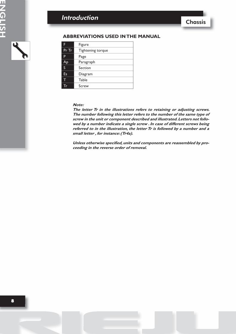
Note:The letter Tr in the illustrations refers to retaining or adjusting screws. The number following this letter refers to the number of the same type of screw in the unit or component described and illustrated. Letters not follo-wed by a number indicate a single screw . In case of different screws being referred to in the illustration, the letter Tr is followed by a number and a small letter , for instance: (Tr4a).
Unless otherwise specified, units and components are reassembled by pro-ceeding in the reverse order of removal.
F
Pr Tr
PAp
S
Es
T
Tr
Figure
Tightening torque
PageParagraph
Section
Diagram
Table
Screw
ABBREVIATIONS USED IN THE MANUAL

Introduction
9
Chassis
EN
GLI
SH
GENERAL WORK RULES
ADVICE:
F-1
•
•
•
•
•
•
•
•
Only use quality tools and equipment.
Only use equipment conforming to EU Directives for lifting the vehicle.
During operations, always keep tools and equipment at hand, possibly laying them out according to the sequence in which they are to be used. Absolutely avoid putting them on the vehicle itself, out-of-sight or in poorly accessible places.
Always keep the work area clean and tidy.
When tightening screws or nuts, start with the larger diameter or inner fasteners, and tighten them in progressive “pulls” in accordance to a “criss-cross” pattern.
Preferably use open-end box wrenches by “pulling” and not “pushing”.
Adjustable wrenches (F-1) should only be used in case of emergency, i.e. when a properly sized wrench is not available. They should preferably not be used as the movable jaw tends to open thus risking damaging or not properly tightening the bolt to the correct torque. In any case, when using an adjustable wrench, take care to proceed as shown in Figure 1.
Except for occasional customers, always make out and deliver to the customer a work sheet specifying the operations performed, with notes as to any future checks eventually required.
• The advice, recommendations and warnings given hereafter are aimed at ensuring maximum work safety as well as at considerably reducing the risk of accidents, personal injury, equipment damage and idle times. They should therefore be strictly adhered to.

EN
GLIS
H
IntroductionChassis
10
Before carrying out any operation on the vehicle, wait for all parts to cool down.
For operations requiring two mechanics, make sure that the various steps to be perfor-med by each of them are clearly defined and coordinated beforehand.
Make sure that each component has been properly fitted before proceeding with the next one.
Lubricate all parts (where applicable) before reinstalling them.
Gaskets, O-rings, circlips and split pins must be replaced at every refitting.
The torque settings specified in the manuals refer to the “final torque”, which must be attained progressively by steps.
Loosen and tighten aluminium alloy parts (covers) only after the engine has fully cooled down.
Only use screwdrivers with sizes suitable to the screws to be loosened or tightened.
Work in a comfortable position and ensure that the vehicle is stable.
Never use a screwdriver as a lever or chisel.
Never use pincers to loosen or tighten screws or nuts because, in addition to not providing a sufficient clamping force, they may also damage the screw head or nut hexagon.
Never tap the wrench with a hammer or other similar tools to loosen or tig-hten screws and nuts (F. 2).
Never attempt to increase the lever arm by fitting a tube into the wrench (F-3).
F-2 F-3
•
•
•
•
•
•
•
•
•
•
•
•
•
RECOMMENDATIONS

Introduction
11
Chassis
EN
GLI
SH
Never use open flames for any reason.
Never leave open containers or containers not suitable for holding fuel in passageways, close to heat sources, etc
Never use petrol to clean the vehicle or the floor of the workshop. Always use low flash point solvents to clean the vehicle components.
Never suck from or blow into the fuel pipe.
When welding, make sure that there are no flammable liquids in the vicinity. Always re-move the tank, even if completely empty, and disconnect the negative cable (-) from the battery.
Never leave the engine running in closed or poorly ventilated areas.
Before any servicing, make sure that the motorbike is perfectly stable.The front wheel should preferably be anchored to the equipment (A/F-4) integral with the lifting board.
F-4


13
EN
GLI
SH
Getting to know the motorbikeGetting to know the motorbike

EN
GLIS
H
Rieju chassisChassis
14
Rieju chassis
15
Chassis
EN
GLI
SH
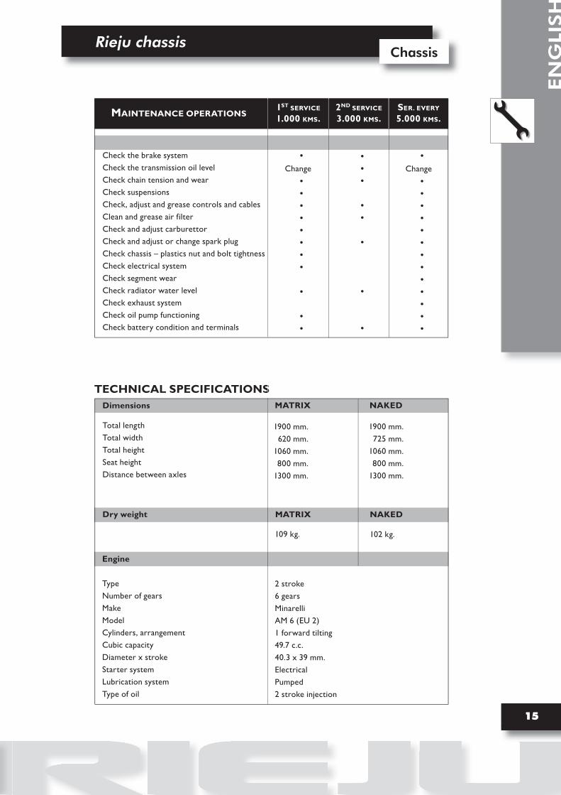
TECHNICAL SPECIFICATIONS
1ST SERVICE
1.000 KMS.2ND SERVICE
3.000 KMS.MAINTENANCE OPERATIONSSER. EVERY
5.000 KMS.
Check the brake systemCheck the transmission oil levelCheck chain tension and wearCheck suspensionsCheck, adjust and grease controls and cablesClean and grease air filterCheck and adjust carburettorCheck and adjust or change spark plugCheck chassis – plastics nut and bolt tightnessCheck electrical systemCheck segment wearCheck radiator water levelCheck exhaust systemCheck oil pump functioningCheck battery condition and terminals
·Change
···········
······
·
·
Dimensions
Total lengthTotal widthTotal heightSeat height Distance between axles
1900 mm.620 mm.
1060 mm.800 mm.
1300 mm.
Dry weight
109 kg.
Engine
TypeNumber of gearsMakeModelCylinders, arrangementCubic capacityDiameter x strokeStarter systemLubrication systemType of oil
2 stroke6 gearsMinarelliAM 6 (EU 2)1 forward tilting49.7 c.c.40.3 x 39 mm.ElectricalPumped2 stroke injection
·Change
·············
MATRIX NAKED
1900 mm.725 mm.
1060 mm.800 mm.
1300 mm.
MATRIX NAKED
102 kg.

EN
GLIS
H
Rieju chassisChassis
16
Transmission oil
TypeQuantity
SAE 10W 40820 c.c.
Air filter
Wet-type sponge rubber
Fuel
TypeTank capacity
95 octane lead-free petrol10 L.
Carburettor
Dellorto PHBN 16 HS
Spark plug
TypeElectrode gap
NGK BR 9 ES0,6 - 0,7 mm.
Clutch type
Multi-disk in oil bath
Primary transmission
Clutch crown wheelDrive pinionTransmission ratio
Z = 71Z = 201: 3,55
Secondary transmission
Engine output pinionDrag plateTransmission ratioChain
Z = 11Z = 471: 4,27420 SR x 126 links
Speed1ª2ª3ª4ª5ª6ª
Primary shaftZ = 12Z = 16Z = 19Z = 22Z = 24Z = 25
Secondary shaftZ = 36Z = 33Z = 29Z = 27Z = 25Z = 24
Gear ratio1: 3,001: 2,061: 1,531: 1,231: 1,041: 0,96
Output ratio1: 44,401: 31,201: 23,141: 18,601: 15,801: 14,56
GEARCHANGE
Rieju chassis
17
Chassis
EN
GLI
SH
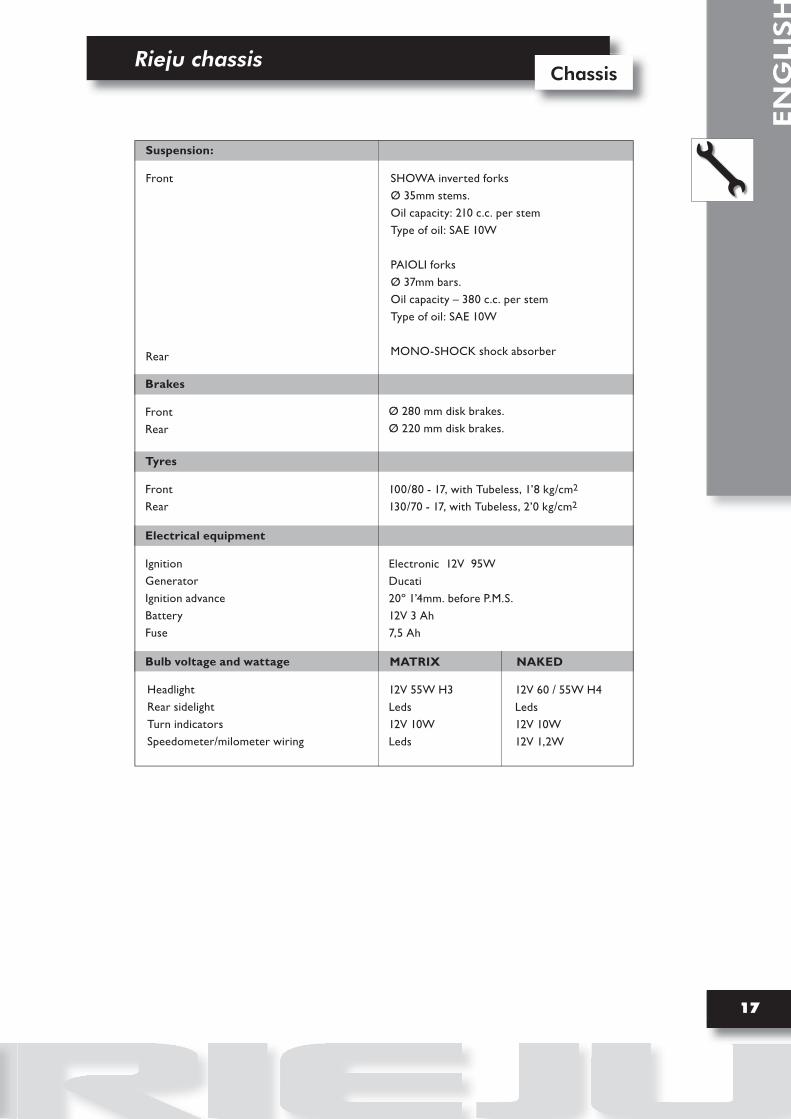
Suspension:
Front
Rear
SHOWA inverted forksØ 35mm stems. Oil capacity: 210 c.c. per stemType of oil: SAE 10W
PAIOLI forksØ 37mm bars. Oil capacity – 380 c.c. per stemType of oil: SAE 10W
MONO-SHOCK shock absorber
Brakes
FrontRear
Ø 280 mm disk brakes.Ø 220 mm disk brakes.
Tyres
FrontRear
100/80 - 17, with Tubeless, 1’8 kg/cm2
130/70 - 17, with Tubeless, 2’0 kg/cm2
Electrical equipment
IgnitionGeneratorIgnition advanceBattery Fuse
Electronic 12V 95WDucati20º 1’4mm. before P.M.S.12V 3 Ah7,5 Ah
Bulb voltage and wattage
Headlight Rear sidelight Turn indicators Speedometer/milometer wiring
12V 55W H3Leds12V 10WLeds
MATRIX NAKED
12V 60 / 55W H4Leds12V 10W12V 1,2W

EN
GLIS
H
Rieju chassisChassis
18
UNPACKING
Unpack the moped by following the instructions set out on the packing itself; the latter being then disposed of in accordance with existing regulations.
APPARANCE
Check visually that all the plastic material components are correctly fitted and that the machine has no visible scratches, marks, etc.
DATA FOR IDENTIFICATION
F-2
B
F-3
B
B
ANTI-TAMPERING LABEL
Contains the machine identification details (B/F-3) envisaged by Directive 97/24/CE.It is essential to indicate the machine identifica-tion details when ordering spare parts.This label must not be substituted or modified in any way.
It is located on the right hand side of the swin-ging arm.
•
•
•
•Machine identification numberThe machine identification number (B/F-2) is stamped onto the steering arm. This identifi-cation number is used to identify the moped.
F-1
A
Engine identification numberData for identifying the engine (A/F-1) can be seen on the left hand crankcase.
Rieju chassis
19
Chassis
EN
GLI
SH
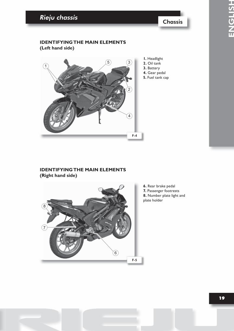
IDENTIFYING THE MAIN ELEMENTS(Left hand side)
1. Headlight2. Oil tank3. Battery 4. Gear pedal5. Fuel tank cap
IDENTIFYING THE MAIN ELEMENTS(Right hand side)
6. Rear brake pedal7. Passenger footrests8. Number plate light and plate holder
2
4
3
8
5
6
7
F-4
F-5
1

EN
GLIS
H
Rieju chassisChassis
20
CONTROLSControls/instruments
1. Main switch2. Clutch lever3. Turn signal switch4. Instrument panel5. Manual starter lever6. Front brake cylinder7. Front brake lever8. Throttle grip 9. Horn button10. Dipswitch
1
4
7
6
2
8
9
35
KEYS• The machine is supplied with two keys with a number code that enables: - The starter switch to be activated. - The steering to be locked.
STEERING LOCKActivation: With the handlebars turned to the left, insert the key fully and turn it to the left.• Deactivation: Turn the key to the right.
SIDE STAND• Check that the side stand is properly fitted and moves correctly. It is also recommended that the retaining system, consisting of traction springs, be regularly checked.
10
F-6
F-7

Rieju chassis
21
Chassis
EN
GLI
SH
INSTRUMENT PANEL
5
3
4
1
2
F-8
1-
2-
3-
4-
5-
6-
Turn indicator warning lightThis warning light flashes when the turn indicator switch is moved to the left or to the right.
Coolant temperature warning lightThis warning light comes on when the coolant temperature is too high. When the war-ning light comes on, stop the engine immediately.
Neutral position “N” warning lightThis warning light comes on when the transmission is in neutral position.
Oil level warning lightThis warning light comes on when the oil level is low.
Main beam warning lightThis indicator lights up when the main headlight beam is in use.
Fuel level warning lightThis warning light comes on when the petrol level is low.
6
5
3
1
F-9
6
NAKED version.
MATRIX RS2 version.

EN
GLIS
H
Rieju chassisChassis
22
TYRES
Dimensions100/80 - 17, with Tubeless, 1’8 kg/cm2
130/70 - 17, with Tubeless, 2’0 kg/cm2
CHECKING TYRE PRESSURES Tyre pressures must be checked and adjusted when the tyres are cold.
FUEL TANK
Lift the cover (A/F-11), open the cap using the key, and refill the tank, taking care not to exceed the limit. If petrol splashes are to be seen on the moped after refilling, clean these off immediately.Use normal lead-free petrol with a RESEARCH 95 octane number.
Fuel tank capacity: Total: 10 L.
FRONT
REAR
1,8 kg / cm2
2,0 kg / cm2
FRONT
REAR
F-11
bar
F-10
ADANGER OF FIREOperations that could start a fire.
DANGER OF EXPLOSION Operations that could set off an explosion.
Wheel
Rieju chassis
23
Chassis
EN
GLI
SH
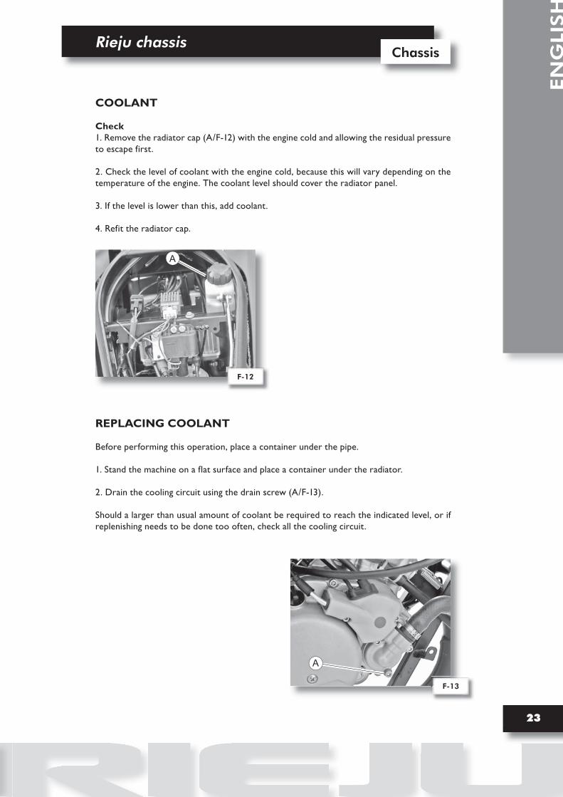
COOLANT
Check1. Remove the radiator cap (A/F-12) with the engine cold and allowing the residual pressure to escape first.
2. Check the level of coolant with the engine cold, because this will vary depending on the temperature of the engine. The coolant level should cover the radiator panel.
3. If the level is lower than this, add coolant.
4. Refit the radiator cap.
REPLACING COOLANT
Before performing this operation, place a container under the pipe.
1. Stand the machine on a flat surface and place a container under the radiator.
2. Drain the cooling circuit using the drain screw (A/F-13).
Should a larger than usual amount of coolant be required to reach the indicated level, or if replenishing needs to be done too often, check all the cooling circuit.
A
F-12
A
F-13

EN
GLIS
H
Rieju chassisChassis
24
ENGINE OIL
Inside the tank there is an electrical contact that switches on the red reserve warning light on the instrument panel when the tank is low in oil.
Add oil, remove the cap (A/F-14) and refill carefully.
Recommended oil: SYNTHETIC OIL FOR 2-STROKE ENGINES.
TRANSMISSION OIL
Change
1. Stand the machine on a flat service.
2. Warm up the engine for several minutes.
3. Stop the engine. Place a container under the engine to catch the oil and remove the filler
cap (C/F-15).
4. Remove the drain plug (A/F-15) and the screw (B/F-15) to let the oil drain out.
5. Replace the drain plug (A/F-15) and tighten it.
6. Fill the engine with oil until it emerges from the level control hole (B/F-15). Replace the
screw in the hole (B/F-15), replace the filler cap (C/F-15) and tighten it.
The use of 820cc of SAE 10W 40 oil is recommended.
Start up the engine and warm it up for a few minutes. While it is warming up, check that there are no oil leaks. If there are, stop the engine immediately and find out what is causing the leaks.
F-14
F-15
C
B
A
A

Rieju chassis
25
Chassis
EN
GLI
SH
BRAKE FLUID
Check
When checking the level of the liquid, turn the handlebars to check that the top of the main cylinder is levelled.
Check that the brake fluid is over the mini-mum level in the rear brake reservoir, and check that there is enough fluid for the front brake by looking through the spy-hole in the cylinder.
F-16
MIN
F-17
C
MIXMAX
Change
For the front brake, remove the cover (A/F-16), having removed the bolts (B/F-16).For the rear brake, remove the cover(C/F-17).
The quality of the fluid used should conform to the specified regulations, since otherwise the rubber seals may deteriorate, leading to leaks and reducing the efficiency of the brakes.
Recommended brake fluid: DOT 4
F-18
A
Start the engine and warm it up for a few mi-nutes at a rate of 1000 to 2000 rpm, revving it from time to time up to 4000 to 5000 rpm. When the engine responds quickly to the throttle movement, this means that the en-gine has warmed up.
Adjust the minimum revs of the engine by turning the fuel regulating screw (A/F-18). Turn the screw to the right to increase the revs, and to the left to decrease them.
Check the ideal revs for the engine using an electronic tachometer connected to the spark plug lead.
ADJUSTING THE MINIMUM REV SETTING
ATTENTION: Brake fluid is abrasive.
AB

EN
GLIS
H
Rieju chassisChassis
26
ADJUSTING TRANSMISION CHAIN TENSION
A
30-40 mm
F-19 F-20
Checking and adjusting the chain requires adjustment to the rear wheel axle, attempting at all times to work at the maximum point of chain tension.To check the play, turn the rear wheel several times and check the tension at various points to find the tightest point.The moped should be placed with both wheels on the ground, and chain play should be between 30 and 40 mm. (F-20)
The chain is adjusted by loosening the rear wheel axle (A/F-19) and screwing the nuts and bolts (B/F-19) adjacent to the axle in or out, ensuring that there is always the same distance on both sides of the axle.Poor alignment of the chain and wheel may cause the chain to detach, as well as problems with the machine’s stability.
The chain needs to be cleaned and greased periodically. The chain is made up of a large number of parts that work with each other. If the chain is not properly maintained, it will wear rapidly, and therefore it is highly advisable to grease it regularly, using special chain lubricating oil.Before lubrication, the chain needs to be cleaned to remove the dirt and mud from the chain, using a brush and cloth, and the lubricant is then applied bet-ween the side plates, and on all the central rollers.
B

27
EN
GLI
SH
DisassemblyDisassembly

EN
GLIS
H
Rieju chassisChassis
28
1. REAR VIEW MIRRORS
Unscrew the 2 side bolts (A/F-1) and remove the rear-view mirror from the top.
F-1
A
2. FRONT HEADLIGHT HOLDER
* Remove the rear-view mirrors.Unscrew the 3 screws (A/F-2) on both sides of the headlight holder.
Then pull out the unit to remove it.
F-2 F-3
A
F-4
NAKED version.
B
Unscrew the 2 screws (B/F-4) on both sides.

Rieju chassis
29
Chassis
EN
GLI
SH
3. FRONT SIDE COVERS
* Remove the headlight holder and the front turn indicator lights.Unscrew the 2 side screws (A/F-5) and the screw located at the front, the 2 screws (B/F-6) at the bottom and the 4 screws (B/F-6) on the side of the cover.
4. SEAT
Cut the two top straps (A/F-7) on the rear mudguard to access the seat securing bolt.Then, unscrew the bolt (B/F-8) securing the seat.
F-7 F-8
B
A
F-6
B
F-5
A A
EN
GLIS
H
Rieju chassisChassis
30
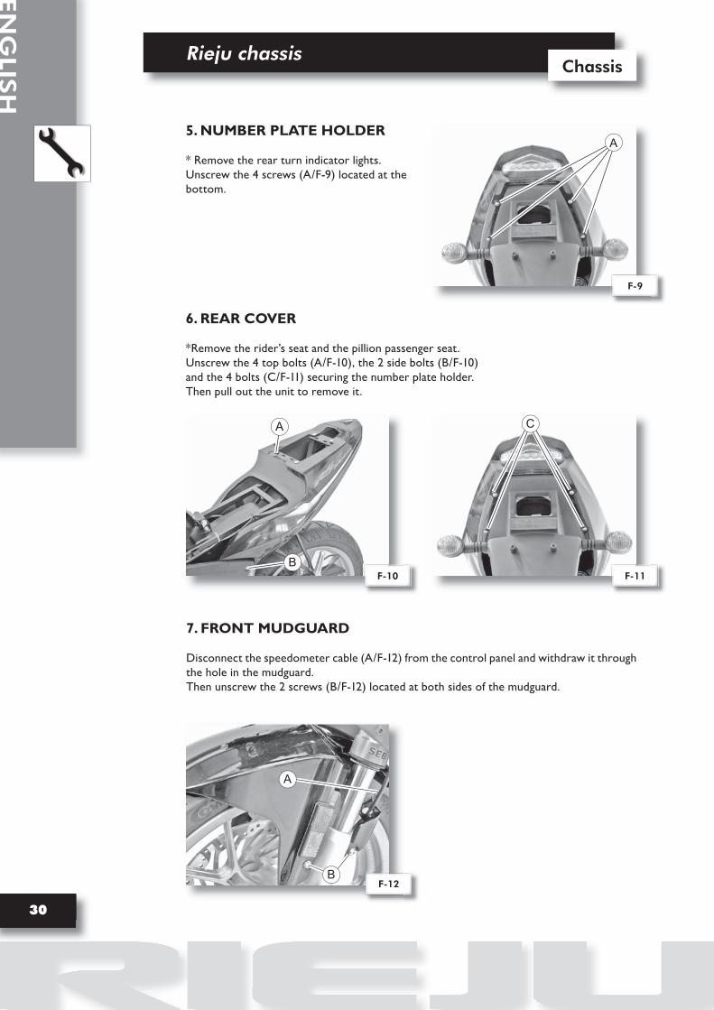
7. FRONT MUDGUARD
Disconnect the speedometer cable (A/F-12) from the control panel and withdraw it through the hole in the mudguard.Then unscrew the 2 screws (B/F-12) located at both sides of the mudguard.
F-12B
A
6. REAR COVER
*Remove the rider’s seat and the pillion passenger seat.Unscrew the 4 top bolts (A/F-10), the 2 side bolts (B/F-10) and the 4 bolts (C/F-11) securing the number plate holder.Then pull out the unit to remove it.
F-10
A
BF-11
C
5. NUMBER PLATE HOLDER
* Remove the rear turn indicator lights.Unscrew the 4 screws (A/F-9) located at the bottom.
F-9
A

Rieju chassis
31
Chassis
EN
GLI
SH
8. FUEL TANK
Remove the clips securing the pipe (B/F-14).Remove the pipes from the tap.Disconnect the fuel level sensor (A/F-13).Unscrew the bolt (C/F-15) securing the tank to the chassis.Then remove the tank by pulling it upwards.
F-13 F-14
F-16
F-15
C
9. FUEL TANK PROTECTORUnscrew the 5 screws (A/F-16) at the top. Then unscrew the 2 bolts (B/F-17) at the back and remove the protector.
F-17
BA
DANGER OF FIREOperations that could start a fire.
DANGER OF EXPLOSION Operations that could set off an explosion.
A B

EN
GLIS
H
Rieju chassisChassis
32
11. STEERING
Unscrew the 2 bolts (A/F-21) on the sides of the handlebars.
Extract the top nut (B/F-21) and remove the top plate.
To extract the shaft, unscrew the nut (C/F-21).
F-21
BCA
A
10. HANDLEBARS
* Remove the controls on each end.
Unscrew the 2 side bolts (A/F-18-19) and remove the right and left handlebars.
F-18
A
F-19
A
F-20
NAKED version.
* Remove the controls on both sides.Unscrew the 4 screws (B/F-20).
B

Rieju chassis
33
Chassis
EN
GLI
SH
Disconnect the clutch cable (A/F-22) and the choke cable (B/F-22).
Then unscrew the 2 bolts (C/F-22) and remo-ve the lever.
12. CLUTCH LEVER
A
B
F-22
Disconnect the brake light microswitch terminals.
Unscrew the connector (A/F-23) securing the pipe to the brake cylinder.
Then, unscrew the 2 bolts (B/F-24) and remove the front brake cylinder.
ATTENTION: when reassembling, it is recommended to renew the copper seals and bleed the circuit.
ATTENTION: Brake fluid is abrasive.
13. FRONT BRAKE CYLINDER
F-23
A
F-24
B
C

EN
GLIS
H
Rieju chassisChassis
34
14. FRONT HEADLIGHT
* Remove the front headlight holder.Disconnect the wires.Then unscrew the 2 bolts (A/F-25) securing the headlight to the headlight holder.
ATTENTION: Pay attention to the position of the wires, to enable subsequent re-assembly.
A
F-25
NAKED version.
Disconnect the headlight from the general wiring. Then unscrew the 2 screws (B/F-26) on the sides.
B
F-26
15. FRONT INDICATOR LIGHTS
Unscrew the bolt (A/F-27), while holding the nut on the inside. Then disconnect the light (B/F-28) from the general wiring.
ATTENTION: Pay attention to the position of the wires, to enable subsequent re-assembly.
F-27 F-28
BA

Rieju chassis
35
Chassis
EN
GLI
SH
16. REAR LIGHT
* Remove the rear cover.Cut the clip securing the wires and disconnect from the general wiring.Then loosen the 2 bolts (A/F-30) securing the light to the mudguard.To extract it, pull the wire to withdraw the light.
ATTENTION: Before proceeding to dismantle the lights, pay attention to the sequence of the terminals, to enable subsequent re-assembly (see wiring diagram).
F-29 F-30
A
17. REAR INDICATOR LIGHTS
Cut the clip securing the wires (A/F-31) and disconnect from the general wiring.Then loosen the screw (B/F-32) and pull the wire to withdraw the light.
ATTENTION: Before proceeding to dismantle the lights, pay attention to the sequence of the terminals, to enable subsequent re-assembly (see wiring diagram).
F-31 F-32
A B

EN
GLIS
H
Rieju chassisChassis
36
18. INSTRUMENT PANEL
* Remove the front headlight holder.
Disconnect the speedometer cable (A/F-33).Then unscrew the 3 bolts (B/F-33) securing the screen to the support.
A
F-33
B
NAKED version.
Disconnect the instrument panel.
Then unscrew the 2 screws.
RS2 MATRIX version.
F-34
ATTENTION: Remember to reconnect the earth wire when reassembling.
A
19. TURN INDICATOR REGULATOR
Disconnect the regulator from the wiring (A/F-35).
F-35

Rieju chassis
37
Chassis
EN
GLI
SH
20. CONTACT RELAY
Disconnect the contact relay (A/F-36) from the general wiring.Then extract it from the holding rubber.
A
F-36
21. CONTROL UNIT (CDI)
Unscrew the 2 securing screws (A/F-37) and then disconnect from the wiring.
A
F-37 F-38

EN
GLIS
H
Rieju chassisChassis
38
22. BATTERY
* Remove the pillion passenger seat.Disconnect the two wires (red positive and black negative).Withdraw the securing rubber and then remove the battery by pulling it upwards.
F-39
23. OIL SENSOR
* Remove the seat and the rear cover.Disconnect the sensor from the wiring and pull the sensor upwards to remove it.
F-40
24. OIL TANK
* Remove the seat and the rear cover, and dis-connect the level sensor.Disconnect the pipe from the tank.Then unscrew the 2 bolts (B/F-41) securing the tank to the chassis and remove it.
F-41
B
ATTENTION: Before proceeding with the dismantling, drain the oil from the tank.

Rieju chassis
39
Chassis
EN
GLI
SH
25. AIR FILTER
* Remove the seat and the rear cover.Unscrew the 3 filter cover bolts (A/F-42) and remove the filter.
F-42 F-43
A
26. FUEL TRANSMISSION/OIL MIXER
Unscrew the 2 cover screws (A/F-44).Pull back the sensor and remove the fuel cable.
27. “AIS” SYSTEM (Secondary air valve)
Disconnect clips (A/F-46).Unscrew the 2 securing bolts (B/F-47).
F-47
BF-46
A
F-44 F-45A

EN
GLIS
H
Rieju chassisChassis
40
28. EXHAUST
Disconnect the breather pipe (AIS system) (A/F-48) and remove the exhaust pipe by pulling out forwards.Remove the 2 springs (B/F-48) securing the exhaust pipe to the engine at the front.Unscrew the screw (F/F-51) securing the exhaust.Unscrew the clip (C/F-49) securing the exhaust pipe to the chassis.
ATTENTION: Before proceeding to dismantle the exhaust pipe, make sure it has cooled down.
29. SILENCER
Unscrew the bolt (D/F-50) securing the silencer to the chassis.Then, Loosen the 3 nuts (E/F-51) securing the silencer to the exhaust pipe.To extract the silencer, pull it backwards.
ATTENTION: Before proceeding to dismantle the silencer, make sure it has cooled down.
C
F-49F-48
A
B
D
F-50 F-51
E
F
Rieju chassis
41
Chassis
EN
GLI
SH
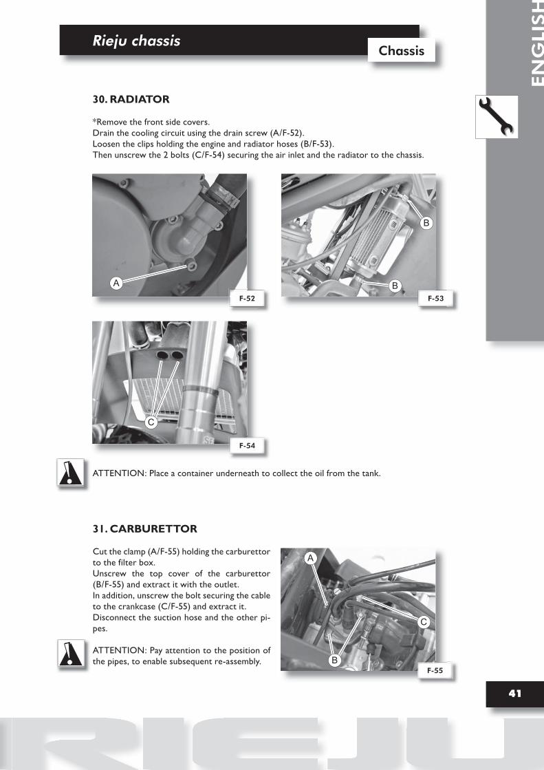
31. CARBURETTOR
Cut the clamp (A/F-55) holding the carburettor to the filter box.Unscrew the top cover of the carburettor (B/F-55) and extract it with the outlet. In addition, unscrew the bolt securing the cable to the crankcase (C/F-55) and extract it.Disconnect the suction hose and the other pi-pes.
ATTENTION: Pay attention to the position of the pipes, to enable subsequent re-assembly.
A
F-55
C
B
30. RADIATOR
*Remove the front side covers.Drain the cooling circuit using the drain screw (A/F-52).Loosen the clips holding the engine and radiator hoses (B/F-53).Then unscrew the 2 bolts (C/F-54) securing the air inlet and the radiator to the chassis.
ATTENTION: Place a container underneath to collect the oil from the tank.
B
BF-53F-52
A
F-54
C

EN
GLIS
H
Rieju chassisChassis
42
32. GEAR CHANGE LEVER
Remove the cotter pin (A/F-56) from the rod.Then unscrew the bolt (B/F-56) securing the gear-change lever to the chassis.
F-56
A
B
33. REAR BRAKE LEVER
Unscrew the 2 bolts (A/F-57) and withdraw the rear brake lever assembly.
F-57
A

Rieju chassis
43
Chassis
EN
GLI
SH
34. SIDE STAND
ATTENTION: Ensure the moped is suitably secured before performing this operation.
Remove the tensioning spring (A/F-58).Then, unscrew the 2 bolts (B/F-58).
F-58
B
A
ATTENTION: Brake fluid is abrasive.
35. REAR BRAKE CYLINDER
Unscrew the 2 bolts (A/F-59) securing the brake cylinder to the support.
Remove the clamp (B/F-59) from the brake fluid supply pipe and drain it into a container.
F-59
A
B
36. REAR BRAKE CALLIPER
* Remove the rear wheel.
Unscrew the connector using the bolt (A/F-60).
ATTENTION: When reassembling, it is re-commended to renew the copper seals and bleed the circuit.
F-60
A

EN
GLIS
H
Rieju chassisChassis
44
B
C
F-62
F-64
37. ENGINE
Disconnect the 2 pipes from the cylinder head heater, unscrew the screws from the suction pipe (A/F-61) and separate the connector from the spark plug. Disconnect the heat switch wire.Disconnect the neutral position wire (G/F-64), located at the bottom of the engine, the magneto wires and the central unit wires.Unscrew the screws from the oil mixer cover and disconnect the transmission (A/F-44) - see page 39.
Drain the cooling circuit using the drain screw (B/F-62).
Disconnect the hose (C/F-62) from the cylinder head to radiator and pump to radiator.
Remove the 2 self-locking nuts and remove the 2 bolts (D/F-63) securing the engine.
Loosen the bolt (E/F-64) and tilt the bracket forwards.Then remove the self-locking nut (F/F-64) and remove the bolt securing the engine.
ATTENTION: Leave the bottom bolt until last.
F-61
A
F-63
E
F
D
G

Rieju chassis
45
Chassis
EN
GLI
SH
38. REAR WHEEL
Loosen the driving chain and withdrawing it from the dish of the wheel.Then unscrew the axle (A/F-65) and to pull it to withdraw it.
39. CHAIN PROTECTOR
Unscrew the 2 bolts (A/F-66) on both sides and remove the protector.
F-66A
40. DRIVE CHAIN
Remove the 2 protector securing bolts (A/F-67) and remove it.
Extract the link securing clip (B/F-68) and remove it.
Chain tensioning (See page 26).
F-67 F-68
A
B
F-65
A

EN
GLIS
H
Rieju chassisChassis
46
41. SHOCK ABSORBER
* Remove the rear cover.Unscrew the 2 bolts (A/F-69) securing the shock absorber to the chassis.Then extract it from behind.
ATTENTION: Before dismantling, secure the chassis at the bottom to prevent the swinging arm and wheel from falling.
ATTENTION: Pay attention to the position of the shock absorber, to enable subsequent re-assembly.
F-69
A
A
42. SWING ARM
* Remove the chain, rear wheel, rear brake calliper and shock absorber.
Remove the caps on both sides, unscrew the nut (A/F-70) and remove the axle from the right hand side.
F-70
A

Rieju chassis
47
Chassis
EN
GLI
SH
43. FRONT WHEEL
ATTENTION: Loosen the axle securing bolts (A/F-71) located on the forks.
Unscrew the axle (B/F-71) from the wheel and withdraw it.
Unscrew the connector using the bolt (A/F-72).
Then unscrew the 2 bolts (B/F-72) securing the calliper to the front forks.
ATTENTION: When reassembling, it is recom-mended to renew the copper seals and bleed the circuit.
44. FRONT BRAKE CALLIPER
F-72
A
B
45. FRONT BRAKE DISK
*Remove the front wheel.
Unscrew the bolts (A/F-73) securing the disk.
F-73
A
AF-71
B

EN
GLIS
H
Rieju chassisChassis
48
Unscrew the bolt and disconnect from of the other end.
47. FRONT FOOTRESTS
Remove the clip (A/F-75) and then withdraw the cotter pin (B/F-75) in order to extract the footrest.
ATTENTION: Make a note of the position of the spring to enable subsequent reassembly.
F-75
A
B
46. SPEED SENSOR
48. REAR FOOTRESTS BRACKET
Unscrew the 2 bolts (A/F-76) securing the brac-ket to the chassis.
F-76
A
F-74
A
Rieju chassis
49
Chassis
EN
GLI
SH
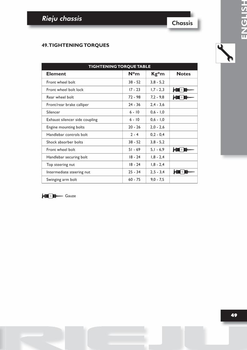
49. TIGHTENING TORQUES
Front wheel bolt
Front wheel bolt lock
Rear wheel bolt
Front/rear brake calliper
Silencer
Exhaust silencer side coupling
Engine mounting bolts
Handlebar controls bolt
Shock absorber bolts
Front wheel bolt
Handlebar securing bolt
Top steering nut
Intermediate steering nut
Swinging arm bolt
Element Kg*mN*m Notes
38 - 52
17 - 23
72 - 98
24 - 36
6 - 10
6 - 10
20 - 26
2 - 4
38 - 52
51 - 69
18 - 24
18 - 24
25 - 34
60 - 75
3,8 - 5,2
1,7 - 2,3
7,2 - 9,8
2,4 - 3,6
0,6 - 1,0
0,6 - 1,0
2,0 - 2,6
0,2 - 0,4
3,8 - 5,2
5,1 - 6,9
1,8 - 2,4
1,8 - 2,4
2,5 - 3,4
9,0 - 7,5
TIGHTENING TORQUE TABLE
G
G Gauze
G
G
G


1
Chassis
EN
GLI
SH
Index
ELECTRIC SYSTEM
1. DASHBOARD PROGRAMMING
2. ELECTRIC DIAGRAM 2003
3. ELECTRIC DIAGRAM 2006
3
5
6


Electric system
3
Chassis
EN
GLI
SH
1. DASHBOARD PROGRAMMING
DASHBOARD
The dashboard contains two buttons in its right side, the upper one is to select “SET” and the lower one for the function “MODE.”
SET THE CLOCK
• Put the key in the IGNITION position, with the engine turned off.• Wait three seconds and the INITIAL screen will appear on the DISPLAY.• Press the button “Mode” for 6 seconds, and the digit to be selected (hours) will be flickered.• With the button “Set”, select the suitable number.• Once the hour is selected, press the button “Mode” again and the digits corresponding to the minutes will be flickered.• Select with the button “Set” and press the button “Mode” again turning back to the Initial screen.
INSERTION OF THE PARAMETERS OF CALCULATION IN THE ODOMETER MEMORY
• Development of the wheel that sets the signal sensor.• Pulses of the signal sensor.• Pulses of Revolutions.
Put the key in the IGNITION position with the engine turned off.• Wait three seconds and the INITIAL screen will appear on the DISPLAY.
• Press the button “MODE”, and without releasing it, press the button “SET” for one second, automatically the word “SET” will be displayed on the screen to be able to insert the values.

EN
GLIS
H
Electric system Chassis
4
Rear Tyre
Circumference Wheel
Pulses of the Sensor (screws)
Pulses of RPM
• The first value is the development of the wheel and it should be inserted in mm.
• Pressing the button “SET” we select the digit, and with the button “MODE” pressed for three seconds we pass to the next digit, and using this sequence we insert the fixed development to that wheel.
• Keeping the button “Mode” pressed for 3 seconds, the screen of the Display will request us for the pulses, with the word “PULSE”, following the sequence insert the value.
• We keep the button “Mode” pressed and the option of miles, (mph) and kilometres hour (km / h) will be displayed, then we will choose km / h with the button “SET”.
• Following the sequence, the word “PULSE” will appear on the screen and above it “RPM”, we will insert the value corresponding to the RPM.
Keeping the button “MODE” pressed for 3 seconds more, we will turn back to the INITIAL screen.
TO CHECK IF THE INPUT DATA IS THE RIGHT ONE, WE SHOULD TURN ON THE IGNITION, START THE ENGINE AND IN TWO SECONDS THE ENTERED DATA WILL BE DISPLAYED ON THE SCREEN DURING TWO SECONDS, VERIFYING THAT IT IS CORRECT, IMMEDIATELY AFTER THE INITIAL SCREEN WILL APPEAR.
The dashboard is ready to be used giving the right information.
SET OF VALUES VALUES TO BE INSERTED IN THE DISPLAY CONFIGURATION
RS2 50 cc. MATRIX RS2 50 cc. MATRIX PRO
130/70-17
1930
5
3

Electric system
5
Chassis
EN
GLI
SH
2. ELECTRIC DIAGRAM 2003
0/000.160.7000/7004

EN
GLIS
H
Electric system Chassis
6
3. ELECTRIC DIAGRAM 2006
0/000.160.7008/7009


Index
1
Engine
EN
GLI
SH
INTRODUCTION
NOTES FOR EASY CONSULTATION 6
GENERAL WORK PROCEDURES 7
RECOMMENDATIONS 8
SPARK PLUGS 10
ENGINE RIEJU
EQUIPMENT KIT 14
LUBRICANTS 14
ENGINE DISASSEMBLY 15
MAINTENANCE 22
ENGINE ASSEMBLY 26
ENGINE SERVICINGAND COMMISSIONING SCHEDULE 33
PARTS AND THEIR TORQUE WRENCH SETTINGS 34
EXPLODED VIEW OF THE ENGINE AM6 EURO2 35

Introduction

3
EN
GLI
SH
IntroductionIntroduction

EN
GLIS
H
IntroductionEngine
4
• All checks, maintenance, repairs or replacements, etc. on the vehicles manufactured by Ma-laguti are to be performed by skilled and expert technical personnel with specific experience in sta-te-of-the-art technology and full knowledge of the quickest and most rational procedures, technical characteristics, setting values and tightening torques, which may only be properly and exhaustively provided by the manufacturer.
• This set of WORKSHOP MANUALS concerning two-stroke engines provides technicians of the sector (Authorised Service Centres, etc.), the essential information for operating in accordance with the latest good working practices and work safety regulations.
• These publications provide all necessary information for routine procedures on all the RIEJU-motor vehicles equipped with two-stroke engines currently in production at the date of issue. The information provided deals with the motor vehicle ENGINES. Some basic technical information has been intentionally omitted as it is considered to be common knowledge.
• Additional information is available in the SPARE PARTS CATALOGUES of each model.
• It is important that before referring to the specific engine manual, the information given in this general section be carefully read as it provides all the essential hints and guidelines for best consulting the various topics and main technical subjects.
Note:These manuals provide the necessary information and instructions for routine maintenance and servicing. This information has been given to us by the engine manufacturers. We therefore decline all responsibility for any error, omission or misrepresentation. RIEJU reserves the right to make any changes and modifications hereto it deems necessary without prior notice.For further information and details, please contact the RIEJU, S.A. Service Division.
1.1 MANUAL UPDATES
• The updates will be sent by us ( in a reasonable time). Every Cd-Rom you will receive, will super-sede the one already in your hands.
• The table of contents will be duly updated in the event that new pages are inserted, which ren-der the consultation of the manual difficult.
• IMPORTANT! The Workshop Manuals are to be considered as essential tools to be properly kept up-to-date so as to maintain their “ validity” over time.
Introduction
5
Engine
EN
GLI
SH
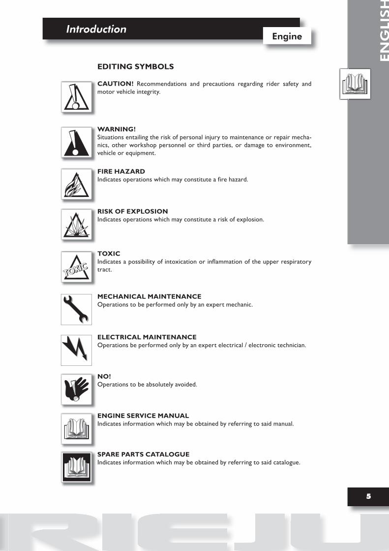
EDITING SYMBOLS
CAUTION! Recommendations and precautions regarding rider safety and motor vehicle integrity.
WARNING!Situations entailing the risk of personal injury to maintenance or repair mecha-nics, other workshop personnel or third parties, or damage to environment, vehicle or equipment.
FIRE HAZARDIndicates operations which may constitute a fire hazard.
RISK OF EXPLOSIONIndicates operations which may constitute a risk of explosion.
TOXICIndicates a possibility of intoxication or inflammation of the upper respiratory tract.
MECHANICAL MAINTENANCEOperations to be performed only by an expert mechanic.
ELECTRICAL MAINTENANCEOperations be performed only by an expert electrical / electronic technician.
NO!Operations to be absolutely avoided.
ENGINE SERVICE MANUALIndicates information which may be obtained by referring to said manual.
SPARE PARTS CATALOGUEIndicates information which may be obtained by referring to said catalogue.
TOXICTOXICTOXIC

EN
GLIS
H
IntroductionEngine
6
Note:The letter Tr in the illustrations refers to retaining or adjusting screws. The number following this letter refers to the number of the same type of screw in the unit or component described and illustrated. Letters not followed by a number indicate a single screw . In case of different screws being referred to in the illustration, the letter Tr is followed by a number and a small letter , for instance: (Tr4a).
Unless otherwise specified, units and components are reassembled by pro-ceeding in the reverse order of removal.
OPERATIONAL SYMBOLS
L) Loctite
O) Oil lubrication
G) Greasing
O
L
G
F
Pr Tr
PAp
S
Es
T
Tr
Figure
Tightening torque
PageParagraph
Section
Diagram
Table
Screw

Introduction
7
Engine
EN
GLI
SH
1.3 GENERAL WORK PROCEDURES
• The advice, recommendations and warnings given hereafter are aimed at ensuring maximum work safety as well as at considerably reducing the risk of accidents, personal injury, equipment damage and idle times. They should therefore be strictly adhered to.
ADVICE:• Only use quality tools and equipment.
• Only use equipment conforming to EU Directives for lifting the vehicle.
• During operations, always keep tools and equipment at hand, possibly laying them out according to the sequence in which they are to be used. Absolutely avoid putting them on the vehicle itself, out-of-sight or in poorly accessible places.
• Always keep the work area clean and tidy.
•When tightening screws or nuts, start with the larger diameter or inner fasteners, and tighten them in progressive “pulls” in accordance to a “criss-cross” pattern.
• Preferably use open-end box wrenches by “pulling” and not “pushing”.
• Adjustable wrenches (F-1) should only be used in case of emergency, i.e. when a properly sized wrench is not available. They should preferably not be used as the movable jaw tends to open thus risking damaging or not properly tightening the bolt to the correct torque. In any case, when using an adjustable wrench, take care to proceed as shown in Figure 1.
• Except for occasional customers, always make out and deliver to the customer a work sheet specifying the operations performed, with notes as to any future checks eventually required.
F-1

EN
GLIS
H
IntroductionEngine
8
1.4 WARNINGS
• Before carrying out any operation on the vehicle, wait for all parts to cool down.
• For operations requiring two mechanics, make sure that the various steps to be performed by each of them are clearly defined and coordinated beforehand.
• Make sure that each component has been properly fitted before proceeding with the next one.
• Lubricate all parts (where applicable) before reinstalling them.
• Gaskets, O-rings, circlips and split pins must be replaced at every refitting.
• The torque settings specified in the manuals refer to the “final torque”, which must be attained progressively by steps.
• Loosen and tighten aluminium alloy parts (covers) only after the engine has fully cooled down.
• Only use screwdrivers with sizes suitable to the screws to be loosened or tightened.
• Work in a comfortable position and ensure that the vehicle is stable.
• Never use a screwdriver as a lever or chisel.
• Never use pincers to loosen or tighten screws or nuts because, in addition to not providing a sufficient clamping force, they may also damage the screw head or nut hexagon.
• Never tap the wrench with a hammer or other similar tools to loosen or tig-hten screws and nuts (F-2).
• Never attempt to increase the lever arm by fitting a tube into the wrench (F-3).
F-2 F-3

Introduction
9
Engine
EN
GLI
SH
Never use open flames for any reason.
Never leave open containers or containers not suitable for holding fuel in passageways, close to heatsources, etc
Never use petrol to clean the vehicle or the floor of the workshop. Always use low flash point solvents to clean the vehicle components.
Never suck from or blow into the fuel pipe.
When welding, make sure that there are no flammable liquids in the vicinity. Always re-move the tank, even if completely empty, and disconnect the negative cable (-) from the battery.
Never leave the engine running in closed or poorly ventilated areas.
Before any servicing, make sure that the motorbike is perfectly stable.The front wheel should preferably be anchored to the equipment (A/F-4) integral with the lifting board.
F-4
EN
GLIS
H
IntroductionEngine
10
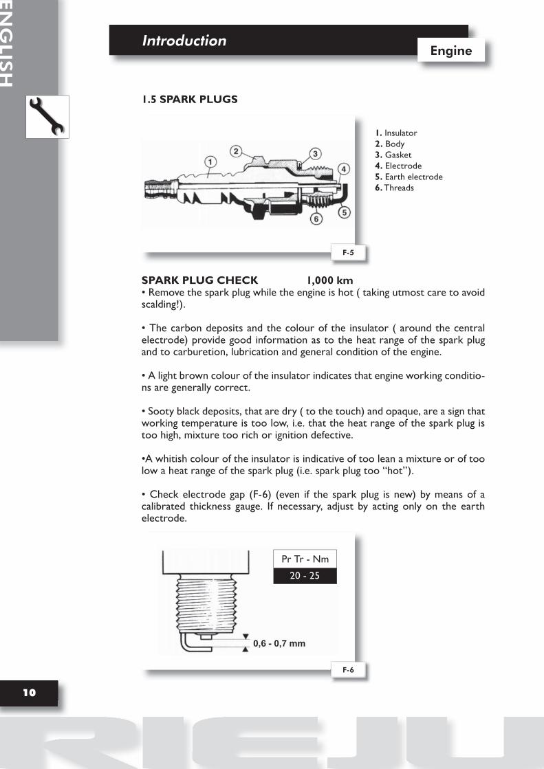
1.5 SPARK PLUGS
1. Insulator2. Body3. Gasket4. Electrode5. Earth electrode6. Threads
SPARK PLUG CHECK 1,000 km• Remove the spark plug while the engine is hot ( taking utmost care to avoid scalding!).
• The carbon deposits and the colour of the insulator ( around the central electrode) provide good information as to the heat range of the spark plug and to carburetion, lubrication and general condition of the engine.
• A light brown colour of the insulator indicates that engine working conditio-ns are generally correct.
• Sooty black deposits, that are dry ( to the touch) and opaque, are a sign that working temperature is too low, i.e. that the heat range of the spark plug is too high, mixture too rich or ignition defective.
•A whitish colour of the insulator is indicative of too lean a mixture or of too low a heat range of the spark plug (i.e. spark plug too “hot”).
• Check electrode gap (F-6) (even if the spark plug is new) by means of a calibrated thickness gauge. If necessary, adjust by acting only on the earth electrode.
F-5
F-6
Pr Tr - Nm
20 - 25

Introduction
11
Engine
EN
GLI
SH
SPARK PLUG MAINTENANCE
• Spark plug maintenance consists essentially of a periodical visual inspection. Remove the spark plug and check for proper condition and gap.
• Clean the electrodes and the insulator thoroughly by means of a wire brush.
• Remove any residual dirt with a strong jet of compressed air.
• Lubricate spark plug thread with engine oil or graphitised grease, and install it by hand until finger tight.Tighten to the specified torque with a spark plug wrench (see F-6).
It is imperative that any spark plug exhibiting cracks on the insulator or corro-ded electrodes be replaced.
SPARK PLUG REPLACEMENT 5000 km
• Upon prescribed mileage being reached, always replace the spark plug. Use RIEJU, S.A. recommended spark plugs.
• When replacing exhausted spark plugs, visually inspect spark plug condition as described above to ascertain whether or not the engine is running properly.
ENGINE REMOVAL
• For removal of the engine from the chassis, refer to the “Chassis” Workshop Manual, which lists all the operations required.
ENGINE DISASSEMBLY
The manufacturer declines all responsibility for damage of any kind caused by disassembly and reassembly of the engine and its parts if unsuitable tools are used.
Use only ORIGINAL RIEJU SPARE PARTS.

Engine RIEJU

13
EN
GLI
SH
Engine RIEJUEngine RIEJU

EN
GLIS
H
Engine RiejuEngine
14
2.1 EQUIPMENT KIT
Code RIEJU 0/000.640.9999
2.2 LUBRICANTS
LUBRICANTS TABLE
LUBRICANTS FOR TWO-STROKE ENGINE
1) Synthetic mix oil
2) Gearbox oil SAE 10W30, type SE
GENERAL PURPOSE LUBRICANTS
3) Grease for moving parts
GENERAL PURPOSE LUBRICANTSGENERAL PURPOSE LUBRICANTS

Engine Rieju
15
Engine
EN
GLI
SH
ESPA
ÑO
L
2.3 DISASSEMBLY OF THE ENGINE
After removing the spark-plug and carburettor proceed as follows:
1) DRAIN the engine oil by removing the relevant drain bolt.
2) UNSCREW the coolant drainage screw (1/F-1); remove the water pump cover by undo-ing the two fixing screws (2/F-1). Pay attention to the dowel bolts (1/F-2).
3) UNDO the fixing screws of the flywheel cover (left hand side) and remove it.Remove the starter motor (if fitted) by removing the two screws on the crankcase and the screw on the support strap.
4) Take the carburettor out of its seat; remove the intake union and the relative clutch “brid-ge”; remove the plate group (1/F-3).
5) REMOVE the sprocket (1/F-4) by removing the snap ring (2/F-4); using ring pliers, remove the sprocket by hand and remove the other snap ring underneath the sprocket.
F-1 F-2
F-3 F-4

EN
GLIS
H
Engine RiejuEngine
16
6) REMOVE the sliding stop screw for starting from clutch side (1/F-5).
7) REMOVE the fixing screws of the plastic oil pump cap (1/F-6). Undo the screws securing the oil pump to the cover; then remove the pump.
8) REMOVE the cover/crankcase fixing screws (of which one M6x55 (2/F-6), that secure the water pump cover and the relative clutch cover to the crankcase); now remove the cover (3/F-6) and its gasket.
9) TAKE the starter assembly OUT of its seat (only for versions with starter pedals), bearing in mind that the any shim washers must be put in the same position when the com-ponent is reassembled.
CAUTION: when disassembling this group, carefully check the position of the pieces so as to reassemble them correctly afterwards.
10) UNDO the screws compressing the clutch springs (1/F-7); then remove the clutch pla-te (2/F-7) and the entire set of discs (3 /F-7); remove the disc pusher, the ball and the clutch rod (1, 2, 3/F-8), which are housed in the centre hole of the change shaft.
F-6F-5
F-7 F-8

Engine Rieju
17
Engine
EN
GLI
SH
ESPA
ÑO
L11) DISENGAGE the nut from its fixing tab (1/F-9); using the appropriate wrench (1/F-10), unscrew and remove the fixing nut (2/F-10) of the clutch boss.
12) REMOVE the following pieces in this order: clutch boss (1/F-11), spacer (2/F-11), clutch gear (3/F-11), shim washer (1/F-12), tapered washer (2/F-12), paying attention to the direc-tion in which they are assembled so as to reassemble them correctly afterwards.
13) USING the magneto flywheel locking wrench (1/F-13), lock the flywheel and slacken the retaining nut of the gear on the countershaft with the wrench (1/F-14).
14) REMOVE the gear on the countershaft (1/F-14) and the key.
F-10F-9
F-11 F-12
F-13 F-14

EN
GLIS
H
Engine RiejuEngine
18
15) UNSCREW the nut (2/F-14) with a 19 mm wrench, whilst holding the flywheel in place with the special wrench; then remove the following parts in this order: drive pinion, countershaft drive gear, key, spacer bushing and O-ring.
16) BLOCKING the rotor of the magneto flywheel with the special locking wrench (1/F-15), unscrew the rotor retaining nut with a 15 mm wrench.
17) REMOVE the rotor of the magneto flywheel by means of the appropriate puller (1/F-16), which must be screwed into the threaded seat of the rotor; whilst holding the latter in place with a wrench, turn the centre screw.
18) REMOVE the stator by undoing the screws that secure it to the plate (1/F-17).
19) TAKE the stator plate OUT of its seat by removing the 3 screws that secure it to the crankcase (2/F-17), and remove the key (3/F-17).
F-16F-15
F-17

Engine Rieju
19
Engine
EN
GLI
SH
ESPA
ÑO
L
20) DISASSEMBLING the thermal section:a) unscrew the 4 cylinder head holding nuts and remove the relevant washers; remove the head, its O-ring, the cylinder, the cylinder gasket and the four O-ring on the stud bolts.
CAUTION: before removing the circlips of the piston pin, put a clean cloth into the opening on the crankcase, to prevent the circlips dropping into the engine.
21) REMOVE the two circlips (F-18), remove the piston pin and, if you intend to use a 2-diameter plug, knock gently taking care to hold the piston on the opposite side in order to avoid damaging the connecting rod.
22) REMOVE the 13 screws joining the two crankcases (F-19) and take the clutch pin out of its seat.
23) SEPARATE the 2 crankcases by gentling tapping the secondary shaft and shift shaft with a wooden mallet.
IMPORTANT: if you need to take the crankshaft out of its seat, use the spe-cial tool (1/F-20).
24) Once the crankcases have been separated, CHECK that the shim washers are on the shafts and not on the crankcase that has just been removed (F-21).
F-19F-18
F-20 F-21
EN
GLIS
H
Engine RiejuEngine
20
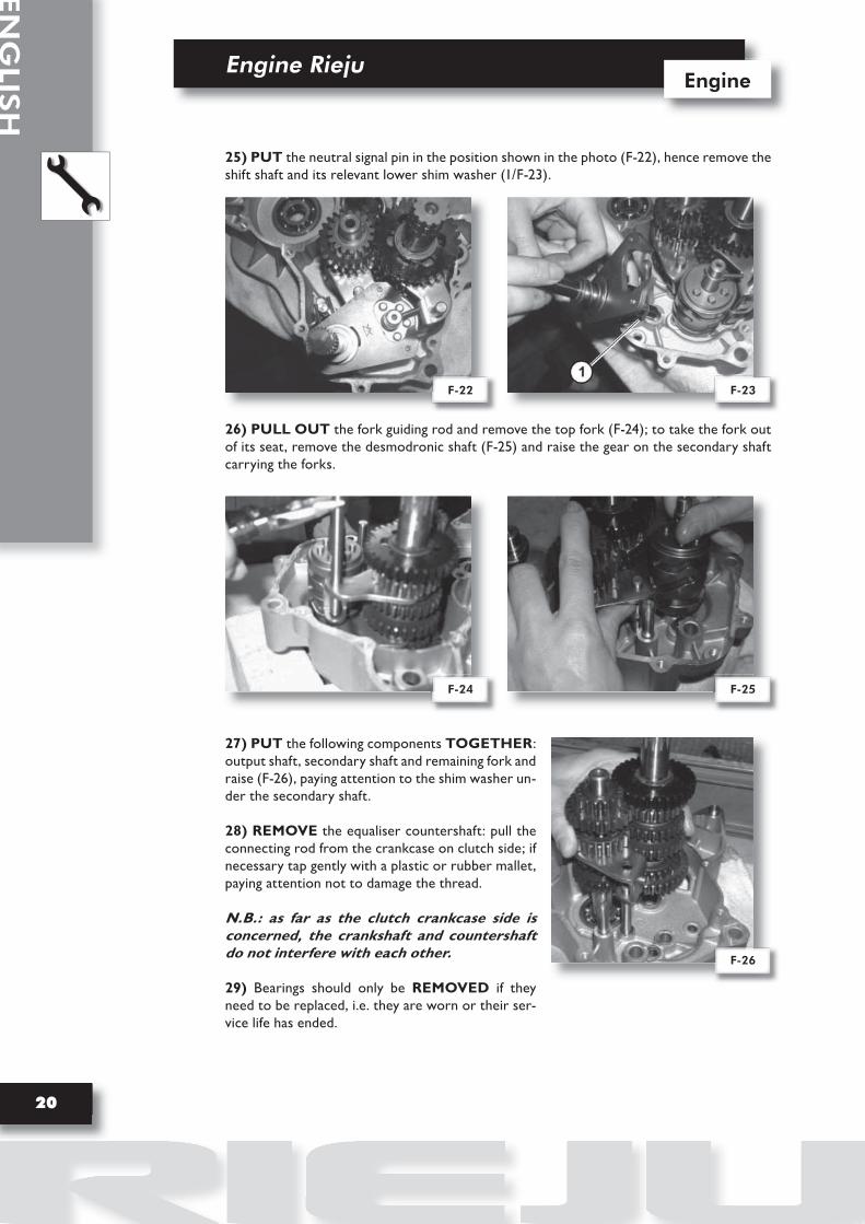
25) PUT the neutral signal pin in the position shown in the photo (F-22), hence remove the shift shaft and its relevant lower shim washer (1/F-23).
26) PULL OUT the fork guiding rod and remove the top fork (F-24); to take the fork out of its seat, remove the desmodronic shaft (F-25) and raise the gear on the secondary shaft carrying the forks.
27) PUT the following components TOGETHER: output shaft, secondary shaft and remaining fork and raise (F-26), paying attention to the shim washer un-der the secondary shaft.
28) REMOVE the equaliser countershaft: pull the connecting rod from the crankcase on clutch side; if necessary tap gently with a plastic or rubber mallet, paying attention not to damage the thread.
N.B.: as far as the clutch crankcase side is concerned, the crankshaft and countershaft do not interfere with each other.
29) Bearings should only be REMOVED if they need to be replaced, i.e. they are worn or their ser-vice life has ended.
F-23F-22
F-24 F-25
F-26

Engine Rieju
21
Engine
EN
GLI
SH
ESPA
ÑO
L
30) IF the oil pump needs to be replaced, proceed as follows (F-27):
a) Detach the oil pump supply pipe (1) and put a plug into it to prevent oil leaks.
b) Detach the oil delivery pipe leading from the pump to the carburettor (2).
c) Disconnect the control cable fastened to the pump’s lever (3).
d) Undo the pump fixing screws (4) and remove the pump.
e) Fit the new pump in its seat and replace the O-ring.
f) Plug the oil delivery pipe (2) into the new pump.
g) Plug the oil supply pipe (1) into the pump.
h) Take the purge screw and gasket off the pump (5) and let the oil containing air bubbles leak out. Wait until only oil is leaking out. Purging can thus be considered accomplished. You can now refit the screw in place.
I) Reconnect the control cable (3) to the pump lever, making sure that the idle position of the throttle grip on the handlebar corresponds to the idle position of the lever; otherwise, make any necessary adjustments by means of the adjustment screw.
F-27

EN
GLIS
H
Engine RiejuEngine
22
2.4 MAINTENANCE
GENERAL WARNINGSBefore reassembling the engine either totally or partially, thoroughly clean the parts by washing them with petrol, drying them with compressed air and making sure that they are sufficiently oiled and in perfect working order.
It is always advisable to replace the gaskets because old ones may be leaky. We recom-mend you always replace the engine oil seals: they may have been damaged during disas-sembly and this could adversely affect engine operation. Always use the special plugs to ensure correct assembly of the oil seals.
A) Secondary gear shaft oil seal:- Secondary gear shaft oil seal assembly plug.
B) Connecting rod oil seal:- Connecting rod oil seal assembly plug, clutch side.- Connecting rod oil seal assembly plug, flywheel side.
C) Clutch lever oil seal:- Clutch lever oil seal assembly plug.
D) Shift shaft oil seal:- Shift shaft oil seal assembly plug.
E) Water pump oil seal:- Water pump oil seal assembly plug.
Check carefully that the pieces are whole and arrange all the various groups of gears in such a way that assembly may be carried out correctly.

Engine Rieju
23
Engine
EN
GLI
SH
ESPA
ÑO
L
PREVENTIVE CARE
1) WASH the two crankcases and the bearings with petrol and blow them with compres-sed air, checking that the bearings run freely and noiselessly.
CAUTION: if it should be necessary to replace a bearing, the seat must be heated before installing the new bearing.
2) MAKE SURE the connecting rod is in perfect working order and check for faults, espe-cially in the bearing seats. Make sure assembly on flywheel side has been properly accomplis-hed. Using a comparator, check the eccentricity of the two connecting rod axle shafts. The maximum eccentricity value must not exceed 0.04 mm. On the contrary, centre accordingly. Make sure the connecting rod is perpendicular.
3) MAKE SURE the transmission is in perfect working order and fit the shim washers in the right positions. If you have replaced components, make sure that they are put in the same positions as the parts removed and that the end float does not exceed 0.1 mm. To obtain this condition, measure the distance of the shim washers on the crankcase and com-ponents, and fill any gaps with other shim washers, as shown in the photo (F-28).
4) CHECK the distance of the shim washer of the desmodronic shaft both on the crankcase and on the part, and fill any gaps with other shim washers, as shown in the photo (F-29).The end float must be less than 0.1 mm.
5) CHECK the distance of the shim washers of the shift shaft both on the crankcase and on the part, and fill any gaps with other shim washers, as shown in the photo (F-30). The end float must be less than 0.1 mm.
F-29F-28
F-31F-30

EN
GLIS
H
Engine RiejuEngine
24
6) ENSURE that the clutch assembly is in working order.To do so, ensure that the iron discs are in good condition, that the notches on the cork discs are not too deformed and that their coating is not burnt. Check that the grooves on the clutch boss are not too deeply marked; perform the same check on the slots of the clutch housing. Also check that the clutch springs are not shorter than the permissible threshold of 29.5 mm (F-31); if they are shorter replace them.
7) CAREFULLY clean the carbon crust from the piston top by means of a common scra-per, taking care not to damage the piston itself. Check the piston skirt for streaks or seizing. Check that it is firmly mated to the lubricated piston pin, the surface of which must be in perfect condition. Make sure that the piston pin can be fitted by manual pressure and that it does not yield under its own weight.
8) CHECK the piston rings for faults of any type and make sure that the clearance between the two ends is within the values shown in the chart.
The checks must be carried out using a feeler gauge. The piston ring must be placed in the cylinder in a horizontal position (F-32).
9) CHECK that the cylinder water jacket does not have seizing notches or wear and that there is no scoring of any kind. By means of a bore gauge, check the cylinder bore in two directions at 90° the one from the other (one parallel and the other perpendicular to the axis of the piston pin) (F-33). The maximum permissible ovalisation is 0.03 mm, exceeding which the cylinder must be replaced.
F-33F-32
RINGS DISTANCE
New
Used
0,15 ÷ 0,30 mm
Up to 1,2 mm

Engine Rieju
25
Engine
EN
GLI
SH
ESPA
ÑO
L
Repeat the measurements in several positions along the cylinder jacket, between the top face of the cylinder and the exhaust gap (F-34).
Then check the diameter of the piston and compare it with that of the cylinder (F-33).
The maximum end float is 0.10 mm, exceeding which, the piston should be replaced. See the chart below.
Important: maintain the same identification letters on the cylinder and piston. The cylinder identification lettercan be found on the flat surface of the oiler.
10) WATER PUMPa) Place the clutch crankcase (right hand side) on a flat surface.b) Fit the oil seal in the right direction, as shown (F-35).c) Fit the impeller, gasket, dowels and water pump cover.
F-34F-34
ENGINE TYPE MIN/MAX PLAY
AM6 50 (WATER COLLED)
(CAST IRON CYLINDER)
0.049
0.062
-0,063 -0,057
-0,056 -0,050
-0,049 -0,043
-0,007 -0,002
-0,001 -0,006
-0,007 -0,012
Y
Z
V
TOLE. PISTON TOLE. CYLINDER SELECTION
COUPLING CHART
F-35
POSITION THE THERMOSTATHOLE, ASSHOWN
(CYLINDER IN GHISA)

EN
GLIS
H
Engine RiejuEngine
26
2.5 ENGINE REASSEMBLY
1) PLACE the clutch crankcase (right hand side) on a flat surface. Then, fit the spring and the gear selection poppet ball in their seats and apply grease to prevent them falling out.
2) PREPARE the transmission assembly (primary/secondary) keeping all components to-gether (F-36). Put a 0.6 mm shim washer under the 1st speed gear and position the fork in the 3rd and 4th primary gear (F-36).
LOWER the assembly thus formed into its seats (F-37).Raise the 5th speed gear on the secondary shaft and insert the fork (F-38). Fit the other fork (6th speed gear) into its seat (F-39).
F-37F-36
F-39F-38
G

Engine Rieju
27
Engine
EN
GLI
SH
ESPA
ÑO
L
3) FIT the desmodronic shaft (F-40). Insert the fork guide pins into the desmodronic shaft (F-41).Fit the fork guide rod into its seat (F-42).
Turn the desmodronic shaft until it reaches the position shown in the figure (F-43).
N.B.: these operations must be effected without forcing (with a hammer or other tools).
F-41F-40
F-43F-42

EN
GLIS
H
Engine RiejuEngine
28
4) INSERT the shift shaft with the lower washers (0.6 mm thick) (1/F-44) and insert the return spring hooks in the relevant anchoring bridge (F-45) then check that:
- By putting the desmodronic shaft in 3rd speed, make sure the rollers of the cam are at an equal distance from the fork hooks. On the contrary, slightly bend the ends of the spring until obtaining the requested condition.
5) FIT the countershaft in the clutch crankcase.N.B.: assembly of the countershaft in its seat implies no interference.
6) If it has been removed, FIT the connecting rod in the crankcase on flywheel side using the tool (1/F-46); keep the connecting rod at the T.D.C. whilst tightening the screw, until the connecting rod touches the bearings.
7) FIT the dowel bolts (1-2/F-47), apply gasket paste on the mating sides of the crankcases (F-47) and oil all shafts. Place the crankcase (flywheel side) over the other crankcase and tap gently all over with a wooden, leather or plastic mallet until the crankcases are joined.
8) FIT the 13 fixing screws and tighten in place (Cs 1.0 ÷ 1.2 kg*m). Make sure all shafts can turn freely. Make sure that none of the shafts feature excessive end play, in which case, separate the crankcases and replace the top shim washer with another having a more sui-table thickness.
9) FIT the new oil seals, using the specific plug for each.
F-45F-44
F-47F-46

Engine Rieju
29
Engine
EN
GLI
SH
ESPA
ÑO
L
10) FIT the key for the magneto flywheel; put the stator in its seat and fasten in place with the fixing screws (Cs 0.25 ÷ 0.3 kg*m). Fit the rotor and tighten the nut (Cs 4.3 ÷ 4.5 kg*m), using the usual wrench (F-48).
11) FIT the sprocket: snap ring (1/F-49) - sprocket (2) - snap ring (1) - fit the clutch control pin (3/F-49) with its return spring (4/F-49).
12) CHECK operation of the sprocket and gear wheel pair.If any of the gears needs to be replaced, it is recommended to replace the pair since this will ensure smoother and quieter operation.
13) FIT the crankshaft (clutch side) in the following order:1) The overturned oil seal (1/F-50), using the special plug (2/F-50)2) The O-ring (1/F-51)3) The spacer (2/F-51), with the bevelled side facing the crankshaft. Push in place until it stops.
Now fit the key (1/F-52), the countershaft drive gear (2/F-52), the drive sprocket and the nut (Cs 6.7 ÷ 7.5 kg*m). Fit the key and driven gear on the countershaft (2/F-53), making sure that the reference notches on the two gears match (F-53). Tighten the nut (Cs 4.5 ÷ 5.0 kg*m) (apply Loctite 242).
F-49F-48
F-50
L
F-51

EN
GLIS
H
Engine RiejuEngine
30
14) PROCEED in reverse order. Refit the clutch assembly and remember to replace the nut fixing washer with a new one; fit the clutch boss fixing nut (Cs 5.5 ÷ 6.0 kg*m) and bend the tab.
15) FIT the following components on the output shaft, in the order given: clutch rod (grea-se beforehand), ball and disc pusher.
16) FIT the clutch disc assembly in the order shown in (F-54); the iron discs (1-2-3/F-54) should be fitted with the notch, highlighted by the arrows, at 120° the one from the other, starting from the notch facing upwards on the first disc. Fit the last clutch disc, making sure it is timed with the boss (F-54b).
F-54bF-54
F-52
F-53
F-55

Engine Rieju
31
Engine
EN
GLI
SH
ESPA
ÑO
L
17) FIT the springs and fixing screws and tighten (Cs 0.3 ÷ 0.5 kg*m).
18) Correct operating position of the clutch is obtained when the lever, in the position indicated by the arrow (F-55), is parallel to the cover resting surface.To obtain this condition, turn the adjustment screw (1/F-56) on the last disc, using the spe-cial wrench (2/F-56). Tighten the nut (Cs 2.6 ÷ 2.8 kg*m) .
19) BEFORE fitting the starter assembly (version without an electric starter), make sure that the phase between the pawl on the sliding rod and the hole for fixing the spring is the same as before disassembly (90° - F-57).
20) FIT the starter assembly, whilst hooking the spring to the hub on the cover.
21) FIT: the dowel bolts and a new gasket on the crankcase; the clutch cover; if necessary, this operation can be made easier by turning the impeller of the water pump. Secure in place with screws (Cs 1.0 ÷ 1.2 kg*m).If you have disassembled it, refit the oil pump, making sure that the O-ring is in working order (1/F-58a).
When refitting, take care not to damage the oil pump gear.
Whilst fitting the starter lever on its shaft, turn it 180° counter-clockwise and secure in place with the fixing screws (Cs 2.9 ÷ 3.0 kg*m) (F-58b).This operation must be performed to pre-load the return spring.
F-57F-56
F-58bF-58a

EN
GLIS
H
Engine RiejuEngine
32
22) Before assembly, CHECK the condition of the cage on the piston pin and its rollers.Fit the piston, making sure that the arrow marked on the top is facing towards the ex-haust side (F-59), and therefore towards the piston pin and its circlips.
23) In the order indicated, FIT the piston rings, making sure that the ends are correctly positioned in the seats on the piston; a new cylinder gasket; the cylinder; the centre cylinder O-ring in the stud bolts; the O-ring on the cylinder head; the head (clean beforehand). Tig-hten the nuts evenly and diametrically (Cs 1.4 ÷ 1.6 kg*m); check the position and tightness of the O-ring on the cylinder head.
24) FIT the reed valve (F-60), followed by the exhaust manifold, tightening the four screws evenly and diametrically (Cs 0.9 ÷ 1.1 kg*m).
25) REFIT the flywheel cover, a new gasket and its fixing screws, which must be tightened (Cs 0.1 ÷ 0.2 kg*m).
26) REFIT the oil drainage bolt, replace the gasket and secure firmly in place (Cs 1.7 ÷ 1.8 kg*m).
27) POUR oil into the engine (0.750 kg) through the hole at the top.
F-60F-59

Engine Rieju
33
Engine
EN
GLI
SH
ESPA
ÑO
L
2.6 ENGINE SERVICING AND COMMISSIONING SCHEDULE
AFTER 1000 KM OR 3 MONTHS
EVERY 5000 KM
MAINTENANCE OPERATIONS
X X X X X X X X X X
X X XX
X
X
XXX
X
X X X X X X X X X X X XXXX
XXXXXX
every 10.000kmevery 10.000kmevery 10.000km
X
XXX
X
X
Check
Adjustment of engine idling speedGas and oil pump controlFront and rear brake controlOperation of the electrical equipmentPetrol ductsOil ductsFront and rear brake liquid ductsCoolant ductFuel heating ductTire pressureTire condition, pressure and wear Level of front and rear brake liquidLevel of coolantLevel of battery electrolyte Screw tightnessBattery charge level
Replace
Air filter filtering element Front and rear brake pads Gearbox oilChain - pinion - gear wheel Clutch discs Spark plug
Check and/or replace
PistonCylinder headDischarge gap
Check and lubricate
Chain tightness and condition
Check and adjust
Clutch controlOil pump controlHeadlinght height
Clean and adjust
Carburettor
Vehicle test
Road test

EN
GLIS
H
Engine RiejuEngine
34
2÷2,5
1,4÷1,6
2,4÷2,6
1,6÷2,0
4,5÷5,0
0,25÷0,35
0,4÷0,6
0,4÷0,6
0,4÷0,6
0,4÷0,6
0,6÷0,8
0,3÷0,4
0,9÷1,1
1,0÷1,2
0,2÷0,4
1,0÷1,2
1,7÷1,8
0,1÷0,2
2,4÷ 2,6
1,0÷ 1,2
0,1÷0,2
6,5÷7,5
5,5÷6,6
0,3÷0,5
2,6÷2,8
1,4÷1,6
0,3÷0,4
4,3÷4,5
2.7 PARTS AND THEIR TORQUE WRENCH SETTINGS
PART POSITION PART NAME SCREWS TORQUE SETTING
N*m Kg*mQTY.
Spark plug
Cylinder head
Cylinder head
Cylinder head
Countershaft
Water cooling (head)
Water pump body
Pipe coupling
Water pump body
Water pump body
Oil pump
Oil pump lid
Intake manifold
Crankcase
Cover, clutch side
Crankcase, flywheel side
Crankcase, clutch side
Crankcase, flywheel side
Crankcase, clutch side
Cover, clutch side
Cover, flywheel side
Primary gear (Clutch side)
Clutch boss
Disc boss (clutch)
Disc pusher (clutch)
Selector
Magneto flywheel
Magneto flywheel
Spark plug
Nut
Pipe fitting
Temperature probe
Hex. nut
T.C.B. screw
T.C.C.E. screw
T.C.C.E. screw
T.C.C.E. screw
T.C.B. screw
T.C.C.E. screw
T.C.C.E. screw
T.C.C.E. screw
Stud bolt
T.C.B. screw
T.C.C.E. screw
Hex. screw
Neutral indicator light
Hex. screw
T.C.C.E. screw
T.C.C.E. screw
Nut
Hex. screw
T.C.C.E. screw
Hex. nut
Clutch adj. screw
Hex. nut
Screw
Hex. nut
14 x 1.25
M7 x 1
M8 x 1.25
M14 x 1.25
M12 x 1
M4 x 0.7
M6 x 1
M6 x 1
M6 x 1
M6 x 1
M5 x 0.8
M5 x 0.8
M6 x 1
M7 x 1
M6 x 1
M6 x 1
M8 x 1.25
M10 x 1.25
M12 x 1.25
M6 x 1
M5 x 0.8
M12 x 1.25
M12 x 1.25
M5 x 0.8
M14 x 1.25
M14 x 1.25
M7 x 1
M4 x 0.7
M10 x 1.25
1
4
1
1
1
2
1
1
1
1
2
2
4
4
1
13
1
1
1
7
5
1
1
4
1
1
1
3
1
1
2
3
4
5
6
7
8
9
10
11
12
13
14
15
16
17
18
20
21
22
23
24
25
26
27
28
29
30
20÷25
14÷16
24÷26
16÷20
45÷50
2,5÷3,5
4÷6
4÷6
4÷6
4÷6
6÷8
3÷4
9÷11
10÷12
2÷4
10÷12
17÷18
1÷2
24÷26
10÷12
1÷2
65÷75
55÷60
3÷5
26÷28
14÷16
3÷4
43÷45
L
O
O
O
turn until it stops

Engine Rieju
35
Engine
EN
GLI
SH
ESPA
ÑO
L
2.8 EXPLODED VIEW OF THE ENGINE AM6 EURO2

RIEJU, S.A. c/.Borrassà, 41 E-17600 FIGUERES, GIRONA (SPAIN) Telf. +34 / 972500850 Fax +34 / 972506950 www.riejumoto.com / e-mail [email protected]
RS2 50 MATRIX-NAKED