lft11099 pegasus aircare mattress system … 2200 220… · pegasus aircare mattress overlay system...
TRANSCRIPT
User Guide
Pegasus™ AircareMattress Overlay System
Models 2200 and 2201
LFT11099 Issue 3
PEGASUS AIRCAREMattress Overlay System
Models 2200 and 2201
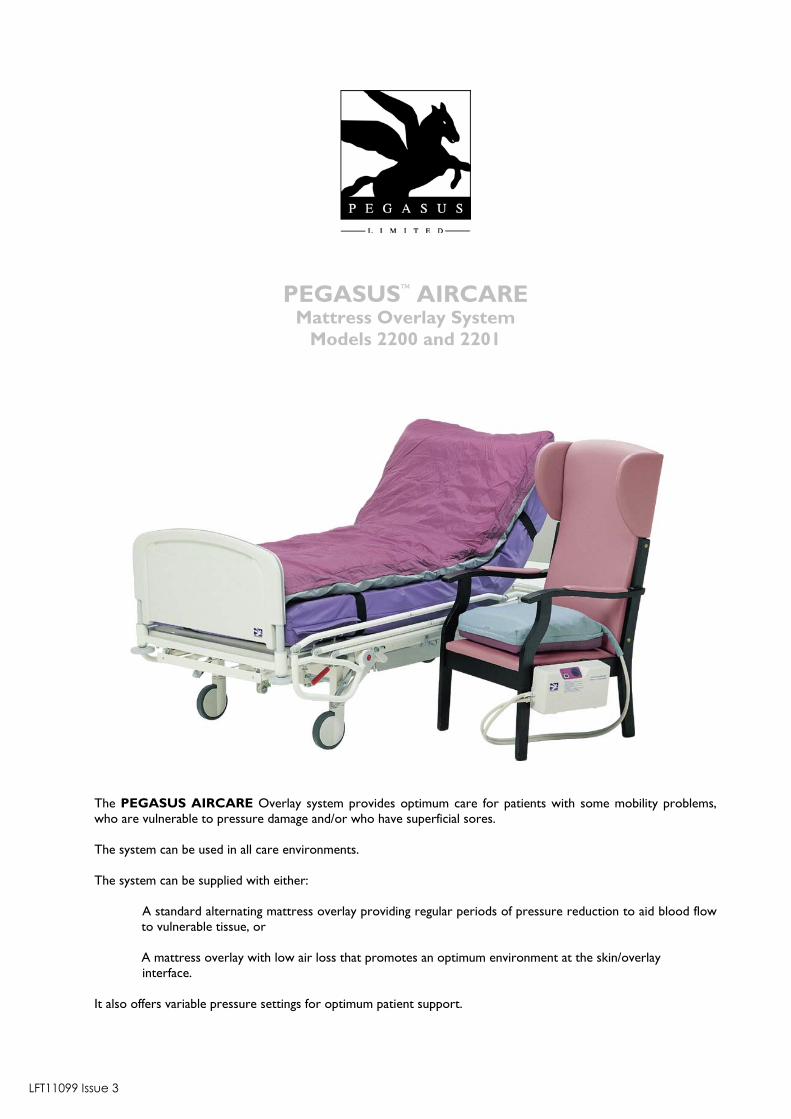
The PEGASUS AIRCARE Overlay system provides optimum care for patients with some mobility problems,who are vulnerable to pressure damage and/or who have superficial sores.
The system can be used in all care environments.
The system can be supplied with either:
A standard alternating mattress overlay providing regular periods of pressure reduction to aid blood flowto vulnerable tissue, or
A mattress overlay with low air loss that promotes an optimum environment at the skin/overlay interface.
It also offers variable pressure settings for optimum patient support.
LFT11099 Issue 3
1
PEGASUS AIRCAREMattress Overlay System
Models 2200 and 2201
TABLE OF CONTENTS
SECTION PAGE
A LIST OF PARTS 2
B GENERAL 3Introduction 3System Description 3
C SETTING UP/OPERATION 4Setting Up 4Operation 5Removal 5
D CPR/REANIMATION 6System Running Normally 6Moving the Bed/Power Cuts 7
E MOVING THE BED AND POWER CUTS 7Mattress 7Power Unit 7
F ALARMS AND FAULTFINDING 7Alarms 7Faultfinding 8
G INFECTION CONTROL AND CLEANING 9Infection Control 9Cleaning Guidelines 9
H TECHNICAL SPECIFICATIONS 11
2
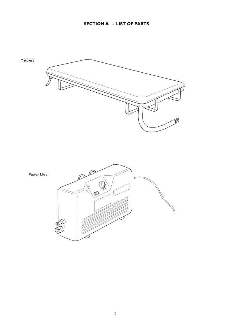
SECTION A - LIST OF PARTS
Mattress
Power Unit
3
SECTION B - GENERAL
INTRODUCTION
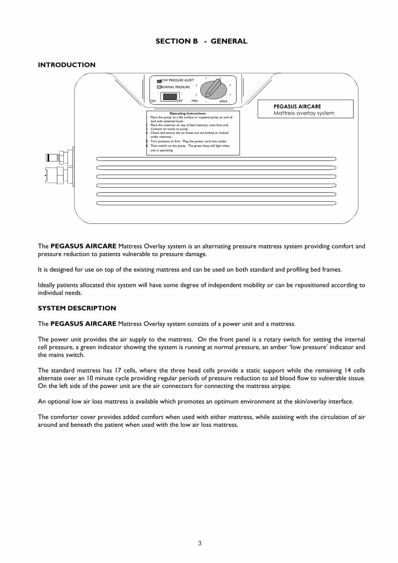
The PEGASUS AIRCARE Mattress Overlay system is an alternating pressure mattress system providing comfort andpressure reduction to patients vulnerable to pressure damage.
It is designed for use on top of the existing mattress and can be used on both standard and profiling bed frames.
Ideally patients allocated this system will have some degree of independent mobility or can be repositioned according toindividual needs.
SYSTEM DESCRIPTION
The PEGASUS AIRCARE Mattress Overlay system consists of a power unit and a mattress.
The power unit provides the air supply to the mattress. On the front panel is a rotary switch for setting the internalcell pressure, a green indicator showing the system is running at normal pressure, an amber ‘low pressure’ indicator andthe mains switch.
The standard mattress has 17 cells, where the three head cells provide a static support while the remaining 14 cellsalternate over an 10 minute cycle providing regular periods of pressure reduction to aid blood flow to vulnerable tissue.On the left side of the power unit are the air connectors for connecting the mattress airpipe.
An optional low air loss mattress is available which promotes an optimum environment at the skin/overlay interface.
The comforter cover provides added comfort when used with either mattress, while assisting with the circulation of airaround and beneath the patient when used with the low air loss mattress.
Operating Instructions:1. Place the pump on a flat surface or suspend pump on end of
bed with attached hook.2. Place the mattress on top of bed mattress, note foot end.3. Connect air hoses to pump.4. Check and ensure the air hoses are not kinked or tucked
under mattress.5. Turn pressure to firm. Plug the power cord into outlet.6. Then switch on the pump. The green lamp will light when
unit is operating.
NORMAL PRESSURE
MAXON OFF MIN
LOW PRESSURE ALERT
PEGASUS AIRCAREMattress overlay system
4
SECTION C - SETTING UP/OPERATION
SETTING UP
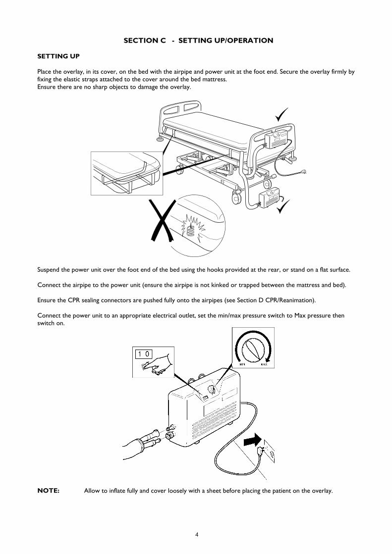
Place the overlay, in its cover, on the bed with the airpipe and power unit at the foot end. Secure the overlay firmly byfixing the elastic straps attached to the cover around the bed mattress.Ensure there are no sharp objects to damage the overlay.
Suspend the power unit over the foot end of the bed using the hooks provided at the rear, or stand on a flat surface.
Connect the airpipe to the power unit (ensure the airpipe is not kinked or trapped between the mattress and bed).
Ensure the CPR sealing connectors are pushed fully onto the airpipes (see Section D CPR/Reanimation).
Connect the power unit to an appropriate electrical outlet, set the min/max pressure switch to Max pressure thenswitch on.
NOTE: Allow to inflate fully and cover loosely with a sheet before placing the patient on the overlay.
5
OPERATION
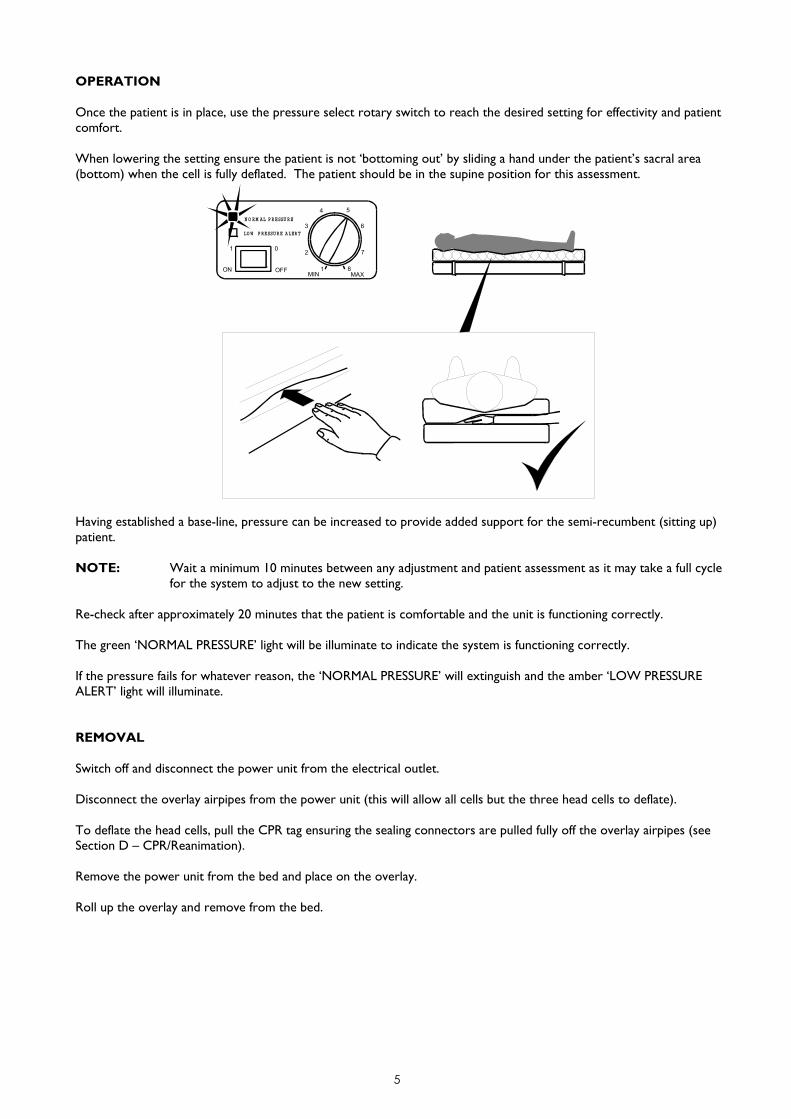
Once the patient is in place, use the pressure select rotary switch to reach the desired setting for effectivity and patientcomfort.
When lowering the setting ensure the patient is not ‘bottoming out’ by sliding a hand under the patient’s sacral area(bottom) when the cell is fully deflated. The patient should be in the supine position for this assessment.
MAXMIN1 8
N O RM AL PRESSU RE
LO W PRESSURE ALERT
2
3
4
7
6
5
OFF
01
ON
Having established a base-line, pressure can be increased to provide added support for the semi-recumbent (sitting up)patient.
NOTE: Wait a minimum 10 minutes between any adjustment and patient assessment as it may take a full cyclefor the system to adjust to the new setting.
Re-check after approximately 20 minutes that the patient is comfortable and the unit is functioning correctly.
The green ‘NORMAL PRESSURE’ light will be illuminate to indicate the system is functioning correctly.
If the pressure fails for whatever reason, the ‘NORMAL PRESSURE’ will extinguish and the amber ‘LOW PRESSUREALERT’ light will illuminate.
REMOVAL
Switch off and disconnect the power unit from the electrical outlet.
Disconnect the overlay airpipes from the power unit (this will allow all cells but the three head cells to deflate).
To deflate the head cells, pull the CPR tag ensuring the sealing connectors are pulled fully off the overlay airpipes (seeSection D – CPR/Reanimation).
Remove the power unit from the bed and place on the overlay.
Roll up the overlay and remove from the bed.
6
SECTION D - CPR/REANIMATION
Deflation of the overlay may be required for emergency procedures. To deflate the overlay quickly carry out theappropriate following procedure:
SYSTEM RUNNING NORMALLY
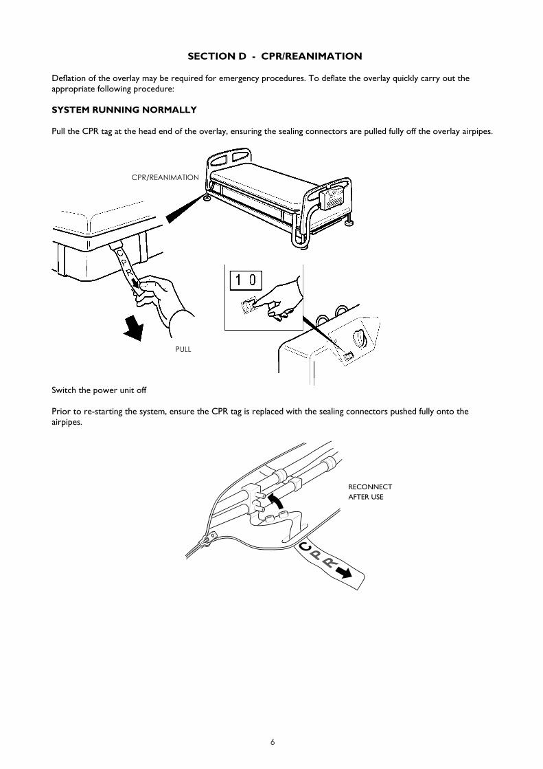
Pull the CPR tag at the head end of the overlay, ensuring the sealing connectors are pulled fully off the overlay airpipes.
Switch the power unit off
Prior to re-starting the system, ensure the CPR tag is replaced with the sealing connectors pushed fully onto theairpipes.
RECONNECTAFTER USE
CPR/REANIMATION
PULL
7
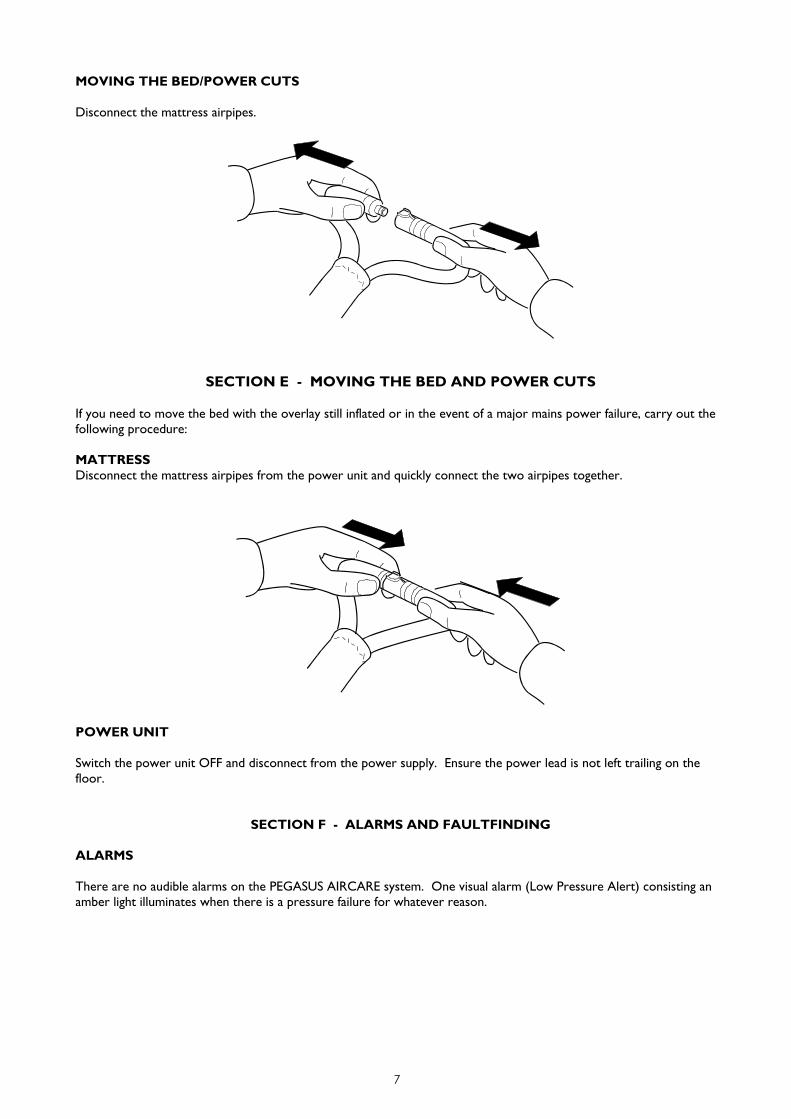
MOVING THE BED/POWER CUTS
Disconnect the mattress airpipes.
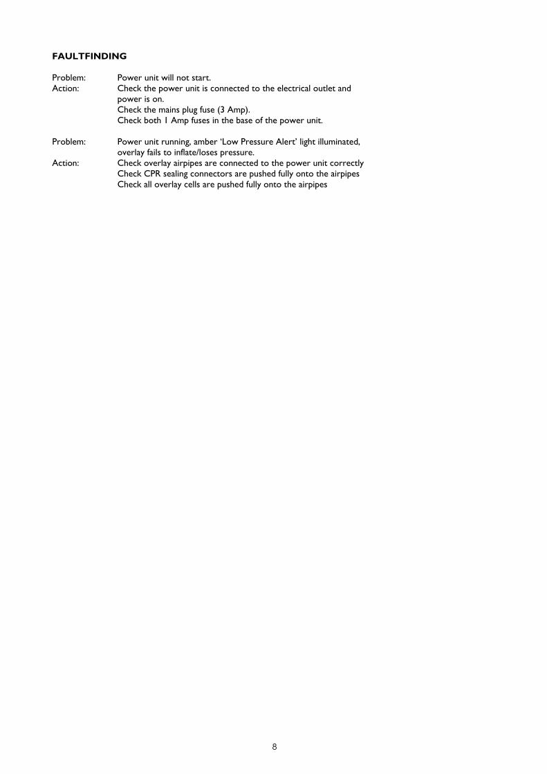
SECTION E - MOVING THE BED AND POWER CUTS
If you need to move the bed with the overlay still inflated or in the event of a major mains power failure, carry out thefollowing procedure:
MATTRESSDisconnect the mattress airpipes from the power unit and quickly connect the two airpipes together.
POWER UNIT
Switch the power unit OFF and disconnect from the power supply. Ensure the power lead is not left trailing on thefloor.
SECTION F - ALARMS AND FAULTFINDING
ALARMS
There are no audible alarms on the PEGASUS AIRCARE system. One visual alarm (Low Pressure Alert) consisting anamber light illuminates when there is a pressure failure for whatever reason.
8
FAULTFINDING
Problem: Power unit will not start.Action: Check the power unit is connected to the electrical outlet and
power is on.Check the mains plug fuse (3 Amp).Check both 1 Amp fuses in the base of the power unit.
Problem: Power unit running, amber ‘Low Pressure Alert’ light illuminated,overlay fails to inflate/loses pressure.
Action: Check overlay airpipes are connected to the power unit correctlyCheck CPR sealing connectors are pushed fully onto the airpipesCheck all overlay cells are pushed fully onto the airpipes
9
SECTION G - INFECTION CONTROL AND CLEANING
INFECTION CONTROL
Infection Control and routine cleaning must be carried out in accordance with your local Infection Control Policy.
CLEANING GUIDELINES
WARNINGS: Ensure the power unit is disconnected from the mains electricity supply before cleaning.
Do not immerse the power unit in water.
CAUTION: Do not high temperature autoclave, or use Phenolic based products for cleaning
It is recommended the system is cleaned between users or approximately every 2 weeks if in constant use.
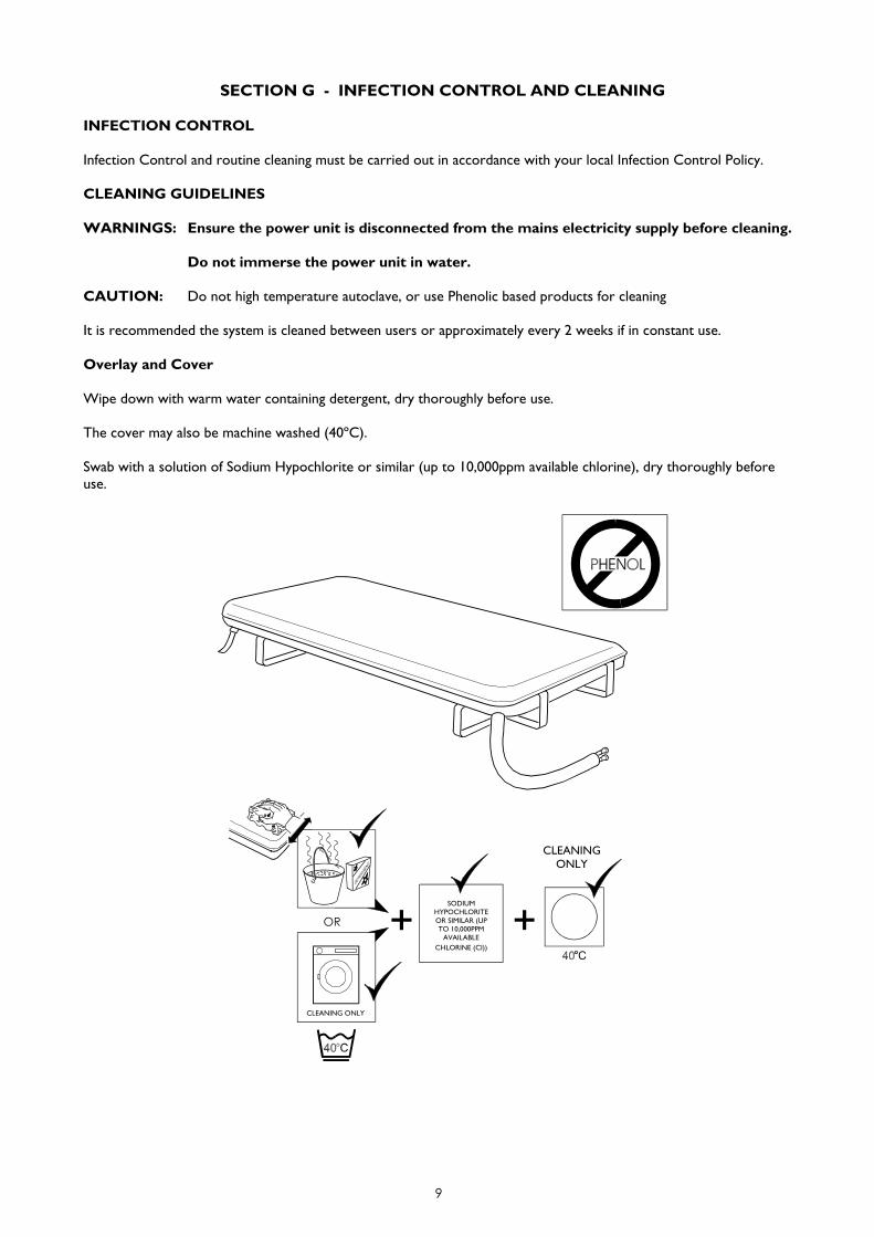
Overlay and Cover
Wipe down with warm water containing detergent, dry thoroughly before use.
The cover may also be machine washed (40ºC).
Swab with a solution of Sodium Hypochlorite or similar (up to 10,000ppm available chlorine), dry thoroughly beforeuse.
SODIUMHYPOCHLORITEOR SIMILAR (UPTO 10,000PPM
AVAILABLECHLORINE (CI))
OR
CLEANINGONLY
CLEANING ONLY
10
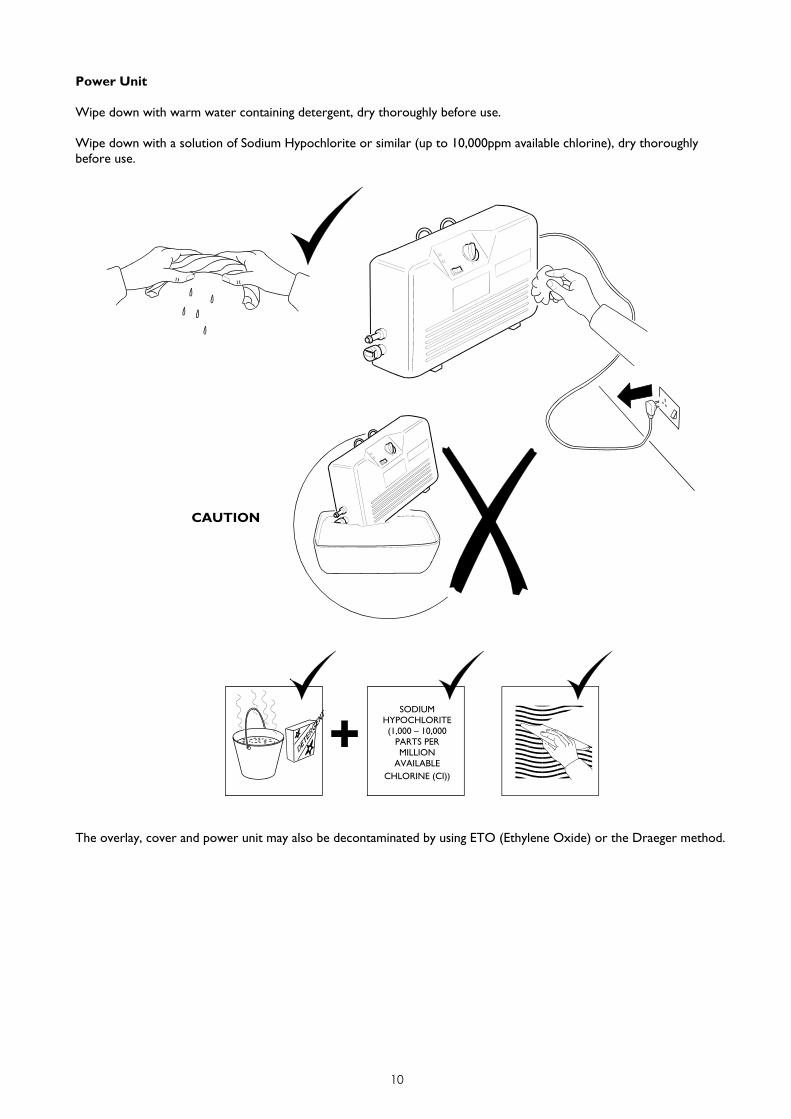
Power Unit
Wipe down with warm water containing detergent, dry thoroughly before use.
Wipe down with a solution of Sodium Hypochlorite or similar (up to 10,000ppm available chlorine), dry thoroughlybefore use.
The overlay, cover and power unit may also be decontaminated by using ETO (Ethylene Oxide) or the Draeger method.
CAUTION
SODIUMHYPOCHLORITE(1,000 – 10,000
PARTS PERMILLION
AVAILABLECHLORINE (CI))
11
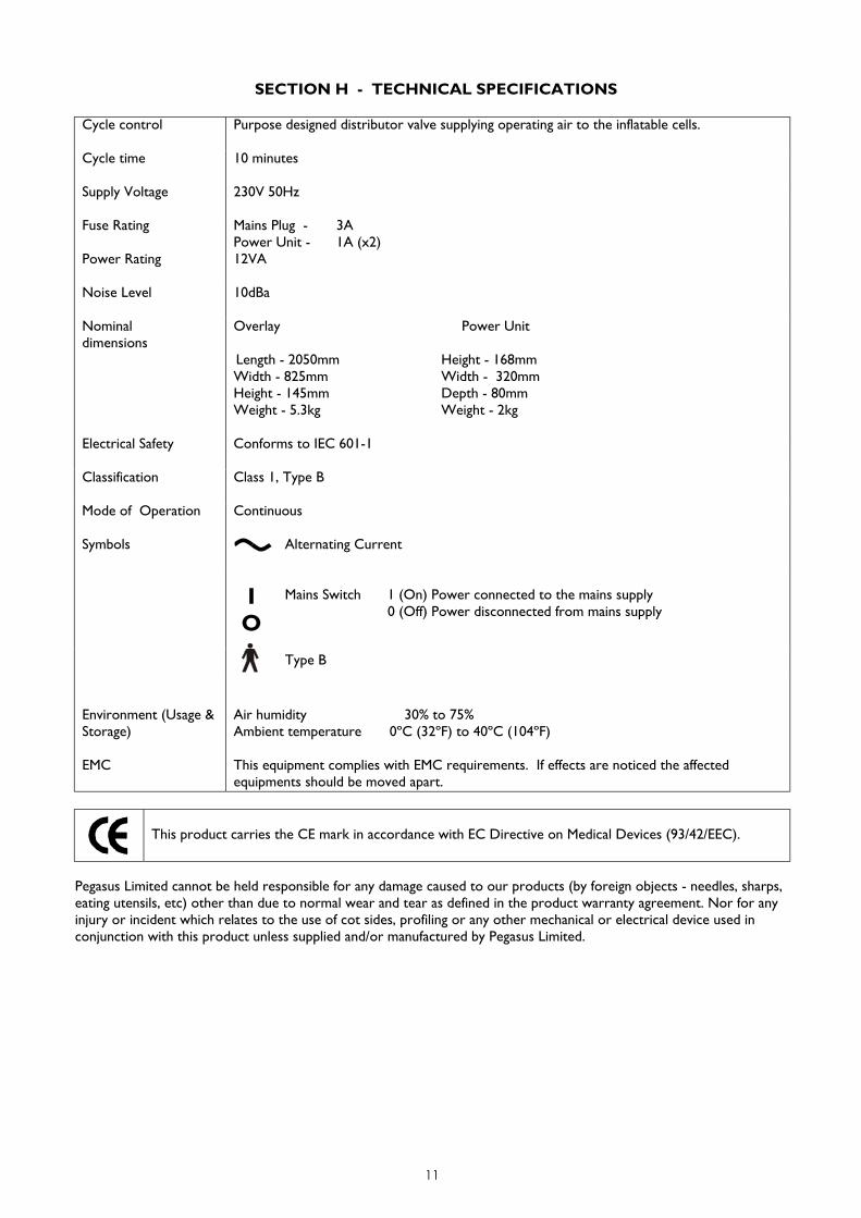
SECTION H - TECHNICAL SPECIFICATIONS
Cycle control Purpose designed distributor valve supplying operating air to the inflatable cells.
Cycle time 10 minutes
Supply Voltage 230V 50Hz
Fuse Rating Mains Plug - 3APower Unit - 1A (x2)
Power Rating 12VA
Noise Level 10dBa
Nominaldimensions
Overlay Power Unit
Length - 2050mm Height - 168mmWidth - 825mm Width - 320mmHeight - 145mm Depth - 80mmWeight - 5.3kg Weight - 2kg
Electrical Safety Conforms to IEC 601-1
Classification Class 1, Type B
Mode of Operation Continuous
Symbols Alternating Current
IO
Mains Switch 1 (On) Power connected to the mains supply0 (Off) Power disconnected from mains supply
Type B
Environment (Usage &Storage)
Air humidity 30% to 75%Ambient temperature 0ºC (32ºF) to 40ºC (104ºF)
EMC This equipment complies with EMC requirements. If effects are noticed the affectedequipments should be moved apart.
This product carries the CE mark in accordance with EC Directive on Medical Devices (93/42/EEC).
Pegasus Limited cannot be held responsible for any damage caused to our products (by foreign objects - needles, sharps,eating utensils, etc) other than due to normal wear and tear as defined in the product warranty agreement. Nor for anyinjury or incident which relates to the use of cot sides, profiling or any other mechanical or electrical device used inconjunction with this product unless supplied and/or manufactured by Pegasus Limited.

LFT11099 Issue 3 © Pegasus Limited 2002
PEGASUS LIMITED
Pegasus House
Waterberry Drive Waterlooville Hampshire
PO7 7XX England
Tel: +44 (0) 23 9278 4200
Fax: +44 (0) 23 9278 4250
E-Mail: [email protected]
Website: www.pegasus-uk.com
PEGASUS,
and the associated device marks are Trademarks of Pegasus Limited.
Pegasus Limited has a policy of continuous product improvement andreserves the right to amend specifications presented in this brochure.
QU
ALI
TY ASSURED
FIR
MISO13485
UKAS
QU
ALIT
YASSURED
FIR
MISO9001
BR
ITIS
H HEALTHCA
RE
TR
AD
ES ASSOCIAT
ION
BHTA