lfenim0002-03(aq)(a4)-lpc iom lps series heavy · pdf file4.2 pneumatic cylinder maintenance...
TRANSCRIPT

USER INSTRUCTIONS
Experience In Motion
Installation Operation
Maintenance
LPC Pneumatic Compact Actuator SeriesSingle Acting & Double ActingFCD LFENIM0002-03-A4 – 08/16

LPC Pneumatic Compact Actuator Series FCD LFENIM0002-03-A4– 08/16
2
Contents1 Standard Information 4Using Flowserve Valves, Actuators and Accessories Correctly 4
1.1 Terms Concerning Safety 41.2 General Usage 51.3 Protective Clothing 51.4 Qualified Personnel 51.5 Other Requirements for In-plant Installation 61.6 Spare Parts 61.7 Service/Repair 61.8 Actuator Lifting and Handling 61.9 Storage 91.10 Valve and Actuator Variations 101.11 Unpacking 10
2 Installation Instructions 112.1 Valve and Actuator Check 112.2 Connection With Valve and Mounting Kit 122.3 Travel-stop Bolts and Accessories 132.4 Grounding System 142.5 Initial Operation 142.6 Fail Open and Fail Close Configuration 15
3 Field Conversion 163.1 Actuator Disassembled From the Valve 16
4 Maintenance Instructions 174.1 General Disassembly Instructions 184.2 Pneumatic Cylinder Maintenance 194.3 Housing and Scotch Yoke Maintenance 214.4 Spare Parts 22
5 Troubleshooting 236 Disposal of Decommissioned Actuators 257 Annex 26
3
LPC Pneumatic Compact Actuator Series FCD LFENIM0002-03-A4– 08/16
flowserve.com
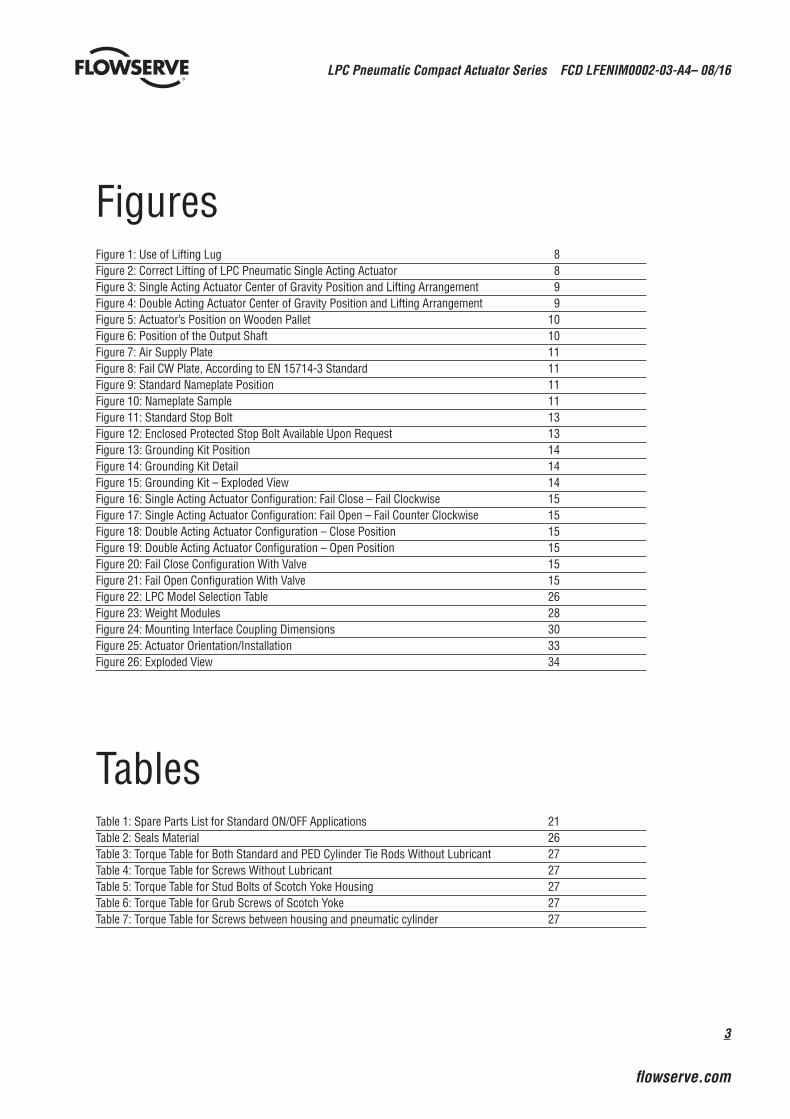
FiguresFigure 1: Use of Lifting Lug 8Figure 2: Correct Lifting of LPC Pneumatic Single Acting Actuator 8Figure 3: Single Acting Actuator Center of Gravity Position and Lifting Arrangement 9Figure 4: Double Acting Actuator Center of Gravity Position and Lifting Arrangement 9Figure 5: Actuator’s Position on Wooden Pallet 10Figure 6: Position of the Output Shaft 10Figure 7: Air Supply Plate 11Figure 8: Fail CW Plate, According to EN 15714-3 Standard 11Figure 9: Standard Nameplate Position 11Figure 10: Nameplate Sample 11Figure 11: Standard Stop Bolt 13Figure 12: Enclosed Protected Stop Bolt Available Upon Request 13Figure 13: Grounding Kit Position 14Figure 14: Grounding Kit Detail 14Figure 15: Grounding Kit – Exploded View 14Figure 16: Single Acting Actuator Configuration: Fail Close – Fail Clockwise 15Figure 17: Single Acting Actuator Configuration: Fail Open – Fail Counter Clockwise 15Figure 18: Double Acting Actuator Configuration – Close Position 15Figure 19: Double Acting Actuator Configuration – Open Position 15Figure 20: Fail Close Configuration With Valve 15Figure 21: Fail Open Configuration With Valve 15Figure 22: LPC Model Selection Table 26Figure 23: Weight Modules 28Figure 24: Mounting Interface Coupling Dimensions 30Figure 25: Actuator Orientation/Installation 33Figure 26: Exploded View 34
TablesTable 1: Spare Parts List for Standard ON/OFF Applications 21Table 2: Seals Material 26Table 3: Torque Table for Both Standard and PED Cylinder Tie Rods Without Lubricant 27Table 4: Torque Table for Screws Without Lubricant 27Table 5: Torque Table for Stud Bolts of Scotch Yoke Housing 27Table 6: Torque Table for Grub Screws of Scotch Yoke 27Table 7: Torque Table for Screws between housing and pneumatic cylinder 27
LPC Pneumatic Compact Actuator Series FCD LFENIM0002-03-A4– 08/16
4
Using Flowserve Valves, Actuators and Accessories Correctly The following instructions are designed to assist in unpacking, installing and performing maintenance as required on the LPC Actuator Series. Product users and maintenance personnel should thoroughly review this bulletin prior to installing, operating or performing any maintenance.
In most cases, Flowserve actuators and accessories are designed for specific applications with regard to medium, pressure and temperature. For this reason they should not be used in other applications without first contacting the manufacturer.
1.1 Terms Concerning SafetyThe safety terms DANGER, WARNING, CAUTION and NOTE are used in these instructions to highlight particular dangers and/or to provide additional information on aspects that may not be readily apparent.
c DANGER: indicates that death, severe personal injury and/or substantial property damage will occur if proper precautions are not taken.
a WARNING: indicates that death, severe personal injury and/or substantial property damage can occur if proper precautions are not taken.
a CAUTION: indicates that minor personal injury and/or property damage can occur if proper precautions are not taken.
NOTE: indicates and provides additional technical information, which may not be very obvious, even to qualified personnel.
Compliance with other, not particularly emphasized notes, with regard to transport, assembly, operation and maintenance and with regard to technical documentation (e.g., in the operating instruction, product documentation or on the product itself) is essential, in order to avoid faults, which in themselves might directly or indirectly cause severe personal injury or property damage.
1 Standard Information

5
LPC Pneumatic Compact Actuator Series FCD LFENIM0002-03-A4– 08/16
flowserve.com
1.2 General Usage To prolong actuator life, use only clean, dry pneumatic supply fluids. Lubricated fluids are not required for LPC actuators. Pay attention to follow positioner and other control prescriptions, regarding supply fluid instrument air.
The LPC actuator standard ambient temperature range is: -29°C to 100°C (-20°F to 212°F). Low temperature -60°C (-76°F) and high temperature 160°C (320°F) ranges (polar, cold, arid and tropical temperature requirements in accordance with IEC 60721) are available with different materials of construction. In any case, please refer to the temperature range field located in the actuator nameplate.
NOTE: For PED applications, the standard operating temperature range is -20°C/+100°C. For lower temperature applications the range can be extended to -40°C to +100°C (-40°F to 212°F) or -50°C to +100°C (-58°F to 212°F) with different materials of construction. In any case, please refer to the temperature range field located in the actuator nameplate.
It is the end user’s responsibility to guarantee that the ambient temperature is in accordance with the actuator nameplate indications.
a WARNING: It is recommended to respect the minimum and maximum allowable temperatures indicated on the actuator nameplate. More factors like the valve and pipe temperatures, sun direct exposure and other environmental conditions shall be considered, not to exceed the temperature range.
a WARNING: It is recommended not to exceed the allowable pressure range of the supply fluids, as stated in the actuator nameplate. It is very important to make the standard maintenance at all safety components. In case of PED cylinders the value of design pressure of the cylinder is indicated on a specific and separate nameplate; it is necessary to verify that the supply line to the actuator does not exceed the design pressure stated in the cylinder nameplate.
NOTE: The standard supply fluids are air and nitrogen. Different types of fluids may be used only after Flowserve verification. In case of PED cylinders the type of fluid is indicated on the specific nameplate on the cylinder.
a WARNING: It is recommended to use the type of fluid indicated on the nameplate (PED cylinders) and/or in the contract.
NOTE: The supply fluid must be properly filtered. In case of positioner and/or other components installed on the control panel, take care that the cleanliness, the filtration and the hydration of the supply fluid are in accordance with the requirements of these accessories indicated on their own maintenance and user manuals.
1.3 Protective ClothingFlowserve products are often used in dangerous applications (e.g., extremely high pressures, flammable, combustible, toxic or corrosive media). When performing service, inspection or repair operations, always ensure that the valve and actuator are depressurized and that the valve has been cleaned and is free from harmful substances. In such cases pay particular attention to personal protection equipment (protective clothing, gloves, glasses, etc.).
1.4 Qualified PersonnelOnly qualified personnel should perform installation, operation or maintenance activities. Qualified personnel are people who, on account of their training, experience, instruction and their knowledge of relevant standards, specifications, accident prevention regulations and operating conditions, have been authorized by those responsible for the safety of the plant to perform the necessary work and who can recognize and avoid possible dangers.
LPC Pneumatic Compact Actuator Series FCD LFENIM0002-03-A4– 08/16
6
1.5 Other Requirements for In-plant Installation• Pipelines must be correctly aligned to ensure that the valve is not fitted under tension.
• If not expressly agreed, fire protection is not supplied along with the actuator and it must be provided by the user.
1.6 Spare PartsUse only Flowserve brand original spare parts. Flowserve cannot accept responsibility for any damages that occur from using spare parts or fastening materials from other manufacturers. If Flowserve products (especially sealing materials) have been in storage for long periods, check for corrosion or deterioration before using these products. A table with the list of the main spare parts for standard ON/OFF applications with the interval times can be found in Paragraph 4.4 in Table 1.
1.7 Service/RepairTo avoid injury to personnel or damage to products, safety terms must be strictly adhered to. Modifying this product, substituting non-factory parts, or using maintenance procedures other than as outlined in this instruction could drastically affect performance and be hazardous to personnel and equipment, and may void existing warranties.
Between actuator and valve there are moving parts. To avoid injury, Flowserve provides pinch-point-protection in the form of cover plates, especially where side-mounted positioners are fitted. These protections are according to Machine Directive 2006/42/EC recommendations. If these plates are removed for inspection, service or repair, special attention is required. After completing work, the cover plates must be refitted.
In addition to the operating instructions and the obligatory accident prevention directives valid in the country of use, all recognized regulations for safety and good engineering practices must be followed.
a WARNING: Before products are returned to Flowserve for repair or service, Flowserve must be provided with a certificate which confirms that the product has been decontaminated and is clean. Flowserve will not accept deliveries if a certificate has not been provided (a form can be obtained from Flowserve).
1.8 Actuator Lifting and Handling Only Allen wrenches and hexagonal wrenches of a few sizes are required for the overall operations. The lifting equipment consists on commercial chains and slings of adequate dimensions.
In order to prevent damage to actuator accessories, before starting the lifting operations, ensure that the lifting tools, like chain and clevis hook, are in the correct position and don’t interfere with the control panel and related tubing.
a CAUTION: Lifting and handling of the actuator should be done by qualified personnel and in compliance with the laws and regulations in force.
a WARNING: The lifting lugs or eyebolts are appropriate for actuator lifting only. They are not designed to support the combined weight of the valve and actuator assembly together. During the lifting operations do not stand under the lifted actuator. The actuator should be handled with appropriate lifting equipment. The weight of the actuator is reported on the packing slip and on the overall-dimensions drawing furnished with the documents accompanying the actuator.

7
LPC Pneumatic Compact Actuator Series FCD LFENIM0002-03-A4– 08/16
flowserve.com
c DANGER: For lifting and handling, use the lifting lugs on the housing and on the tail flange.
Figure 1a: Use of Lifting Lug
Figure 2a: Correct Lifting of LPC-05 and LPC-10 Pneumatic Actuator Models
For actuator weight, please, refer to Figure 23 in the Annex section. For the general actuator dimensions, please refer to LPC technical bulletin LFENTB0002, available on www.flowserve.com.
1.8.1 Lifting Arrangement of LPC-05 and LPC-10 models
a WARNING: ONLY for LPC-05 and LPC-10 models
LPC Pneumatic Compact Actuator Series FCD LFENIM0002-03-A4– 08/16
8
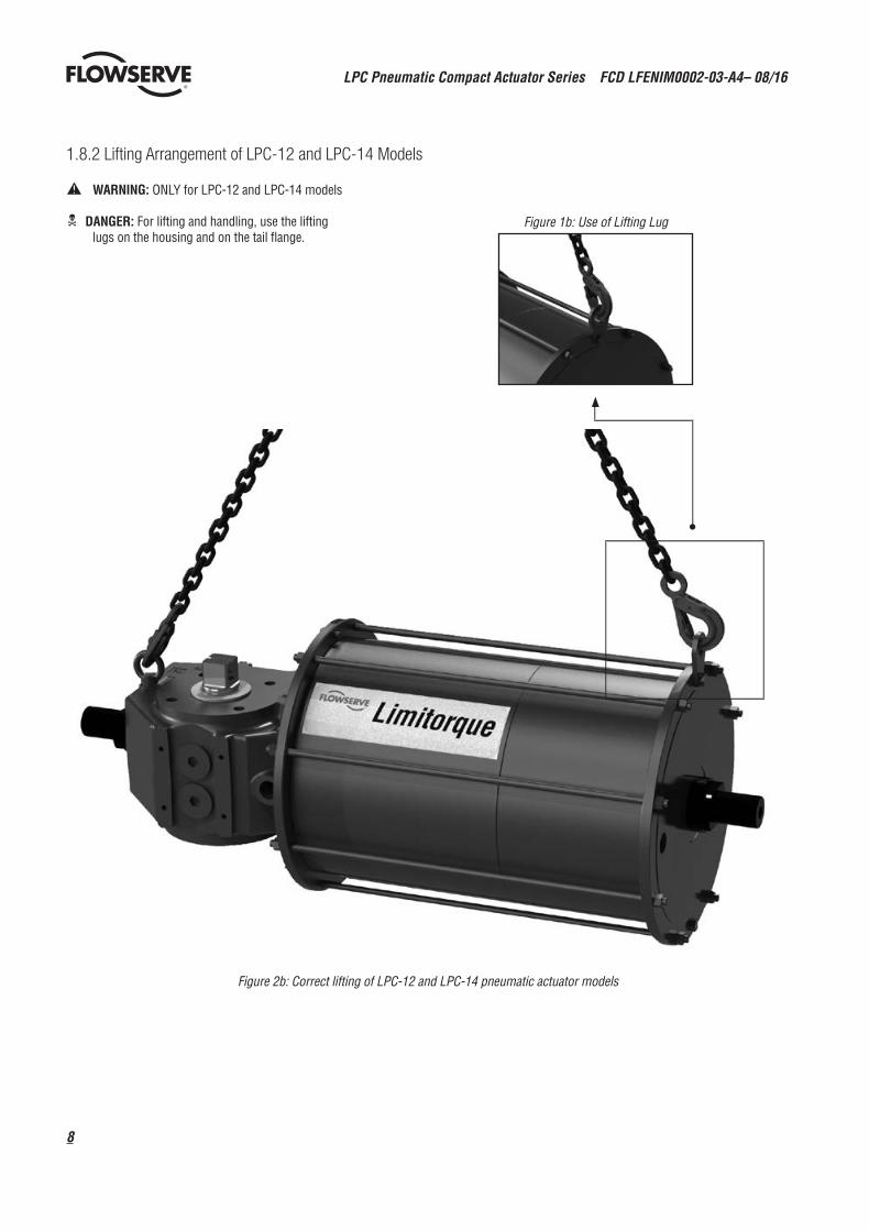
1.8.2 Lifting Arrangement of LPC-12 and LPC-14 Models
a WARNING: ONLY for LPC-12 and LPC-14 models
c DANGER: For lifting and handling, use the lifting lugs on the housing and on the tail flange.
Figure 1b: Use of Lifting Lug
Figure 2b: Correct lifting of LPC-12 and LPC-14 pneumatic actuator models
9
LPC Pneumatic Compact Actuator Series FCD LFENIM0002-03-A4– 08/16
flowserve.com
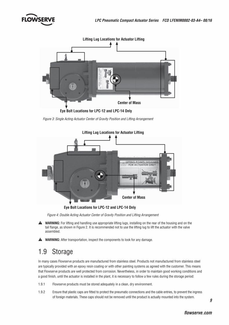
a WARNING: For lifting and handling use appropriate lifting lugs, installing on the rear of the housing and on the tail flange, as shown in Figure 2. It is recommended not to use the lifting lug to lift the actuator with the valve assembled.
a WARNING: After transportation, inspect the components to look for any damage.
1.9 StorageIn many cases Flowserve products are manufactured from stainless steel. Products not manufactured from stainless steel are typically provided with an epoxy resin coating or with other painting systems as agreed with the customer. This means that Flowserve products are well protected from corrosion. Nevertheless, in order to maintain good working conditions and a good finish, until the actuator is installed in the plant, it is necessary to follow a few rules during the storage period:
1.9.1 Flowserve products must be stored adequately in a clean, dry environment.
1.9.2 Ensure that plastic caps are fitted to protect the pneumatic connections and the cable entries, to prevent the ingress of foreign materials. These caps should not be removed until the product is actually mounted into the system.
Eye Bolt Locations for LPC-12 and LPC-14 Only
Center of Mass
Center of Mass
Lifting Lug Locations for Actuator Lifting
Lifting Lug Locations for Actuator Lifting
Figure 3: Single Acting Actuator Center of Gravity Position and Lifting Arrangement
Figure 4: Double Acting Actuator Center of Gravity Position and Lifting Arrangement
Eye Bolt Locations for LPC-12 and LPC-14 Only

LPC Pneumatic Compact Actuator Series FCD LFENIM0002-03-A4– 08/16
10
1.10 Valve and Actuator VariationsThese instructions cannot claim to cover all details of all possible product variations, nor can they provide information for every possible example of installation, operation or maintenance. This means that the instructions normally include only the directions to be followed by qualified personnel where the product is being used for its defined purpose. If there are any uncertainties in this respect, particularly in the event of missing product-related information, clarification must be obtained via the appropriate Flowserve sales office.
1.11 Unpacking1.11.1 Each delivery includes a packing slip. When unpacking, check all delivered actuators and accessories using
this packing slip.
1.11.2 Report transportation damage to the carrier immediately.
1.11.3 In case of discrepancies, contact your nearest Flowserve location.
1.11.4 If necessary, retouch minor damage to the paint coating which may have occurred during transport or storage.
a WARNING:Ensure that the addendum “ATEX/PED/Machinery Directive Manual” accompanies this manual, when the actuator is under one (or more) of the following European Directives:
• 2006/42/EC – Machinery Directive • 94/9/EC – ATEX Directive • 97/23/EC – PED Directive
If “ATEX/PED/Machinery Directive Manual” is not in your hands, contact Flowserve.
NOTE: When the actuator has SIL requirements according to IEC 61508, ensure that the “LPC Series Functional Safety Manual” accompanies this manual and is referred to for equipment usage.
NOTE: Pneumatic cylinder design is based on seismic acceleration of 0.5 g provided as reference by EN 1998-1:2004. It is under User’s responsibility to verify that seismic loads of the geographical installation region of the actuator are in conformity with the reference acceleration value of 0.5 g. For any support please contact your Flowserve Limitorque representative.
Figure 5: Actuator’s Position on Wooden Pallet
Figure 6: Position of the Output Shaft
1.9.3 If the storage is outdoor, or if long-term storage (more than four months) is necessary, the plastic protection plugs have to be replaced by metal plugs, because the plastic plugs have no weatherproof function, whereas the metal ones guarantee a weatherproof protection.
1.9.4 The actuator must be placed on a wooden pallet, in order to not damage the coupling base and avoid the other surfaces resting on the ground.
In case of long-term storage (more than four months), additionally perform the following measures:
a. Coat the coupling parts (spool piece base, flanges, bushings, joints) with protective oil or grease.
b. If possible, blank off the spool piece base flange with a protection disk.
c. Provide a tarpaulin cover or some other means of protection, especially if the storage is outdoors.
d. It is important to periodically operate the actuator with filtered, dehydrated and lubricated air while in storage.
11
LPC Pneumatic Compact Actuator Series FCD LFENIM0002-03-A4– 08/16
flowserve.com
2 Installation Instructions
The LPC range of Limitorque pneumatic actuators is a robust, lightweight modular Scotch yoke design, available in both spring return and double acting configurations. Available with valve interface in compliance with ISO 5211, or customized upon request.
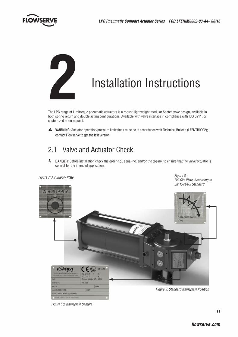
2.1 Valve and Actuator Checkc DANGER: Before installation check the order-no., serial-no. and/or the tag-no. to ensure that the valve/actuator is
correct for the intended application.
a WARNING: Actuator operation/pressure limitations must be in accordance with Technical Bulletin (LFENTB0002); contact Flowserve to get the last version.
Figure 8: Fail CW Plate, According to EN 15714-3 Standard
Figure 9: Standard Nameplate Position
Figure 10: Nameplate Sample
Figure 7: Air Supply Plate
LPC Pneumatic Compact Actuator Series FCD LFENIM0002-03-A4– 08/16
12
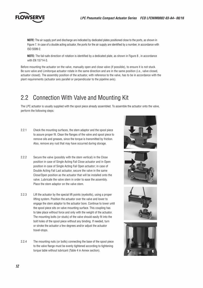
2.2.1 Check the mounting surfaces, the stem adaptor and the spool piece to assure proper fit. Clean the flanges of the valve and spool piece to remove oils and greases, since the torque is transmitted by friction. Also, remove any rust that may have occurred during storage.
2.2.2 Secure the valve (possibly with the stem vertical) in the Close position in case of Single Acting Fail Close actuator and in Open position in case of Single Acting Fail Open actuator; in case of Double Acting Fail Last actuator, secure the valve in the same Close/Open position as the actuator that will be installed onto the valve. Lubricate the valve stem in order to ease the assembly. Place the stem adaptor on the valve stem.
2.2.3 Lift the actuator by the special lift points (eyebolts), using a proper lifting system. Position the actuator over the valve and lower to engage the stem adaptor to the actuator bore. Continue to lower until the spool piece sits on valve mounting surface. This coupling has to take place without force and only with the weight of the actuator. The mounting bolts (or studs) of the valve should easily fit into the bolt holes of the spool piece without any binding. If needed, turn or stroke the actuator a few degrees and/or adjust the actuator travel-stops.
2.2.4 The mounting nuts (or bolts) connecting the base of the spool piece to the valve flange must be evenly tightened according to tightening torque table without lubricant (Table 4 in Annex section).
NOTE: The air supply port and discharge are indicated by dedicated plates positioned close to the ports, as shown in Figure 7. In case of a double acting actuator, the ports for the air supply are identified by a number, in accordance with ISO 5599-2.
NOTE: The fail-safe direction of rotation is identified by a dedicated plate, as shown in Figure 8 , in accordance with EN 15714-3.
Before mounting the actuator on the valve, manually open and close valve (if possible), to ensure it is not stuck. Be sure valve and Limitorque actuator rotate in the same direction and are in the same position (i.e., valve closed, actuator closed). The assembly position of the actuator, with reference to the valve, has to be in accordance with the plant requirements (actuator axis parallel or perpendicular to the pipeline axis).
2.2 Connection With Valve and Mounting KitThe LPC actuator is usually supplied with the spool piece already assembled. To assemble the actuator onto the valve, perform the following steps:

13
LPC Pneumatic Compact Actuator Series FCD LFENIM0002-03-A4– 08/16
flowserve.com
NOTE: In some cases, the coupling between valve and actuator can be direct, without the need of a spool piece. In these cases, Flowserve can provide an intermediate adaptor flange (fitted under the actuator base) and a special bushing to be inserted into the yoke bore.
a WARNING: In case of spool piece (or adapter flange) installation by the client, it is mandatory to refer to the “Mounting Interface Dimensions” paragraph of Technical Bulletin No. LFENTB0002, or to follow more specific instructions included in the job documentation supplied along with the actuator.
a CAUTION: The actuator lifting and handling should be made by qualified personnel and in compliance with the laws and provisions in force.
a WARNING: The lifting lugs or eyebolts are appropriate for actuator lifting only. They are not designed to support the combined weight of the valve and actuator assembly together. During the lifting operations do not stand under the lifted actuator. The actuator should be handled with appropriate lifting means. The weight of the actuator is reported on the packing slip and on the overall-dimensions drawing furnished with the documents accompanying the actuator.
2.3 Travel-stop Bolts and AccessoriesAll actuated valves require accurate travel-stop adjustments at both ends of the stroke to obtain optimum performance and valve seat life. Adjust the travel-stop bolts of the actuator for the proper open and close valve positions, per valve manufacturer’s recommendations.
The LPC actuators have travel-stop adjustments in both the clockwise and counter-clockwise directions. The +/- 5-degree adjustment feature provides shaft rotation from 80 to 100 degrees overall.
The adjustment of the travel-stops is performed in accordance with the following steps. Refer to Figure 26.
• Pneumatic cylinder stop (19): Loosen the hex nut (20) with a proper wrench. Screw or unscrew the stop (19), using a proper Allen key, while keeping the hex nut stationary. Tighten the hex nut.
• Housing stop (19): Loosen the hex nut (20) with a proper wrench. Screw or unscrew the stop (19), using a proper Allen key, while keeping the hex nut stationary. Tighten the hex nut.
Adjust the travel stop bolts of the actuator for the proper open and closed valve positions, per valve manufacturer’s recommendations. Pneumatically stroke the actuator several times to ensure proper operation. If the actuator is equipped with a switch, positioner or other accessories, adjust them at this time.
Limitorque can provide two different solutions of stop bolts as shown in Figures 11 and 12:
Figure 12: Enclosed Protected Stop Bolt Available Upon Request and Suitable for Severe/saline Environmental Conditions
Figure 11: Standard Stop Bolt
LPC Pneumatic Compact Actuator Series FCD LFENIM0002-03-A4– 08/16
14
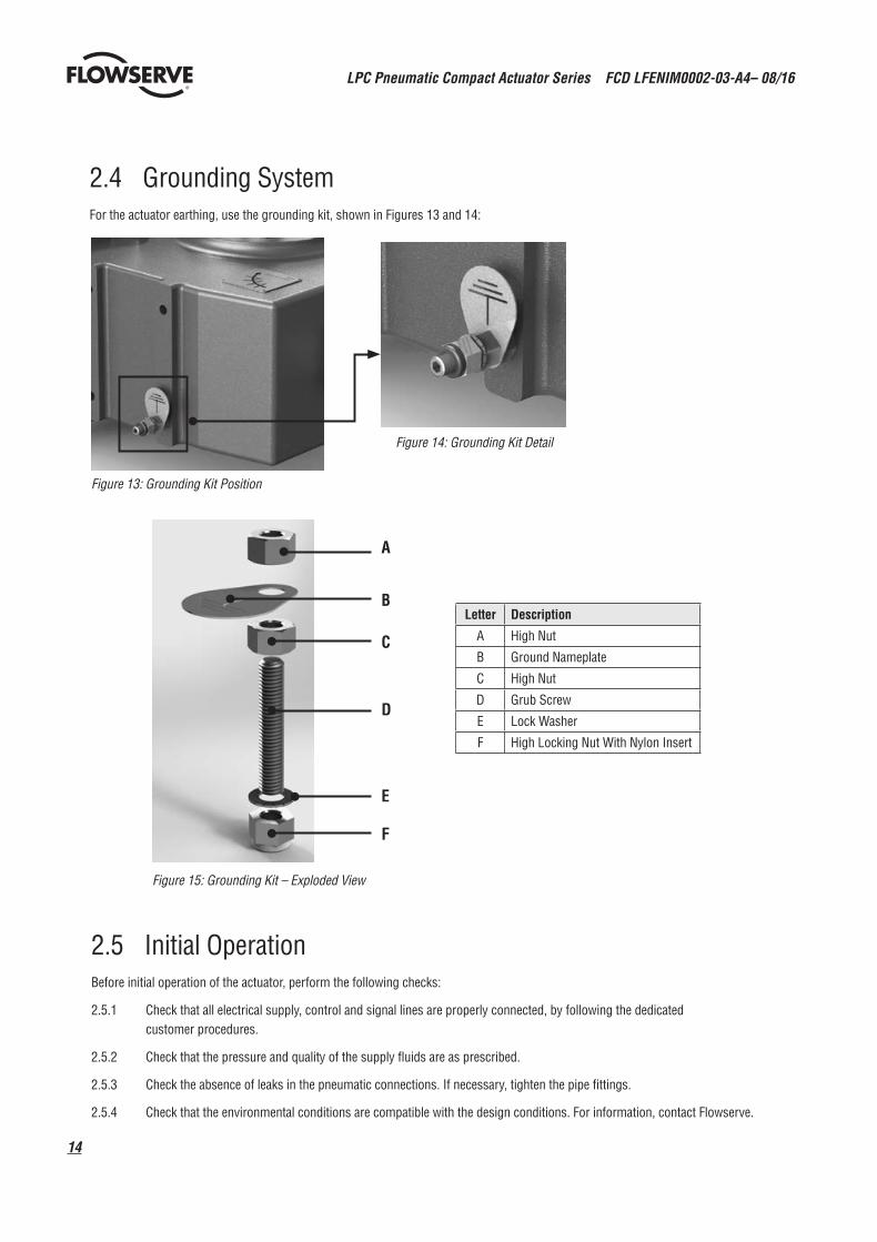
Figure 14: Grounding Kit Detail
Figure 13: Grounding Kit Position
Figure 15: Grounding Kit – Exploded View
Letter Description
A High Nut
B Ground Nameplate
C High Nut
D Grub Screw
E Lock Washer
F High Locking Nut With Nylon Insert
2.4 Grounding SystemFor the actuator earthing, use the grounding kit, shown in Figures 13 and 14:
2.5 Initial OperationBefore initial operation of the actuator, perform the following checks:
2.5.1 Check that all electrical supply, control and signal lines are properly connected, by following the dedicated customer procedures.
2.5.2 Check that the pressure and quality of the supply fluids are as prescribed.
2.5.3 Check the absence of leaks in the pneumatic connections. If necessary, tighten the pipe fittings.
2.5.4 Check that the environmental conditions are compatible with the design conditions. For information, contact Flowserve.
A
B
C
D
E
F

15
LPC Pneumatic Compact Actuator Series FCD LFENIM0002-03-A4– 08/16
flowserve.com
2.6 Fail Open and Fail Close Configuration The actuator is designed for work in both configurations: fail open and fail close. For conversion from one configuration to the other, refer to next paragraph.
Figure 16: Single Acting Actuator Configuration: Fail Close – Fail Clockwise
Figure 17: Single Acting Actuator Configuration: Fail Open – Fail Counter Clockwise
Figure 20: Fail Close Configuration With Valve
Figure 21: Fail Open Configuration With Valve
Figure 18: Double Acting Actuator Configuration – Close Position Figure 19: Double Acting Actuator Configuration – Open Position
LPC Pneumatic Compact Actuator Series FCD LFENIM0002-03-A4– 08/16
16
3 Field Conversion
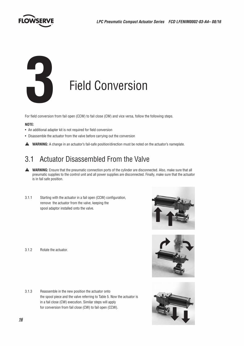
For field conversion from fail open (CCW) to fail close (CW) and vice versa, follow the following steps.
NOTE:• An additional adapter kit is not required for field conversion
• Disassemble the actuator from the valve before carrying out the conversion
a WARNING: A change in an actuator’s fail-safe position/direction must be noted on the actuator’s nameplate.
3.1 Actuator Disassembled From the Valve a WARNING: Ensure that the pneumatic connection ports of the cylinder are disconnected. Also, make sure that all
pneumatic supplies to the control unit and all power supplies are disconnected. Finally, make sure that the actuator is in fail safe position.
3.1.1 Starting with the actuator in a fail open (CCW) configuration, remove the actuator from the valve, keeping the spool adaptor installed onto the valve.
3.1.2 Rotate the actuator.
3.1.3 Reassemble in the new position the actuator onto the spool piece and the valve referring to Table 5. Now the actuator is in a fail close (CW) execution. Similar steps will apply for conversion from fail close (CW) to fail open (CCW).
17
LPC Pneumatic Compact Actuator Series FCD LFENIM0002-03-A4– 08/16
flowserve.com
4 Maintenance Instructions
LPC Series actuators are designed to offer the greatest ease of operation during assembly, disassembly and maintenance. The maintenance and disassembly do not require special equipment or special or large wrenches. Furthermore, the joints among the moving parts of the actuator are made exclusively through pins and not using bolts to be tightened with specific torques.
LPC actuators do not need maintenance for long periods, even if they are working in severe conditions. The LPC actuator features a 25-year design life depending on service conditions, proper installation, operating and maintenance. In order to achieve this industry-leading design life, in-field maintenance is prescribed to be performed every five years of operations.
However, if actuator operation happens infrequently, it is recommended to periodically check the actuator, performing the following steps:
• In the plants where it is possible, carry out a few opening and closing operations, involving all the control unit components, checking that the actuator operates correctly and within the required stroking times.
• Check that all the signals (pneumatic and electric) arrive correctly to the actuator and that the supply fluid pressure is within the required range. Check for the absence of leaks in the pneumatic connections. If necessary, tighten the pipe fittings.
• Check the paint coating. If some areas are damaged due to accidental events, retouch them according to the painting specifications.
In case of scheduled preventive maintenance, or following accidental events, refer to the following maintenance instructions regarding the main actuator components (pneumatic cylinder and housing).
NOTE: In the LPC compact actuator series, in single acting execution, it is not possible to perform spring can maintenance, since the spring is located inside the pneumatic cylinder; the periodic service operations are possible only on the housing and on the pneumatic cylinder. For any issue related to spring can, it is essential to replace the entire spring and cylinder assembly.
The following instructions are referred to both standard maintenance inside Scotch yoke housing and to the entire spring and cylinder assembly replacement. The reference drawings for the instructions reported in the following paragraphs are exploded views of single acting and double acting actuators, included as Figure 26.
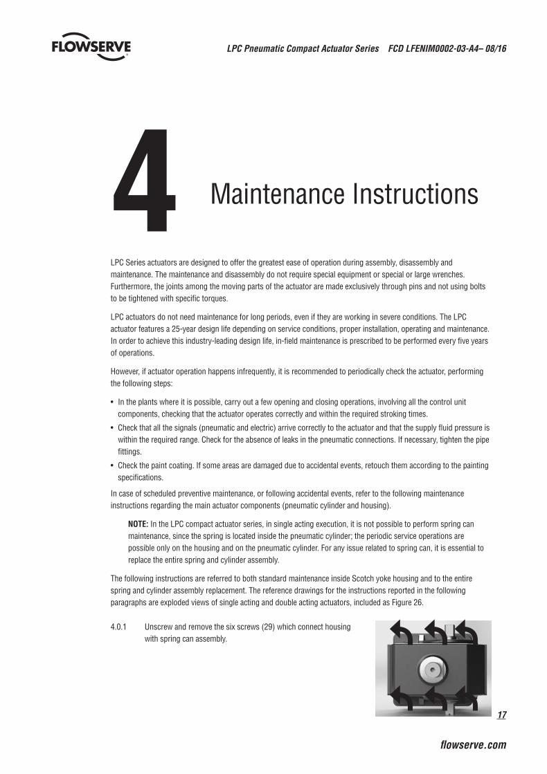
4.0.1 Unscrew and remove the six screws (29) which connect housing with spring can assembly.
LPC Pneumatic Compact Actuator Series FCD LFENIM0002-03-A4– 08/16
18
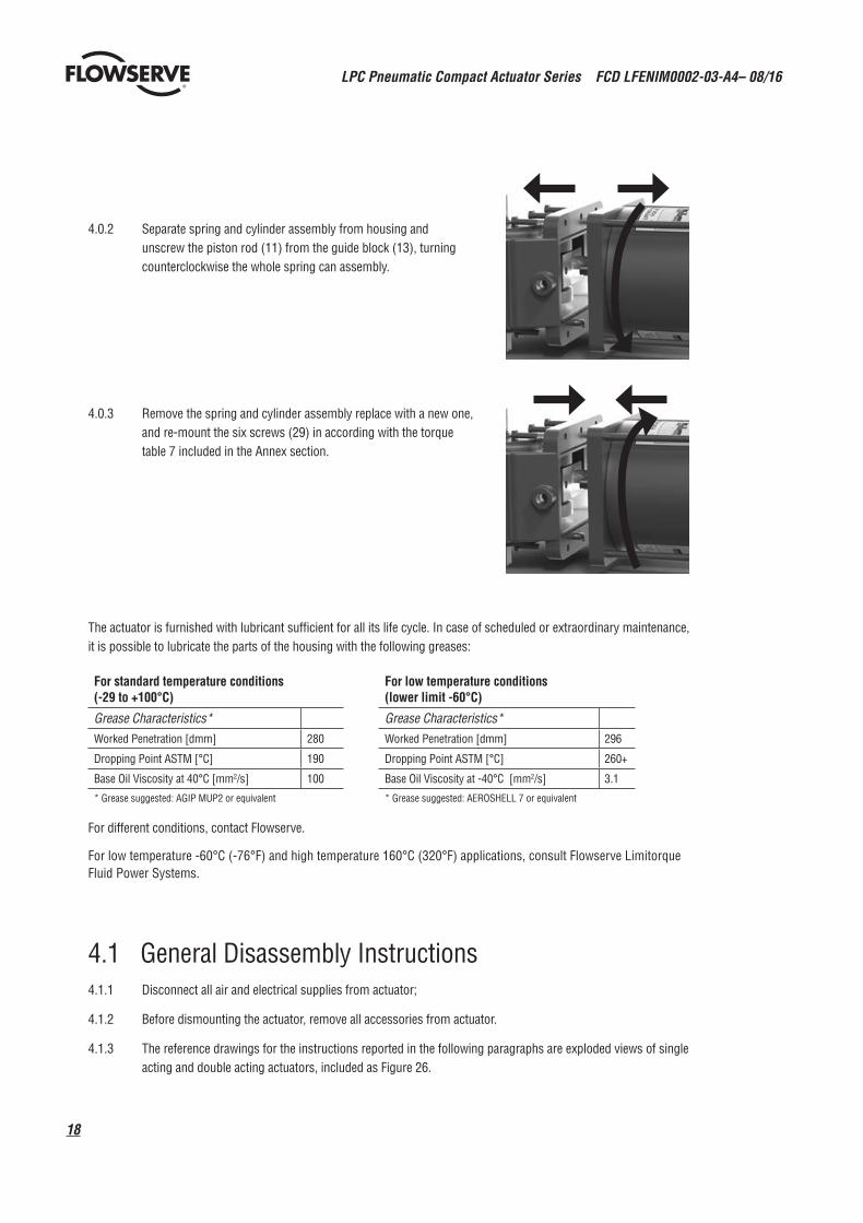
4.0.2 Separate spring and cylinder assembly from housing and unscrew the piston rod (11) from the guide block (13), turning counterclockwise the whole spring can assembly.
4.0.3 Remove the spring and cylinder assembly replace with a new one, and re-mount the six screws (29) in according with the torque table 7 included in the Annex section.
The actuator is furnished with lubricant sufficient for all its life cycle. In case of scheduled or extraordinary maintenance, it is possible to lubricate the parts of the housing with the following greases:
For different conditions, contact Flowserve.
For low temperature -60°C (-76°F) and high temperature 160°C (320°F) applications, consult Flowserve Limitorque Fluid Power Systems.
4.1 General Disassembly Instructions4.1.1 Disconnect all air and electrical supplies from actuator;
4.1.2 Before dismounting the actuator, remove all accessories from actuator.
4.1.3 The reference drawings for the instructions reported in the following paragraphs are exploded views of single acting and double acting actuators, included as Figure 26.
For standard temperature conditions (-29 to +100°C)
For low temperature conditions (lower limit -60°C)
Grease Characteristics* Grease Characteristics* Worked Penetration [dmm] 280 Worked Penetration [dmm] 296
Dropping Point ASTM [°C] 190 Dropping Point ASTM [°C] 260+
Base Oil Viscosity at 40°C [mm2/s] 100 Base Oil Viscosity at -40°C [mm2/s] 3.1
* Grease suggested: AGIP MUP2 or equivalent * Grease suggested: AEROSHELL 7 or equivalent

19
LPC Pneumatic Compact Actuator Series FCD LFENIM0002-03-A4– 08/16
flowserve.com
4.2 Pneumatic Cylinder MaintenanceThe standard pneumatic cylinder maintenance mainly consists in the replacement of all parts that may degrade in the course of time, even in the absence of faults. These components are the O-rings and the sliding elements of the piston. The substitution of cylinder components (or of the whole cylinder) is not expected over the entire actuator life. However, accidental events may result in damage to these components. In these cases, proceed as described in the following steps.
There are two possible types of maintenance: standard maintenance which can be performed in the field without the need to remove the pneumatic cylinder from the actuator, and a more thorough maintenance, following unexpected events, which often can be performed only after removing the cylinder from the actuator.
c DANGER: It’s recommended to not accomplish this maintenance operation with cylinder under pressure.
Standard In-field Maintenance
a WARNING: Before performing any maintenance operation on cylinder it’s mandatory to remove the pressure inside the cylinder itself. Make sure that the pneumatic connection ports of the cylinder are disconnected and open to the ambient. Also make sure that all pneumatic supplies to the control unit and all power supplies are discon-nected. Make sure that the actuator is in fail safe position, i.e., that it is not locked in a position with the spring compressed by means of locking devices.
a WARNING: Use the pneumatic cylinder only for the intended function it has been designed for.
NOTE: During the maintenance operation inside the cylinder it’s suggested to have a visual check of the internal parts of the cylinder in order to guarantee their integrity.
NOTE: In the LPC Compact Actuator Series, in single acting execution, the spring is located inside the pneumatic cylinder, as shown in Figures 16 and 17.
Perform the following steps with reference to Figure 26.
4.2.1 Unscrew and remove the travel stop of the pneumatic cylinder (19). For removing the stop, refer to the indications given in paragraph 2.3.
4.2.2 Remove four tie rods (16) positioned on the cylinder by unscrewing the nuts (18) on the sides of the End Flange and unscrewing the tie rods from the adaptor flange (26).
LPC Pneumatic Compact Actuator Series FCD LFENIM0002-03-A4– 08/16
20
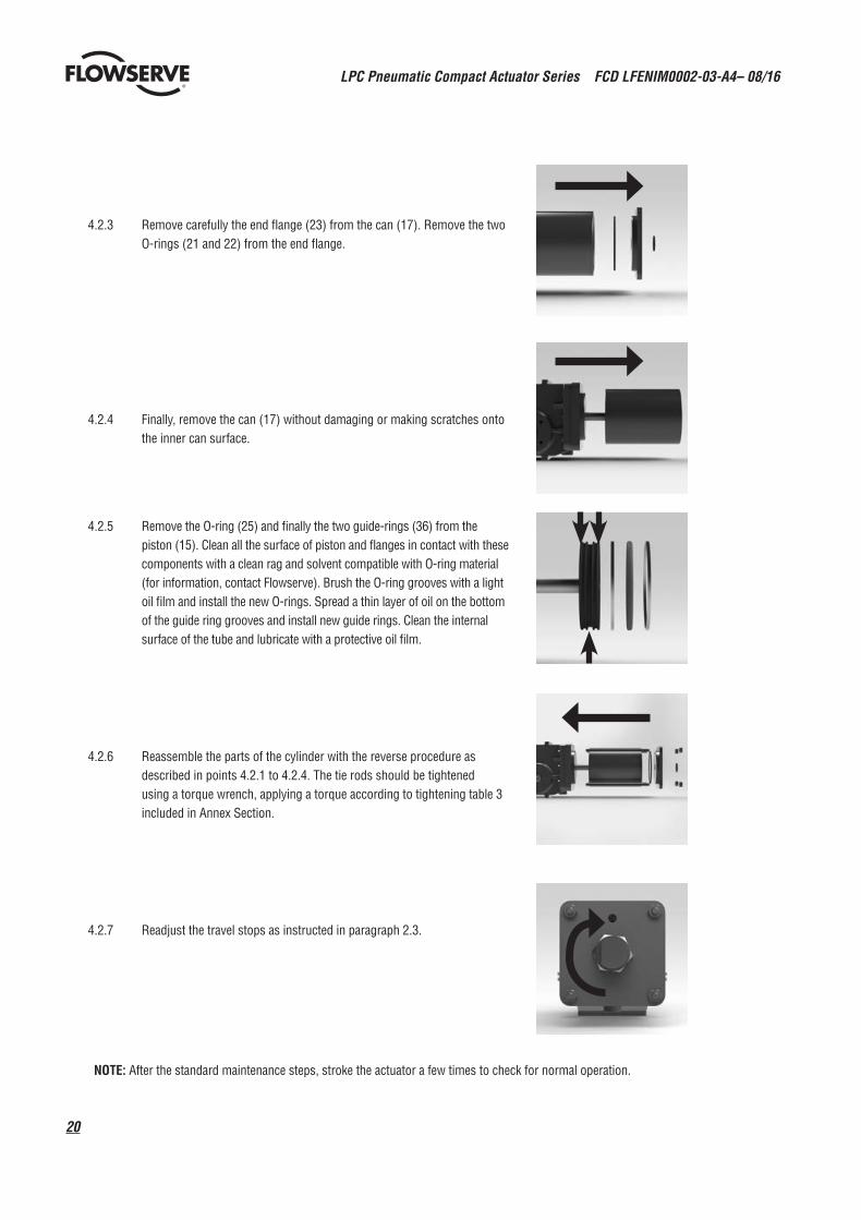
4.2.3 Remove carefully the end flange (23) from the can (17). Remove the two O-rings (21 and 22) from the end flange.
4.2.4 Finally, remove the can (17) without damaging or making scratches onto the inner can surface.
4.2.5 Remove the O-ring (25) and finally the two guide-rings (36) from the piston (15). Clean all the surface of piston and flanges in contact with these components with a clean rag and solvent compatible with O-ring material (for information, contact Flowserve). Brush the O-ring grooves with a light oil film and install the new O-rings. Spread a thin layer of oil on the bottom of the guide ring grooves and install new guide rings. Clean the internal surface of the tube and lubricate with a protective oil film.
4.2.6 Reassemble the parts of the cylinder with the reverse procedure as described in points 4.2.1 to 4.2.4. The tie rods should be tightened using a torque wrench, applying a torque according to tightening table 3 included in Annex Section.
4.2.7 Readjust the travel stops as instructed in paragraph 2.3.
NOTE: After the standard maintenance steps, stroke the actuator a few times to check for normal operation.

21
LPC Pneumatic Compact Actuator Series FCD LFENIM0002-03-A4– 08/16
flowserve.com
4.3 Housing and Scotch Yoke MaintenanceStandard maintenance of the housing may take place in the field.
a WARNING: Ensure that the pneumatic connection ports of the cylinder are disconnected. Also make sure that all pneumatic supplies to the control unit and all power supplies are disconnected. Finally, make sure that the actuator is in the fail-safe position.
a WARNING: In LPC Double Acting version, the actuator is fed using two pneumatic inlet ports, one located on the cylinder end flange and the other one located on the Scotch yoke housing. It’s recommended to accomplish this maintenance operation only after removing the supply pressure from the Scotch yoke housing inlet port.
Standard In-field MaintenanceUnscrew the housing stop bolt (19) and apply a film of grease (with an applicator) directly on the Scotch yoke’s sliding surface.
NOTE: Take note of the length of the stop bolt before making the standard maintenance and reassemble it at the same length.
Special MaintenanceIf it is necessary to carry out extra maintenance inside the housing, perform the following steps.
4.3.1 Remove the actuator from the valve.
4.3.2 Remove the pneumatic cylinder, unscrewing the six screws (29) and unbolting the piston rod (11) to the guide block (13).
4.3.3 Remove the guide bar (10). Remove the O-ring (9).
LPC Pneumatic Compact Actuator Series FCD LFENIM0002-03-A4– 08/16
22
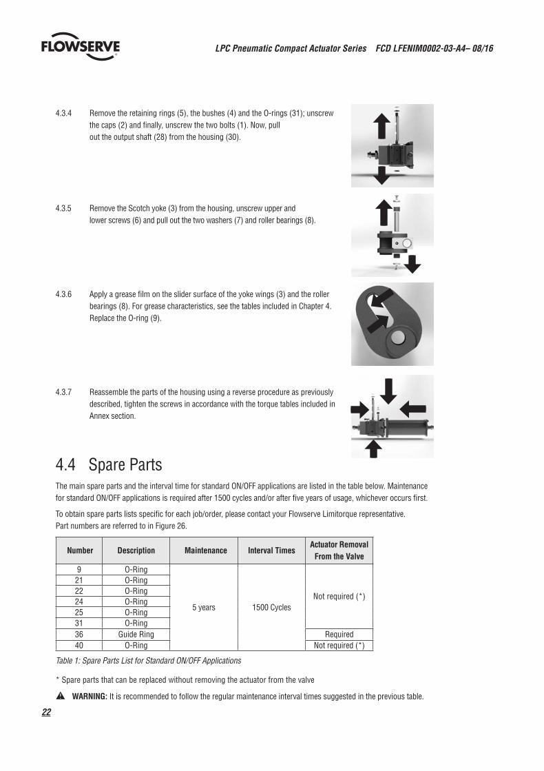
4.4 Spare Parts The main spare parts and the interval time for standard ON/OFF applications are listed in the table below. Maintenance for standard ON/OFF applications is required after 1500 cycles and/or after five years of usage, whichever occurs first.
To obtain spare parts lists specific for each job/order, please contact your Flowserve Limitorque representative. Part numbers are referred to in Figure 26.
Number Description Maintenance Interval Times Actuator Removal
From the Valve
9 O-Ring
5 years 1500 CyclesNot required (*)
21 O-Ring22 O-Ring24 O-Ring25 O-Ring31 O-Ring36 Guide Ring Required40 O-Ring Not required (*)
Table 1: Spare Parts List for Standard ON/OFF Applications
* Spare parts that can be replaced without removing the actuator from the valve
a WARNING: It is recommended to follow the regular maintenance interval times suggested in the previous table.
4.3.4 Remove the retaining rings (5), the bushes (4) and the O-rings (31); unscrew the caps (2) and finally, unscrew the two bolts (1). Now, pull out the output shaft (28) from the housing (30).
4.3.5 Remove the Scotch yoke (3) from the housing, unscrew upper and lower screws (6) and pull out the two washers (7) and roller bearings (8).
4.3.6 Apply a grease film on the slider surface of the yoke wings (3) and the roller bearings (8). For grease characteristics, see the tables included in Chapter 4. Replace the O-ring (9).
4.3.7 Reassemble the parts of the housing using a reverse procedure as previously described, tighten the screws in accordance with the torque tables included in Annex section.
23
LPC Pneumatic Compact Actuator Series FCD LFENIM0002-03-A4– 08/16
flowserve.com
5 Troubleshooting
To prevent the actuator from not functioning properly or a reduction in performance, first ensure that the installation and the adjustment operations are carried out completely in accordance with this manual.
a WARNING: When attempting to identify faults, it is very important to observe all the regulations and instructions about safety. Read all the paragraphs of this manual concerning maintenance before opening for inspection or starting to repair any actuator components. If in doubt, choose SAFETY FIRST.
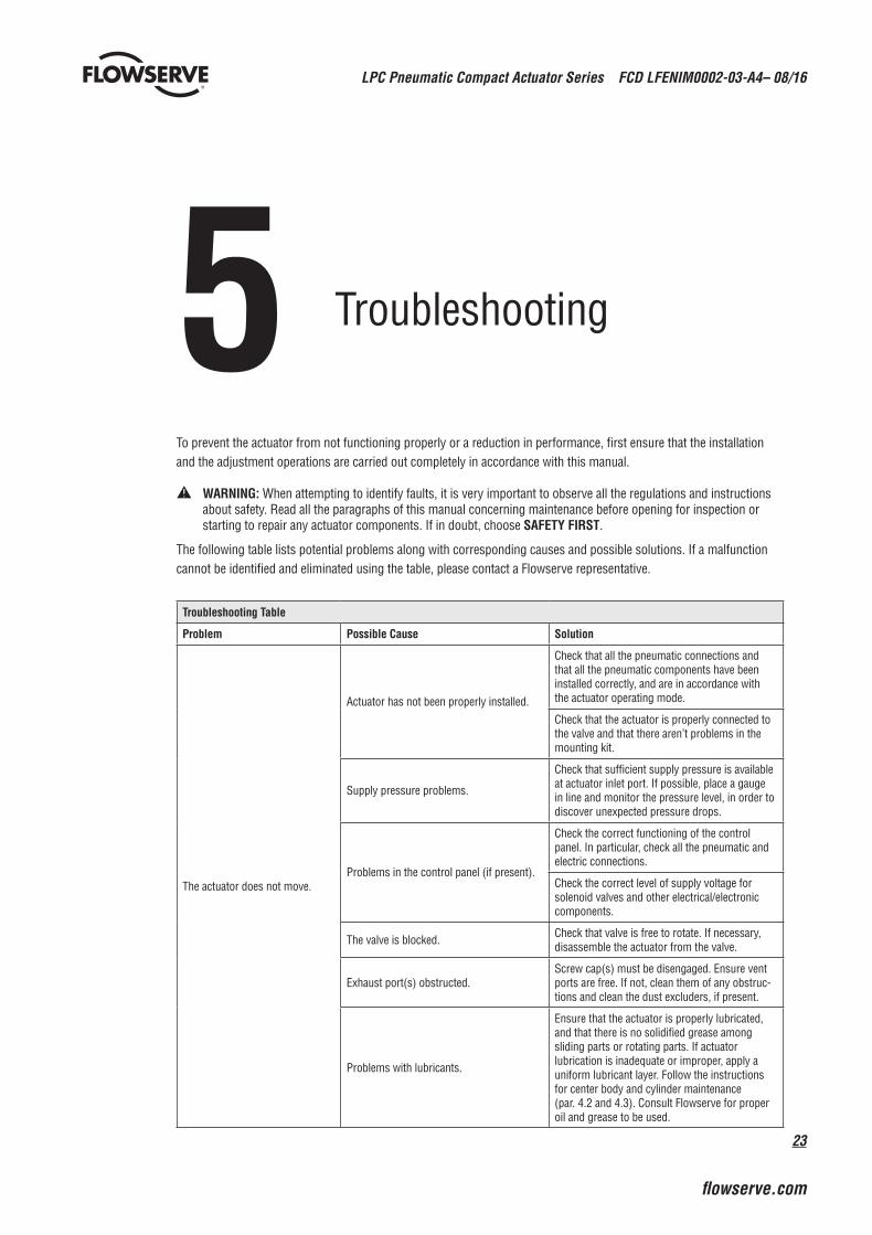
The following table lists potential problems along with corresponding causes and possible solutions. If a malfunction cannot be identified and eliminated using the table, please contact a Flowserve representative.
Troubleshooting Table
Problem Possible Cause Solution
The actuator does not move.
Actuator has not been properly installed.
Check that all the pneumatic connections and that all the pneumatic components have been installed correctly, and are in accordance with the actuator operating mode.
Check that the actuator is properly connected to the valve and that there aren’t problems in the mounting kit.
Supply pressure problems.
Check that sufficient supply pressure is available at actuator inlet port. If possible, place a gauge in line and monitor the pressure level, in order to discover unexpected pressure drops.
Problems in the control panel (if present).
Check the correct functioning of the control panel. In particular, check all the pneumatic and electric connections.
Check the correct level of supply voltage for solenoid valves and other electrical/electronic components.
The valve is blocked. Check that valve is free to rotate. If necessary, disassemble the actuator from the valve.
Exhaust port(s) obstructed.Screw cap(s) must be disengaged. Ensure vent ports are free. If not, clean them of any obstruc-tions and clean the dust excluders, if present.
Problems with lubricants.
Ensure that the actuator is properly lubricated, and that there is no solidified grease among sliding parts or rotating parts. If actuator lubrication is inadequate or improper, apply a uniform lubricant layer. Follow the instructions for center body and cylinder maintenance (par. 4.2 and 4.3). Consult Flowserve for proper oil and grease to be used.

LPC Pneumatic Compact Actuator Series FCD LFENIM0002-03-A4– 08/16
24
Troubleshooting Table
Problem Possible Cause Solution
The actuator does not move.
A moving part is seized up.
Check if any moving part is blocked. If so, follow the maintenance instructions given in the relevant paragraphs of this manual or in special mainte-nance operating instructions in paragraph 4.3.
Leakages of the pneumatic cylinder.
A significant air leak may prevent the actuator from operating. Ensure that there aren’t any leaks of the pneumatic cylinder. If possible, detect them using a leak finder spray. Check also that there are not leaks across the piston. If leaks are present, follow the cylinder maintenance instructions given in paragraph 4.2.
The actuator model is not the correct one, or is not suitable for the plant conditions.
Check the actuator nameplate and the plant requirements. If there are mismatches, contact Flowserve Service Department.
Spring problems (if actuator is a single acting model).
Check the proper functioning of the spring can. If problems are found, contact the Flowserve Service Department.
Perform the following test: disassemble the actuator from the valve and measure the minimum pressure values necessary to move and compress the spring. Compare the measured values with the ones reported on the Testing Certificate. If there are significant differences you should contact Flowserve Service Department.
A lockout device has been inserted and forgotten in that position. Disconnect the lockout module.
The valve does not shut off properly and there are leaks. The actuator is not correctly adjusted.
Adjust the end stops of the pneumatic cylinder and of the spring can until the valve is leak-tight across the seat. Follow the instructions given in the paragraph about Travel-stop bolts (2.3).
The valve does not fully perform the stroke, during opening or closing.
The actuator is not correctly adjusted.
As above, check the position of the end stop in opening and closing direction. If necessary, adjust them. Follow the instructions given in paragraph 2.3.
Exhaust port(s) obstructed.Screw cap(s) must be disengaged. Ensure vent ports are free. If not, clean them of any obstruc-tions and clean the dust excluders, if present.
Actuator torque lower than required.
In order to do a check it is necessary to perform the following test: disassemble the actuator from the valve and measure the minimum pressure values necessary to move and compress the spring (if the actuator is a single acting model) or the minimum values necessary to move the actuator yoke and perform a stroke (for double acting models). Compare the measured values with the ones reported on the Testing Certificate. If there are significant differences you should contact Flowserve Service Department.
During the stroke the actuator exhibits excessive amounts of backlash.
Some components are excessively worn.Identify and replace these components, according to the procedure described in paragraphs 4.2 and 4.3.
In case of other problems not listed in this table, you should contact the Flowserve Service Department.

25
LPC Pneumatic Compact Actuator Series FCD LFENIM0002-03-A4– 08/16
flowserve.com
6 Disposal of Decommissioned Actuatorsa WARNING: Before disassembling the actuator from the valve and before any decommissioning activity ensure that
the pneumatic connection ports of the cylinder are disconnected and open to the ambient. Also make sure that power and pneumatic supplies are turned off, and bleed any pressurized parts of the actuator, control panel and pneumatic tubing (including air tanks, if present). Verify that the actuator is in fail safe position, i.e., that it is not locked in a position with the spring compressed by means of locking devices.
Spring Return Actuators that are to be decommissioned permanently must have the stored energy in the spring neutral-ized. For LPC and LPS actuators, the spring module can be safely disassembled from the actuator if the supply pressure has been removed and the actuator is in its fail safe position: in fact, in this condition, any residual spring preload is not transmitted to the actuator. To disassemble the spring module from the actuator follow the instructions provided at Paragraph 4.1 of this manual.
Once the Spring Module is disassembled from the actuator, the spring inside the spring module can be neutralized in different ways depending on the equipment available on site. Please contact your Flowserve Limitorque representative to receive a dedicated procedure for Spring Module disassembly, in order to safely perform this operation in the most appropriate way according to available equipment and tools.
a WARNING: Failure to neutralize the spring contained in the actuator’s spring module or to follow these instruc-tions could lead to injury to personnel or property damage.
No other specific actions need be taken on other portions/parts of the actuator for decommissioning. To disassemble pneumatic cylinder and scotch-yoke housing, follow the instructions provided respectively at Paragraph 4.2 and 4.3 of this manual.
All disassembled parts of the actuator shall be separated according to their material type (metal, rubber, plastic, oil and grease, electric and electronic equipment ...). Dispose them with support of differentiated waste collection sites, as provided for by the laws and provisions in force.
LPC Pneumatic Compact Actuator Series FCD LFENIM0002-03-A4– 08/16
26
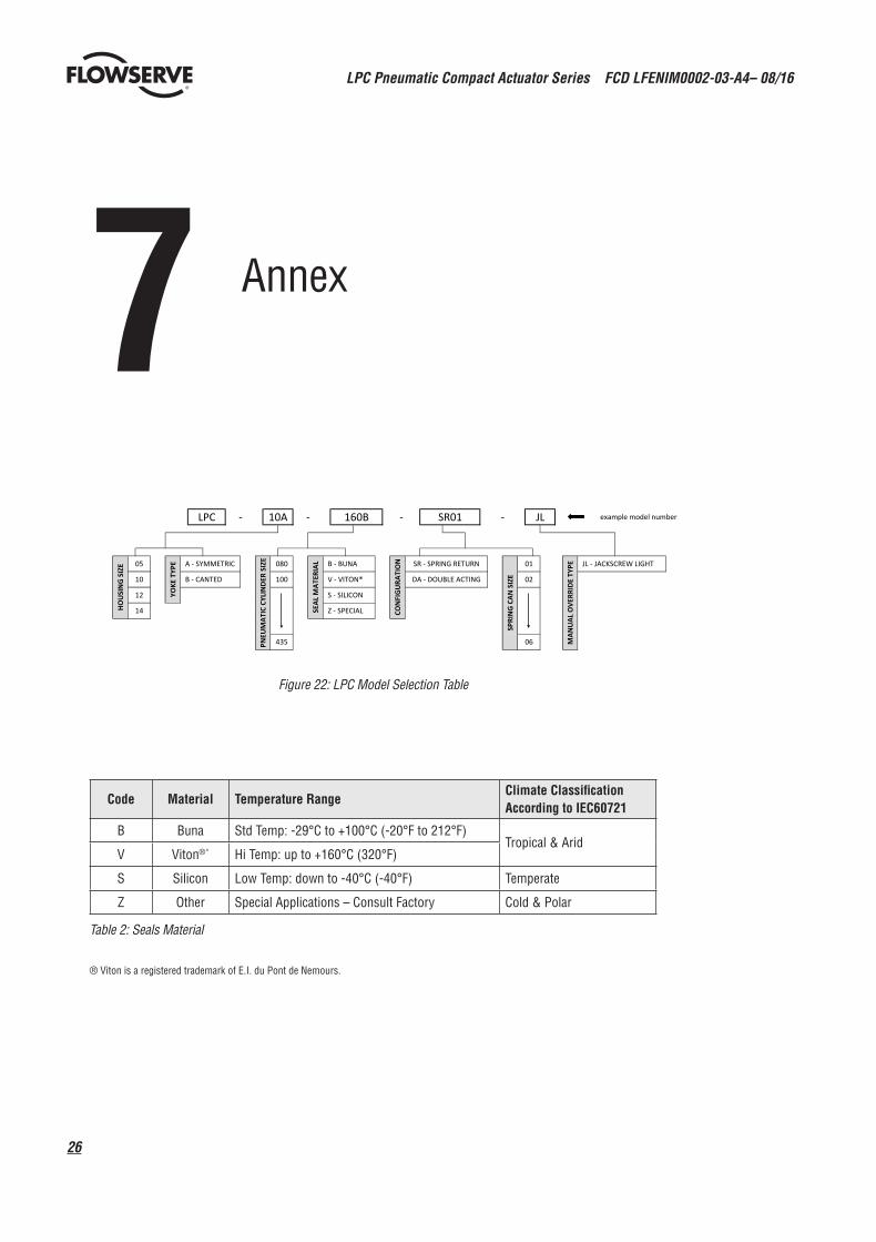
Figure 22: LPC Model Selection Table
Table 2: Seals Material
7 Annex
HO
USI
NG
SIZ
E SR - SPRING RETURN
CON
FIG
URA
TIO
N
SPRI
NG
CAN
SIZ
E
05
YOKE
TYP
E A - SYMMETRIC
B - CANTED10
12
14
100 DA - DOUBLE ACTING
06 MAN
UAL
OVE
RRID
E TY
PE
PNEU
MAT
IC C
YLIN
DER
SIZE
example model number
01
02
- JL
JL - JACKSCREW LIGHT
S - SILICON
Z - SPECIALSEAL
MAT
ERIA
L B - BUNA
V - VITON®
435
080
LPC - 10A SR01- 160B -
Code Material Temperature RangeClimate Classification According to IEC60721
B Buna Std Temp: -29°C to +100°C (-20°F to 212°F)Tropical & Arid
V Viton®* Hi Temp: up to +160°C (320°F)
S Silicon Low Temp: down to -40°C (-40°F) Temperate
Z Other Special Applications – Consult Factory Cold & Polar
® Viton is a registered trademark of E.I. du Pont de Nemours.

27
LPC Pneumatic Compact Actuator Series FCD LFENIM0002-03-A4– 08/16
flowserve.com
SCREW DIAMETER Torque [Nm]
M3 0,8
M4 1,9
M5 3,8
M6 6,6
M8 16
M10 32
M12 54
M14 88
M16 136
M18 189
M20 268
M22 369
M24 461
M27 683
M30 926
M33 1257
M36 1614
M39 2095
M42 2586
M45 3237
M48 3910
M52 5034
M56 6270
M60 7790
M64 9373
Table 4: Torque Table for Screws without Lubricant applicable also to Mounting Kit – Exclusions: Tie Rods (see Table 3), Stud Bolts screwed into scotch yoke housing (see Table 5); Grub Screws of Scotch Yoke (see Table 6); Screws between housing and Pneumatic Cylinder (see Table 7)
TIE RODS DIAMETER TORQUE [Nm]
4xM10 20
4xM12 45
8xM12 60
8xM16 110
Actuator Model
Stud Bolts Diameter
Torque [Nm]
LPC-05 M8 16
LPC-10 M12 55
LPC-12 M16 136
LPC-14 M20 268
Actuator Model
Grub Screw Diameter
Torque [Nm]
LPC-05 M20 268
LPC-10 M30 926
LPC-12 M36 775
LPC-14 M42 1241
Table 3: Torque Table for both Standard and PED cylinder tie rods without lubricant (Num. 16, 18 with reference to Figure 26)
Table 5: Torque Table for stud bolts of scotch-yoke housing coupling interface.
IMPORTANT: During studs assembly use Loctite 542 or equivalent.
Table 6: Torque Table for Grub Screws of Scotch Yoke (Num. 1 with reference to Figure 26).
IMPORTANT: During grub screw assembly use Loctite 270 or equivalent.
Screw Diameter
Torque [Nm]
M8 21
M10 42
M12 72
M14 116
Table 7: Torque Table for Screws between housing and pneumatic cylinder (Num. 29 with reference to Figure 26)

LPC Pneumatic Compact Actuator Series FCD LFENIM0002-03-A4– 08/16
28
-080Y SR02
Ø CYLINDER
WEIGHT TABLE - SINGLE ACTING (Fail Close/Fail Open Actuators)
LPC - 05X - 080Y - SR01
LPC - 14SPRING LPC - 05 LPC - 10 LPC - 12
100Y SR02 21 (46) - -
080Y SR01 17 (38) - -
-
18 (39) - - -100Y SR01 21 (46) 32 (70) - -
120Y SR01 24 (53) 35 (77) - -100Y SR03 21 (46) - - -
HO
USI
NG
SIZ
E
LPC - 05 21 (45)
120Y SR02 24 (53)120Y SR03 24 (54)120Y SR04 26 (56)120Y SR05 26 (57)
140Y SR02 28 (62)LPC - 10 29 (64)
140Y SR01 28 (61)
140Y
37 (82) - -
END
STO
PS K
IT (*
)
LPC - 05 1,5 (3,4)- - -
-- - -- -
LPC - 10 2,6 (5,6)40 (89) - -38 (85) 45 (99) -
LPC - 12-
160Y SR02 33 (73) 50 (110) 51 (113) -
SR03 28 (62) 44 (98) - -140Y SR04 29 (65) - - -
LPC - 12 53 (117)
140Y SR05 30 (65) -
160Y SR01 34 (76) 50 (111)
PNEU
MAT
IC C
YLIN
DER
SIZ
E
- -
LPC - 14 5,7 (12,5)160Y SR04 34 (76) 59 (130) - -
- -- -
60 (132) -
-2,6 (5,6)
140Y SR06 - - -49 (108)
180Y SR01 - 55 (121) 53 (117) 70 (155)
LPC - 14 76 (167)
160Y SR03 33 (73) 57 (126)
160Y SR05 35 (77) 62 (136)160Y SR06 35 (77) -
180Y SR03 - 62 (136) 64 (142) -180Y SR02 - 57 (125) 55 (122) -
180Y SR05 - 67 (147) - -180Y SR04 - 64 (141) 68 (150) -
200Y SR01 - 54 (119) 58 (128) -180Y SR06 - 70 (153) - -
200Y SR03 - 61 (134) 70 (153) -200Y SR02 - 56 (123) 60 (132) -
200Y SR05 - 65 (144) 75 (164) -200Y SR04 - 63 (138) 73 (162) -
220Y SR01 - 64 (142) - -200Y SR06 - 68 (150) - -
220Y SR03 - 71 (157) - -220Y SR02 - 66 (146) - -
220Y SR05 - 76 (167) - -220Y SR04 - 73 (162) - -
235Y SR01 - - 69 (153) 86 (190)220Y SR06 - 78 (173) - -
235Y SR03 - - 82 (180) 101 (222)235Y SR02 - - 72 (158) 90 (199)
235Y SR05 - - 87 (191) -235Y SR04 - - 86 (189) -
285Y SR01 - - 97 (213) 113 (249)235Y SR06 - - 96 (212) -
285Y SR03 - - 109 (241) 127 (281)285Y SR02 - - 100 (220) 117 (258)
285Y SR05 - - 117 (258) -285Y SR04 - - 116 (256) 103 (226)
335Y SR01 - - 124 (273) 145 (320)285Y SR06 - - 127 (279) -
335Y SR03 - - 138 (304) 160 (352)335Y SR02 - - 127 (280) 149 (329)
335Y SR05 - - 146 (321) 166 (365)335Y SR04 - - 145 (319) 134 (296)
360Y SR01 - - - 165 (363)335Y SR06 - - 155 (342) 182 (402)
360Y SR03 - - - 179 (395)360Y SR02 - - - 169 (372)
360Y SR05 - - - 183 (403)360Y SR04 - - - 154 (339)
385Y SR01 - - - 183 (404)360Y SR06 - - - 202 (444)
385Y SR03 - - - 198 (436)385Y SR02 - - - 187 (413)
385Y SR05 - - - 203 (448)385Y SR04 - - - 172 (379)
435Y SR01 - - - 234 (517)385Y SR06 - - - 220 (485)
SR03 - - - 249 (548)435Y SR02 - - - 238 (525)
example model n°
Notes:(*) End Stops Kit are inclusive of the end stop assemblies that are installed on the both on the pneumatic cylinder side and the scotch yoke housing side .(**) In LPC single acting version, the spring is located inside the pneumatic cylinder.
weights in kg (lbs)
Weights may be subject to changes over time. For the accurate measurement please contact Flowserve
Spring Cylinder Assembly Weights (**)
435Y SR06 - - - 270 (596)435Y SR05 - - - 254 (559)435Y SR04 - - - 223 (491)435Y
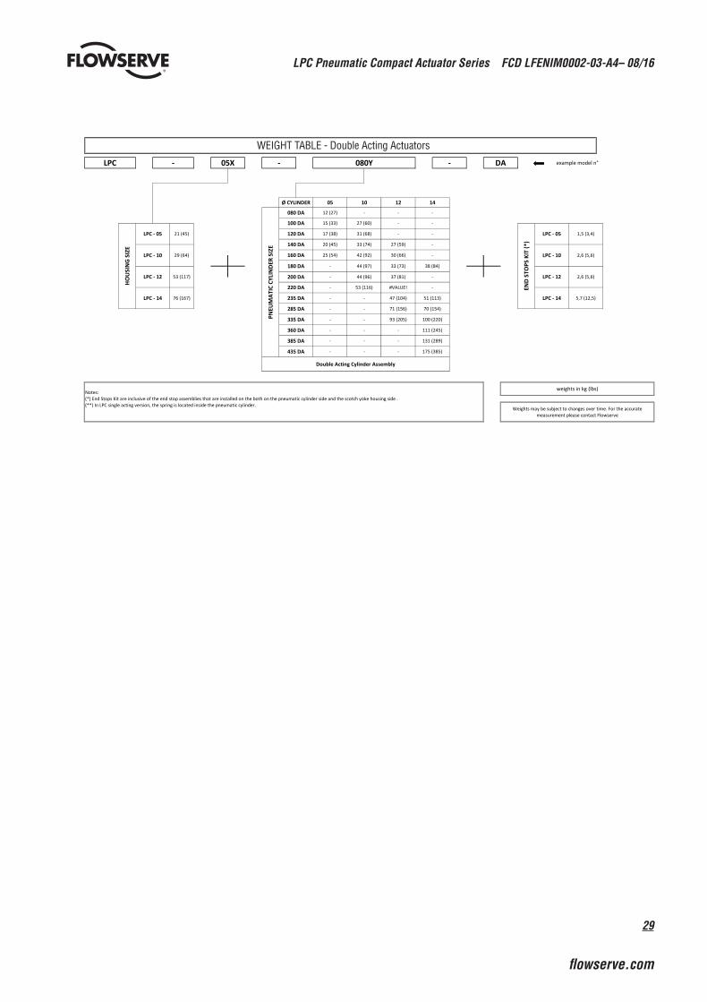
Figure 23: Modules Weight
29
LPC Pneumatic Compact Actuator Series FCD LFENIM0002-03-A4– 08/16
flowserve.com
335 DA - - 93 (205) 100 (220)
360 DA
Double Acting Cylinder Assembly
Notes:(*) End Stops Kit are inclusive of the end stop assemblies that are installed on the both on the pneumatic cylinder side and the scotch yoke housing side .(**) In LPC single acting version, the spring is located inside the pneumatic cylinder.
weights in kg (lbs)
Weights may be subject to changes over time. For the accurate measurement please contact Flowserve
385 DA - - - 131 (289)
435 DA
- -
- - - 111 (245)
LPC - 14 5,7 (12,5)
- - - 175 (385)
LPC - 12 2,6 (5,6)200 DA - 44 (96) 37 (81) -
220 DA - 53 (116) #VALUE! -
LPC - 05
-
LPC - 10 29 (64) LPC - 10
1,5 (3,4)120 DA 17 (38) 31 (68) - -
140 DA 20 (45) 33 (74) 27 (59)
2,6 (5,6)160 DA 25 (54) 42 (92) 30 (66) -
180 DA - 44 (97)
100 DA 15 (33) 27 (60) - -
HO
USI
NG
SIZ
E
LPC - 05 21 (45)
END
STO
PS K
IT (*
)
33 (73) 38 (84)
LPC - 12 53 (117)
LPC - 14 76 (167)
71 (156) 70 (154)
PNEU
MAT
IC C
YLIN
DER
SIZ
E
235 DA - - 47 (104) 51 (113)
285 DA
Ø CYLINDER 05 10 12 14
080 DA 12 (27) - - -
LPC - 05X - 080Y - DA example model n°
WEIGHT TABLE - Double Acting Actuators
LPC Pneumatic Compact Actuator Series FCD LFENIM0002-03-A4– 08/16
30
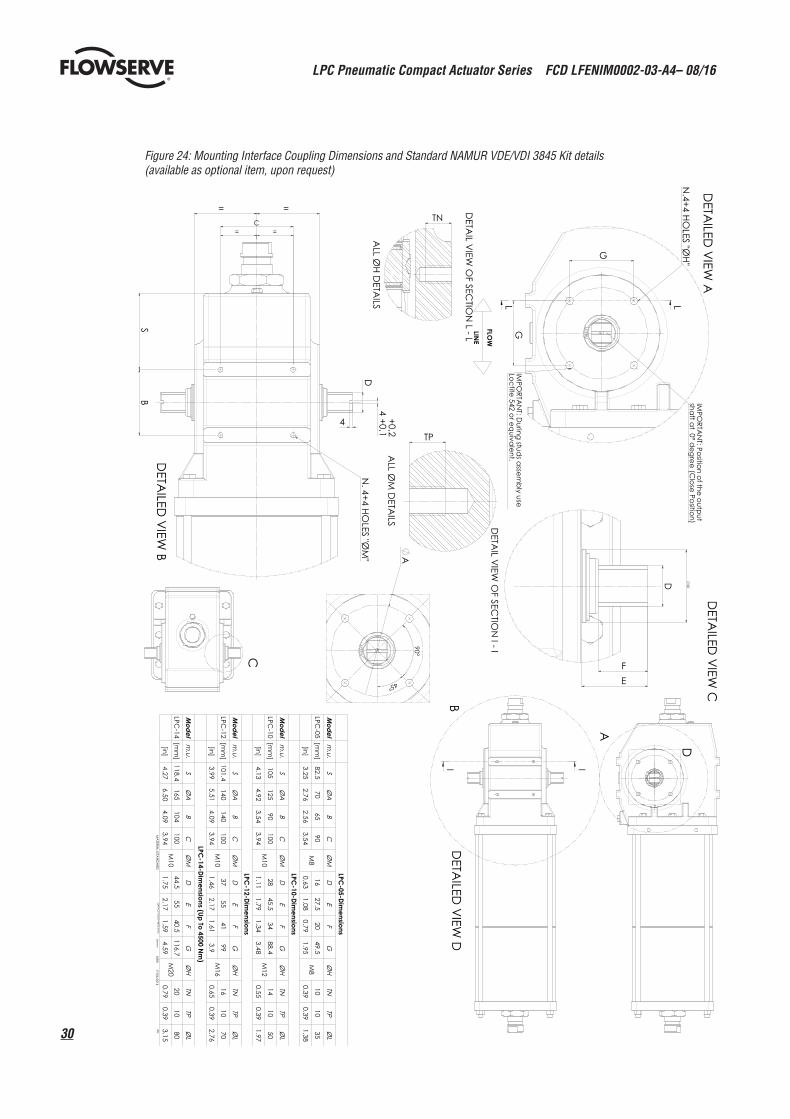
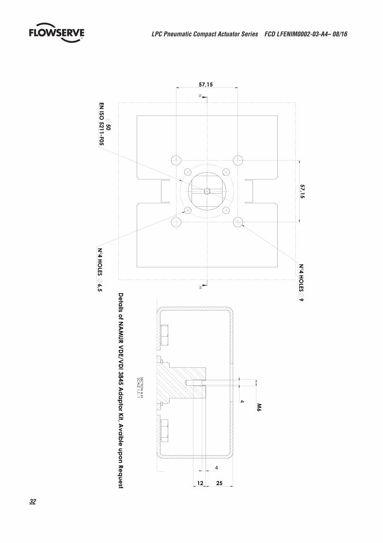
Figure 24: Mounting Interface Coupling Dimensions and Standard NAMUR VDE/VDI 3845 Kit details (available as optional item, upon request)
A
D
GG
LL
C
B
II
C
B
4D
S
4
E
D
F
A
SB
CD
EF
G
70M
816
20M
810
10
SB
CD
EF
G
LPC-10
100M
1028
34M
1214
10
SB
CD
EF
GLPC
-12140
140100
M10
3741
M16
1610
70
SB
CD
EF
GLPC
-14104
100M
10M
2020
1080
17/06/2014M
RIB

31
LPC Pneumatic Compact Actuator Series FCD LFENIM0002-03-A4– 08/16
flowserve.com
G
G NP
AA
AA
C
SB
L
EF
D M
6
4
4
12
AA
-AA
SC
ALE
SB
CE
FG
NP
LPC-14
104100
M10
77M
2020
1080
6618
LPC Pneumatic Compact Actuator Series FCD LFENIM0002-03-A4– 08/16
32
NN
4
4
N-N
33
LPC Pneumatic Compact Actuator Series FCD LFENIM0002-03-A4– 08/16
flowserve.com
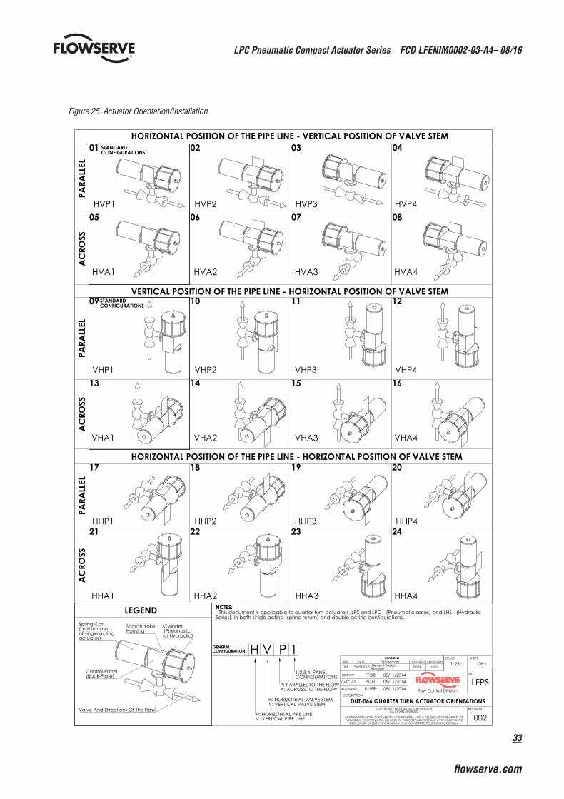
Figure 25: Actuator Orientation/Installation
Spring Can(only in case of single acting actuator)
Control Panel(Back-Plate)
Cylinder(Pneumatic or Hydraulic)
Scotch YokeHousing
Valve And Directions Of The Flow
HORIZONTAL POSITION OF THE PIPE LINE - VERTICAL POSITION OF VALVE STEM
HVA1 HVA2 HVA3 HVA4
HVP1 HVP2 HVP3 HVP4
VHP1 VHP2 VHP3 VHP4
VHA1 VHA2 VHA3 VHA4
HHP1
HHA3
HHP4
HHA2 HHA4
HHP3HHP2
HHA1LEGEND NOTES:
- This document is applicable to quarter turn actuators, LPS and LPC - (Pneumatic series) and LHS - (Hydraulic Series), in both single acting (spring return) and double acting configurations.
H V P 1GENERALCONFIGURATION:
H: HORIZONTAL PIPE LINEV: VERTICAL PIPE LINE
H: HORIZONTAL VALVE STEMV: VERTICAL VALVE STEM
P: PARALLEL TO THE FLOWA: ACROSS TO THE FLOW
1,2,3,4: PANEL CONFIGURAITONS
STANDARD CONFIGURATIONS
VERTICAL POSITION OF THE PIPE LINE - HORIZONTAL POSITION OF VALVE STEM
HORIZONTAL POSITION OF THE PIPE LINE - HORIZONTAL POSITION OF VALVE STEM
STANDARD CONFIGURATIONS
REVISIONSREV. DATE DESCRIPTION DESIGNED APPROVED
001 15/05/2015 General Design Revision FFOR PLLD
PARA
LLEL
01 02 03 04
AC
ROSS
05 06 07 08
PARA
LLEL
09 10 11 12
AC
ROSS
13 14 15 16
PARA
LLEL
17 18 19 20
AC
ROSS
21 22 23 24
LFPSSITE
Flow Control DivisionTM
1:25
DESCRIPTION
1 OF 1SHEET
REVISION:
002
DRAWN
CHECKED
APPROVED
COPYRIGHT - FLOWSERVE CORPORATION ALL RIGHTS RESERVED
INFORMATION IN THIS DOCUMENT IS CONFIDENTIAL AND IS THE EXCLUSIVE PROPERTY OF FLOWSERVE CORPORATION, DELIVERY OF THIS DOCUMENT OR ANY COPY THEREOF OR
DISCLOSURE OF SUCH INFORMATION TO UNAUTHORIZED PERSONS IS FORBIDDEN.
DUT-066 QUARTER TURN ACTUATOR ORIENTATIONS
05/11/201405/11/201405/11/2014
PLLFRPLLDFFOR
SCALE:

LPC Pneumatic Compact Actuator Series FCD LFENIM0002-03-A4– 08/16
34
Num Description Qty Spare Parts* Num Description Qty Spare Parts*
1 Grub Screw 2 21 O-Ring 2 X •
2 Plug 2 221 O-Ring 3 (2) X •
3 Scotch Yoke 1 23 End Flange 1
4 Bushing 2 24 O-Ring 1 X •
5 Retaining Ring 2 25 O-Ring 1 X •
64 Screw 2 26 Adaptor Flange 1
63 Retaining Ring 2 27 Yoke Pin 1
7 Washer 2 28 Output Shaft 1
8 Roller Bearing 2 29 Screw 6
9 O-Ring 1 X • 30 Housing 1
10 Guide Bar 1 312 O-Ring 2 X •
11 Piston Rod 1 32 Spacer 1
12 Pin 2 33 Du Bushing 2
13 Guide Block 1 34 Bushing 1
14 Bushing 2 35 Spring 1
15 Piston 1 36 Guide Ring 2 X •
165 Tie Rod 4 (8) 37 Bar Pin 6
17 Spring Can 2 38 Spanner Nut 1
185 Hex Nut 4 (8) 39 Bushing 2
19 Stop Bolt 2 403 O-Ring 2 X •
20 Hex Nut 2
Figure 26: Exploded View
* Standard maintenance spare parts for on/off applicationsX Spare parts that can be replaced.• Spare parts that can be replaced without removing the actuator from the valve.
(1: Quantity of Item 22 is 2 for Double Acting actuators and 3 for Single Acting actuators)(2: Only the O-rings on the top of the actuator can be replaced without removing the actuator from the valve)(3: Only for LPC12 and LPC14 models)(4: Only for LPC-05 and LPC-10 models)(5: Quantity variable depending on cylinder size)

35
LPC Pneumatic Compact Actuator Series FCD LFENIM0002-03-A4– 08/16
flowserve.com

flowserve.com
Flowserve LimitorqueFluid Power SystemsProduct SalesVia Rio Vallone 1720883 Mezzago (MB), ItalyPhone: +39 039 62060 1Fax: +39 039 62060 213Email: [email protected] Flowserve LimitorqueFluid Power SystemsManufacturing and OperationsVia Rio Vallone 1720883 Mezzago (MB), ItalyPhone: +39 039 62060 1Fax: +39 039 62060 213Email: [email protected] Flowserve LimitorqueFluid Power SystemsResearch and DevelopmentVia Belizzi 40/4229122 Piacenza (PC), ItalyEmail: [email protected]
To find your local Flowserve representative, visit www.flowserve.com or call: USA +1 800 225 6989 International +1 972 910 0774
LFENIM0002-03-A4 08/16 © 2016 Flowserve Corporation.
Flowserve Corporation has established industry leadership in the design and manufacture of its products. When properly selected, this Flowserve product is designed to perform its intended function safely during its useful life. However, the purchaser or user of Flowserve products should be aware that Flowserve products might be used in numerous applications under a wide variety of industrial service conditions. Although Flowserve can (and often does) provide general guidelines, it cannot provide specific data and warnings for all possible applications. The purchaser/user must therefore assume the ultimate responsibility for the proper sizing and selection, installation, operation, and maintenance of Flowserve products. The purchaser/user should read and understand the Installation Operation Maintenance (IOM) instructions included with the product, and train its employees and contractors in the safe use of Flowserve products in connection with the specific application.
While the information and specifications contained in this literature are believed to be accurate, they are supplied for informative purposes only and should not be considered certified or as a guarantee of satisfactory results by reliance thereon. Nothing contained herein is to be construed as a warranty or guarantee, express or implied, regarding any matter with respect to this product. Because Flowserve is continually improving and upgrading its product design, the specifications, dimensions and information contained herein are subject to change without notice. Should any question arise concerning these provisions, the purchaser/user should contact Flowserve Corporation at any one of its worldwide operations or offices.
© 2016 Flowserve Corporation, Irving, Texas, USA. Flowserve is a registered trademark of Flowserve Corporation.