leveraging modes and uml2 for service brokering speci cationsceur-ws.org/vol-389/paper06.pdf ·...
TRANSCRIPT
Leveraging Modes and UML2for Service Brokering Specifications
Howard Foster, Sebastian Uchitel, Jeff Kramer, and Jeff Magee
Department of Computing, Imperial College London,180 Queen’s Gate, London SW7 2BZ, UK{hf1,su2,jk,[email protected]}
Abstract. A Service-Oriented Computing (SoC) architecture consistsof a number of collaborating services to achieve one or more goals. Tra-ditionally, the focus of developing services (as components) has beenon the static binding of these services within a single context and con-strained in an individual manner. As service architectures are designedto more dynamic, where service binding and context changes with envi-ronmental disturbance, the task of designing and analysing such archi-tectures becomes more complex. UML2 introduces an extended notationto define component binding interfaces, enhanced activity diagrams andsequence diagrams. We propose the use of Modes to abstract a selectedset of services, their coordination and reconfiguration, and use modelsconstructed in UML2 to describe brokering requirements which can besynthesised for input to service brokers. The approach is implementedthrough the use of a Modes Browser, which allows service engineers toview specifications to a prototype dynamic service brokering agent.
1 Introduction
The area of service-oriented computing is exploiting the increase in use of dis-tributed component architectural patterns, descriptions and service offerings.Describing such dynamic component configurations is complex, and tradition-ally system design has presented a static view of designing such systems with theexpectation that the architecture does not evolve dynamically or can change dueto environmental disturbances. As services are the means by which componentsinteract, describing such changes is a highly important step in defining a ser-vice engineering perspective to systems development and requires an enhancedmodelling notation to support such requirements. One such notation, Darwin,is a declarative binding language which can be used to define hierarchic com-positions of interconnected components. The central abstractions managed byDarwin are components and service. In addition to its use in specifying the ar-chitecture of a distributed system, Darwin has an operational semantics for theelaboration of specifications such that they may be used at runtime to direct theconstruction of the desired system. More recently, UML2 has also introduceda number of closely related concepts to assist in describing the collaborativeand distributed nature of components, and in particular has added notations
for component architecture constraints, enhanced activity diagrams to modelworkflow and enhanced sequence diagrams to address message invocation stylesand alternative behaviours. UML has become a widespread, common practicedlanguage to support software development and as such, is highly accessible bysystem engineers.
In this paper we present an abstraction of dynamic systems using the conceptsof software modes, and we use UML2 elements to represent both the identifi-cation of Modes from a services domain (leading to a UML2 Modes Profile),the identification of self-management artifacts for operating these modes in aservice-oriented architecture, and extracting specifications for dynamic servicebrokering requirements and capabilities. In section 2, we provide a backgroundto SoC and discuss self-management techniques for distributed component ar-chitectures. In section 3 we illustrate a model-driven approach to engineeringmodes for SoC. In section 4 we provide an overview of the concept of Modes andalso detail how modes are described in elements of the UML2 notation. Section 5combines the concepts in a UML2 Extension Profile for modes, whilst in section 6we detail how a Modes Model can be used to extract deployment artifacts forService Brokers in SoC. Finally, in sections 7 and 8 we discuss limitations andprovide an indication of future work direction.
2 Background
A mode, in the context of Service-Oriented Computing (SoC) abstracts a set ofservices that collaborate towards a common goal [5]. A mode can be used to iden-tify which services are required in a service composition, and assist in specifyingorchestration and choreography requirements through service component statechanges. As a practical example, modes can assist by describing the requirementsand capabilities for dynamic service brokers in an Service-Oriented Architecture(SOA) by describing both required and provided service characteristics in a par-ticular system state. Modes also define an operating environment by way ofarchitectural constraints and of component behaviour. They can specifically beused towards addressing reconfiguration issues within a self-managed system.Self-management typically is described as a combination of self-assembly, self-healing and self-optimisation. Self-management of systems is not a new idea,with ideas from both the cybernetics [16] and system theory [15] worlds. Asdiscussed in [14] however, one of the main problems in self-management is tounderstand the relationship between the system and its subsystems: can we pre-dict a system’s behavior and can we design a system with a desired behavior?The need for such systems management is however more desired than ever beforeas we rely on distributed networks of interrelated systems through the exten-sive growth and increase in reliability of the internet. In SoC for example, adynamic service brokering solution needs to address issues like how to specifythe QoS requirements and capability, and how to select the most appropriateservice provider among several functionally-equivalent providers based on theQoS offered. An example service broker engine is called Dino [11]. Dino provides
a runtime infrastructure consisting of a number of brokers. These brokers areresponsible for, among other things, service discovery and selection on behalf ofservice requesters. Dino service requirements include both functional and QoSrequirements. Similarly, every service provider needs to define its service capabil-ity (including both functional and QoS offerings) in the specification languageprovided by Dino. A service requester forwards its requirements specificationdocument to a Dino broker at runtime, and thereby delegates the task of servicediscovery and selection to the broker. A shared understanding of the semanticsof functional and QoS properties specified by service requesters and providers isachieved by referring to common ontologies.
Another key part in the self-management of a dynamic SOA is the runtimepolicy which specifies how and when reconfigurations occur. In [17], a policy setfor SOA is described as being part of one of four categories for either process(the behaviour required), architecture (the configuration and reconfiguration ofservice components), operational (non-functional properties such as QoS levels)and relationship (trust and functional support). A policy for a system designedfor an SOA architecture should consider each of these. Although policies clearlycover much more than QoS, in this paper we focus on the architecture con-straints, and specifying QoS constraints on service operation and contracts fordynamic service brokering.
2.1 Related Work
Related work falls in to several categories. Firstly self-management of SOA’s hasattracted both policy and technology management work. In [8] for example, theauthors describe a state-space modelling approach for system policies to facilitateself-management of enterprise services. Although concentrating on an enterprisemodel there is no running example of how this translates to a physical runtimeusage. Whilst in [1] they focus on low-level administration of service networks tomonitor service quality and react to notification events. Secondly, for modellingrequirements of services and SOA there is also IBM’s UML2 Profile for SoftwareServices [6]. This profile provides a set of stereotypes that represent featuresfor the service engineering life cycle, including a service specification (interface),gateway (ports) and collaboration (behaviour specifications). In [2] the authorspresent a profile aimed at specifying both architectural and behaviour aspects ofSOA in UML for both web and non-web deployment environments. A particulardifference in this work is that there is a focus on service messages and routing,whilst also being able to specify registry and adapter elements. The SENSORIAproject has also extended UML for SoC specifications in [7], adding stereotypesfor functional and non-functional requirements, contracts and behavioural mod-elling of services. Transformations of UML for SOA deployment artifacts hasbeen discussed in [9]. Here the authors present an approach to transform UMLuse case diagrams to object diagrams for implementation (in further transfor-mation approaches). Generally what is missing from these existing profile ap-proaches is the ability to identify the requirements and capabilities of servicesand then to elaborate on the dynamic changes anticipated for self-management.
Our work expands on the ideas presented in these profiles by considering themore dynamic change of architectures, for self-management and brokering in adynamic SOA.
3 Approach
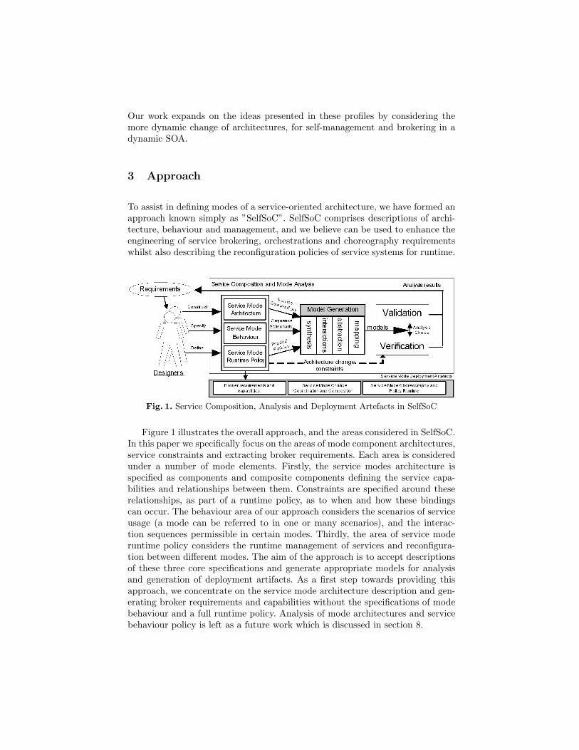
To assist in defining modes of a service-oriented architecture, we have formed anapproach known simply as ”SelfSoC”. SelfSoC comprises descriptions of archi-tecture, behaviour and management, and we believe can be used to enhance theengineering of service brokering, orchestrations and choreography requirementswhilst also describing the reconfiguration policies of service systems for runtime.
Fig. 1. Service Composition, Analysis and Deployment Artefacts in SelfSoC
Figure 1 illustrates the overall approach, and the areas considered in SelfSoC.In this paper we specifically focus on the areas of mode component architectures,service constraints and extracting broker requirements. Each area is consideredunder a number of mode elements. Firstly, the service modes architecture isspecified as components and composite components defining the service capa-bilities and relationships between them. Constraints are specified around theserelationships, as part of a runtime policy, as to when and how these bindingscan occur. The behaviour area of our approach considers the scenarios of serviceusage (a mode can be referred to in one or many scenarios), and the interac-tion sequences permissible in certain modes. Thirdly, the area of service moderuntime policy considers the runtime management of services and reconfigura-tion between different modes. The aim of the approach is to accept descriptionsof these three core specifications and generate appropriate models for analysisand generation of deployment artifacts. As a first step towards providing thisapproach, we concentrate on the service mode architecture description and gen-erating broker requirements and capabilities without the specifications of modebehaviour and a full runtime policy. Analysis of mode architectures and servicebehaviour policy is left as a future work which is discussed in section 8.
3.1 Case Study
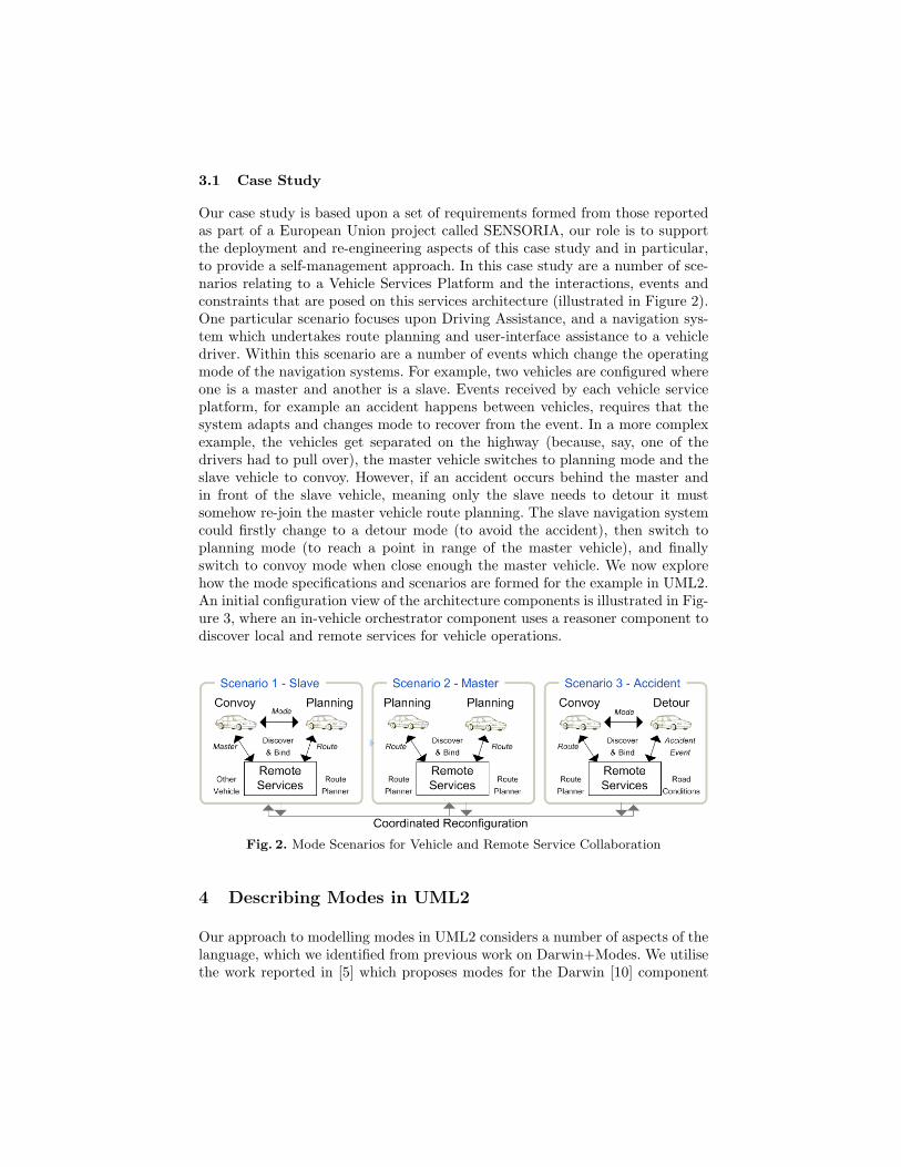
Our case study is based upon a set of requirements formed from those reportedas part of a European Union project called SENSORIA, our role is to supportthe deployment and re-engineering aspects of this case study and in particular,to provide a self-management approach. In this case study are a number of sce-narios relating to a Vehicle Services Platform and the interactions, events andconstraints that are posed on this services architecture (illustrated in Figure 2).One particular scenario focuses upon Driving Assistance, and a navigation sys-tem which undertakes route planning and user-interface assistance to a vehicledriver. Within this scenario are a number of events which change the operatingmode of the navigation systems. For example, two vehicles are configured whereone is a master and another is a slave. Events received by each vehicle serviceplatform, for example an accident happens between vehicles, requires that thesystem adapts and changes mode to recover from the event. In a more complexexample, the vehicles get separated on the highway (because, say, one of thedrivers had to pull over), the master vehicle switches to planning mode and theslave vehicle to convoy. However, if an accident occurs behind the master andin front of the slave vehicle, meaning only the slave needs to detour it mustsomehow re-join the master vehicle route planning. The slave navigation systemcould firstly change to a detour mode (to avoid the accident), then switch toplanning mode (to reach a point in range of the master vehicle), and finallyswitch to convoy mode when close enough the master vehicle. We now explorehow the mode specifications and scenarios are formed for the example in UML2.An initial configuration view of the architecture components is illustrated in Fig-ure 3, where an in-vehicle orchestrator component uses a reasoner component todiscover local and remote services for vehicle operations.
Fig. 2. Mode Scenarios for Vehicle and Remote Service Collaboration
4 Describing Modes in UML2
Our approach to modelling modes in UML2 considers a number of aspects of thelanguage, which we identified from previous work on Darwin+Modes. We utilisethe work reported in [5] which proposes modes for the Darwin [10] component
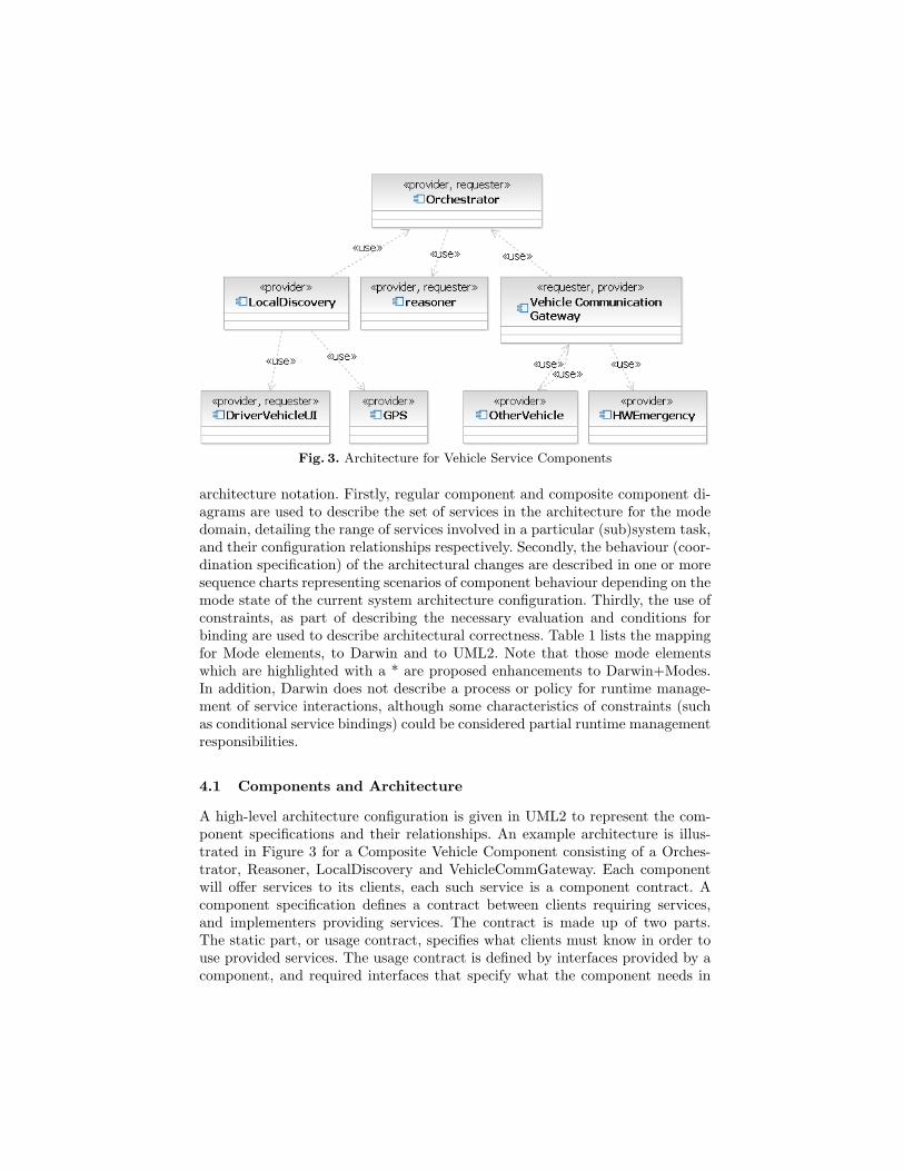
Fig. 3. Architecture for Vehicle Service Components
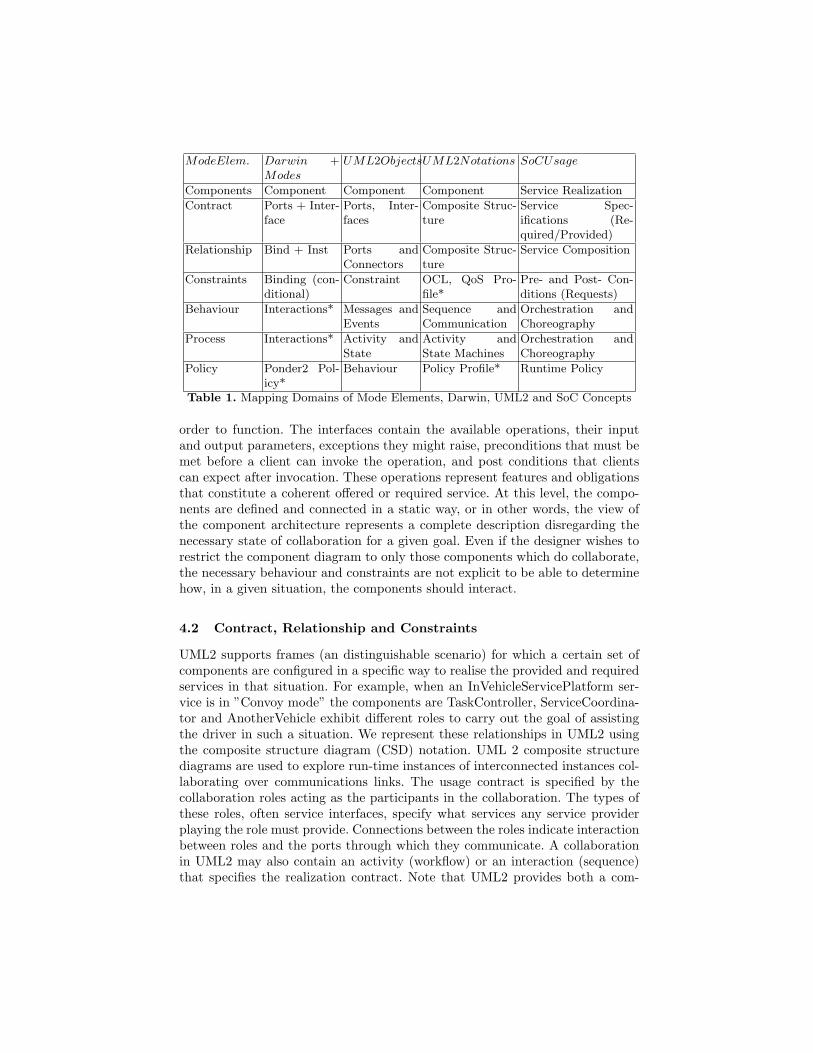
architecture notation. Firstly, regular component and composite component di-agrams are used to describe the set of services in the architecture for the modedomain, detailing the range of services involved in a particular (sub)system task,and their configuration relationships respectively. Secondly, the behaviour (coor-dination specification) of the architectural changes are described in one or moresequence charts representing scenarios of component behaviour depending on themode state of the current system architecture configuration. Thirdly, the use ofconstraints, as part of describing the necessary evaluation and conditions forbinding are used to describe architectural correctness. Table 1 lists the mappingfor Mode elements, to Darwin and to UML2. Note that those mode elementswhich are highlighted with a * are proposed enhancements to Darwin+Modes.In addition, Darwin does not describe a process or policy for runtime manage-ment of service interactions, although some characteristics of constraints (suchas conditional service bindings) could be considered partial runtime managementresponsibilities.
4.1 Components and Architecture
A high-level architecture configuration is given in UML2 to represent the com-ponent specifications and their relationships. An example architecture is illus-trated in Figure 3 for a Composite Vehicle Component consisting of a Orches-trator, Reasoner, LocalDiscovery and VehicleCommGateway. Each componentwill offer services to its clients, each such service is a component contract. Acomponent specification defines a contract between clients requiring services,and implementers providing services. The contract is made up of two parts.The static part, or usage contract, specifies what clients must know in order touse provided services. The usage contract is defined by interfaces provided by acomponent, and required interfaces that specify what the component needs in
ModeElem. Darwin +Modes
UML2ObjectsUML2Notations SoCUsage
Components Component Component Component Service Realization
Contract Ports + Inter-face
Ports, Inter-faces
Composite Struc-ture
Service Spec-ifications (Re-quired/Provided)
Relationship Bind + Inst Ports andConnectors
Composite Struc-ture
Service Composition
Constraints Binding (con-ditional)
Constraint OCL, QoS Pro-file*
Pre- and Post- Con-ditions (Requests)
Behaviour Interactions* Messages andEvents
Sequence andCommunication
Orchestration andChoreography
Process Interactions* Activity andState
Activity andState Machines
Orchestration andChoreography
Policy Ponder2 Pol-icy*
Behaviour Policy Profile* Runtime Policy
Table 1. Mapping Domains of Mode Elements, Darwin, UML2 and SoC Concepts
order to function. The interfaces contain the available operations, their inputand output parameters, exceptions they might raise, preconditions that must bemet before a client can invoke the operation, and post conditions that clientscan expect after invocation. These operations represent features and obligationsthat constitute a coherent offered or required service. At this level, the compo-nents are defined and connected in a static way, or in other words, the view ofthe component architecture represents a complete description disregarding thenecessary state of collaboration for a given goal. Even if the designer wishes torestrict the component diagram to only those components which do collaborate,the necessary behaviour and constraints are not explicit to be able to determinehow, in a given situation, the components should interact.
4.2 Contract, Relationship and Constraints
UML2 supports frames (an distinguishable scenario) for which a certain set ofcomponents are configured in a specific way to realise the provided and requiredservices in that situation. For example, when an InVehicleServicePlatform ser-vice is in ”Convoy mode” the components are TaskController, ServiceCoordina-tor and AnotherVehicle exhibit different roles to carry out the goal of assistingthe driver in such a situation. We represent these relationships in UML2 usingthe composite structure diagram (CSD) notation. UML 2 composite structurediagrams are used to explore run-time instances of interconnected instances col-laborating over communications links. The usage contract is specified by thecollaboration roles acting as the participants in the collaboration. The types ofthese roles, often service interfaces, specify what services any service providerplaying the role must provide. Connections between the roles indicate interactionbetween roles and the ports through which they communicate. A collaborationin UML2 may also contain an activity (workflow) or an interaction (sequence)that specifies the realization contract. Note that UML2 provides both a com-
munication diagram and collaboration diagrams. The communication diagramis an extended version of a collaborative diagram from version 1.x and the newcollaboration diagram is a composite structure diagram. The later form providesa way to describe components and their roles for a given mode (a form muchcloser to the meaning of a collaboration scenario).
A constraint in UML2 contains a ValueSpecification that specifies additionalsemantics for one or more elements. A constraint is a condition (a Boolean ex-pression) that restricts the extension of the associated element beyond what isimposed by the other language constructs applied to that element. Constraintcontains an optional name, although they are commonly unnamed. Certain kindsof constraints (such as an association constraint) are predefined in UML, oth-ers may be user-defined. One predefined language for writing architectural con-straints is the Object Constraint Language (OCL) [12]. OCL is a formal languageused to describe expressions on UML models. They are used to express invariantconditions that must be held for the system being modeled. These are describedas pre- and post-conditions of the evaluation.
5 A Modes Profile
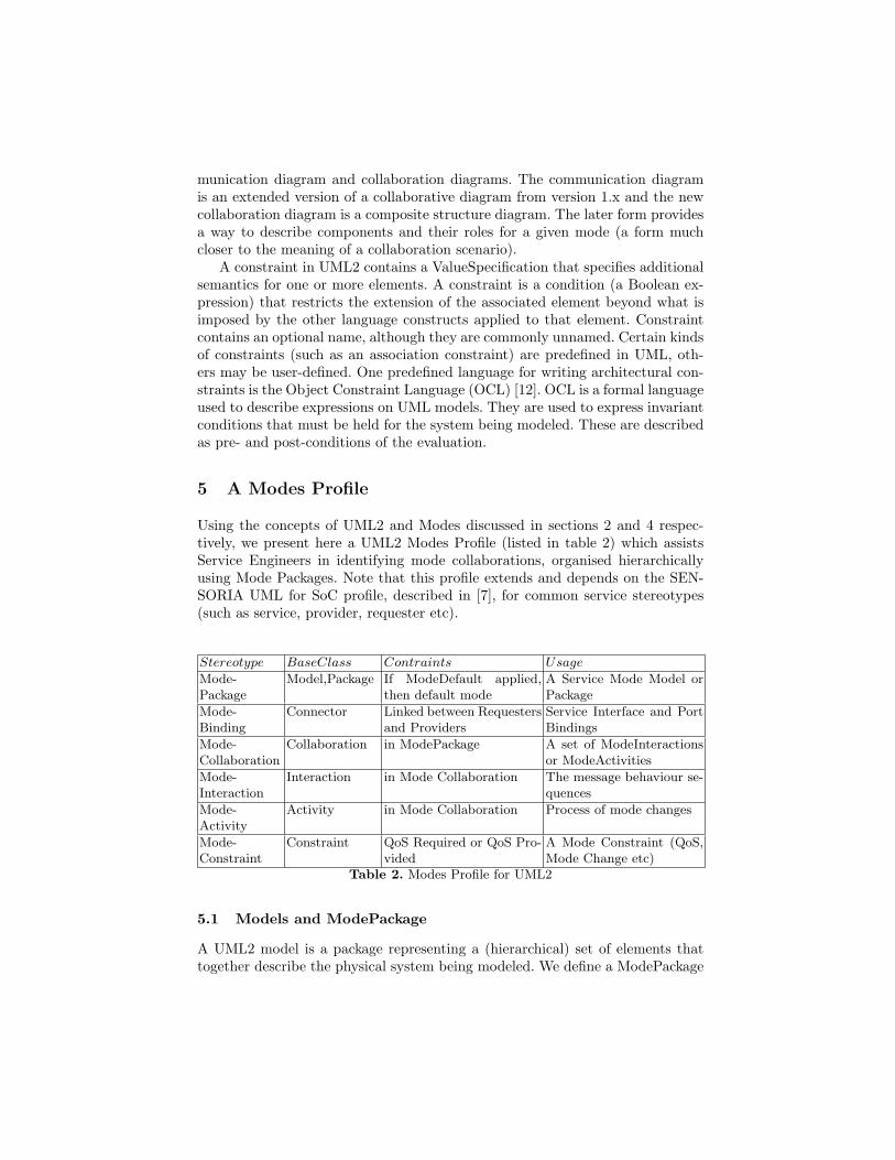
Using the concepts of UML2 and Modes discussed in sections 2 and 4 respec-tively, we present here a UML2 Modes Profile (listed in table 2) which assistsService Engineers in identifying mode collaborations, organised hierarchicallyusing Mode Packages. Note that this profile extends and depends on the SEN-SORIA UML for SoC profile, described in [7], for common service stereotypes(such as service, provider, requester etc).
Stereotype BaseClass Contraints Usage
Mode-Package
Model,Package If ModeDefault applied,then default mode
A Service Mode Model orPackage
Mode-Binding
Connector Linked between Requestersand Providers
Service Interface and PortBindings
Mode-Collaboration
Collaboration in ModePackage A set of ModeInteractionsor ModeActivities
Mode-Interaction
Interaction in Mode Collaboration The message behaviour se-quences
Mode-Activity
Activity in Mode Collaboration Process of mode changes
Mode-Constraint
Constraint QoS Required or QoS Pro-vided
A Mode Constraint (QoS,Mode Change etc)
Table 2. Modes Profile for UML2
5.1 Models and ModePackage
A UML2 model is a package representing a (hierarchical) set of elements thattogether describe the physical system being modeled. We define a ModePackage
stereotype as an extension of this definition with a stereotype to designate thata package is being described for a system mode configuration. A ModePackageis expected to have one ModePolicy and one or more elements of type Mod-eCollaboration, ModeActivity, Events and Signals. A UML2 Model (for Modes)may contain more than one nested package with the stereotype of ModePackage,to provide a set of modes that the system may accommodate. As standard, aUML2 package can import other packages, individual elements from these pack-ages or all their member elements. Packages may also be merged, which alsoserves a feature of combining modes together. In the case study described in sec-tion 3.1 , we would stereotype each vehicle mode as a ”ModePackage”. At thislevel of the model, a ModeActivity element in this package serves to describethe ModeCollaboration transitions within the parent mode package.
5.2 ModeCollaboration and ModeBinding
A ModeCollaboration is a UML2 Collaboration containing a Composite Struc-ture Diagram (CSD) to represent the collaborating service components relation-ships in this mode, one or more ModeInteraction diagrams (sequence and com-munication diagrams describing the expected message behaviour between theservice components) for this mode, and one or more ModeActivity diagrams torepresent the higher level ordering of the service interaction behaviour describedin the ModeInteraction diagrams. At this level of the package, the ModeActivityserves as a higher-level Message Sequence Chart (hMSC) and the InteractionDiagrams as Basic Message Sequence Charts (bMSCs). Within each CSD, theUML2 element of Connector is stereotyped as a ModeBinding. A Connectorrepresents a (mode) relationship between service components in the collabora-tion architecture. Also within each CSD, a connector represents a physical linkbetween service component ports, which also contain one or more service in-terfaces (both required and provided types). Thus, a ModeBinding represents arequired connection (or instantiation) in order to carry out the mode behaviouras described in a collaboration interaction set.
5.3 ModeInteraction and ModeActivity
A ModeInteraction contains a single interaction (sequence) diagram and op-tionally a single communication diagram. The sequence diagram is a messagesequence chart describing the sequence of interactions between service compo-nents in the mode collaboration. A communication diagram provides an alterna-tive view of the sequence logic for the mode interactions, in a sense a ”bird’s eye”view of the way the service components collaborate for a given configuration. AModeActivity is a UML2 Activity which describes a computational process, orin the domain of SoC, a service composition process. The ModeActivity can bespecified at either the model level (as a representation of a process to transitionbetween mode collaborations) or at the ModeCollaboration level, to describe thesequencing of ModeInteractions in a mode collaboration.
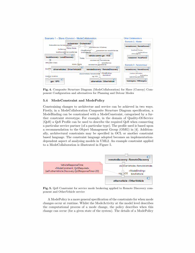
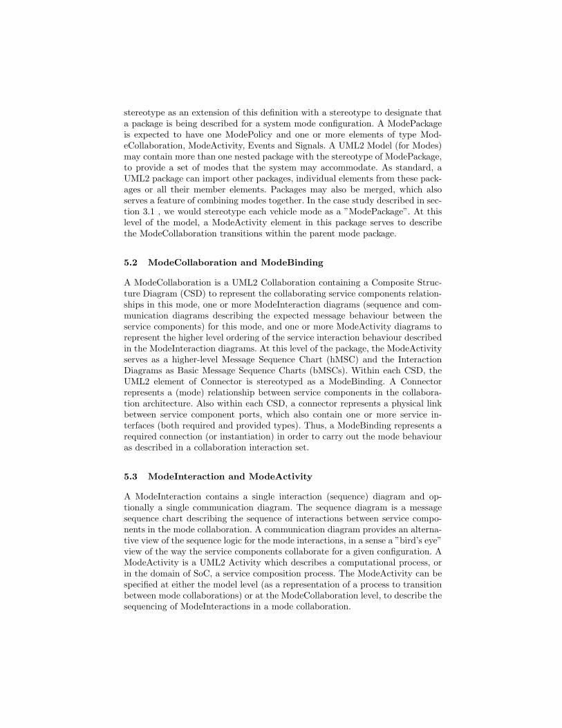
Fig. 4. Composite Structure Diagram (ModeCollaboration) for Slave (Convoy) Com-ponent Configuration and alternatives for Planning and Detour Modes
5.4 ModeConstraint and ModePolicy
Constraining changes to architectue and service can be achieved in two ways.Firstly, in a ModeCollaboration Composite Structure Diagram specification, aModeBinding can be constrained with a ModeConstraint, categorised by a fur-ther constraint stereotype. For example, in the domain of Quality-Of-Service(QoS) a QoS Profile can be used to describe the required QoS when connectinga particular service partner (of a particular type). The profile used is based upona recommendation to the Object Management Group (OMG) in [4]. Addition-ally, architectural constraints may be specified in OCL or another constraintbased language. The constraint language adopted becomes an implementation-dependent aspect of analysing models in UML2. An example constraint appliedto a ModeCollaboration is illustrated in Figure 5.
Fig. 5. QoS Constraint for service mode brokering applied to Remote Discovery com-ponent and OtherVehicle service
A ModePolicy is a more general specification of the constraints for when modechanges occur at runtime. Whilst the ModeActivity at the model level describesthe computational process of a mode change, the policy describes when thischange can occur (for a given state of the system). The details of a ModePolicy
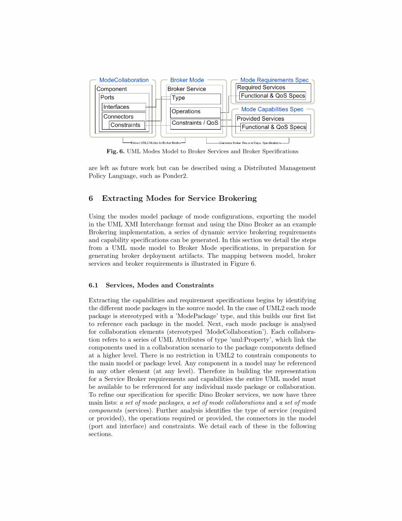
Fig. 6. UML Modes Model to Broker Services and Broker Specifications
are left as future work but can be described using a Distributed ManagementPolicy Language, such as Ponder2.
6 Extracting Modes for Service Brokering
Using the modes model package of mode configurations, exporting the modelin the UML XMI Interchange format and using the Dino Broker as an exampleBrokering implementation, a series of dynamic service brokering requirementsand capability specifications can be generated. In this section we detail the stepsfrom a UML mode model to Broker Mode specifications, in preparation forgenerating broker deployment artifacts. The mapping between model, brokerservices and broker requirements is illustrated in Figure 6.
6.1 Services, Modes and Constraints
Extracting the capabilities and requirement specifications begins by identifyingthe different mode packages in the source model. In the case of UML2 each modepackage is stereotyped with a ’ModePackage’ type, and this builds our first listto reference each package in the model. Next, each mode package is analysedfor collaboration elements (stereotyped ’ModeCollaboration’). Each collabora-tion refers to a series of UML Attributes of type ’uml:Property’, which link thecomponents used in a collaboration scenario to the package components definedat a higher level. There is no restriction in UML2 to constrain components tothe main model or package level. Any component in a model may be referencedin any other element (at any level). Therefore in building the representationfor a Service Broker requirements and capabilities the entire UML model mustbe available to be referenced for any individual mode package or collaboration.To refine our specification for specific Dino Broker services, we now have threemain lists: a set of mode packages, a set of mode collaborations and a set of modecomponents (services). Further analysis identifies the type of service (requiredor provided), the operations required or provided, the connectors in the model(port and interface) and constraints. We detail each of these in the followingsections.
6.2 Service Components and Connectors
As described in section 2, the Dino broker considers two types of service re-quirements; 1) required services for a given mode and 2) provided services toannounce capabilities that can be matched for a mode of operation. Identifyingthe type of a service in the mode model relies on alternative properties. Firstly,if the component has required interfaces or is stereotyped as a ’requestor’, thenthe service is marked as a requestor service. Alternatively if the component hasa provided interface or is stereotyped as a ’provider’ then the service is markedas a provider service. Both requester and provider stereotypes may be appliedeither by an additional UML profile extension or by adding these keywords asa direct extension to the property of the collaboration. Although we identifyrequestor and provider types, the Dino requirements and capabilities only con-sider providers. If a component in the mode collaboration has no interfaces orstereotype, then it is excluded as a service from the broker specifications list.
A connector may or may not exist between a pair of requester and providertype components. To evaluate this we firstly check whether a component has anyports. If ports are located, then for each port a list of connectors for that port isretrieved. The binding between a component refers to an Assembly Connector inUML2. An assembly connector is referenced by a usage, linking the connector,interface and port between components. Therefore, for each connector attachedto a port the ends are evaluated against any component in the mode model.Any components located which match the requester component are ignored.This leaves at least one provider component. For each provider component theservice operations are extracted as described in section 6.3.
6.3 Service Operations
Building the representation for operations of each type of service requires usto refer to the interfaces of the component in a mode collaboration. Note thatoperations are not just those which are advertised as offered by the service, butalso a list of operations required by a requester component type. Firstly thecapabilities of the Dino service are added to the service model in our transfor-mation. If the component has a provided interface, then each operation type, idand name is appended to the Dino Service representation as provided operations.For a provider of operations, building the Dino Service operations is relativelystraightforward. However for a requester type service, the connector betweenservice requester and provider instances must be referenced.
6.4 Constraints
We also support extracting ModeConstraints for service bindings, or more specif-ically a quality of service attribute applied to assembly connectors between twoor more components. A ModeConstraint is expected to be expressed in a particu-lar format. For our case study we used the OMG recommendation for a QoS andFault Tolerance profile in UML [4]. In this example a QoSRequired constraint is
applied to the assembly connector between the remote discovery and other ve-hicle services. The QoSRequired constraint consists of two key aspects. Firstly,that it has applied the QoSRequired stereotype from the OMG QoS Profile, andsecondly that it specifies a Object Constraint Language (OCL) statement whichconstraints the binding operation. The binding operation, in this case, will beundertaken by the Dino broker. As a final step in building required and providedDino services, the extract routine traverses the service connectors for any appliedconstraints. If a constraint is located, then a new QoS attribute is added to theDino service. The OCL statement is evaluated for object and value expressions,and also added to the Dino service.
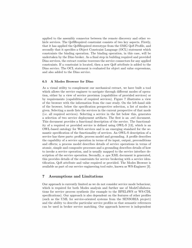
6.5 A Modes Browser for Dino
As a visual utility to complement our mechanical extract, we have built a toolwhich allows the service engineer to navigate through different modes of opera-tion, either by a view of service provision (capabilities of provided services) orby requirements (capabilities of required services). Figure 7 illustrates a viewof the browser with the information from the case study. On the left-hand sideof the browser, below the specification perspective selection, a list of modes isgiven. Selecting a mode lists the services in the current perspective of that mode(i.e. all required services). Selecting a service in the list below this, generatesa selection of two service deployment artifacts. The first is an .owl document.This document provides a functional description of the service. The functional-ity of a required or provided service is defined using OWL-S [13], which is anOWL-based ontology for Web services and is an emerging standard for the se-mantic specification of the functionality of services. An OWL-S description of aservice has three parts: profile, process model and grounding. A profile describesthe capability of a service operation in terms of its input, output, preconditionsand effects; a process model describes details of service operations in terms ofatomic, simple and composite processes and a grounding describes details of howto invoke a service operation, and is usually mapped to the service interface de-scription of the service operation. Secondly, a .qos XML document is generated,this provides details of the constraints for service brokering with a service iden-tification, QoS attribute and value required or provided. The Modes Browser isavailable as part of our service engineering tool suite, known as WS-Engineer [3].
7 Assumptions and Limitations
Our approach is currently limited as we do not consider service mode behaviour,which is required for both Modes analysis and further use of ModeCollabora-tions for service process synthesis (for example to the BPEL4WS or WS-CDLspecifications). Our approach is also dependent on the features of other profiles(such as the UML for service-oriented systems from the SENSORIA project)and the ability to describe particular service profiles so that semantic referencescan be used in broker service matching. Our approach however is independent
Fig. 7. Dino Service Broker Browser using Vehicle UML Modes Specification
of the actual semantics used for this. We concentrate on allowing the engineerto form the appropriate patterns of service architecture changes and to thengenerate some useful specifications which can later be used for deployment andexecution.
8 Conclusions and Future Work
We believe that the notion of modes helps engineers abstract appropriate ele-ments, behaviour and policy from the services domain, and can facilitate thespecification of appropriate control over both architectural change and servicebehaviour. In this paper we have presented our approach to the modellingof service-oriented computing component architectures using an abstraction ofmodes to represent the changes in such an architecture. Our future work willexplore how these artifacts are more accurately built and analysed, and also onhow our approach can assist in the dynamic invocation of services given compo-nent requirements and capabilities. We will also detail an approach to generatingan implementation layer for switching modes, perhaps through the synthesis ofservice composition specifications in standards such as BPEL4WS and WS-CDL,representing the tasks for reconfiguration and coordination of services in such anarchitecture. This work has been partially sponsored by the EU funded projectSENSORIA (IST-2005-016004).
References
1. Claudia Baltes, Patrick Koppen, and Paul Muller. Self-management in heteroge-nous networks using a service-oriented architecture. In Consumer Communicationsand Networking Conference, 2007 (CCNC 2007), pages 420–424, Las Vegas, NV,USA, 2007. IEEE Computer Society.
2. Vina Ermagan and Ingolf H. Kruger. A uml2 profile for service modeling. InMoDELS, Lecture Notes in Computer Science, pages 360–374. Springer, 2007.
3. Howard Foster, Sebastian Uchitel, Jeff Magee, and Jeff Kramer. Ws-engineer:toolsupport for model-based engineering of web service compositions and choreography.In IEEE International Conference on Software Engineering (ICSE2006), Shanghai,China, 2006. IEEE.
4. Object Management Group. Uml profile for modeling quality of service and faulttolerance characteristics and mechanisms. Request For Proposal - AD/02-01/07,2002.
5. D. Hirsch, J.Kramer, J.Magee, and S. Uchitel. Modes for software architectures.In Third European Workshop on Software Architecture. Springer, 2006.
6. Simon Johnston. Uml 2.0 profile for software services. Availableat http://www-128.ibm.com/developerworks/rational/library/05/419_soa, 2005.
7. Nora Koch, Philip Mayer, Reiko Heckel, Lszl Gnczy, and Carlo Montangero. D1.4b:Uml for service-oriented systems. Technical report, October 2007.
8. Vibhore Kumar, Brian F. Cooper, Greg Eisenhauer, and Karsten Schwan. imanage:Policy-driven self-management for enterprise-scale systems. In Renato Cerqueiraand Roy H. Campbell, editors, Middleware, volume 4834 of Lecture Notes in Com-puter Science, pages 287–307. Springer, 2007.
9. Ricardo J. Machado, Joao M. Fernandes, Paula Monteiro, and Helena Rodrigues.Transformation of uml models for service-oriented software architectures. In Pro-ceedings of the 12th IEEE International Conference and Workshops on Engineeringof Computer-Based Systems, pages 173–182, Washington, DC, USA, 2005.
10. J. Magee, N. Dulay, S. Eisenbach, and J. Kramer. Specifying Distributed SoftwareArchitectures. In W. Schafer and P. Botella, editors, Proc. 5th European SoftwareEngineering Conf. (ESEC 95), volume 989, pages 137–153, Sitges, Spain, 1995.Springer-Verlag, Berlin.
11. Arun Mukhija, Andrew Dingwall-Smith, and David S. Rosenblum. Qos-aware ser-vice composition in dino. In ECOWS ’07: Proceedings of the Fifth European Con-ference on Web Services, pages 3–12, Washington, DC, USA, 2007. IEEE ComputerSociety.
12. Object ManagementGroup (OMG). The object constraint language specification2.0. Available at http://www.omg.org/docs, 2007.
13. OWL-S. Owl-based web service ontology. Web Resource, 2007.14. Peter Van Roy. Self management and the future of software design. In Formal
Aspects of Component Software (FACS ’06), Prague, Czech Republic, 2006.15. Ludwig Von Bertalanffy. General System Theory: Foundations, Development, Ap-
plications. george braziller, New York, NY, 1969.16. Norbert Wiener. Cybernetics, or Control and Communication in the Animal and
the Machine. MIT press, Cambridge, MA, 1948.17. Lawrence Wilkes. Policy driven practices for soa. Available at http:
//www.omg.org/news/meetings/workshops/SOA_MDA_WS_Workshop_CD/02-3_Wilkes.pdf, 2006.