leveraged freedom chair east african trial data ...web.mit.edu/awinter/public/lfc daq...
TRANSCRIPT

Amos Winter Physics 123
Fall 2009 Extra Credit Project
Leveraged Freedom Chair East African Trial
Data Acquisition System
1 Introduction The aim of this project was to design a data acquisition system to record
biomechanical and mechanical performance data from the Leveraged Freedom Chair
(LFC), a wheelchair being developed at MIT for use in developing countries. The LFC is
propelled by pushing two levers, one connected to each rear wheel, in a bench press-like
motion, as shown in Fig. 1. Holding the levers far from the pivots creates high torque for
traveling on soft or steep ground, while grasping near the pivots increases angular
velocity to zip across flat surfaces. The LFC can travel 10-20% faster than a wheelchair
on flat roads and traverse deep mud and sand, terrain virtually impassible with
wheelchairs or hand-powered tricycles. For indoor use, the LFC morphs into a
conventional wheelchair by simply removing the levers and stowing them behind the
seat.
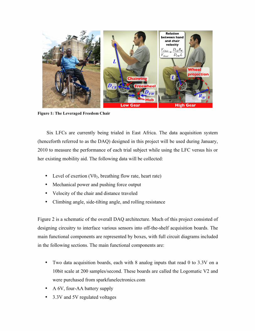
Figure 1: The Leveraged Freedom Chair
Six LFCs are currently being trialed in East Africa. The data acquisition system
(henceforth referred to as the DAQ) designed in this project will be used during January,
2010 to measure the performance of each trial subject while using the LFC versus his or
her existing mobility aid. The following data will be collected:
• Level of exertion (V02, breathing flow rate, heart rate)
• Mechanical power and pushing force output
• Velocity of the chair and distance traveled
• Climbing angle, side-tilting angle, and rolling resistance
Figure 2 is a schematic of the overall DAQ architecture. Much of this project consisted of
designing circuitry to interface various sensors into off-the-shelf acquisition boards. The
main functional components are represented by boxes, with full circuit diagrams included
in the following sections. The main functional components are:
• Two data acquisition boards, each with 8 analog inputs that read 0 to 3.3V on a
10bit scale at 200 samples/second. These boards are called the Logomatic V2 and
were purchased from sparkfunelectronics.com
• A 6V, four-AA battery supply
• 3.3V and 5V regulated voltages

• Four strain gage circuits that measure forces on the levers
• Four string potentiometers that measure angular deflection of the levers and the
user’s hand position
• A heart rate sensor, with the receiving element and transmitter provided by Polar
• A speed sensor, adapted from a bicycle computer
• A V02 sensor, purchased from Vernier.com
• A spirometer sensor (breathing flow rate), purchased from Vernier.com
• A counter that shows the test number and outputs an identifier voltage to the DAQ
• A three-axis accelerometer that measures tip and tilt of the wheelchair (not shown
as separate circuit because accelerometer attached to DAQ as shown in Fig. 1)
• Status lights to indicate that each data line is connected to the acquisition boards
and is functional
• A record switch, which puts a starting flag in the data to sync both acquisition
boards
• A low battery light to indicate when the batteries are nearly dead
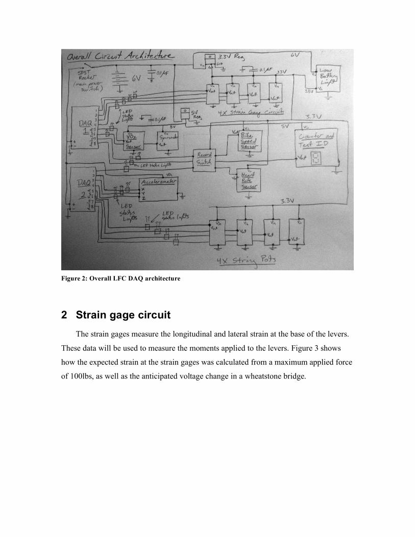
Figure 2: Overall LFC DAQ architecture
2 Strain gage circuit The strain gages measure the longitudinal and lateral strain at the base of the levers.
These data will be used to measure the moments applied to the levers. Figure 3 shows
how the expected strain at the strain gages was calculated from a maximum applied force
of 100lbs, as well as the anticipated voltage change in a wheatstone bridge.
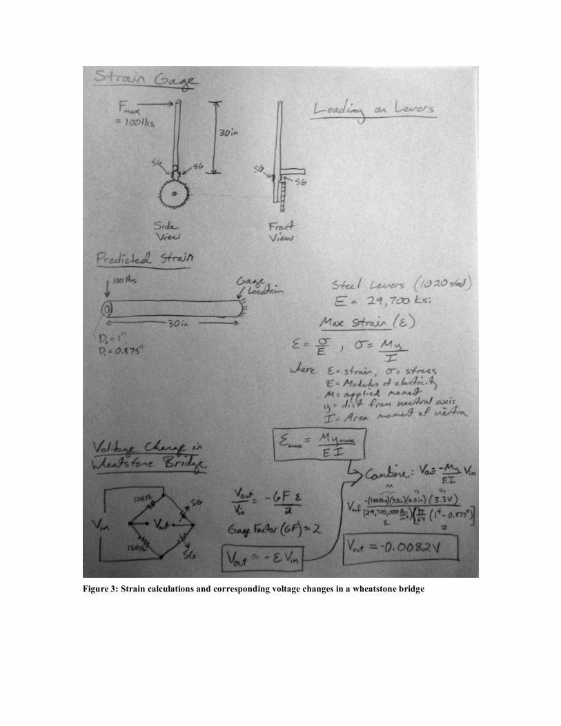
Figure 3: Strain calculations and corresponding voltage changes in a wheatstone bridge
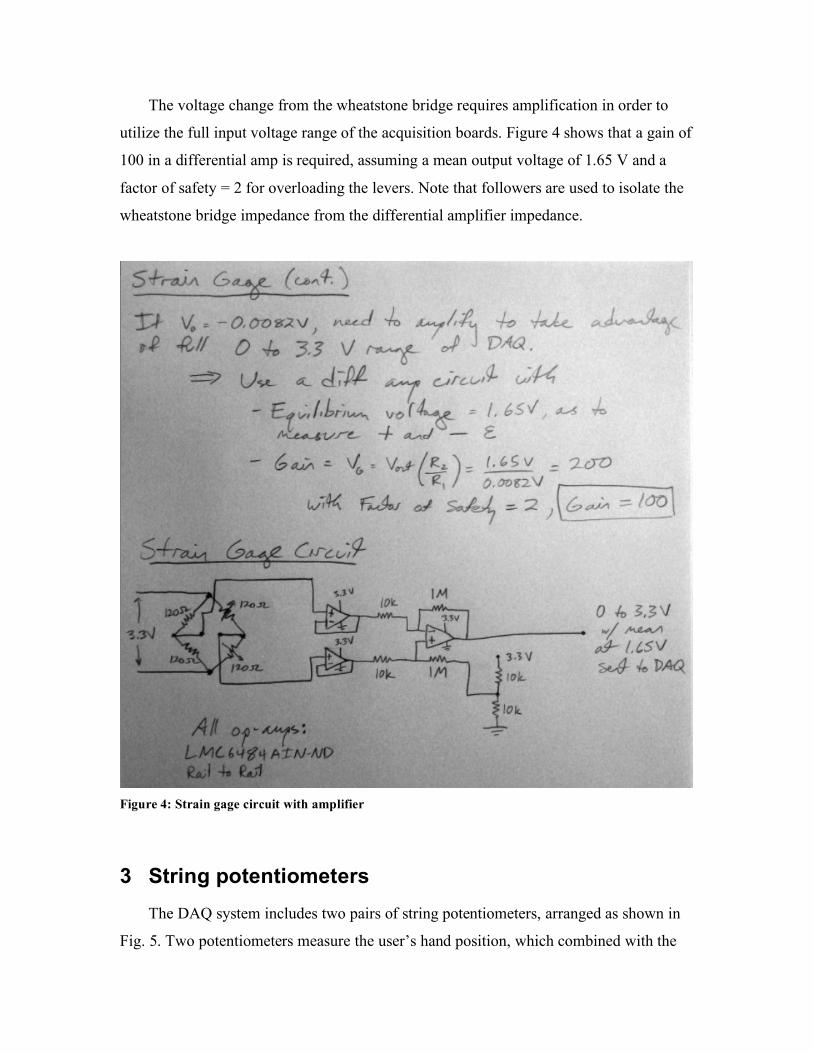
The voltage change from the wheatstone bridge requires amplification in order to
utilize the full input voltage range of the acquisition boards. Figure 4 shows that a gain of
100 in a differential amp is required, assuming a mean output voltage of 1.65 V and a
factor of safety = 2 for overloading the levers. Note that followers are used to isolate the
wheatstone bridge impedance from the differential amplifier impedance.
Figure 4: Strain gage circuit with amplifier
3 String potentiometers The DAQ system includes two pairs of string potentiometers, arranged as shown in
Fig. 5. Two potentiometers measure the user’s hand position, which combined with the
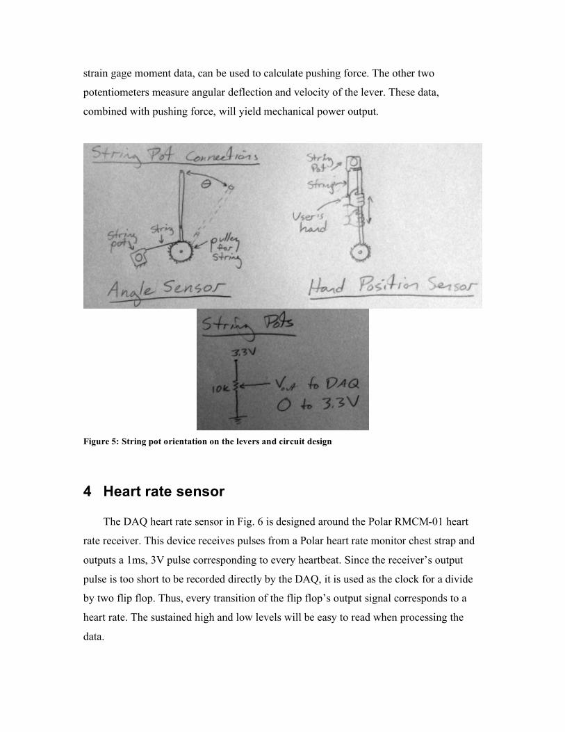
strain gage moment data, can be used to calculate pushing force. The other two
potentiometers measure angular deflection and velocity of the lever. These data,
combined with pushing force, will yield mechanical power output.
Figure 5: String pot orientation on the levers and circuit design
4 Heart rate sensor
The DAQ heart rate sensor in Fig. 6 is designed around the Polar RMCM-01 heart
rate receiver. This device receives pulses from a Polar heart rate monitor chest strap and
outputs a 1ms, 3V pulse corresponding to every heartbeat. Since the receiver’s output
pulse is too short to be recorded directly by the DAQ, it is used as the clock for a divide
by two flip flop. Thus, every transition of the flip flop’s output signal corresponds to a
heart rate. The sustained high and low levels will be easy to read when processing the
data.
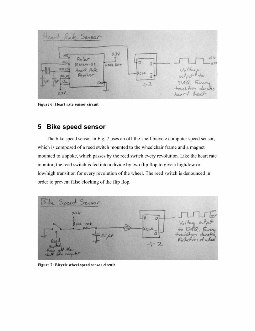
Figure 6: Heart rate sensor circuit
5 Bike speed sensor The bike speed sensor in Fig. 7 uses an off-the-shelf bicycle computer speed sensor,
which is composed of a reed switch mounted to the wheelchair frame and a magnet
mounted to a spoke, which passes by the reed switch every revolution. Like the heart rate
monitor, the reed switch is fed into a divide by two flip flop to give a high/low or
low/high transition for every revolution of the wheel. The reed switch is denounced in
order to prevent false clocking of the flip flop.
Figure 7: Bicycle wheel speed sensor circuit
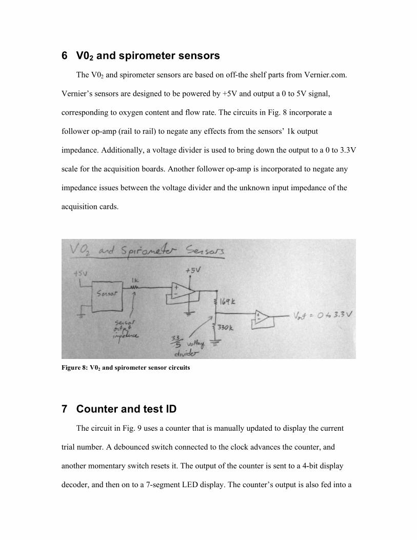
6 V02 and spirometer sensors The V02 and spirometer sensors are based on off-the shelf parts from Vernier.com.
Vernier’s sensors are designed to be powered by +5V and output a 0 to 5V signal,
corresponding to oxygen content and flow rate. The circuits in Fig. 8 incorporate a
follower op-amp (rail to rail) to negate any effects from the sensors’ 1k output
impedance. Additionally, a voltage divider is used to bring down the output to a 0 to 3.3V
scale for the acquisition boards. Another follower op-amp is incorporated to negate any
impedance issues between the voltage divider and the unknown input impedance of the
acquisition cards.
Figure 8: V02 and spirometer sensor circuits
7 Counter and test ID The circuit in Fig. 9 uses a counter that is manually updated to display the current
trial number. A debounced switch connected to the clock advances the counter, and
another momentary switch resets it. The output of the counter is sent to a 4-bit display
decoder, and then on to a 7-segment LED display. The counter’s output is also fed into a
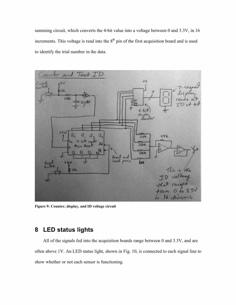
summing circuit, which converts the 4-bit value into a voltage between 0 and 3.3V, in 16
increments. This voltage is read into the 8th pin of the first acquisition board and is used
to identify the trial number in the data.
Figure 9: Counter, display, and ID voltage circuit
8 LED status lights All of the signals fed into the acquisition boards range between 0 and 3.3V, and are
often above 1V. An LED status light, shown in Fig. 10, is connected to each signal line to
show whether or not each sensor is functioning.
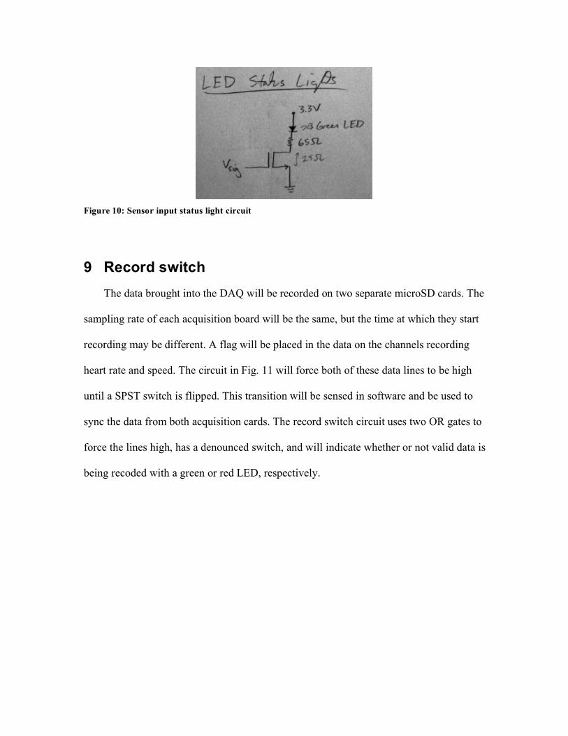
Figure 10: Sensor input status light circuit
9 Record switch The data brought into the DAQ will be recorded on two separate microSD cards. The
sampling rate of each acquisition board will be the same, but the time at which they start
recording may be different. A flag will be placed in the data on the channels recording
heart rate and speed. The circuit in Fig. 11 will force both of these data lines to be high
until a SPST switch is flipped. This transition will be sensed in software and be used to
sync the data from both acquisition cards. The record switch circuit uses two OR gates to
force the lines high, has a denounced switch, and will indicate whether or not valid data is
being recoded with a green or red LED, respectively.
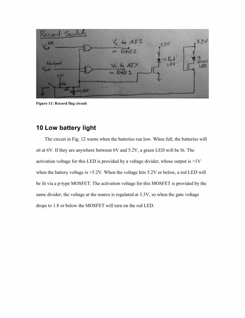
Figure 11: Record flag circuit
10 Low battery light The circuit in Fig. 12 warns when the batteries run low. When full, the batteries will
sit at 6V. If they are anywhere between 6V and 5.2V, a green LED will be lit. The
activation voltage for this LED is provided by a voltage divider, whose output is >1V
when the battery voltage is >5.2V. When the voltage hits 5.2V or below, a red LED will
be lit via a p-type MOSFET. The activation voltage for this MOSFET is provided by the
same divider; the voltage at the source is regulated at 3.3V, so when the gate voltage
drops to 1.8 or below the MOSFET will turn on the red LED.
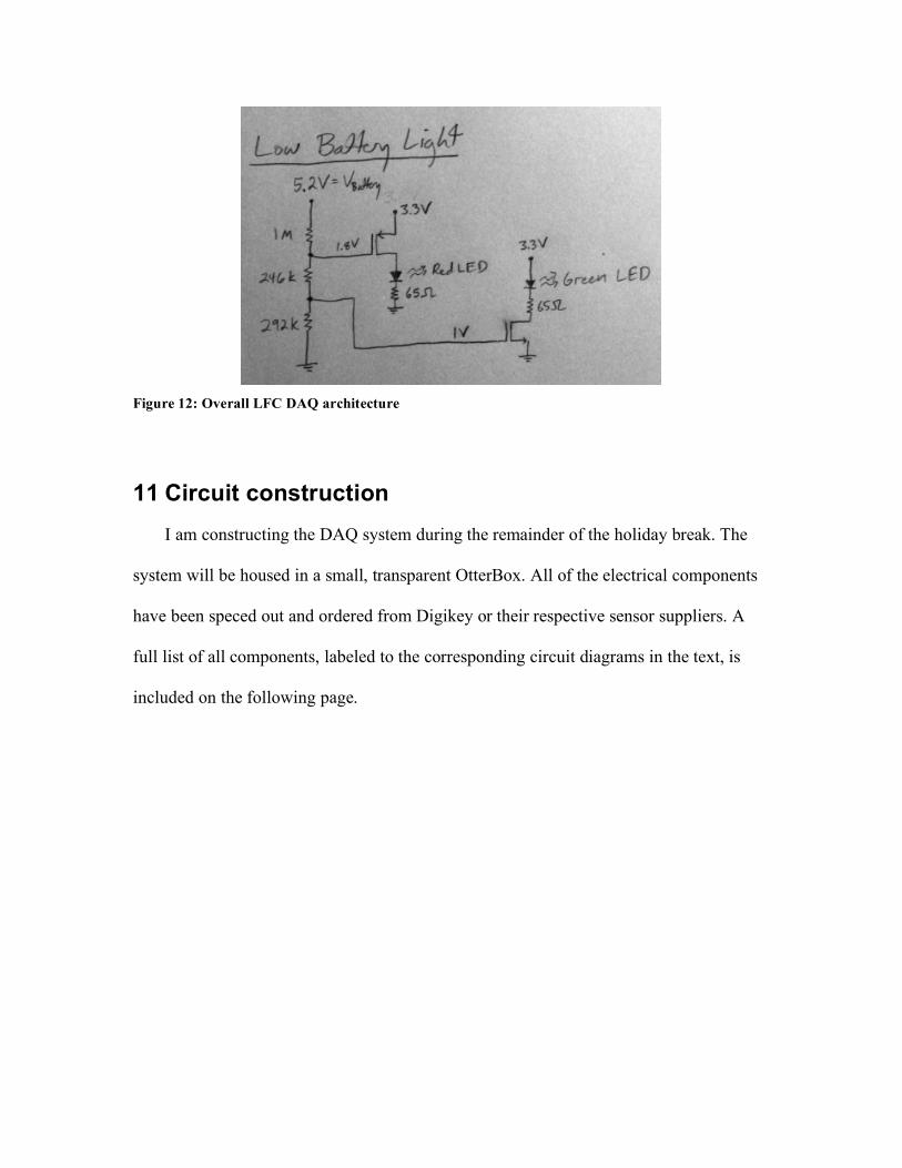
Figure 12: Overall LFC DAQ architecture
11 Circuit construction I am constructing the DAQ system during the remainder of the holiday break. The
system will be housed in a small, transparent OtterBox. All of the electrical components
have been speced out and ordered from Digikey or their respective sensor suppliers. A
full list of all components, labeled to the corresponding circuit diagrams in the text, is
included on the following page.
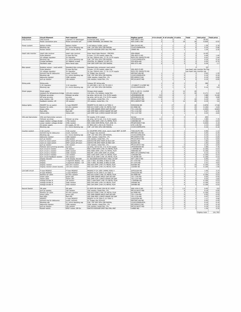
Subsystem Circuit Element Part required Description Digikey part# # in circuit # of circuits # extra Total Unit price Total priceDAQ boards DAQ boards Logmatic V2 datalogger 8-channel DAQ, 10-bit WIG-08627 (SF) 1 2 2 4 59.95
Power connection pins Power connector pin CONN TERMINAL 28-24AWG TIN 455-2148-1-ND 2 2 16 20 0.026 0.520
Power system Battery Holder Battery holder 4 AA battery holder, series SBH-341AS-ND 1 1 1 2 1.39 2.78Blocking cap 0.1 micro blocking cap CAP .1UF 50V 20% CER RADIAL C315C104M5U5TA 1 1 5 6 0.16 0.96Rocker switch SPST rocker, Off-On SWITCH ROCKER SPST BLK PNL MNT CH865-ND 1 1 1 2 1.16 2.32
Heart rate monitor Heart rate receiver Heart rate receiver Polar Heart Rate Module - RMCM01 SEN-08660 1 1 2 3 14.95Pulse detector D-type flip flop D-type, 2-5.5V supply, edge trig 296-4623-5-ND 1 1 2 3 0.48 1.443V voltage regulator 3V regulator 3V reg, 250mA max, 2.7 to 13.2V supply MCP1702-3002E/TO-ND 1 1 1 2 0.52 1.04Blocking cap 0.1 micro blocking cap CAP .1UF 50V 20% CER RADIAL C315C104M5U5TA 1 1 0 1 0.16 0.16Crystal oscillator 32.768kHZ crystal CRYSTAL 32.768KHZ 12.5PF CYL 535-9034-ND 1 1 2 3 0.25 0.75Oscillator caps 9pico farad caps CAP CER 9.0PF 50V C0G RADIAL 490-3771-ND 2 1 3 5 0.34 1.7
Bike speed Rotation sensor - reed switch Standard bike computer Standard bike computer reed switch 3 25Pulse detector D-type flip flop D-type, 2-5.5V supply, edge trig 296-4623-5-ND use heart rate monitor flip flop3V voltage regulator 3V regulator 3V reg, 250mA max, 2.7 to 13.2V supply MCP1702-3002E/TO-ND use heart rate monitor regSchmitt trig for debounce invert, Schmitt IC Trigger Hex Schmitt MM74HC14N-ND 1 1 2 3 0.45 1.35Blocking cap 0.1 micro blocking cap CAP .1UF 50V 20% CER RADIAL C315C104M5U5TA 1 1 0 1 0.16 0.16debounce resistor 100k resistor 100k resistor, metal film, 1% PPC100KYCT-ND 1 1 4 5 0.19 0.95pull up resistor 10k resistor 10k resistor, metal film, 1% PPC10.0KYCT-ND 1 1 4 5 0.19 0.95
String pots String pots Celesco 50' string pots 1 4 1 5 1803.3V regulator 3.3V regulator IC LDO REG 1.5A 3.3V TO-220-3 LT1086CT-3.3#PBF-ND 1 1 1 2 4 8Blocking cap 0.1 micro blocking cap CAP .1UF 50V 20% CER RADIAL C315C104M5U5TA 1 1 4 5 0.16 0.8
Strain gages Strain gages Omega strain gages KFG-3-120-C1-11LM2R 2 4 12 20resistors for Wheatstone bridge 120 ohm resistor 120 ohm, 1% resistor, metal film P120CACT-ND 2 4 12 20 0.171 3.42Follower op-amps follower op-amp op-amp, rail-to-rail, 3 to 15.5V supply LMC6484AIN-ND 0.5 4 1 3 3.88 11.64diff amp op-amp op-amp op-amp, rail-to-rail, 3 to 15.5V supply LMC6484AIN-ND 0.25 4 1 1 3.88 3.88amp resistor, 10k 10k resistor 10k resistor, metal film, 1% PPC10.0KYCT-ND 4 4 4 20 0.19 3.8feedback resistor, 1M 1M resistor 1M resistor, metal film, 1% PPC1.00MYCT-ND 2 4 12 20 0.19 3.8
Status lights MOSFET for on switch n-type MOSFET MOSFET N-CH 200V 0.1A TO92-3 ZVN3320A-ND 1 17 3 20 0.878 17.56Resistor for LEDs 65 ohm resistor RES 64.9 OHM 1/4W 1% METAL FILM 64.9XBK-ND 1 17 8 25 0.106 2.65Green LEDs green LED LED 3MM GREEN 4MCD GAP ON GAP 751-1104-ND 1 17 8 25 0.393 9.825Red LEDs Red LED LED 3MM RED 2.5MCD GAASP ON GAP 751-1132-ND 1 1 4 5 0.47 2.35Yellow LEDs Yellow LED LED 3MM YLW 2.5MCD GAASP ON GAP 751-1147-ND 4 1 1 5 0.53 2.65
V02 and Spirometer VO2 and Spirometer sensors 5V supply, 0-5V output Vernier 1 2 0 2 200Follower op-amps follower op-amp op-amp, rail-to-rail, 3 to 15.5V supply LMC6484AIN-ND 0.5 2 1 2 3.88 7.76Upper resistor voltage divider 170k resistor RES 169K OHM 1/4W 1% METAL FILM 169KXBK-ND 1 2 3 5 0.106 0.53Lower resistor voltage divider 330k resistor RES 330K OHM METAL FILM .25W 1% PPCQF330KCT-ND 1 2 3 5 0.636 3.185V power supply 5V supply, 6V Vin IC REG LDO 1.25A 5.0V TO220-3 576-1136-ND 1 1 2 3 2.23 6.69Blocking cap 0.1 micro blocking cap CAP .1UF 50V 20% CER RADIAL C315C104M5U5TA 1 1 0 1 0.16 0.16
Counter system 4-bit counter 4-bit counter IC COUNTER SYNC clock, async reset 4BIT 16-DIP 74AC161PC-ND 1 1 1 2 0.56 1.12Schmitt trig for debounce invert, Schmitt IC Trigger Hex Schmitt MM74HC14N-ND 1 1 0 1 0.45 0.45Blocking cap 0.1 micro blocking cap CAP .1UF 50V 20% CER RADIAL C315C104M5U5TA 1 1 0 1 0.16 0.16debounce resistor 100k resistor 100k resistor, metal film, 1% PPC100KYCT-ND 1 1 4 5 0.19 0.95pull up resistor 10k resistor 10k resistor, metal film, 1% PPC10.0KYCT-ND 1 1 4 5 0.19 0.95mom-on clock switch SPST switch off-mom SWITCH PB SPST MOM 3A BLK CAP EG2041-ND 1 1 1 2 1.83 3.66mom-on reset switch SPST switch off-mom SWITCH PB SPST MOM 3A RED CAP EG2045-ND 1 1 1 2 1.83 3.66pull up resistor 10k resistor 10k resistor, metal film, 1% PPC10.0KYCT-ND 1 1 0 5 0.19 0.95Follower and summing op-amp op-amp op-amp, rail-to-rail, 3 to 15.5V supply LMC6484AIN-ND 0.25 2 1.5 2 3.88 7.76Sum circuit 0 resistor 1M resistor RES 1.00M OHM 1/4W 1% METAL FILM 1.00MXBK-ND 1 1 4 5 0.106 0.53Sum circuit 1 resistor 500k resistor RES 499K OHM 1/4W 1% METAL FILM 499KXBK-ND 1 1 4 5 0.106 0.53Sum circuit 2 resistor 250k resistor RES MF 1/4W 249K OHM 1% AXIAL RNF1/4T1249KFRCT-ND 1 1 4 5 0.15 0.75Sum circuit 3 resistor 125 resistor RES 124K OHM 1/4W 1% METAL FILM 124KXBK-ND 1 1 4 5 0.106 0.53Sum circuit feedback resistor 44k resistor RES 44.2K OHM 1/4W 1% METAL FILM 44.2KXBK-ND 1 1 4 5 0.106 0.53Display decoder 4-bit display decoder IC DECODER/DIVDR BCD-7SEG 16-DIP 497-1364-5-ND 1 1 1 2 0.95 1.9Display 7-segment display - CC LED 7-SEG .56 SNGL S-RED CC DIR 67-1476-ND 1 1 1 2 2.31 4.62Display 7-segment display - CA LED 7-SEG .56 SNGL S-RED CA DIR 67-1475-ND 1 1 1 2 2.31 4.62Display resistor 600 ohm resistor RES 604 OHM 1/4W 1% METAL FILM 604XBK-ND 7 1 3 10 0.106 1.06Display resistor (lower bound) 150 ohm resistor RES 150 OHM 1/4W 1% METAL FILM 150XBK-ND 7 1 3 10 0.106 1.06
Low batt circuit P-type MOSFET P-Type MOSFET MOSFET P-CH 100V 140MA TO92-3 ZVP3310A-ND 1 1 2 3 1.05 3.15N-type MOSFET n-type MOSFET MOSFET N-CH 200V 0.1A TO92-3 ZVN3320A-ND 1 1 1 2 1.17 2.34Resistor for LEDs 65 ohm resistor RES 64.9 OHM 1/4W 1% METAL FILM 64.9XBK-ND 2 1 3 5 0.106 0.53Green LEDs green LED LED 3MM GREEN 4MCD GAP ON GAP 751-1104-ND 1 1 0 1 0.55 0.55Yellow LEDs Yellow LED LED 3MM YLW 2.5MCD GAASP ON GAP 751-1147-ND 4 1 1 5 0.53 2.65Voltage divider R 1M resistor RES 1.00M OHM 1/4W 1% METAL FILM 1.00MXBK-ND 1 1 4 5 0.106 0.53Voltage divider R 246k resistor RES 249 OHM 1/4W 1% METAL FILM 249XBK-ND 1 1 4 5 0.106 0.53Voltage divider R 292k resistor RES 294 OHM 1/4W 1% METAL FILM 294XBK-ND 1 1 4 5 0.106 0.53
Record Switch OR gate OR gate IC GATE OR QUAD 2IN HS SI 14DIP 568-1434-5-ND 0.5 1 1.5 2 0.45 0.9pull up resistor 10k resistor 10k resistor, metal film, 1% PPC10.0KYCT-ND 1 1 4 5 0.19 0.95Resistor for LEDs 65 ohm resistor RES 64.9 OHM 1/4W 1% METAL FILM 64.9XBK-ND 2 1 3 5 0.106 0.53Green LEDs green LED LED 3MM GREEN 4MCD GAP ON GAP 751-1104-ND 1 1 0 1 0.55 0.55Red LEDs Red LED LED 3MM RED 2.5MCD GAASP ON GAP 751-1132-ND 1 1 0 1 0.47 0.47MOSFET n-type MOSFET MOSFET N-CH 200V 0.1A TO92-3 ZVN3320A-ND 2 1 2 4 1.17 4.68Schmitt trig for debounce invert, Schmitt IC Trigger Hex Schmitt MM74HC14N-ND 1 1 0 1 0.45 0.45Blocking cap 0.1 micro blocking cap CAP .1UF 50V 20% CER RADIAL C315C104M5U5TA 1 1 0 1 0.16 0.16debounce resistor 100k resistor 100k resistor, metal film, 1% PPC100KYCT-ND 1 1 0 1 0.19 0.19pull up resistor 10k resistor 10k resistor, metal film, 1% PPC10.0KYCT-ND 1 1 0 1 0.19 0.19Rocker switch SPST rocker, Off-On SWITCH ROCKER SPST BLK PNL MNT CH865-ND 1 1 1 2 1.16 2.32
Digikey total 161.765