lever butterfly valves válvulas de mariposa...
TRANSCRIPT

Range• Sizes from 2˝-10˝
Standards• ANSI/ASTM, ISO/DIN, British Standard, JIS
Working Pressure• At 73°F: 2˝-5˝ 150 psi
6˝-10˝ 115 psi
Features• PVC body & disc• PVC coated, double O-Ring sealed, non-wetted
1-piece shaft (316SS available)• 10-position elasticized aluminum lever handle
(available throughout the full range of sizes).• Plasticized aluminum top plate with full position
indication and built-in stops• EPDM/Viton® self-sealing gaskets• Gear operators; electric/pneumatic actuation;
stainless steel stem extensions available• Low torque design• Silicone-free construction• Excellent flow characteristics• Superior mechanical strength• Ideally suited for flow control using minimal
piping space• Competitive price• Industrial series valves have SSTL shafts• Standard series valves have 2 zinc plated
steel shafts• Stem extensions available–contact Hayward
for details
Medidas• Rango desde 2˝ hasta 10˝
Standards• ANSI/ASTM, ISO/DIN, British Standard, JIS
Presión de Servicio• A 73°F: 2˝-5˝ 150 psi
6˝-10˝ 115 psi
Características• Cuerpo y compuerta en PVC• Vástago de una sola pieza de acero al carbón
recubierto de PVC, totalmente estanco (disponible también en AISI 316)
• Palanca de aluminio plastificada de 10 posiciones (disponible para toda la gama de medidas)
• Conjunto divisor de aluminio plastificado con indicación visual de posición y topes incorporados
• Sello en EPDM a Viton®
• Reductor manual; actuación eléctrica/neumática;extensiones del vástago en acero inoxidable disponibles
• Bajo par de maniobra• Construcción libre de silicona• Excelentes características de conducción• Resistencia mecánica superior• Ideal para el control del fluido usando
poco espacio• Precio competitivo
Parts/Despiece1. Body 1. Cuerpo2. Valve Disc 2. Compuerta3. Rubber Seal 3. Junta compuerta4. Shaft 4. Vástago5. O-Ring Seal 5. Junta vástago6. Top Bearing 6. Casquillo guía7. Throttle Plate 7. Conjunto divisor8. Lever-lock 8. Gatillo de la palanca9. Handle 9. Palanca
*Screw set in stainless steel *Tomilleriá en acero inoxidable
Lever Butterfly ValvesVálvulas de mariposamanuales
16
2˝- 8˝
4
8
7
1
2
3
9
5
5
5
5
6
87
2
1
4
53
1
9
5
PVC
PE
EPDM/Viton®
6
21
4
53
Stainless steel (Industrial) Zinc plated steel (Standard)
87 Aluminum/Aluminio9
10˝

10˝
7
5
5
5
5
1
2
3
4
2˝ - 8˝
7
65
5
1
2
3
4
PVC
PE
EPDM/Viton®
6
21
4
53
Stainless steel (Industrial) Zinc plated steel (Standard)
7 Aluminum / Aluminio
Range• Sizes from 2˝-10˝
Standards• ANSI/ASTM, ISO/DIN, British Standard, JIS
Working Pressure• At 73°F: 2˝-5˝ 150 psi
6˝-10˝ 115 psi
Features• PVC body & disc• PVC coated, double O-Ring sealed,
non-wetted 1-piece shaft (316SS available)• External open/close adjustment controls• EPDM/Viton® self-sealing gaskets• Lever handle; electric/pneumatic actuation;
stainless steel stem extensions available• Low torque design• Silicone-free construction• Excellent flow characteristics• Superior mechanical strength• Ideally suited for flow control using minimal
piping space• Competitive price
Medidas• Medidas desde 2˝ hasta 10˝
Standards• ANSI/ASTM, ISO/DIN, British Standard, JIS
Presión de Servicio• A 73°F: 2˝-5˝ 150 psi
6˝-10˝ 115 psi
Características• Cuerpo y compuerta en PVC• Vástago de una sola pieza de acero al carbón
recubidierto de PVC, totalmente estanco (disponible también en AISI 316)
• Ajuste de controles de apertura externos• Sello en EPDM o Viton®
• Palanca; actuación eléctrica/neumática;extensiones del vástago en acero inoxidable disponibles
• Bajo par de maniobra• Construcción libre de silicona• Excelentes características de conducción• Resistencia mecánica superior• Ideal para el conrol del fluido usando
poco espacio• Precio competitivo
1. Body 1. Cuerpo2. Valve Disc 2. Compuerta3. Rubber Seal 3. Junta compuerta4. Shaft 4. Vástago5. O-Ring Seal 5. Junta vástago6. Top Bearing 6. Casquillo guía7. Gear Box 7. Reductor manual
Parts/Despiece
With Hand Wheel Gear BoxCon Reductor Manual
in in in in
2˝- 21/2˝ 7.56 6.30 10.43 9.02
3˝ 8.94 6.30 11.81 10.35
4˝ 10.67 6.30 13.54 12.09
5˝ 10.69 6.30 14.57 13.11
6˝ 12.87 6.30 15.75 14.29
8˝ 15.75 12.20 18.62 17.17
10˝ 17.72 12.20 19.29 20.47
D1C1ASize E
17
A
E
C1
D1

2
1
3
4
Electric Actuator/Actuador Electrico
Parts Despiece1. Butterfly valve 1. Válvula de mariposa2. Electric actuator 2. Actuador eléctrico3. Actuator valve coupling 3. Casquillo unión actuador-válvula4. Mounting clamp 4. Brida de unión
Actuated ValvesVálvulas Actuadas
18
EJM130S2T
Wiring DiagramEJM2S2T/EJM3S2T
EJM35S2TEJM8S2T/EJM13S2T
Range• 1/2˝ - 4˝ (20 mm-110 mm) Working Pressure• At 73°F: 1/2˝ - 2˝ (20 mm-63 mm) 240 psi
21/2˝- 4˝ (75 mm-110 mm) 150 psiFeaturesElectric Actuator• 2 Auxiliary limit switches • Heater and thermostat • NEMA 4/4X Housing • Position indication • Manual override • Self locking gear train• Permanently lubricated • Thermal overload protection• CE and CSA approved • ISO 5211 mounting base
Medidas• 1/2˝ - 4˝ (20 mm-110 mm) Presión de Servicio• A 73°F: 1/2˝ - 2˝ (20 mm-63 mm) 240 psi
21/2˝- 4˝ (75 mm-110 mm) 150 psiCaracteristicasActuador eléctrico:• Interruptores de limite auxiliar• Calentador y termostato • Cajas NEMA 4/4X• Indicador de posición • Operación manual• Tren de engranaje • CE y CSA aprobado• Lubricado permanentemente• Protección térmica de sobrecarga
Medicas• 1/2˝ - 4˝ (20 mm-110 mm) Pressão de Servico• A 73°F: 1/2˝- 2˝ (20 mm-63 mm) 240 psi
21/2˝- 4˝ (75 mm-110 mm) 150 psiCaracterísticasActuador eléctrico:• Interruptores de limite auxiliar• Termostato e aquecedor • Caixa NEMA 4/4X• Indicador de posição • Operação manual• Fecho automático de engrenagem• Sobrecarrega protegida Térmicamente• Aprovado en CE e CSA• Permanentemente lubrificado
A B C D E F
2˝-21/2˝ 8.56 6.5 5.33 1.89 4.92/5.71 0.71 x 0.16
3˝ 9.94 7.87 5.96 2.09 6.30/6.65 0.71 x 0.31
4˝ 11.67 9.02 7.14 2.36 7.03/7.48 0.71 x 0.31
5˝ 12.69 9.84 7.77 0.6 7.48/8.27 0.71 x 0.31
6˝ 13.87 11.22 8.28 2.83 3.45 0.87 x 0.31
8˝ 16.75 13.39 10.06 2.87 10.63/11.61 0.87 x 0.31
10˝ 18.72 12.56 10.84 4.25 13.58/14.85 0.94 x 0.47
A
E
E
C
B D
F

Pneumatic Actuator/Actuador Neumatico
Parts Despiece1. Butterfly valve 1. Válvula de mariposa2. Pneumatic actuator 2. Actuador neumatico3. Coupling 3. Casquillo unión4. Mounting clamp 4. Brida Fijación
1
4
3 2
19
Actuated ValvesVálvulas Actuadas
A B C D E F
2˝-21/2˝ 8.56 6.5 5.33 1.89 4.92/5.71 0.71 x 0.16
3˝ 9.94 7.87 5.96 2.09 6.30/6.65 0.71 x 0.31
4˝ 11.67 9.02 7.14 2.36 7.03/7.48 0.71 x 0.31
5˝ 12.69 9.84 7.77 0.6 7.48/8.27 0.71 x 0.31
6˝ 13.87 11.22 8.28 2.83 3.45 0.87 x 0.31
8˝ 16.75 13.39 10.06 2.87 10.63/11.61 0.87 x 0.31
10˝ 18.72 12.56 10.84 4.25 13.58/14.85 0.94 x 0.47
DimensionsPCD Series Pneumatic Actuators
(Double Acting)
Model A B C D E ISO 5211 AirMount Consumption
inch inch inch inch inch inch CU. IN.
PCD 15 3.39 3.85 3.50 0.53 0.35 F05 5.5(1.97)
PCD 20 4.03 4.60 3.96 0.59 0.43 F05 9.2(1.97)
PCD 25 5.24 5.79 4.61 0.77 0.55 F07 20(2.76)
PCD 30 5.94 6.64 5.37 0.87 0.67 F07 33(2.76)
PCD 35 7.15 7.94 6.10 1.02 0.87 F10 49(4.02)
PCD 45 8.70 - 7.64 1.30 1.06 F12 81(4.92)
PCD 60 11.22 - 9.76 1.69 1.42 F14 195(5.51)
PCD 75 13.46 - 11.81 1.69 1.42 F16 351(6.50)
Series PCS - Air to Spring/Fail SafeSeries PCD - Air to Air/Double Acting
C
D
A
B
C
B
A
A
LP.
C.D
.
DimensionsPCS Series Pneumatic Actuators
(Spring Return)
Model A B C E ISO 5211 AirMount Consumption
inch inch inch inch inch CU. IN.
PCS 15 4.31 3.50 0.53 0.35 F05 4.3(1.97)
PCS 20 5.17 3.96 0.59 0.43 F05 7.3(1.97)
PCS 25 6.34 4.61 0.77 0.55 F07 15(2.76)
PCS 30 7.33 5.37 0.87 0.67 F07 27(2.76)
PCS 35 8.74 6.10 1.02 0.87 F10 45(4.02)
PCS 45 10.59 7.64 1.30 1.06 F12 81(4.92)
PCS 60 14.17 9.76 1.69 1.42 F14 195(5.51)
PCS 75 17.20 11.81 1.69 1.42 F16 351(6.50)
Torque Output @ 80 psiModel Torque (in-lb) Model Torque (in-lb)
PCD 15 172 PCD 35 1848
PCD 20 311 PCD 45 3622
PCD 25 639 PCD 60 8585
PCD 30 1052 PCD 75 15856
Torque Output @ 80 psi - EndingModel Torque (in-lb) Model Torque (in-lb)
PCS 15 61 PCS 35 607
PCS 20 85 PCS 45 1218
PCS 25 217 PCS 60 2857
PCS 30 345 PCS 75 5166
Side View
Top View
E
E
Output Shaft
Side View
Top View
E
E
Output Shaft
Range• 1/2˝ - 4˝ (20 mm-110 mm) Working Pressure• At 73°F: 1/2˝ - 2˝ (20 mm-63 mm) 240 psi
21/2˝- 4˝ (75 mm-110 mm) 150 psiFeaturesPneumatic Actuator• Four-piston rack and pinion design• Manual override • Compact, lightweight • Position indicator• Namur style solenoid mounting• Adjustable travel stops • ISO 5211 mounting base
Medidas• 1/2˝ - 4˝ (20 mm-110 mm) Presión de Servicio• A 73°F: 1/2˝ - 2˝ (20 mm-63 mm) 240 psi
21/2˝- 4˝ (75 mm-110 mm) 150 psiCaracteristicasActuador Neumático:• Caja de cuatro pistones y diseño de piñón• Operación manual • Compacta y ligera• Montura Namur para solenoides• Parada ajustable • Base de Montura ISO 511
Medicas• 1/2˝ - 4˝ (20 mm-110 mm) Pressão de Servico• A 73°F: 1/2˝- 2˝ (20 mm-63 mm) 240 psi
21/2˝- 4˝ (75 mm-110 mm) 150 psiCaracterísticasActuador Pneumático:• Caixa de quatro pistões y desenho de êmbolo• Operação manual • Compacta e pêso-leve• Indicador de posição • Parada ajustable• Base de Montura ISO 511
A
E
E
C
B D
F
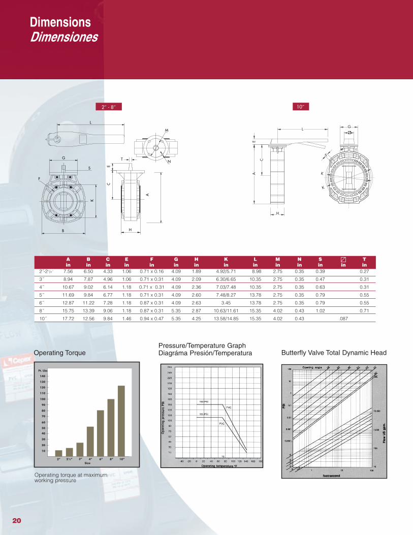
Butterfly Valve Total Dynamic Head
Operating torque at maximum working pressure
Operating Torque
A B C E F G H K L M N S Tin in in in in in in in in in in in in in
2˝-21/2˝ 7.56 6.50 4.33 1.06 0.71 x 0.16 4.09 1.89 4.92/5.71 8.98 2.75 0.35 0.39 0.27
3˝ 8.94 7.87 4.96 1.06 0.71 x 0.31 4.09 2.09 6.30/6.65 10.35 2.75 0.35 0.47 0.31
4˝ 10.67 9.02 6.14 1.18 0.71 x 0.31 4.09 2.36 7.03/7.48 10.35 2.75 0.35 0.63 0.31
5˝ 11.69 9.84 6.77 1.18 0.71 x 0.31 4.09 2.60 7.48/8.27 13.78 2.75 0.35 0.79 0.55
6˝ 12.87 11.22 7.28 1.18 0.87 x 0.31 4.09 2.63 3.45 13.78 2.75 0.35 0.79 0.55
8˝ 15.75 13.39 9.06 1.18 0.87 x 0.31 5.35 2.87 10.63/11.61 15.35 4.02 0.43 1.02 0.71
10˝ 17.72 12.56 9.84 1.46 0.94 x 0.47 5.35 4.25 13.58/14.85 15.35 4.02 0.43 .087
Pressure/Temperature GraphDiagráma Presión/Temperatura
DimensionsDimensiones
2˝ - 8˝ 10˝
S
N
M
EC
A
L
G
F
K
H
T
L
K
K
F
H
AE
C
G
B
20
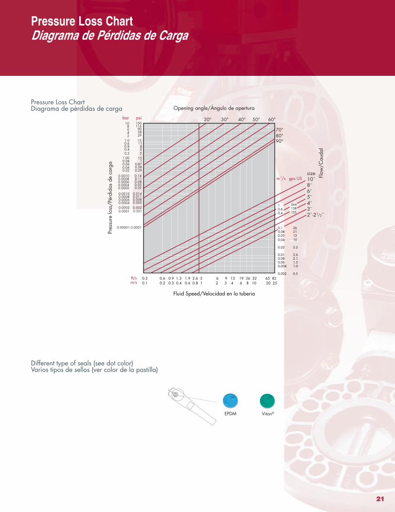
Pressure Loss ChartDiagrama de pérdidas de carga
EPDM Viton®
20° 30° 40° 50° 60°
70°80°90°
size
86543
10˝˝˝˝˝˝
2˝-21/2˝
0,04
0,02
0,010,080,060,004
0,002
0,10,080,05
Fluid Speed/Velocidad en la tuberia
Pres
surelo
ss/P
érdi
das
deca
rga
Flow/C
audal
10,60,4
bar10 8
64
1.00.60.80.4
2
1.000.080.060.040.02
0.00100.00080.00060.0004
0.00100.00080.00060.00040.0002
0.00001
0,2
0.00020.0001
2 3 4 6 8 10 20 250.1 0.2 0.3 0.4 0.6 0.8 1m/s
Opening angle/Ángulo de apertura
psi150
116 90 58
151185
29
151
0.870.580.29
0.0140.0110.0080.005
0.140.110.080.050.02
0.0001
2
0.0020.001
6 9 13 19 26 32 65 820.3 0.6 0.9 1.3 1.9 2.6 3ft/s
m /s3
264158105
10
5.2
2.62.11.51.0
0.5
262113
gps US
Different type of seals (see dot color)Varios tipos de sellos (ver color de la pastilla)
Pressure Loss ChartDiagrama de Pérdidas de Carga
21

Technical Data
M3/hr = 3.671 I.G.M.I.G.P.M. = 41.14 Barrels/Day
T.P.H. = 3.74 I.G.M.I.G.P.M. = 1.2 U.S. G.P.M.I.G.P.M. = 4.54 Liters/Min
LITER/MIN = 0.22 I.G.P.M.U.S. G.P.M. = 0.833 I.G.P.M.
Barrel = 35 Imp. GallonsBarrel = 42 U.S. Gallons
FLOW CONVERSIONFACTORS
FLOW VELOCITY CONVERSION FACTORS
Velocity in Ft/Sec = GPM x 0.4085ID2 in Inches
To Obtain U.S. Imperial U.S. U.S. Pound U.S. Cubic U.S. Cubic Liter CubicMultiply By Gallon Gallon Pint Water Foot Inch MeterU.S. Gallon 1 0.833 8.0 8.337 0.13368 231.0 3.78533 0.003785Imperial Gallon 1.2009 1 9.60752 10.0 0.16054 277.42 4.54596 0.004546U.S. Pint 0.125 0.1041 1 1.042 0.01671 28.875 0.473168 0.000473
U.S. Pound Water 0.11995 0.1 0.9596 1 0.016035 27.708 0.45405 0.00454U.S. Cubic Foot 7.48052 6.22888 59.8442 62.365 1 1728.0 28.31702 0.028317U.S. Cubic Inch 0.004329 0.00361 0.034632 0.03609 0.0005787 1 0.016387 0.0000164
Liter 0.2641779 0.2199756 2.113423 2.202 0.0353154 61.02509 1 0.001000Cubic Meter 264.170 219.969 2113.34 2202 35.31446 61023.38 999.972 1
To convert from net unit to another, locate the starting unit in the left column. Multiply by the factor shown horizontally to the right under the desired unit.
Volume Conversion Factors
Pressure Conversion Factors
To Obtain Pound Round Atmosphere Kilogram Inch Foot Inch mm BarMultiply By Sq. In. Sq. Ft. Sq. Cm. Water Water Mercury MercuryPounds/Sq. In. 1 144.0 0.068046 0.070307 27.7276 2.3106 2.0360 51.7150 0.06895Pounds/Sq. Ft. 0.0069545 1 0.000473 0.000488 0.1926 0.01605 0.014139 0.35913 0.00047Atmosphere 14.696 2116.22 1 1.0332 407.484 33.9570 29.921 760.0 1.01325
Kilogram/Sq. Cm. 14.2233 2048.16 0.96784 1 394.27 32.864 28.959 735.558 0.9807Inch Water 0.03607 5.194 0.002454 0.00254 1 0.08333 0.0734 1.865 0.00249Foot Water 0.43278 62.3205 0.029449 0.03043 12.0 1 0.8811 22.381 0.02984
Inch Mercury 0.49115 70.726 0.033421 0.03453 13.617 1.1349 1 25.40 0.03386mm Mercury 0.019337 2.7845 0.0013158 0.0013595 0.5361 0.04468 0.03937 1 0.00133Bar 14.5038 2088.55 0.98692 1.0197 33.51 402.1 29.53 750.0 1
To convert from one unit to another, locate the starting unit in the left hand column. Multiply by the factor shown horizontally to the right under the desired unit.
22