levels 7 and possibly up to level 9 are accomplished by
TRANSCRIPT

conveyor route is performed in order from beginning to
end, with delays sufficient enough for each conveyor to
be emptied. In the case of the rail loadout facility,
this also includes the chute up and down control, and
the discharge of coal into the railway trucks.
Levels 7 and possibly up to level 9 are accomplished by
the supervisory <3'J 235/48K PLC, [30, 31]. This
comprises a colour ri';U interface and operator keyboard
in the main control substation. Menu-driven route
selection, starting and stopping can be done from this
interface. All alarms occurring in the control PLC's are
sent back to the supervisory for indication on the
colour VDU for appropriate operator fault recovery.
The management information system is implemented with
the GEM 80 235 BASIC language PLC, [30, 31]. This
comprises level 10 and above. This is sent data from the
supervisory and production information and daignostics
are available from this on a serial printer.
In the event of both A and B stream control PLC failing,
each control cubicle includes manual start and stop
control psuhbuttons. This is ut;ed only if both A and B
streams of the system can not function. All three
stackers can be used with either A or B stream conveyor
systems.
The two streams of conveyors allow that ro redundant
conveyors are necessary because the projected coal
requirements of the power station are never to exceed
what either one of the streams can convey.
Case Studies76

5.2.4 Case Study Evaluation
The application of the PLC's to this plant was
successful due to the strict heirarchical implementation
of PLC's in a distributed control environment, and the
partitioning of functional areas. This allowed
sufficient memory capacity in each controlling PLC. It
also afforded an effective operator interface, and
comprehensive digital alarm display and plant mimic and
status displays.
It is evident that the distributed heirarchical computer
control of this application has caused a simple fault
detection and recovery strategy to be affected. This
assumes that an operator and the maintenance personnel
can repair the fault quickly, and get the desired routes
running. Thus, the fault recovery includes the operator
as a functional part of the control system.
It is possible that the system is not truly failsafe as
there is no redundancy of PLC's and/or serial links for
either streams at any part of the system. Also, software
functions in any of the controlling PLC's cannot be
reconfigured and controlled from any other of the system
PLC. The causes of this are the following
Case Studies
(1) The excessive cost of all the redundant PLC's and
serial links needed, and the supposed waste of
idle computing power.
(2) The large software " headache " which would be
caused by trying to implement a redundancy system on
each stream.
(3) A large design effort requiring manpower, equipment
and extra budget would have been necessary, and was
not available.


Backward Forward
Recovery Recovery
FIGURE 5.2 UNPLANNED SHUTDOWN FAULT RECOVERY SCHEMATIC
Case Studies 79
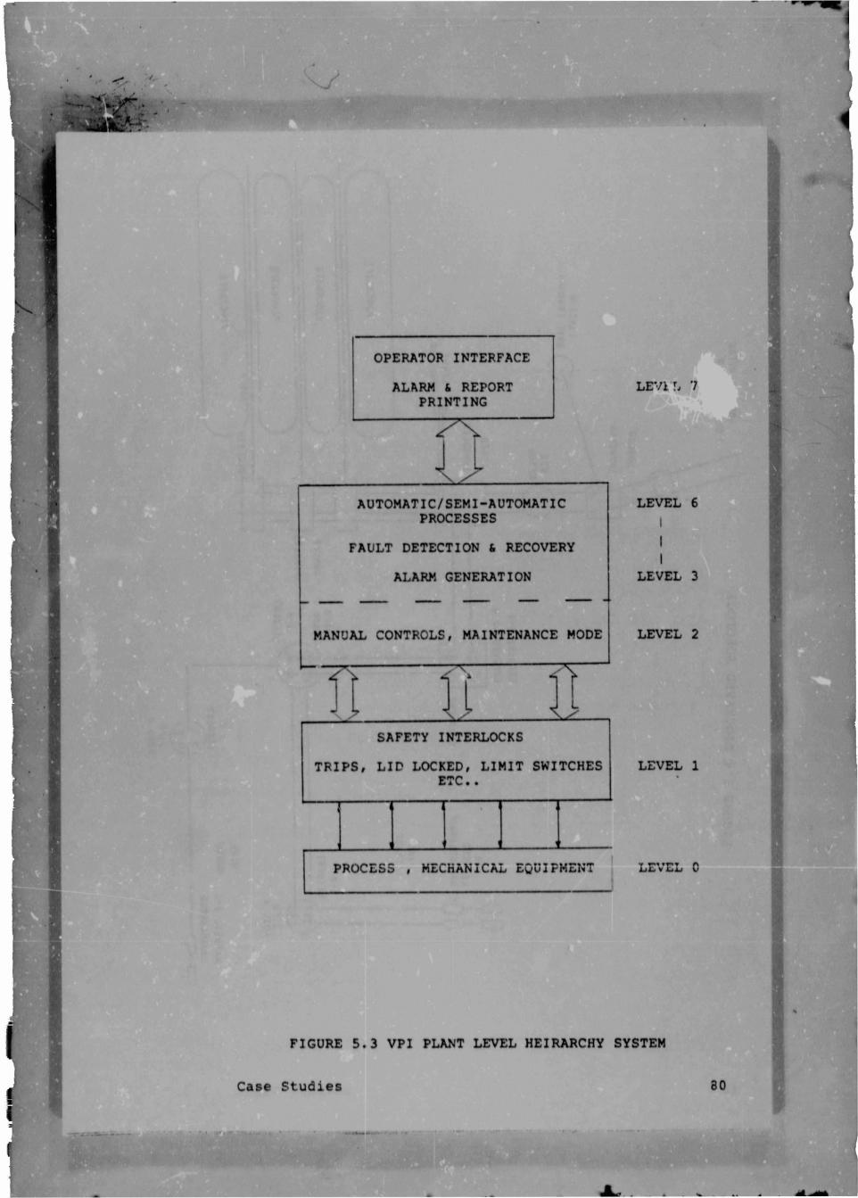
OPERATOR INTERFACE
ALARM (. REPORT
PRINTING
AUTOMATIC/SEMI-AUTOMATIC
PROCESSES
FAULT DETECTION 6 RECOVERY
ALARM GENERATION
MANUAL CONTROLS, MAINTENANCE MODE
SAFETY INTERLOCKS
TRIPS, LID LOCKED, LIMIT SWITCHES
ETC. .
PROCESS , MECHANICAL EQUIPMENT
FIGURE 5.3 VPI PLANT LEVEL HEIRARCHY SYSTEM
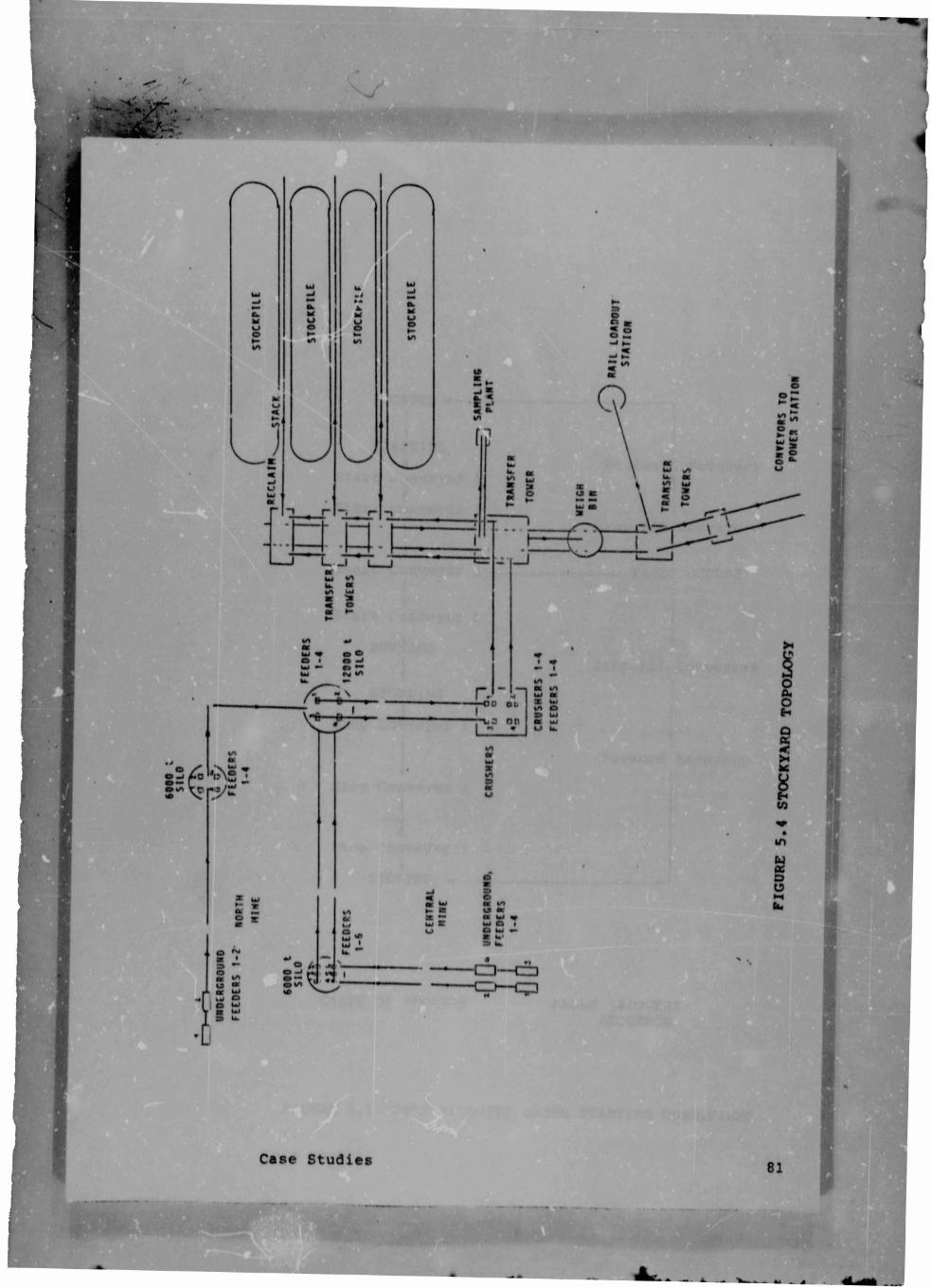
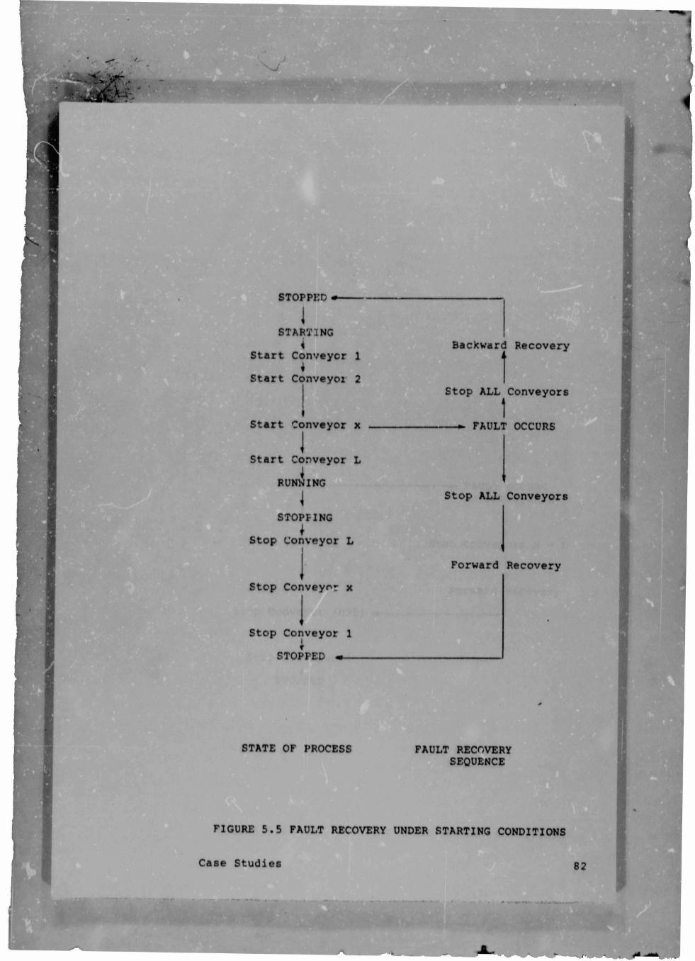
FIGURE 5.5 FAULT RECOVERY UNDER STARTING CONDITIONS
Case Studies
STOPPED -----
JSTARTING
i
Start Conveyer 1
*
Start Conveyoz 2
Start Conveyor x
I
Start Conveyor L
RUNNING
STOPFING
I
Stop Conveyor L
Stop Conveyor x
Stop Conveyor 1
STOPPED m—
STATE OF PROCESS
Backward Recovery
i >
Stop ALL Conveyors
1
--» FAULT OCCURS
Stop ALL Conveyors
Forward Recovery
FAULT RECOVERY
SEQUENCE

'
.
Stop Conveyor L
Stop Conveyor x
Stop Conveyor (x-1)
Stop Conveyor 1
*
STOPPED
STATE OF PROCESS
FIGURE 5.6 FAULT RECOVERY UNDER RJNNING CONDITIONS
^ase Studies
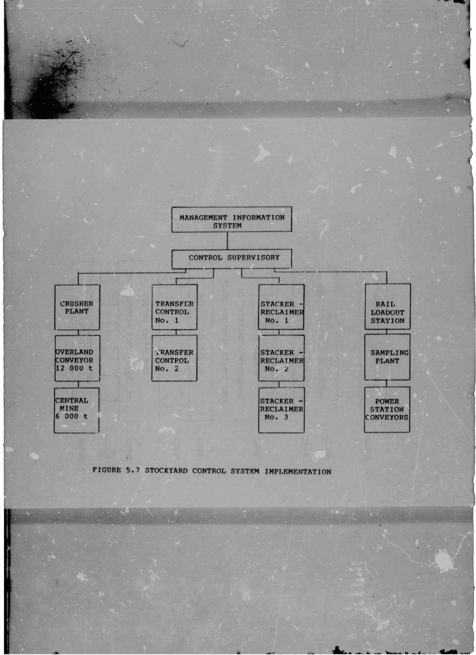
M A N A G E M E N T I N F O R M A T I O N
S Y S T E M
C O N T R O L S U P E R V I S O R Y
-----C
CRUSHER
PLANT
TRANSFER
CONTROL
NO. 1
STACKER -
RECLAIMER
No. 1
RAIL
LOADOUT
STATION
....I .... 1 1
OVERLAND
CONVEYOR
12 000 t
TRANSFER
CONTROL
No. 2
STACKER -
RECLAIMER
No. 2
SAMPLING
PLANT
r ■ 1 ...._L.
CENTRAL STACKER - POWER
MINE RECLAIMER STATION
6 000 t No. 3 CONVEYORS
FIGURE 5.7 STOCKYARD CONTROL SYSTEM IMPLEMENTATION

MANAGEMENT INFORMATION
SYSTEM
SUPERVISORY
MENU SELECTION OF ROUTES
MIMIC DISPLAYS AND ALARMS
ALARM GENERATION AND
ROUTE SELECT
DISTRIBUTED CONTROLLERS
ROUTE SEQUENCE STARTS/STOPS
MANUAL START/STOP
? T f T
H __________V
SAFETY INTERLOCKS
TRIPS,STOPS, STOP WIRES, ETC,
CONVEYORS, FLOPPER GATES &
DRIVES
LEVEL 10+
LEVEL 9
LEVEL 7
LEVEL 6
I
LEVEL 3
LEVEL 2
LEVEL 1
LEVEL 0
FIGURE 5.8 STOCKYARD CONTROL HEIRARCHY
Case Studies

Fault detection was detailed in r ion 2. In digital
systems this involves detectii ifferences in the
control environment and the cont,. which is required,
ie. inputs and outputs must be matched. Simple logic can
be included in the computer controllers to do pattern
recognition and "template matching" to detect faulty
devices. Analogue systems require a more sophisticated
fault detection scheme involving high and low limits,
rate measuring and detecting. and deviation analysis. A
variety of models were discussed in section 2.1 . All
these considerations can be included in the modelling of
the process before implementation, and in the computer
controllers for alarm detection and correction, ie.
fault detection and recovery.
Fault analysis using fault-trees was detailed in section
2.3 . This involves the design of the fault detection
and diagnosis system and analysing for all possible
faults. A general fault is determined as the top event
of the fault-tree. All system and device failures which
can cause the top event are combined in a branch type
network to form the fault-tree. This can include digital
device checks, eg. pump tripped, and analogue checks,
eg. water temperature too low, flow rate limit exceeded,
etc. . The use of an expert system as part of a control
system implementation was also detailed, viz. APEX 3.
This represented a way to» " computerise " a fault-tree.
These models and the fault tree analysis methods are not
included in the control systems. The methods are used in
the design stage to finalise all faults that need to be
detected and the failures for which recovery must be
implemented.
Discussion and Conclusions 86
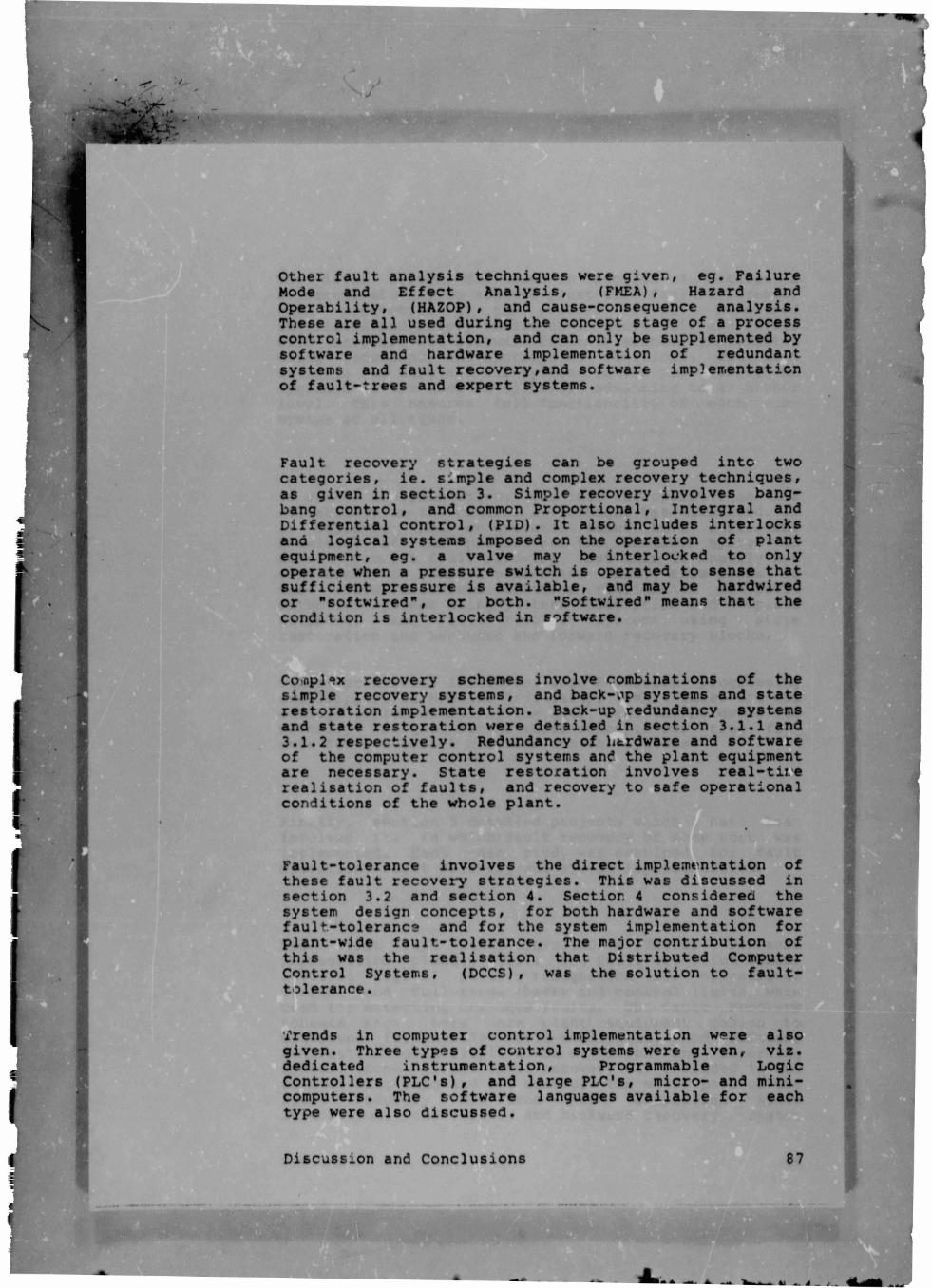
Other fault analysis techniques were given, eg. Failure
Mode and Effect Analysis, (FMEA), Hazard and
Operability, (HAZOP), and cause-consequence analysis.
These are all used during the concept stage of a process
control implementation, and can only be supplemented by
software and hardware implementation of redundant
systems and fault recovery,and software implementation
of fault-trees and expert systems.
Fault recovery strategies can be grouped into two
categories, ie. simple and complex recovery techniques,
as given in section 3. Simple recovery involves bang-
bang control, and common Proportional, Intergral and
Differential control, (PID). It also includes interlocks
and logical systems imposed on the operation of plant
equipment, eg. a valve may be interlocked to only
operate when a pressure switch is operated to sense that
sufficient pressure is available, and may be hardwired
or "softwired", or both. "Softwired" means that the
condition is interlocked in software.
Co>opl*?x recovery schemes involve combinations of the
simple recovery systems, and back-^p systems and state
restoration implementation. Back-up redundancy systems
and state restoration were detailed in section 3.1.1 and
3.1.2 respectively. Redundancy of litrdware and software
of the computer control systems and the plant equipment
are necessary. State restoration involves real-tii.e
realisation of faults, and recovery to safe operational
conditions of the whole plant.
Fault-tolerance involves the direct implemt'ntation of
these fault recovery strategies. This was discussed in
section 3.2 and section 4. Section 4 considered the
system design concepts, for both hardware and software
fault-tolerance and for the system implementation for
plant-wjde fault-tolerance. The major contribution of
this was the realisation that Distributed Computer
Control Systems, (DCCS) , was the solution to fault-
tolerance .
Trends in computer control implementation w^re also
given. Three types of control systems were given, viz.
dedicated instrumentation, Programmable Logic
Controllers (PLC's) , and large PLC's, micro- and mini
computers. The software languages available for each
type were also discussed.
— 4 _ v..
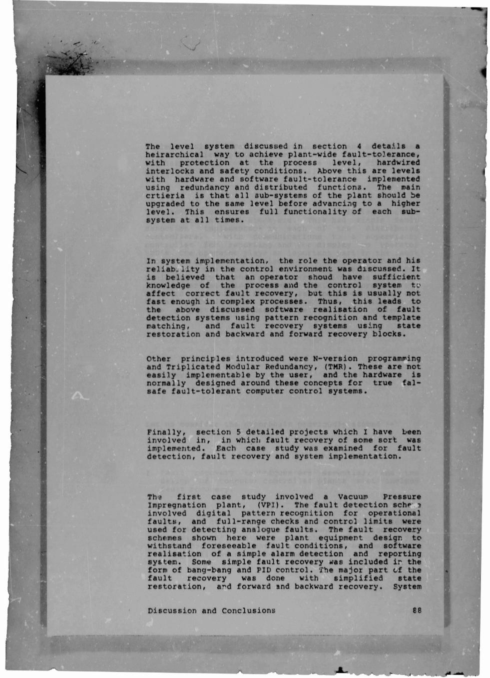
The level system discussed in section 4 details a
heirarchical way to achieve plant-wide fault-to3erance,
with protection at the process level, hardwired
interlocks and safety conditions. Above this are levels
with hardware and software fault-tolerance implemented
using redundancy and distributed functions. The main
crtieria is that all sub-systems of the plant should be
upgraded to the same level before advancing to a higher
level. This ensures full functionality of each sub
system at all times.
In system implementation, the role the operator and his
reliability in the control environment was discussed. It
is believed that an operator shoud have sufficient
knowledge of the process and the control system to
affect correct fault recovery, but this is usually not
fast enough in complex processes. Thus, this leads to
the above discussed software realisation of fault
detection systems using pattern recognition and template
matching, and fault recovery systems using state
restoration and backward and forward recovery blocks.
Other principles introduced were N-version programming
and Triplicated Modular Redundancy, (TMR). These are not
easily implementable by the user, and the hardware is
normally designed around these concepts for true fal-
safe fault-tolerant computer control systems.
Finally, section 5 detailed projects which I have been
involved in, in which fault recovery of some sort was
implemented. Each case study was examined for fault
detection, fault recovery and system implementation.
Tha first case study involved a Vacuum Pressure
Impregnation plant, (VPI). The fault detection schf 3
involved digital pattern recognition for operational
faults, and full-range checks and control limits were
used for detecting analogue faults. The fault recovery
schemes shown here were plant equipment design to
withstand foreseeable fault conditions, and software
realisation of a simple alarm detection and reporting
system. Some simple fault recovery was included ir the
form of bang-bang and PID control. The major part of the
fault recovery was done with simplified state
restoration, a^d forward and backward recovery. System
Discussion and Conclusions 88

implementation incorporated redundant plant sub-systems
for the critical plant equipment. Also, the level system
for heirarchical control systems was used to divide the
control system into it's functional parts.
The second case study involved a distributed control
scheme for a coal stockyard. This had simple fault
detection implemented in each of the distributed
controllers, with communications to a supervisory
controller for reporting and for display on operator
VDU's. The operator plays an important part in the fault
recovery system while selecting a route, and for re
routing the coal when a conveyor route is shutdown. The
fault recovery depends on whether the route is starting,
running or stopping. Simple state restoration and
backward and forward recovery is done depending on the
operating conditions. The heirarchical development of
this project was discussed as per tt.* level system of
section 4 .
6.2 Conclusions
Let us consider the hypothesis previously stated :-
1. Fault recovery techniques are essential,
design of computer controlled plants must
fault recovery.
This has bee'n demonstrated by the extensive research
and development of fault-tolerance techniques for
hardware and software over the past decade. The
attitude that a plant or it's control equipment will
never fail has never been demonstrated.
and the
include
Discussion and Conclusions 89
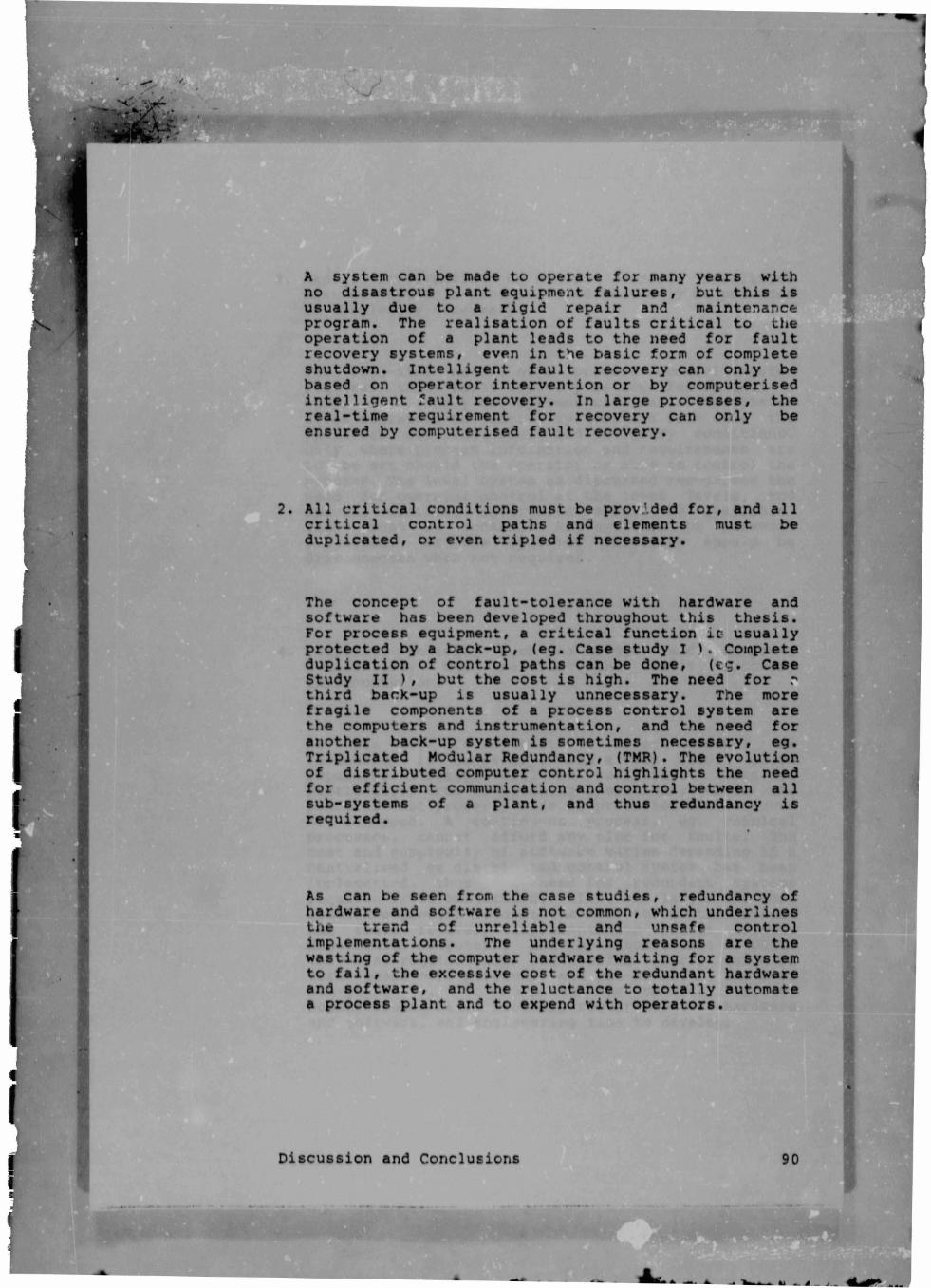
A system can be made to operate for many years with
no disastrous plant equipment failures, but this is
usually due to a rigid repair and maintenance
program. The realisation of faults critical to the
operation of a plant leads to the need for fault
recovery systems, even in the basic form of complete
shutdown. Intelligent fault recovery can only be
based on operator intervention or by computerised
intelligent fault recovery. In large processes, the
real-time requirement for recovery can only be
ensured by computerised fault recovery.
2. All critical conditions must be provided for, and all
critical control paths and elements must be
duplicated, or even tripled if necessary.
The concept of fault-tolerance with hardware and
software has been developed throughout this thesis.
For process equipment, a critical function it- usually
protected by a back-up, (eg. Case study I Complete
duplication of control paths can be done, (eg. Case
Study II ), but the cost is high. The need for r
third back-up is usually unnecessary. The more
fragile components of a process control system are
the computers and instrumentation, and the need for
another back-up system is sometimes necessary, eg.
Triplicated Modular Redundancy, (TMR). The evolution
of distributed computer control highlights the need
for efficient communication and control between all
sub-systems of a plant, and thus redundancy is
required.
As can be seen from the case studies, redundancy of
hardware and software is not common, which underlines
the trend of unreliable and unsafe control
implementations. The underlying reasons are the
wasting of the computer hardware waiting for a system
to fail, the excessive cost of the redundant hardware
and software, and the reluctance to totally automate
a process plant and to expend with operators.
Discussion and Conclusions 90
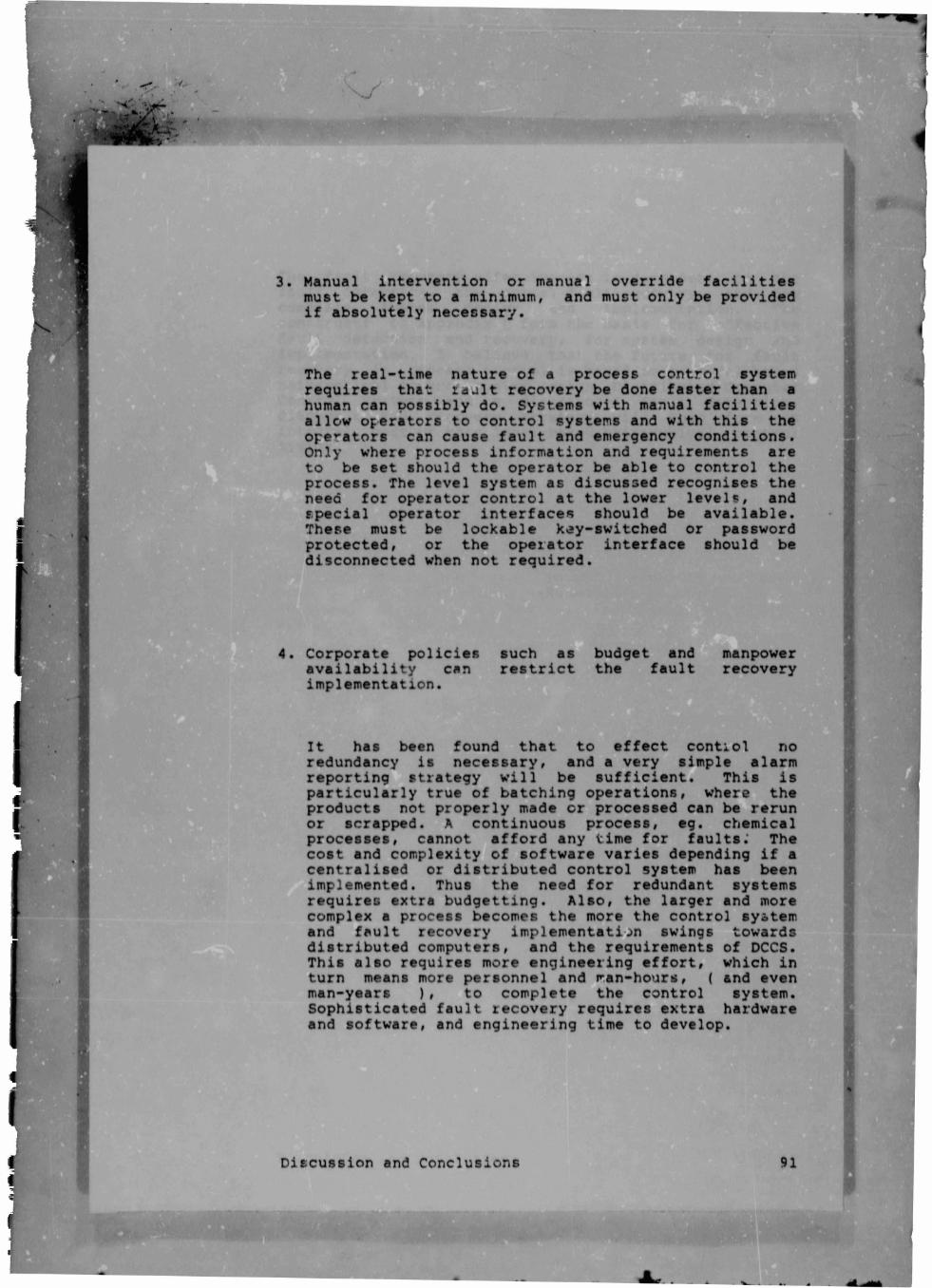
3. Manual intervention or manual override facilities
must be kept to a minimum, and must only be provided
if absolutely necessary.
The real-time nature of a process control system
requires that raalt recovery be done faster than a
human can possibly do. Systems with manual facilities
allow operators to control systems and with this the
operators can cause fault and emergency conditions.
Only where process information and requirements are
to be set should the operator be able to control the
process. The level system as discussed recognises the
need for operator control at the lower levels, and
special operator interfaces should be available.
These must be lockable k^y-switched or password
protected, or the operator interface should be
disconnected when not required.
4. Corporate policies such as budget and manpower
availability can restrict the fault recovery
implementation.
It has been found that to effect control no
redundancy is necessary, and a very simple alarm
reporting strategy will be sufficient. This is
particularly true of batching operations, where the
products not properly made or processed can be rerun
or scrapped. A continuous process, eg. chemical
processes, cannot afford any time for faults.' The
cost and complexity of software varies depending if a
centralised or distributed control system has been
implemented. Thus the need for redundant systems
requires extra budgetting. Also, the larger and more
complex a process becomes the more the control system
and fault recovery implementation swings towards
distributed computers, and the requirements of DCCS.
This also requires more engineering effort, which in
turn means more personnel and ran-hours, ( and even
man-years ), to complete the control system.
Sophisticated fault recovery requires extra hardware
and software, and engineering time to develop.
Discussion and Conclusions 91

Author Horn Timothy Andrew Name of thesis Fault Recovery In Process Control. 1985
PUBLISHER: University of the Witwatersrand, Johannesburg
©2013
LEGAL NOTICES:
Copyright Notice: All materials on the Un i ve r s i t y o f the Wi twa te r s rand , Johannesbu rg L ib ra ry website are protected by South African copyright law and may not be distributed, transmitted, displayed, or otherwise published in any format, without the prior written permission of the copyright owner.
Disclaimer and Terms of Use: Provided that you maintain all copyright and other notices contained therein, you may download material (one machine readable copy and one print copy per page) for your personal and/or educational non-commercial use only.
The University of the Witwatersrand, Johannesburg, is not responsible for any errors or omissions and excludes any and all liability for any errors in or omissions from the information on the Library website.