level
DESCRIPTION
sTRANSCRIPT

Level 1 - LevelRMT Training - 05 /98
1
Fundamental TrainingFundamental TrainingLevel 1

Level 1 - LevelRMT Training - 05 /98
2
Topics: Slide No:• Why measure level? 3 - 5• Level terminology 6 - 19• Technology selection 20 - 29• Rosemount Technology (Pressure 30 - 55
Transmitter, HTG & Hybrid System• Other Technology (Float, Capacitance, 56 - 75
Displacer, Servo, Nucleonic, Laser &
Ultrasound)• Exercise 76 - 80
ContentsContents

Level 1 - LevelRMT Training - 05 /98
3
Why measure level?Why measure level?5 Common Reasons5 Common Reasons
Inventory• keep track of amount of material of material available for a process
Custody Transfer• amount of material that is bought & sold in terms of volume or weight
Effieciency• maximise storage tank capacity• preventing unnecessary expense of purchasing additional vessels
Safety• prevent spillage in open vessels• prevent overpressure conditions in closed vessels that may result in rupture
Consistent Supply• to maintain product quality in a process
» blending, pulp & paper

Level 1 - LevelRMT Training - 05 /98
4
Inventory• Accuracy is primary difference
» better than 3 mm precision needed • Applications need precise measurement because of $$$$$
» Transfer of ownership» Exact quantity must be known» Product cost» Tend to be larger vessels
Process • Applications are more concerned with:
» Control of a product level within a range» Safety (prevent overflow/ pump shutoff)» Monitor inputs of components of a process» Accuracy requirements vary widely
You can have a mixture of process
and inventory applications in a
plant
Why measure level?Why measure level?Inventory vs. ProcessInventory vs. Process

Level 1 - LevelRMT Training - 05 /98
5
Why measure level?Why measure level?Indication vs. ControlIndication vs. Control
Indication
• on-site level check
• operator interpret measurementIndicators
– open loop control system
– help calibrate automatic control system
Control
• closed loop systemprocess point of measure transmitter
controller control valve process

Level 1 - LevelRMT Training - 05 /98
6
I/P LIC
LT
(Inflow)(Inflow)
• Level Loop Issues:– Control At Inflow or Outflow– Non-Self Regulating
Level terminologyLevel terminologyLevel Control LoopLevel Control Loop

Level 1 - LevelRMT Training - 05 /98
7
I/PLIC
LT
(Outflow)(Outflow)
Level terminologyLevel terminologyLevel Control LoopLevel Control Loop

Level 1 - LevelRMT Training - 05 /98
8
Interface
Level
VolumeMassDensity
Level terminologyLevel terminologyParametersParameters

Level 1 - LevelRMT Training - 05 /98
9
Level terminologyLevel terminologyParametersParameters
Liquid A to air/vapor interface
Liquid A
Liquid A to B interface
Liquid B
Interface• Interface measurement finds the boundary
between two liquids stored in the same tank» each liquid has different density

Level 1 - LevelRMT Training - 05 /98
10
Density• Density is a measure of the mass per volume
Example:– grams / cc– pounds / cu ft
• Specific Gravity is a ratio of the density of a fluid to the density of water, thus
density of fluid = SG
density of water
Density of fluid = density of water * SG
Density
Level terminologyLevel terminologyParametersParameters
Mass = Density / Volume
Level 1 - LevelRMT Training - 05 /98
11
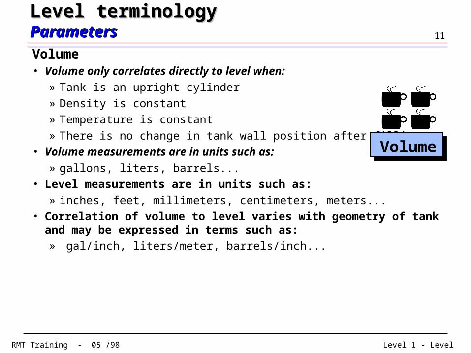
Volume• Volume only correlates directly to level when:
» Tank is an upright cylinder» Density is constant» Temperature is constant» There is no change in tank wall position after filling
• Volume measurements are in units such as:» gallons, liters, barrels...
• Level measurements are in units such as:» inches, feet, millimeters, centimeters, meters...
• Correlation of volume to level varies with geometry of tank and may be expressed in terms such as:» gal/inch, liters/meter, barrels/inch...
Volume
Level terminologyLevel terminologyParametersParameters

Level 1 - LevelRMT Training - 05 /98
12
Level terminologyLevel terminologyParametersParameters
Volume• Vertical Cylindrical Tank
» v = r2l
• Horizontal Cylindrical» v = r2atan[l½/(2r-l)½]+h(l-r)[l(2r-l)]½
• Sphere Tank» v = l2(3r-l)/3
r
h
l
r
hl
r
l

Level 1 - LevelRMT Training - 05 /98
13
Level terminologyLevel terminologyParametersParameters
Volume
• Horizontal Bullet Tank» v = r2/3 * (3r-l) + 2r2(h-2r) *atan[l½/(2r-l)½] + (h-r)[l(2r - l)]½
• Vertical Bullet Tank
» v = r2/3(3r-l) if l r
» v = r2/3(3r-l) if r l (h - r)
» v = r2(h-2r) + [(l+2r-h)2]/3 * [3r-(l+2r-h)]if (h - r) l
h
l
r
h
l
r

Level 1 - LevelRMT Training - 05 /98
14
Level terminologyLevel terminologyParametersParameters
Volume• Tanks with Dished Ends
» no standard shape– use strapping tables to determine volume
10
9
7
5
3
1
Point Level Volume(inches) (gallons)
1 0 02 5 103 10 324 15 685 20 1156 25 1737 30 2308 35 3139 40 39410 100 957
A look-up table that relates level to volume for several discrete points in a tank.
Commonly used to eliminate Bulging Error.
Bulging

Level 1 - LevelRMT Training - 05 /98
15
Density Changes
Steam, vapors, dust
Steam, vapors, dust
0
PSIG-14.7
High vacuum
High vacuum
Viscous or sticky fluids
Viscous or sticky fluids
Temperature extremes
Temperature extremes Agitation Agitation
Abrasive fluids
Abrasive fluids
Corrosive processes
Corrosive processes Foam Foam
...and the technologies may have to handle a number of ...and the technologies may have to handle a number of application conditions.application conditions.
Level terminologyLevel terminologyMeasurement CharacteristicsMeasurement Characteristics

Level 1 - LevelRMT Training - 05 /98
16
Top-down
Bottom-up
Top-Down Measurement• Poses less potential for leakage• devices installed or removed
without emptying tanke.g., dipstick, radar gauge
Bottom-Up Measurement• Typically contacts the process fluid
e.g., pressure transmitter, weigh scale
Bottom-Up vs. Top-Down Measurement
Level terminologyLevel terminologyMeasurement CharacteristicsMeasurement Characteristics

Level 1 - LevelRMT Training - 05 /98
17
• An Inferred measurement is derived from another measurement
Ex: pressure transmitter
HeadPressure = Level , Mass = Level
Density Density
Stability of variables is critical to get a good inferred measurement.
If variables are not stable, compensation needs to be made.
• A Direct measurement looks only at the desired variable
Ex: floats, dipstick
Level terminologyLevel terminologyMeasurement CharacteristicsMeasurement Characteristics
Inferred vs. Direct Measurement

Level 1 - LevelRMT Training - 05 /98
18
Continuous Measurement• Constant detection of
product height
• Concerned with amount of product
• May be used to control addition of other components to the vessel
Point measurement• Has the level reached
this point?
• High or low level detection
• Often used for alarm control
• May start or stop pumps
• May open or close valves
Continuous vs. Point Measurement
Level terminologyLevel terminologyMeasurement CharacteristicsMeasurement Characteristics

Level 1 - LevelRMT Training - 05 /98
19
Non-Contact Non-Contact implies that the device does not touch the fluid, but it could be invasive
Non-intrusiveNon-intrusive implies that the device may come in contact with the fluid, but does not protrude into the fluid or interfere with fluid movement
Intrusive
Non-invasive Non-invasive implies that the device does not pass the walls of the tank nor touch the process directly
Non-Contact vs. Non-Invasive vs. Non-Intrusive
Level terminologyLevel terminologyMeasurement CharacteristicsMeasurement Characteristics

Level 1 - LevelRMT Training - 05 /98
20
Hydrostatic
RadarTuning ForkFloat
Capacitance
Dipstick
Sight glass
Gage Glass
Weight
Differential Pressure
Ultrasonic Gap
Displacer
Nuclear
Ultrasonic
Bubbler
Technology selectionTechnology selectionLevel Measurement TechnologiesLevel Measurement Technologies

Level 1 - LevelRMT Training - 05 /98
21
Contacting Noncontacting Point Continuous Liquids Solids
BubblersCapacitanceConductivityDisplacersFloatsHTGHydrostaticLaserMagnetostrictiveNucleonicOpticalPhase DifferenceRadarResistance TapeRotation SuppressionServoTape LevelThermalUltrasonicVibrationWeighing
Technology selectionTechnology selectionClassification of Level Measurement TechnologiesClassification of Level Measurement Technologies

Level 1 - LevelRMT Training - 05 /98
22
Note: Only continuous devices included
Technology selectionTechnology selectionClassification of Level Measurement TechnologiesClassification of Level Measurement Technologies

Level 1 - LevelRMT Training - 05 /98
23
• Why is the level measurement needed?What are you try to measure?What are you trying to achieve?
– Indication of fluid level– Alarm set point to prevent spill over– Transfer (Sale) of product– Contol of Product Mix– Leak Detection– Interface detection
• What are the conditions within or on the vessel? Product turbulence Obstructions Mounting constraints Angle of repose for solids Temperature and pressure limits
Technology selectionTechnology selectionFactors To Consider Factors To Consider

Level 1 - LevelRMT Training - 05 /98
24
Technology selectionTechnology selectionFactors To Consider Factors To Consider
• What are the environmental conditions? Ambient Temperature Humidity Vibration Electro Magnetic Interference(EMI) Transient protection
• What are the product characteristics? Corrosive Viscous Dusty, Foam Variable Density Variable Dielectric constant Tendency to Coat Interfaces, gradients, suspended solids Steam or other vapors

Level 1 - LevelRMT Training - 05 /98
25
Common Density/ Temperature Changes
Technology selectionTechnology selectionFactors To Consider Factors To Consider

Level 1 - LevelRMT Training - 05 /98
26
Typical Dielectric/ Temperature Changes
Technology selectionTechnology selectionFactors To Consider Factors To Consider

Level 1 - LevelRMT Training - 05 /98
27
Technology selectionTechnology selectionFactors To Consider Factors To Consider
• What are the instrument requirements? Performance requirements Location approvals Power requirements Output requirements Number, location, and size of taps Total costs
– Product – Installation – Maintenance

Level 1 - LevelRMT Training - 05 /98
28
Environmental Factors
ProcessConditionsDevice
Technology selectionTechnology selectionPerformance Consideration Performance Consideration
Direct vs inferredMeasurement capabilitiesRangeability
Temp changesVibrationNoise
Density changestemperature changesstatic pressureagitationaerationfoamdielectric changes

Level 1 - LevelRMT Training - 05 /98
29
Approximate values are shown. Pressure and temperature limits are shown independently of each other.Temperature, oF
-240 32 195 600 800-40-100 320 400 900+
Pre
ssu
re, P
SI
atm
10000+
73
1000
3626
Displacer
Nucleonic
Ultrasonic
Ultrasonic Point
Pressure/HTG
Radar
Capacitance
Pressure w/ seals
Technology selectionTechnology selectionWorking Capabilities Vary with TechnologiesWorking Capabilities Vary with Technologies

Level 1 - LevelRMT Training - 05 /98
30
In open vessel a pressure transmitter mounted near the bottom of the tank will measure the pressure corresponding to the height of the fluid above it.
Open Vessel Level Measurement
XMTR
HL
Patm
Phead
Patm
What happen to Atmospheric pressure? Cancelled
Off
Phigh - Plow = Phead
Plow = Patm
Phigh = Phead + Patm
Rosemount technologiesRosemount technologiesPressure Transmitters Pressure Transmitters

Level 1 - LevelRMT Training - 05 /98
31
What happens when the liquid level drop below the sensor ?
Transmitter mounted above the tap in an open vessel
XMTR
HL0%
100%
0% h
g
The 0% has to be at least at the same level as the transmitter sensor or below the tapping point..
The sensor will not be able to sense any pressure change !!
Rosemount technologiesRosemount technologiesPressure Transmitters Pressure Transmitters

Level 1 - LevelRMT Training - 05 /98
32
“Zero Suppression” is often applied to compress the range of the transmitter OR to cancel the effects of the liquid head in the pipe connecting the transmitter to a tank when the transmitter is mounted below the vessel connection.
XMTR
HL
Actual ZeroSuppressed
4mA
20mA Max. Level
Min. Level Ra
ng
e
XMTR
HL
Actual Zero Suppressed
4mA
20mA Max. Level
Min. Level
Ra
ng
e
At min. level the High side pressure is high than the low side pressure
Rosemount technologiesRosemount technologiesPressure Transmitters Pressure Transmitters

Level 1 - LevelRMT Training - 05 /98
33
“Zero Elevation” is often applied to cancel the effects of the head caused by the seal fluid in the reference leg (low side) of a transmitter measuring level in a pressurized vessel.
XMTR
Actual Zero Elevated
4mA
20mA Max. Level
Min. Level Ra
ng
e
L H At min. level the low side pressure is high than the high side pressure
Rosemount technologiesRosemount technologiesPressure Transmitters Pressure Transmitters

Level 1 - LevelRMT Training - 05 /98
34
Dry leg: no fluid in low side impulse piping, or leg
If the gas above the fluid does not condense, the piping for the low side of the transmitter will remain empty.
Closed Tank Level Measurement (Dry Leg)
XMTR
HL
Phigh = Ptop+Phead
Plow = Ptop
Ullage or Vapor
Phead
Phigh - Plow = Phead
Rosemount technologiesRosemount technologiesPressure Transmitters Pressure Transmitters

Level 1 - LevelRMT Training - 05 /98
35
Wet leg pressure is additive to pressure on low side of the transmitter.
If the gas above the liquid condenses, the piping for the low side of transmitter will slowly fill with liquid. To eliminate this potential error, the pipe is filled with a convenient reference liquid.
Closed Tank Level Measurement (Wet Leg)
XMTRHL
Phead
Ptop= Ullage
Phigh =Phead+Ptop
Phigh - Plow = Phead - Pwet leg
Pwet
Plow=Pwet leg+Ptop
Rosemount technologiesRosemount technologiesPressure Transmitters Pressure Transmitters
Level 1 - LevelRMT Training - 05 /98
36
• Bottom-mount technology: potential leakage• Often requires 2 taps• Variable density creates errors• Temperatures beyond 600 F• High vacuum applications are tricky• Highly corrosive processes limit life• Abrasive processes can damage diaphragms• Liquids Only
Limitations
Rosemount technologiesRosemount technologiesPressure Transmitters Pressure Transmitters

Level 1 - LevelRMT Training - 05 /98
37
Consists of air supply, pressure regulator, flow meter, transmitter & extended tube.
Can be used for very corrosive applications.
Tank vented.
Air is bubbled through the tube at a constant flow rate. The pressure required to maintain flow is determined by the vertical height of the liquid above the tube opening times the specific gravity.
Pin(flow=const)
Bubbler System
Pressure to maintain flow = Phead
S.Gf
H
Phead = H * S.Gf
TXR
Rosemount technologiesRosemount technologiesPressure Transmitters Pressure Transmitters

Level 1 - LevelRMT Training - 05 /98
38
Gauge Pressure Transmitter
Air Supply
Valve• Allows dp to be a top
down measurement• No process contact with
transmitter• Open or low pressure • Control of Air supply is
important for accuracy
Application of Bubbler system:
Rosemount technologiesRosemount technologiesPressure Transmitters Pressure Transmitters

Level 1 - LevelRMT Training - 05 /98
39
Reliable, Simple, Easy to Use, Well Understood, Flexible Uses:
Differential PressureTransmitter
Diaphragm Seals extend limitations due to process conditions such as:
high temperatures
corrosion
viscous materials
suspended solids
plugging
sanitary needs
Rosemount technologiesRosemount technologiesPressure Transmitters Pressure Transmitters
Remote Seals

Level 1 - LevelRMT Training - 05 /98
40
•CPI / HPIBatch reactors digestersfractionatorsdistillation column bottoms and reflux drumsseparators surge drums reservoirs intermediate storage...
•Powerdrum level dearators...
•Pulp & PaperHeadboxStock TanksChemical Storage tanksEvaporatorsLow concentration liquor tanks...
•Food and BeverageFermentorsstorage tanksaging tanks brew kettles...
And many more!
Typical Pressure Applications
Rosemount technologiesRosemount technologiesPressure Transmitters Pressure Transmitters

Level 1 - LevelRMT Training - 05 /98
41
It is basically a method for measuring mass.
A local processor handles all the real-time calculations for transmitter algorithms and equations for MASS, DENSITY, LEVEL and VOLUME.
Top transmitter PT only used on non-atmospheric tanks to compensate for ullage pressure differences.
Middle transmitter PM located at a specific distance “H” above PB to calculate liquid density (PB-PM)
Bottom transmitter PB located at the base of the tank measures static head.
RTD measures tank contents temperature for reference correlations.
Rosemount technologiesRosemount technologiesHydrostatic Tank Gauging (HTG) Hydrostatic Tank Gauging (HTG)

Level 1 - LevelRMT Training - 05 /98
42
Rosemount technologiesRosemount technologiesHydrostatic Tank Gauging (HTG) Hydrostatic Tank Gauging (HTG)
H
HBT
PB
PM
PT
Volume =
Level =
Mass =
Density =
(PB - PT) x Area
(PB - PM ) / H
Mass / Density
(PB - PT) /Density + HBT
A system approach to tank inventory
TT
Effective Level Measurement Options:

Level 1 - LevelRMT Training - 05 /98
43
Top Pressure Transmitter
Middle Pressure Transmitter
Temperature Sensor
Bottom Pressure Transmitter
(1 unit per tank)
All Smart transmitters are in multi-drop mode - All Smart transmitters are in multi-drop mode - Digital signalsDigital signals only only
(can take up to 14 SAMs)
(can take up to 31 AIMs)
[Handles tank calculaton]
(obtain data from SAM & convert to std MODBUS outputs)
Smart Application Module (SAM)
HARTCommunicator
Application Interface Module (AIM)
SCADA SCADA PackagePackageRS-485 MODBUS
Communications Network
Rosemount technologiesRosemount technologiesHydrostatic Tank Gauging (HTG) Hydrostatic Tank Gauging (HTG)

Level 1 - LevelRMT Training - 05 /98
44
Multi-Parameter MeasurementsMASS: Inventory and BillingDENSITY: Quality ControlVOLUME: Inventory & BillingLEVEL: Tank Capacity
Continuous Density Measurement Improved Accuracy High Reliability Low Maintenance Diagnostic Easy Installation Non-Intrusive No Moving Parts
Advantages of HTG
Rosemount technologiesRosemount technologiesHydrostatic Tank Gauging (HTG) Hydrostatic Tank Gauging (HTG)

Level 1 - LevelRMT Training - 05 /98
45
Top Pressure Transmitter
Middle Pressure Transmitter
Temperature Sensor
Bottom Pressure Transmitter
(1 unit per tank) (can take up to 14 SAMs)
(can take up to 31 AIMs)
[Handles tank calculaton]
(obtain data from SAM & convert to std MODBUS outputs)
Smart Application Module (SAM)
HARTCommunicator
Application Interface Module (AIM)
SCADA SCADA PackagePackageRS-485 MODBUS
Communications Network
When the Middle transmitter is removed & the Top Pressure When the Middle transmitter is removed & the Top Pressure Transmitter is replaced by a Radar Gauge, then the whole system Transmitter is replaced by a Radar Gauge, then the whole system will be known as will be known as Hybrid Inventory SystemHybrid Inventory System
Rosemount technologiesRosemount technologiesHybrid Inventory System Hybrid Inventory System
Radar Gauge

Level 1 - LevelRMT Training - 05 /98
46
Rosemount technologiesRosemount technologiesHybrid Inventory System Hybrid Inventory System
Top Pressure Transmitter
Middle Pressure Transmitter
Temperature Sensor
Bottom Pressure Transmitter
Radar Gauge
H
L
D
• LEVEL is calculated by Radar Gauge L = H - D
• VOLUME is computed by Radar Gauge Through Strapping Table
– relationship level to volume• DENSITY is computed by the system
S.G = Head Pressure / Level– Head pressure measured by
bottom pressure transmitter• MASS is computed by the system
Mass = Density X Volume• CORRECTING for Density & Volume
back to standard values is computed
Measurement Options:

Level 1 - LevelRMT Training - 05 /98
47
Advantages of Hybrid System
Rosemount technologiesRosemount technologiesHybrid Inventory Systems Hybrid Inventory Systems
Highly accurate Multi-Parameter Measurements MASS: Inventory and Billing DENSITY: Quality Control VOLUME: Inventory & Billing LEVEL: Tank Capacity
Radar can be installed without removing the tank from service
Radar unit can be used with or without a stilling well Process conditions up to 375°F (190°C) and 150 psi (10 bar) Optional average temperature measurement Good for density-stratified products

Level 1 - LevelRMT Training - 05 /98
48
Wavelength, Meters
10 -11
10 7
10 5
10 3
10 1
10 -5
10 -3
10 -1
10 -9
10 -7
10 -13
10 2
10 18
10 16
10 14
10 12
10 10
10 8
10 6
10 4
10 20
10 22
Frequency Cycles/second
gamma rays
x-rays
ultra violet
visible light
------ultra high freq----------
----------TV broadcasting------------------FM Radio-------------
-------low frequency------------
Radar,
3-30 GHz
Microwave oven,
2 - 10 GHz
Cellular, pager,
300-3000 MHz
Electromagnetic Spectrum Radar is an
Electromagnetic Wave
Radio Detection And Ranging
--------super high freq---------
Rosemount technologiesRosemount technologiesRadar Gauge Radar Gauge

Level 1 - LevelRMT Training - 05 /98
49
• Pulse » Measures range ( distance )» Transmits a pulse and measure time until
echo is received» Accuracy depends on ability to measure time
– Radar signals travel at the speed of light.– Must measure in picoseconds ( x10-12 ) !– Cost-effective electronics do not exist to do this
accurately !
Radar Techniques
Rosemount technologiesRosemount technologiesRadar Gauge Radar Gauge

Level 1 - LevelRMT Training - 05 /98
50
• FMCW: Frequency Modulated Continuous Wave
» Does NOT calculate time-of-flight
» Evaluates the phase difference between the transmitted and return signal
» Plotting these phase differences against the transmitted signal yields a result proportional to distance
Radar Techniques
Rosemount technologiesRosemount technologiesRadar Gauge Radar Gauge

Level 1 - LevelRMT Training - 05 /98
51
• Non Contact, Non Intrusive
• Tolerates Wide Range of Process Conditions
» Corrosive Processes
» High Temperatures
» Changes in Vapor Space
» Variable Density
» Variable Dielectric
» Viscous or Sticky Products
• Low Maintenance
• No Special Licenses Required
• Can measure long distances
• Liquids, pastes, solids
Rosemount technologiesRosemount technologiesRadar Gauge Radar Gauge
Advantages of Radar Gauge

Level 1 - LevelRMT Training - 05 /98
52
• Sensors can be completely removed from process by use of a window made out of a nonmetallic material, such as Teflon, Ryton, Ceramic
• Sensors can be removed from the process without opening the vessel
Radar Application Considerations
• Cost• May not work with processes with low dielectric constant• May not work in applications with large amounts of
turbulence• Process connections tend to be large (>4” flanges)
Radar Limitations
Rosemount technologiesRosemount technologiesRadar Gauge Radar Gauge

Level 1 - LevelRMT Training - 05 /98
53
•Pulp & Paper
»High Density Storage
»Color tanks
»Bleach tanks
»Hydropulpers
»Retention tanks
»Black liquor tanks
•Pharmaceutical
»Batch reactor
»Chemical storage
•Power
»Slurries
•Chemical»Polymers»Latex»High temp»LPG tanks»Butane sphere»Batch reactors»Two-phase sludge»Cyclohexane
•Minerals»Steel Scale Holding Tanks
And More!
Possible Applications
Rosemount technologiesRosemount technologiesRadar GaugeRadar Gauge

Level 1 - LevelRMT Training - 05 /98
54
Both technologies
Top down, non contact
Easy to install
Good for abrasive materials, slurries
Not affected by changing fluid properties: density, conductivity, dielectric
Radar vs. Ultrasonic Gauge
Differences:Radar
Full vacuum to several hundred psi
Wide temperature limits
Can handle steam, fog, vapors
Can handle some foams and agitation
Can be used with windows
UltrasonicVery slight vacuum to about 100 psiNarrow temp band (<200 F)Is greatly affected by changes in vapor spaceSignal is lost in foam and agitation
Rosemount technologiesRosemount technologiesRadar GaugeRadar Gauge
Similarities:

Level 1 - LevelRMT Training - 05 /98
55
Gas Temp (oC) RADAR ULTRASOUNDmillion m/s m/s
Dry Air 0 299.91 331.8100 299.94 386
Water vapor 100 299.10 404.8
Carbon Dioxide 0 299.85 250.050 299.87 279.0
Ammonia 0 299.93 415.0
Acetone 0 297.64 223.0
Source: Instrument Engineer’s Handbook, Liptak
Radar vs. Ultrasonic Gauge
Rosemount technologiesRosemount technologiesRadar GaugeRadar Gauge

Level 1 - LevelRMT Training - 05 /98
56
Tank
Isola
tin
g
Valv
e
Float
Drain Valves
Indicator
IndicatorExternal Still pipe to guide the float
Float
Internal Still pipe to guide the float
Float-operated gauge level-indicator, indicates liquid level in cone or flat roof unpressurised tanks.Recommended for use on tanks storing water, fuel, oil, chemicals or other liquid products where operations do not require extreme accuracy.
Other technologiesOther technologiesFloat MechanismFloat Mechanism

Level 1 - LevelRMT Training - 05 /98
57
C = KEoAd
where K = dielectric constant of materialEo = permitivity of vacuum
A = Area of plates (probe)C = capacitance (pF)d = distance between plates
d
k
• A capacitance instrument measures amount of capacitance between two plates of a capacitor.
• The capacitance of a capacitor increases if a dielectric is placed between the plates
• Circuit applies high frequency signal to probe
Other technologiesOther technologiesCapacitance ProbeCapacitance Probe

Level 1 - LevelRMT Training - 05 /98
58
Nonconductive Fluid
d
Conductive Fluid
NonconductiveCoating
• Process fluid is the dielectric barrier
• Tank Wall forms second plate
• The variation of dielectric is the measurement
• Process fluid is the second plate
• Insulation on probe is dielectric
• The variation of the plate size is the measurement
How Capacitance varies with process fluid?
Level is proportional to dielectric change
Level is proportional to plate area change
Other technologiesOther technologiesCapacitance ProbeCapacitance Probe

Level 1 - LevelRMT Training - 05 /98
59
• Limitation– Change in Dielectric creates error– Coating on probe by product creates errors– With non metallic tanks or tanks without vertical
walls, addition of reference probe is required– Calibration can be difficult especially since one
cannot “bench calibrate”– Changing vapor space can affect output
Other technologiesOther technologiesCapacitance ProbeCapacitance Probe

Level 1 - LevelRMT Training - 05 /98
60
•Pulp & PaperSewage levelLiquor tanksBulk solids
•ChemicalInterface: fatty acid/water, oil/waterCarbon blackSeparators
•Food & BeverageStorage silos
•Oil & GasWater bottomWater cut
Potential Applications
Other technologiesOther technologiesCapacitance ProbeCapacitance Probe

Level 1 - LevelRMT Training - 05 /98
61
Angular movement is then converted to electrical or pneumatic output.
pounds
0
pounds
0Based on Buoyance Force
The displacer is buoyed up by a force proportional to the weight of the liquid it displaces
Vertical movement of the displacer is converted to angular movement by mechanical linkages
Buoyant force increases as level rise
Other technologiesOther technologiesDisplacersDisplacers

Level 1 - LevelRMT Training - 05 /98
62
Liquid Level
Measurement
Interface
Measurement
Density
Measurement
Good for short span measurement
Other technologiesOther technologiesDisplacersDisplacers

Level 1 - LevelRMT Training - 05 /98
63
Benefits:• Simple, Reliable.• Good for Interface measurements.• Good for Density measurements.• Unaffected by Agitation.• Tolerates High Temperatures and pressures.• Point or Continuous .
Limitations:– Does not tolerate viscous, dirty, or sticky fluids– Variable density causes errors in level measurement– Typically used for smaller spans (cost effective)– Must be installed carefully– Intrusive & Contact
Other technologiesOther technologiesDisplacersDisplacers

Level 1 - LevelRMT Training - 05 /98
64
• Typical Applications:Oil and Water interfaceOil and Gas SeparatorsStripper Reflux Drum LevelDehydration UnitsEffluent SeparatorsAbsorption TowersCondensate Discharge AccumulatorsDensity and Interface Measurements
Other technologiesOther technologiesDisplacersDisplacers

Level 1 - LevelRMT Training - 05 /98
65
Uses a combination of a displacer and a spring balance
The servo motor strives to obtain an equilibrium between the displacer and the balance. Any change in level will cause a change in equilibrium.Advantages:
– Very precise (1 mm accuracy)– Can measure level, interface– relatively low cost
Limitations:– Intrusive– Mechanical linkages
Cable
Storage Drum
Balance Detector
Servo
Motor
Displacer
Other technologiesOther technologiesServo GaugingServo Gauging

Level 1 - LevelRMT Training - 05 /98
66
Gamma rays are emitted from the source. The presence or absence of the gamma rays is measured by the detector.
Nucleonic level switches use radioisotope sources sized to provide measurable radiation at the detector when no product material is present between source and detector.
DetectorGamma
Source
Single Point System
Other technologiesOther technologiesNucleonic GaugingNucleonic Gauging

Level 1 - LevelRMT Training - 05 /98
67
Nucleonic level transmitters use the same radioisotope sources, but respond to the total absorption of gamma rays as they pass from the source to detector.
The amount of radiation reaching the detector is inversely proportional to the amount of material in the vessel.
Detector
Source
Continuous System
Other technologiesOther technologiesNucleonic GaugingNucleonic Gauging

Level 1 - LevelRMT Training - 05 /98
68
– Unaffected by:• High temperatures• High Pressures• Corrosive Materials• Abrasive Materials• Viscous Materials• Agitation• Clogging/Plugging
– Point and Continuous
– Liquids and Solids
– Interface (based on H2 density)
Advantages:
– Large density changes can create errors
– Layer of coating on vessel walls create errors
– Licensing Required– Leak Checks required– Cost
Limitations:
Other technologiesOther technologiesNucleonic GaugingNucleonic Gauging

Level 1 - LevelRMT Training - 05 /98
69
•ChemicalDistillation TowerBatch ReactorStorage TanksResin Bed levelHydrocracker reactor
•Pulp & PaperDigester LevelWood Chip BinsBleach TowerConsistencyEffluent WasteSlurriesLiquor concentrates
•RefiningFractionator TowerSurge TanksCoke Drum InterfaceDesalter
•Food and BeverageHopper LevelBlending Vats
•Mining Crusher LevelStorage silosSlurries
•UtilitiesSO2 / Lime scrubber
Fly ash Slurries
Other technologiesOther technologiesNucleonic GaugingNucleonic Gauging
Typical Applications

Level 1 - LevelRMT Training - 05 /98
70
glass windowlaser device
• Function: Uses infrared light to send a focused beam towards surface. Time of travel and reflection is measured.
• Narrow, focused beam: good for applications with space restrictions.
• Non contacting: uses a window• Accuracy: +/- 1 cm• Works best in cloudy, shiny liquids or
solids• May pass through surfaces of clear, still
fluids• Cannot tolerate dust, fog, steam or vapors• High cost• Alignment is critical
Other technologiesOther technologiesLaserLaser

Level 1 - LevelRMT Training - 05 /98
71
• Advantages:Non ContactNo element contaminationCan be used for liquids and solidsTolerates Many Process
Conditions:
Sound Waves
A sound pulse(9 to 160 kHz) is transmitted and reflects off the surface back to the transceiver. The true reflected echo pulse is extracted and the time interval between transmission and reception is evaluated electronically.
The higher the level the faster echo reflected
Varying Density Corrosive Processes Viscous Product Varying Dielectric Sludge Buildup
Other technologiesOther technologiesUltrasonic GaugingUltrasonic Gauging

Level 1 - LevelRMT Training - 05 /98
72
• Conditions of the vapor space impact speed of signal travel and thus, the measurement
• Changes could be due to:– temperature– dust– vapor composition– stratification of the vapor
• Some units have temperature compensation
• Gas blankets can be used to provide uniform vapor space condition
Sound Waves
Application Considerations
Other technologiesOther technologiesUltrasonic GaugingUltrasonic Gauging

Level 1 - LevelRMT Training - 05 /98
73
• Process surface conditions can affect signal return . Surface must have ability to reflect signal.
• Heavy agitation and foam may cause signal to be absorbed
• Vortex in fluid can misdirect signal• In open, outdoor installations, wind
can blow signal off coarse• Stilling wells can be used to isolate
the surface and contain signal.
Application Considerations
Other technologiesOther technologiesUltrasonic GaugingUltrasonic Gauging

Level 1 - LevelRMT Training - 05 /98
74
Limitations– not suitable for vacuum service– Cannot tolerate high temperatures (>200 F)– Foam interferes with signal– Agitation may distort signal– Internal obstacles can create false echoes– Nearby equipment could generate frequencies that
will cause errors– Vapor pressure limited to 50 psi
Other technologiesOther technologiesUltrasonic GaugingUltrasonic Gauging

Level 1 - LevelRMT Training - 05 /98
75
•ChemicalDistillation chamberCorrosivesSlurriesLatex PVCWaxes
•Food and BeverageDearating vesselalcohol fermenterbaking batterchocolatedairy productsgrain storage
•Cryogenic systems (point level)
•Waste waterClarifierSettling tanksReservoirsFlood controlSludge levels
•Pulp & PaperBlack liquor w/ solids
•PharmaceuticalEmulsionsLotions
•MarineFuel or ballast water indicationBilge alarm
Other technologiesOther technologiesUltrasonic GaugingUltrasonic Gauging
Typical Applications

Level 1 - LevelRMT Training - 05 /98
76
1. Which has the best accuracy on 6 meter High Water tank?A. Hollow or glass fill float with mechanical gauge (1 inch)B. “Servo” Gauge (1 mm)C. Pressure Transmitter ±0.1% of F.S [ ]
2. An inground reservoir is 5 meters deep. Which of the following method(s) will be suitable to measure and transmit the level without having to dig a hole to reach the bottom of the reservoir or the scour main. (Answer Yes [Y] or No [N])
A. Differential Pressure [ ]B. Servo Level Gauge [ ]C. Capacitive Probe [ ]D. Nucleonic Gauging [ ]E. Ultrasonic Gauging [ ]F. Radar Gauging [ ]G. Bubbler System [ ]
ExerciseExercise

Level 1 - LevelRMT Training - 05 /98
77ExerciseExercise
3. For HTG, why is a 2nd Pressure Transmitter added to tank in the middle ?
4. Which one of the following tank gauging system is based on Mass?(A) Radar(B) Nucleonic(C) Servo Balance(D) HTG [ ]
5. Which of the following statement about Radar Gauge is NOT True ?(A) Top-down mounting(B) Can handle agitated & sticky process fluid(C) Can be used on a tank with non-metallic internal surface.(D) Can handle process with deep vacuum [ ]

Level 1 - LevelRMT Training - 05 /98
78
10’
5’Assuming SG is = 1.1
What is the volume?____________ft3
What is the density of this fluid?___________#/ft3
What is the mass?__________pounds
What is the pressure level reading? ________in H2O
water = 62.4 # / ft3
ExerciseExercise
6.
Level 1 - LevelRMT Training - 05 /98
79
10’
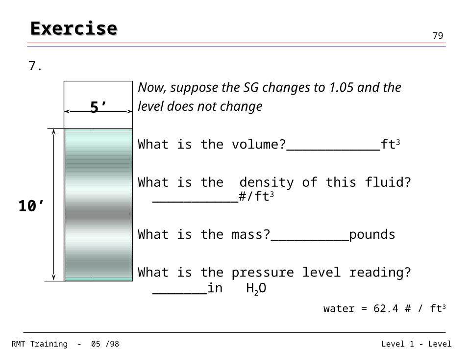
5’Now, suppose the SG changes to 1.05 and the
level does not change
What is the volume?____________ft3
What is the density of this fluid?___________#/ft3
What is the mass?__________pounds
What is the pressure level reading? _______in H2O
water = 62.4 # / ft3
ExerciseExercise
7.

Level 1 - LevelRMT Training - 05 /98
80ExerciseExercise
Pmeasured = 150 inH2O
s.g. = 1.5
Pin(flow=const)
What is the fluid level in the tank?
8.