“Let’s Make a Difference” - nctx-tpwa.org · o. Slope Stabilization . oAlbert Atterberg, Henry Darcy, Joseph Boussinesq, William Rankine, Karl Terzaghi oAtterberg Limits Test,
27
“Let’s Make a Difference” Presented by: Samuel Tran, P.E. October 22, 2015
GEOTECHNICAL ENGINEERING o Surface and Subsurface Construction
o Tunneling, Structural Foundation, Earthwork
o Soil Mechanics o Plasticity Index, Moisture, Consolidation, Swell Potential
o Ground Improvement o Lime / Cement Stabilization o Vibro Compaction o Band Drains
Presenter
Presentation Notes
Tunneling – analyze rock consistency, observe water table Structural Foundation – residential homes, commercial buildings, roadways Earthwork – embankments, excavation, filling Soil Mechanics – Soil Properties – moisture content, unit weight, void ratio, shear strength, compressive strength -analyze data to provide recommendations Ground Improvements – -Lime/Cement – Stiffen subgrade (Not recommended in high sulfate concentrated soil) -Vibro Compaction – stabilize by compacting granular soil up to 100 ft -Band Drains – vertical drains install in clay to accelerate consolidation
o Slope Stabilization
o Albert Atterberg, Henry Darcy, Joseph Boussinesq,
William Rankine, Karl Terzaghi o Atterberg Limits Test, Permeability, Stress Distribution,
Earth Pressure, Bearing Capacity for foundations
GEOTECHNICAL ENGINEERING
Presenter
Presentation Notes
Slope Stability –Identify critical slip surface (lowest factor of safety) - extend soil nail, piers, beyond failure plane - model how to improve slope to 1.5 factor of safety http://zhh.slope.com.cn/wp-content/uploads/2012/04/Slope-stability-analysis.jpg
o Shallow Foundation o Spread Footing o Slab-On-Grade o Mat Foundation
FOUNDATION RECOMMENDATIONS
Presenter
Presentation Notes
Slab on grade & Mat Foundation are similar. Mat thickness is uniform and typically design for large loads. Slab & Beam –monolithic slab http://www.everything-about-concrete.com/images/IMG00146-20100528-0719.jpg http://studio-tm.com/constructionblog/wp-content/uploads/2010/11/spread-footings-framing-03.jpg
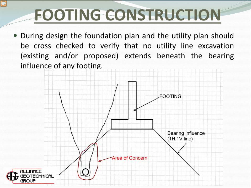
FOOTING CONSTRUCTION During design the foundation plan and the utility plan should
be cross checked to verify that no utility line excavation (existing and/or proposed) extends beneath the bearing influence of any footing.
Presenter
Presentation Notes
If over-excavation and moisture conditioning and/or replacement with low PI select fill is required beneath the footings, the excavation limits beyond the footings both horizontally and vertically should be verified. After excavation for the footings, Look for soft spots Perform probing of the subgrade Verify that the foundation area is level or suitably benched.
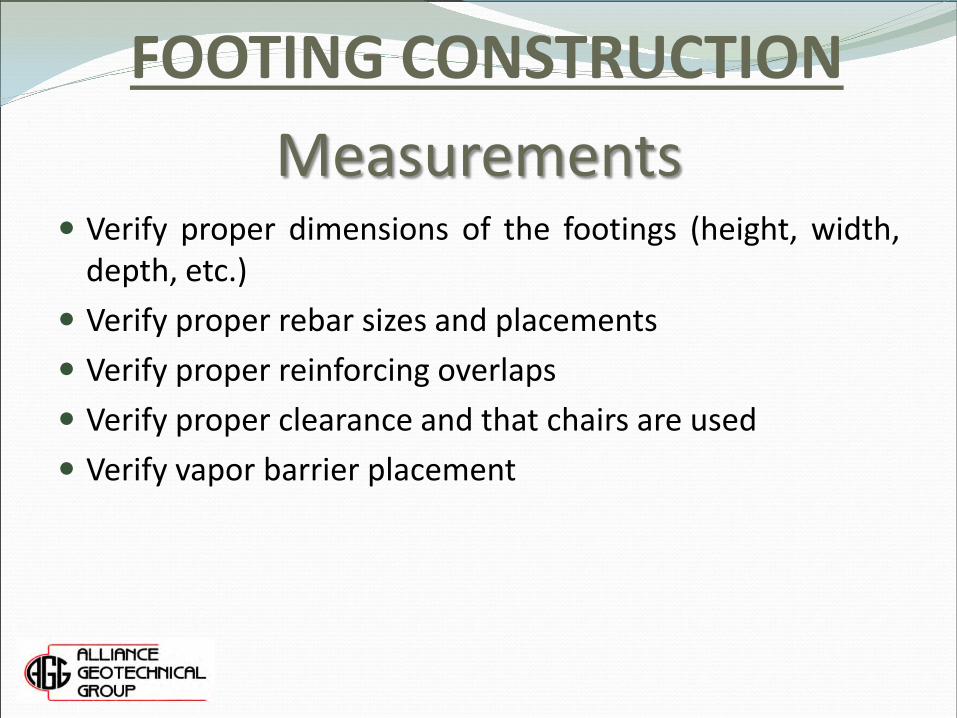
Measurements Verify proper dimensions of the footings (height, width,
depth, etc.) Verify proper rebar sizes and placements Verify proper reinforcing overlaps Verify proper clearance and that chairs are used Verify vapor barrier placement
FOOTING CONSTRUCTION
Prior to Concrete Placement
Verify that the base is free of loose soil and debris
Verify that there is no ponding water Verify that the subgrade has not softened due to being
saturated by rain
FOOTING CONSTRUCTION
Presenter
Presentation Notes
-Proofroll subgrade and Suggest to put in line item in construction budget for soil replacement if soft area is encountered
o Deep Foundation o Straight Shaft Piers o Structural Floor over crawl space or void space o Pier Foundation with slab-on-grade
o Piles o Micropiles, Sheet Piles, Soldier Piles o Timber, Steel, Composite Piles Prestressed Concrete Piles,
FOUNDATION RECOMMENDATIONS
Presenter
Presentation Notes
Prestressed Concrete Piles (18”-24” diameter) – Concrete with rebar/tendons Composite Pile – H steel beams with concrete http://www.ormiston.co.nz/images/gallery/Pile%20Driving.JPG
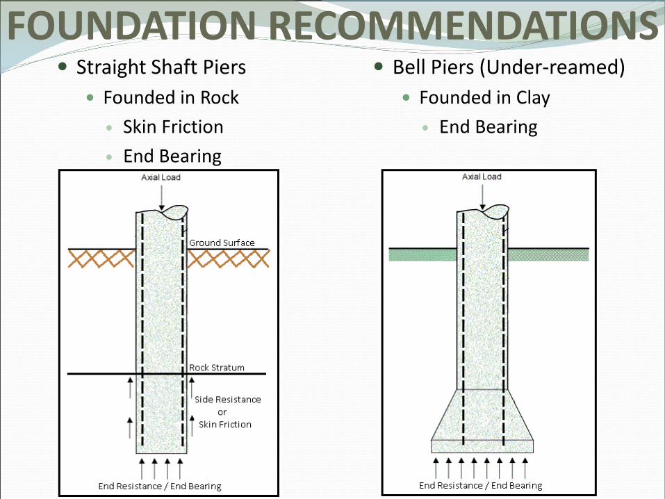
FOUNDATION RECOMMENDATIONS Straight Shaft Piers
Founded in Rock Skin Friction End Bearing
Bell Piers (Under-reamed) Founded in Clay
End Bearing
Engineering staff reviews the approved structural drawings and geotechnical report Verify Foundation Type, Penetration, Bearing Stratum Identify the pier types and locations
Pre-meeting with the Geotechnical Engineer, Driller, &
Engineering Technician
PIER DRILLING INSPECTION
Presenter
Presentation Notes
-Make sure structural drawings match with geotechnical report -Make sure everyone is on the same page: GC, engineers, subcontractor, client
PIER DRILLING INSPECTION
Presenter
Presentation Notes
-Pier plans are marked with Pier ID and date drilled
Engineering Technician Verify Technician has updated structural plans Verify Diameter and Penetration
Drilling Contractor Required to have a straddle bar, plumb bob and pier tape Follow direction of the engineering technician
PIER DRILLING INSPECTION
PIER DRILLING INSPECTION
Presenter
Presentation Notes
Using the straddle Bar Photo taken by AGG
PIER DRILLING INSPECTION
Presenter
Presentation Notes
Verify the auger bit is the correct size for the pier hole Verify the soil material as the drilling proceeds Make sure the ground surface around the pier hole is clean The technician will verify the bearing stratum once it is encountered and direct the driller to clean out the hole. Verify the hole is clean and then measure the depth to the bearing stratum Verify the bearing material is the same as the penetration proceeds Verify the pier hole is clean prior to measuring the depth of the pier hole to determine the total penetration Photo taken by AGG
PIER DRILLING INSPECTION Excessive water seepage or cave in will require steel casing The casing diameter and length needs to be recorded
Each Steel Casing should be properly identified
Presenter
Presentation Notes
Casing inner diameter MUST BE GREATER THAN Design Shaft Diameter Casings are screwed into the top of the rock using a T-Bar Penetration of rock is counted below the bottom of the casing The auger bit used below the casing should be the proposed design shaft diameter Spray Paint Casing to keep track of the length and diameter
PIER DRILLING INSPECTION
Extremely important to maintain a sufficient head of concrete during casing extraction.
PIER DRILLING INSPECTION
Presenter
Presentation Notes
If minimal seepage occurs during or after drilling, a sump pump can be used to pump out the water versus using a steel casing Dry soil cuttings are not allowed to be push back into the hole to remove the water. This causes a slick surface along the walls of the penetrated rock.
Bell Piers (Under-reamed)
A straight shaft is drilled to the respective depth determined by the engineer.
The depth of the pier is measured before and after the belling process. Verify there are no soil build-up at the bottom of the pier.
PIER DRILLING INSPECTION
PIER DRILLING INSPECTION Bell Piers (Under-reamed) will require a bell checker
Presenter
Presentation Notes
Photo Taken by AGG
Sulfate induced heaves
Expansive Clay – Austin Chalk, Eagle Ford Shale, Woodbine Moisture Conditioning, Water Injection, Chemical Injection
FOUNDATION ISSUES
Presenter
Presentation Notes
Do not LIME/Cement stabilize. Flexbase, crushed concrete or thicken concrete thickness. Blocky nature of clay – hard to do water injection 1) https://encrypted-tbn0.gstatic.com/images?q=tbn:ANd9GcQSBmc6lzbUmi3OPY8Bjpsd8atRvrYB-YH5EuXrK577ZRjDW988 2) https://ftp.dot.state.tx.us/pub/txdot-info/cmd/tech/sulfates.pdf
Excavation Limits beyond building limits/sidewalks
Bait and Switch on Select Fill PI verification per 5,000 sq/lift
CONSTRUCTION SPECIFICATIONS
Presenter
Presentation Notes
-For any excavation/filling project, check excavation limits both vertical and horizontal. -Have the limits of the excavation marked on the plans and agreed upon owner, subcontractor and testing lab -Subcontractor should refer to the geo report or contact the geo representative prior to bidding
Excavation Limits beyond building limits/sidewalks Make sure correct proctors are being used. Percent Compaction per ASTM D698 or Modified Proctor
D1557
CONSTRUCTION SPECIFICATIONS
Presenter
Presentation Notes
-DO NOT to allow the utility contractor to select the areas to be tested; especially if areas are to be tested via test pits/potholes (not recommended). -Do Trench Correction. The nuclear gauge is sensitive to its surrounding. Technicians should understand the limitations/proper way to use the gauge. Photo Taken by AGG
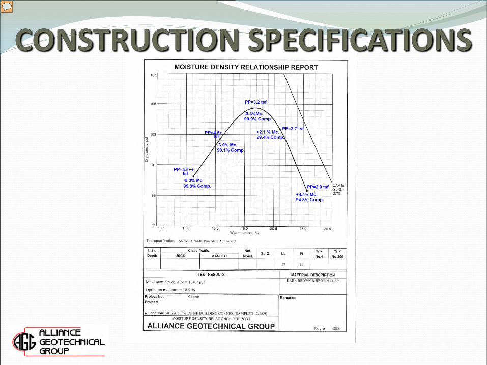
Presenter
Presentation Notes
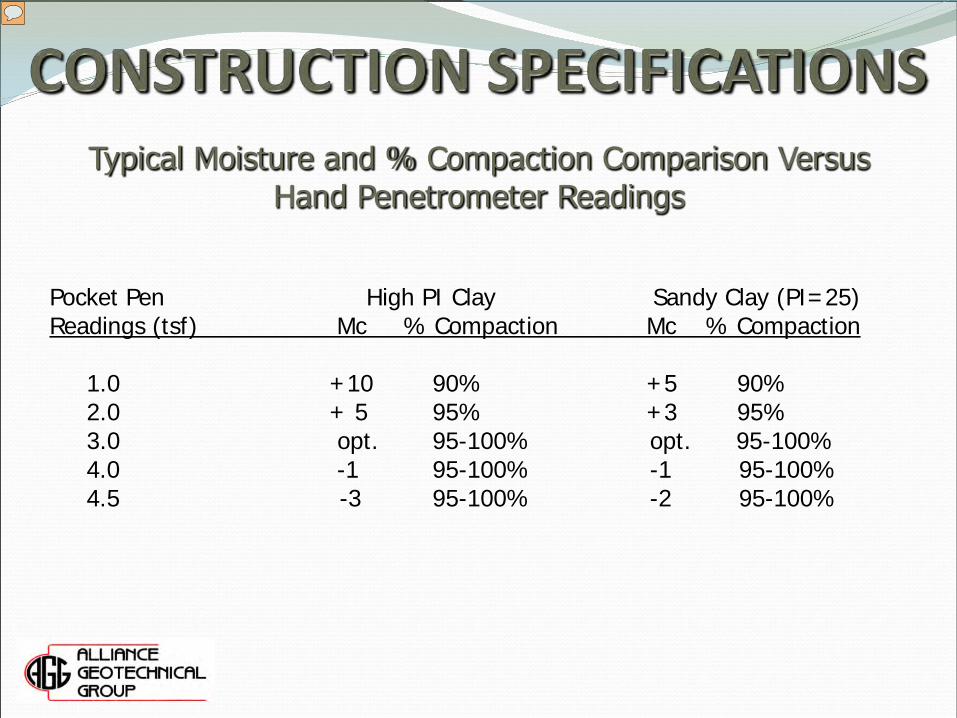
Proctor Correlations with Pocket Penetrometer -Pocket Pen each proctor points in lab to determine correlation
Typical Moisture and % Compaction Comparison Versus Hand Penetrometer Readings
Typical Correlation -Establish correlation in the lab Hand Penetrometer is to be used in clay not sand. Hand Penetrometer is QA/QC tool. It is not used to determine design parameters.
o Refer to a Geotechnical Engineer for foundation issues
o Plan Ahead – Make sure everyone is on the same page during the construction phase
o Have qualified and certified inspectors
o There are no dumb questions
Presenter
Presentation Notes
A certified inspector is not always qualified. Look at years of experience. There’s a difference between a technician with 10 years of experiences and a technician with ten 1 year experience. Questions should always be asked.