lessons learned to avoid coax cable failure in moving...
TRANSCRIPT
211
Lessons Learned to Avoid Coax Cable Failure in Moving Mechanical Mechanisms
Sheah Pirnack*
Abstract Several programs have experienced anomalies due to cold welding of coaxial cables within Moving Mechanical Assemblies. Cold welding occurs when similar clean adjacent metal surfaces (like silver on silver or gold on gold) molecularly bond to one another given sufficient cleanliness, time, and contact pressure; as the name implies, it can and will occur in the absence of heat. This paper addresses the effects of cold welding in coaxial cables, outlines specific test results, suggests how to test for cold welding, and how to avoid the problem of cold welding in the design and material selection phase of a program.
Introduction
Within moving mechanical assemblies (MMAs), where any item is expected to move relative to another, cold welding can result in failure or severe performance degradation. Cold welds create a constraint where either the cold weld is strong enough such that the two surfaces are unable to move relative to each other or where movement / strain on the surfaces will cause early fatigue failure (such as local yielding, buckling or other low cycle fatigue damage) when the cold welded joint is flexed.
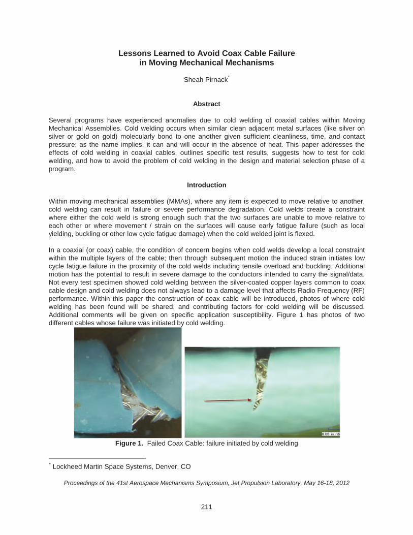
In a coaxial (or coax) cable, the condition of concern begins when cold welds develop a local constraint within the multiple layers of the cable; then through subsequent motion the induced strain initiates low cycle fatigue failure in the proximity of the cold welds including tensile overload and buckling. Additional motion has the potential to result in severe damage to the conductors intended to carry the signal/data. Not every test specimen showed cold welding between the silver-coated copper layers common to coax cable design and cold welding does not always lead to a damage level that affects Radio Frequency (RF) performance. Within this paper the construction of coax cable will be introduced, photos of where cold welding has been found will be shared, and contributing factors for cold welding will be discussed. Additional comments will be given on specific application susceptibility. Figure 1 has photos of two different cables whose failure was initiated by cold welding.
Figure 1. Failed Coax Cable: failure initiated by cold welding
* Lockheed Martin Space Systems, Denver, CO
Proceedings of the 41st Aerospace Mechanisms Symposium, Jet Propulsion Laboratory, May 16-18, 2012
212
Background
Within space flight Moving Mechanical Assemblies (MMA’s) the cabling design, construction, and management should be an integral part of the design process: the cable should be chosen for its RF/data/power performance, space-compatible materials, flexing capability, and the cable management system should consider the cables’ capability for bending through life without fatigue or instability compromising the functional integrity of the cable. When a coaxial cable is part of a MMA, specific features of the cable design as well as the mechanical features that manage the flexing and containment of the cable must be carefully considered. Insufficient attention to these mechanical design details can cause cold welding and/or subsequent fatigue failures in space hardware.
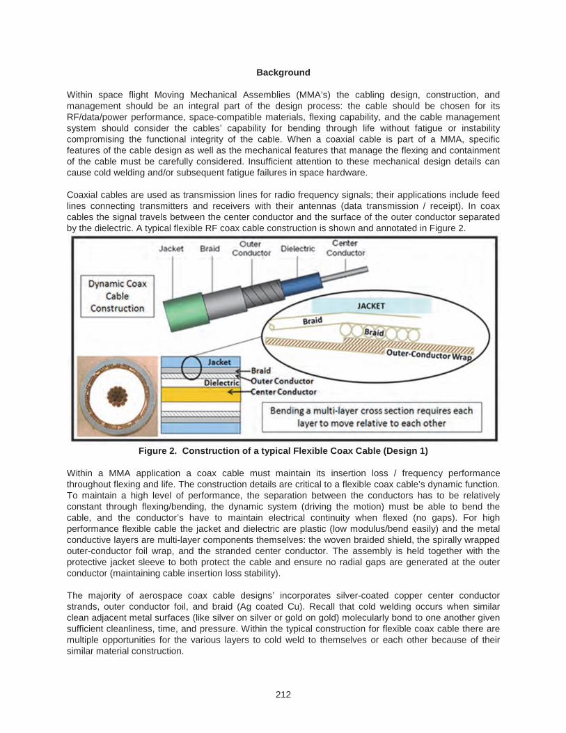
Coaxial cables are used as transmission lines for radio frequency signals; their applications include feed lines connecting transmitters and receivers with their antennas (data transmission / receipt). In coax cables the signal travels between the center conductor and the surface of the outer conductor separated by the dielectric. A typical flexible RF coax cable construction is shown and annotated in Figure 2.
Figure 2. Construction of a typical Flexible Coax Cable (Design 1)
Within a MMA application a coax cable must maintain its insertion loss / frequency performance throughout flexing and life. The construction details are critical to a flexible coax cable’s dynamic function. To maintain a high level of performance, the separation between the conductors has to be relatively constant through flexing/bending, the dynamic system (driving the motion) must be able to bend the cable, and the conductor’s have to maintain electrical continuity when flexed (no gaps). For high performance flexible cable the jacket and dielectric are plastic (low modulus/bend easily) and the metal conductive layers are multi-layer components themselves: the woven braided shield, the spirally wrapped outer-conductor foil wrap, and the stranded center conductor. The assembly is held together with the protective jacket sleeve to both protect the cable and ensure no radial gaps are generated at the outer conductor (maintaining cable insertion loss stability).
The majority of aerospace coax cable designs’ incorporates silver-coated copper center conductor strands, outer conductor foil, and braid (Ag coated Cu). Recall that cold welding occurs when similar clean adjacent metal surfaces (like silver on silver or gold on gold) molecularly bond to one another given sufficient cleanliness, time, and pressure. Within the typical construction for flexible coax cable there are multiple opportunities for the various layers to cold weld to themselves or each other because of their similar material construction.
213
Results of Testing
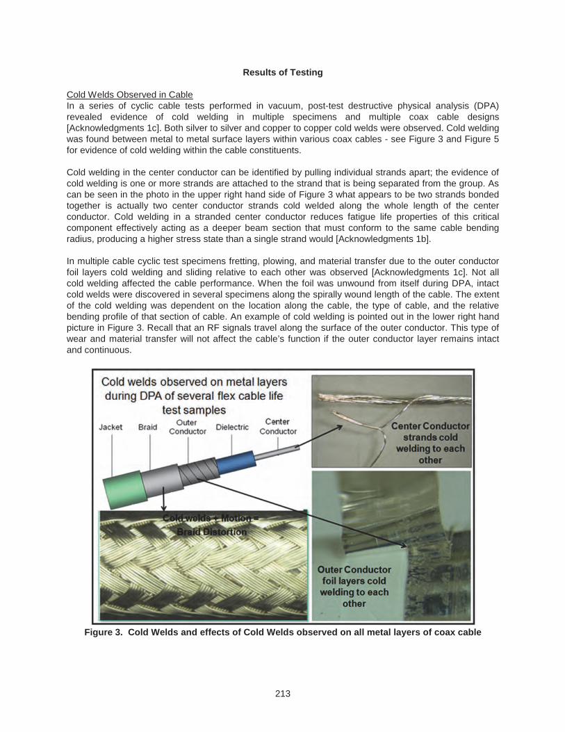
Cold Welds Observed in Cable In a series of cyclic cable tests performed in vacuum, post-test destructive physical analysis (DPA) revealed evidence of cold welding in multiple specimens and multiple coax cable designs [Acknowledgments 1c]. Both silver to silver and copper to copper cold welds were observed. Cold welding was found between metal to metal surface layers within various coax cables - see Figure 3 and Figure 5 for evidence of cold welding within the cable constituents.
Cold welding in the center conductor can be identified by pulling individual strands apart; the evidence of cold welding is one or more strands are attached to the strand that is being separated from the group. As can be seen in the photo in the upper right hand side of Figure 3 what appears to be two strands bonded together is actually two center conductor strands cold welded along the whole length of the center conductor. Cold welding in a stranded center conductor reduces fatigue life properties of this critical component effectively acting as a deeper beam section that must conform to the same cable bending radius, producing a higher stress state than a single strand would [Acknowledgments 1b].
In multiple cable cyclic test specimens fretting, plowing, and material transfer due to the outer conductor foil layers cold welding and sliding relative to each other was observed [Acknowledgments 1c]. Not all cold welding affected the cable performance. When the foil was unwound from itself during DPA, intact cold welds were discovered in several specimens along the spirally wound length of the cable. The extent of the cold welding was dependent on the location along the cable, the type of cable, and the relative bending profile of that section of cable. An example of cold welding is pointed out in the lower right hand picture in Figure 3. Recall that an RF signals travel along the surface of the outer conductor. This type of wear and material transfer will not affect the cable’s function if the outer conductor layer remains intact and continuous.
Figure 3. Cold Welds and effects of Cold Welds observed on all metal layers of coax cable
214
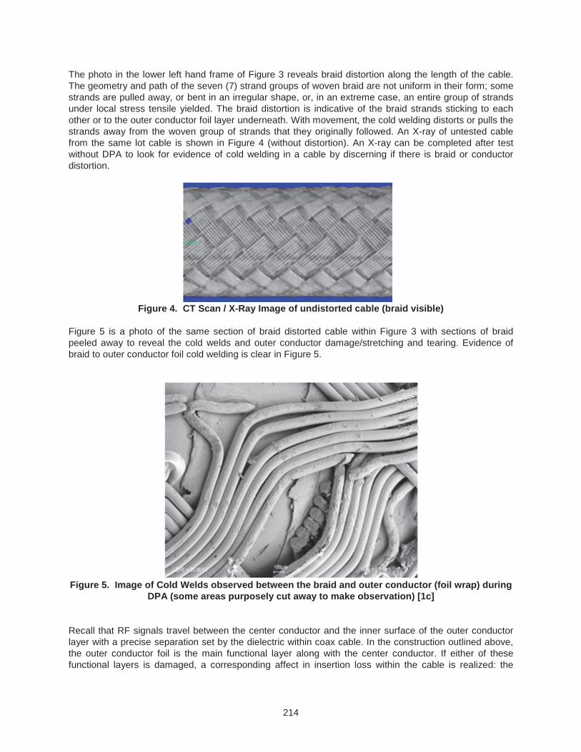
The photo in the lower left hand frame of Figure 3 reveals braid distortion along the length of the cable. The geometry and path of the seven (7) strand groups of woven braid are not uniform in their form; some strands are pulled away, or bent in an irregular shape, or, in an extreme case, an entire group of strands under local stress tensile yielded. The braid distortion is indicative of the braid strands sticking to each other or to the outer conductor foil layer underneath. With movement, the cold welding distorts or pulls the strands away from the woven group of strands that they originally followed. An X-ray of untested cable from the same lot cable is shown in Figure 4 (without distortion). An X-ray can be completed after test without DPA to look for evidence of cold welding in a cable by discerning if there is braid or conductor distortion.
Figure 4. CT Scan / X-Ray Image of undistorted cable (braid visible)
Figure 5 is a photo of the same section of braid distorted cable within Figure 3 with sections of braid peeled away to reveal the cold welds and outer conductor damage/stretching and tearing. Evidence of braid to outer conductor foil cold welding is clear in Figure 5.
Figure 5. Image of Cold Welds observed between the braid and outer conductor (foil wrap) during
DPA (some areas purposely cut away to make observation) [1c]
Recall that RF signals travel between the center conductor and the inner surface of the outer conductor layer with a precise separation set by the dielectric within coax cable. In the construction outlined above, the outer conductor foil is the main functional layer along with the center conductor. If either of these functional layers is damaged, a corresponding affect in insertion loss within the cable is realized: the
215
extent of insertion loss increase is dependent on the operational frequency range and the level of damage.
Susceptibility of Cold Welds in Cable: Choosing a flexible cable design Not every cable test sample showed cold welding between the silver coated copper layers, and not all cold welding led to damage that affected the RF performance of the cable. So what is the potential for damage due to the layers cold welding? And what kind of cold welding is most damaging? How can it be adequately screened for? And if a cable management system was successfully qualified and life tested already, is that enough, regardless of seemingly small changes between cable production lots?
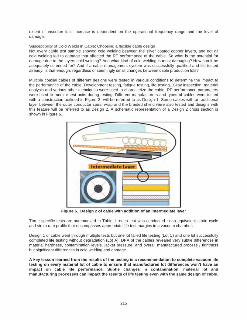
Multiple coaxial cables of different designs were tested in various conditions to determine the impact to the performance of the cable. Development testing, fatigue testing, life testing, X-ray inspection, material analysis and various other techniques were used to characterize the cable; RF performance parameters were used to monitor test units during testing. Different manufacturers and types of cables were tested with a construction outlined in Figure 2- will be referred to as Design 1. Some cables with an additional layer between the outer conductor spiral wrap and the braided shield were also tested and designs with this feature will be referred to as Design 2. A schematic representation of a Design 2 cross section is shown in Figure 6.
Figure 6. Design 2 of cable with addition of an intermediate layer
Three specific tests are summarized in Table 1: each test was conducted in an equivalent strain cycle and strain rate profile that encompasses appropriate life test margins in a vacuum chamber.
Design 1 of cable went through multiple tests but one lot failed life testing (Lot C) and one lot successfully completed life testing without degradation (Lot A). DPA of the cables revealed very subtle differences in material hardness, contamination levels, jacket pressure, and overall manufactured process / tightness but significant differences in cold welding and damage.
A key lesson learned from the results of the testing is a recommendation to complete vacuum life testing on every material lot of cable to ensure that manufactured lot differences won’t have an impact on cable life performance. Subtle changes in contamination, material lot and manufacturing processes can impact the results of life testing even with the same design of cable.
216
Table 1
Design 1: Lot A Design 1: Lot C Design 2
Baseline Construction / design 1: Lot A initial build & lot of materials, no performance affecting damage observed
Construction / Design 1 same as Lot A, different build date and lot of materials; Cold Welding and damage observed in multiple layers along length of cable
Design 2 incorporated intermediate layer, multiple Design 2 cables tested, Sporadic Cold Welding between Outer Conductor layer observed with minimal damage.
Life Tests Successful
(2 of 2 cables passed)
Life Tests Failed
(2 of 2 cables failed)
Life Test Successful
(6 of 6 cables passed)
Design 2 cables went through multiple tests, multiple permutations of profiles, and various other stress and fatigue tests in addition to the same level of testing of Design 1. Design 2 cable outperformed Design 1 cable. Two key features differentiate Design 2 Cable from the Design 1 cable: the intermediate non-silver coated copper layer between the outer conductor and the braided shield; and alloyed center conductor strands with a thicker outer silver coating. The failed Design 1 cable incorporated relatively pure copper strands coated with a thinner layer of silver within the center conductor strands.
In regard to cold welding, the intermediate layer prevents cold welding between the outer conductor and the braid by inserting a different material between the silver coated copper layers. This intermediate layer feature is believed to be the key difference preventing the most damaging occurrences of cold welds: cold welds that form between two separate layers in the outer portion of the cable. When the cable is put in bending, the outer layers are forced to move/slide relative to each other (more than the inner layers); if cold welds are present, instead of moving relative to each other by sliding, local yielding or pushing of surface materials occurs. Referring back to Figure 5, it is evident that braid to outer conductor cold welds initiated tearing and yielding in both layers through motion / bending of the cable.
The alloyed center conductor mitigates some level of the similar metal interaction required for cold welding, has better metal fatigue properties, and with a thicker layer of silver on each strand the silver is likely to transfer between strands acting as a lube or additional wear layer through plowing and compliance.
To mitigate the effects of cold welding in coaxial cables, the design and material of the cable for flexing applications should incorporate the two features mentioned:
1. Incorporate an intermediate layer between the outer conductor and braid of a different preferably non-metallic material. It will act as both a wear buffer and will prevent cold welding between the two outer most metallic layers of the cable. It also has the potential to mitigate insertion loss instability within cables (where the outer conductor loosens up over time developing a radial gap between adjacent wraps).
2. Ensure the center conductor is a higher strength alloyed copper and that the silver coating on the strands has a well controlled thickness (thicker likely is better based on the test observations).
Because of the many variables involved, a life test must be performed for each new design of cable even with the recommended features incorporated. In addition to design verification, an important lesson-learned was that coax cable construction and implementation can vary in subtle ways between production lots that can affect cold welding and fatigue capability, and therefore a life test should be performed for each production lot regardless of design similarity.
217
Monitoring RF Parameters for indicators to screen for a problem during Coax Cable Vacuum Testing During vacuum testing of the Design 1 lot C cable RF data (TDR, IL, & VSWR monitored continuously) indicated that something was happening almost immediately after a test pause due to a chamber issue. Up until that point there was no indication of a cable performance change. Similar pauses occurred with the other cable lots/designs but the leading indicator (RF performance) was unaffected.
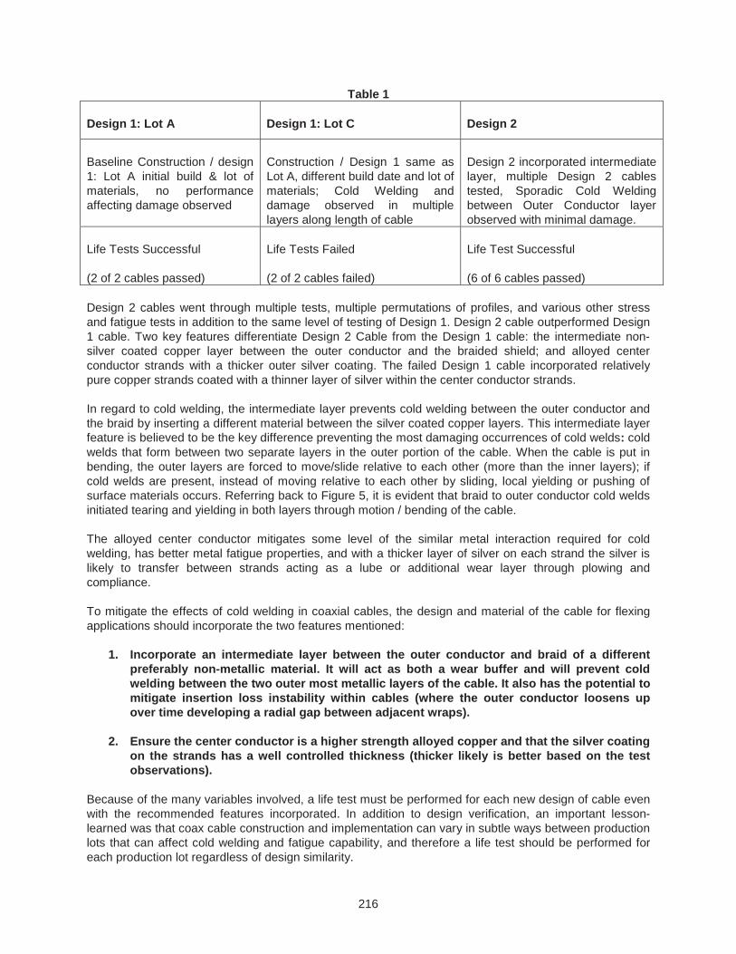
Soon after the restart of the test, the degradation of the Design 1 lot C cable was rapid. The initial indicator was a time-domain reflectometer (TDR) test where a discontinuity / spike identified damage in the bending portion of a cable. Through additional cycling an insertion loss “suck-out” or increase started to form in the highest monitored frequency range and moved towards the lower frequency ranges with additional cycles (RF performance monitored from 100 MHz – 20 GHz). The test was stopped to determine the cause of RF degradation. The RF performance was cable motion and position dependent indicating opening and closing of functional layers (impedance changes affecting loss). An in-situ x-ray inspection was completed with the test unit inside the vacuum chamber to determine the condition of the cable without incurring the risk of moving it. One of the x-rays images taken (courtesy of Aerospace Corporation) [Acknowledgments / Reference 2, 3] is shown in Figure 7. This x-ray happens to be same cable as shown in Figure 1 (left photo).
Figure 7. In-Situ X-Ray inspection photo taken of Test Unit in Chamber [2] reprinted with permission of The Aerospace Corporation
At the onset of the degradation the RF indicators implied a gap forming on the outer conductor functional layer (impedance change showing up as a TDR spike/ reflectance). Additional cycling caused the gap to propagate to a full circumferential crack around the cable and after a full breach was realized, additional cycling increased the separation along the length of the cable (gap grew larger). As the gap began to expand around the circumference of the cable, the insertion loss became evident in the higher frequency range and moved to the lower frequency ranges as the gap expanded and grew larger.
Based on bench-top testing completed at Lockheed Martin and repeated by Aerospace Corporation, (Acknowledgments 1a /References 2), the initiated crack would have had to have been at least 90 degrees circumferentially around the cable to show up in the highest frequency range (20 GHz). A crack development of 270 degrees about the circumference would impact the 10 GHz range. A full breach will
218
impact multiple frequency ranges with variable RF performance impacts dependent on the cable geometry, conductor condition, bending requirements, size of the gap, etc.. The bench-top testing completed at Lockheed Martin [Acknowledgments 1a] and Aerospace Corporation [2] mapped the rapid physical degradation to the RF indicators.
Prior to the significant RF degradation resulting from the damage as shown in Figure 7, there was no warning of an issue in the cable. Unfortunately this means if you can see a change in the RF, an issue is likely already present indicating some level of damage to the cable. There is no leading indicator of actual cold welding in the RF data until the damage is done. The effect of the cold welding condition occurs after a cable is moved and the damage is within the active cable layers. RF position dependent performance was due to the breach in the outer conductor foil layer opening (higher impedance) when bending the cable and closing (recovering) by reversing the bending / motion.
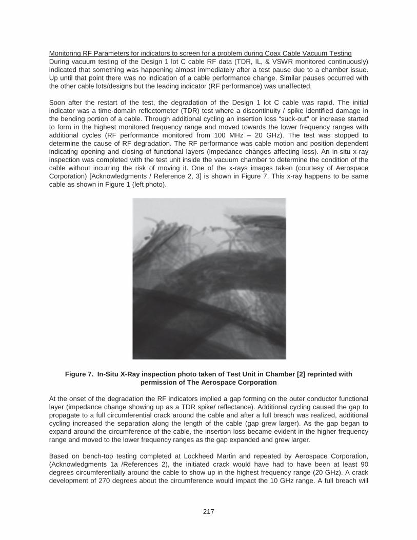
On a similar Design 1 Lot C cable, a partial breach of the outer conductor manifested itself in a similar manner, but was in a much lower strain area. Prior to DPA, a CT scan of the break area (this cable did not have a full circumferential break) was completed. The CT scan revealed that the center conductor had failed. The center conductor strands appear to have failed due to accelerated fatigue caused by increased bending from a partial breach. A likely contributor to the accelerated fatigue in the cable is an adjacent stiffness increase due to cold welded cable layers. The CT scan image of the break area is shown in Figure 8 as a section view so that the center conductor is visible; this image is of the same cable as shown in Figure 1 (right photo).
Figure 8. CT Scan inspection photo taken of a partially breached cable with center conductor condition shown (part of outer conductor / shield taken out of visible frame)
As can be inferred from the photos of damaged cables and the trailing RF indicator, it is imperative to test cables well to screen for this condition.
Experience has shown that cold welding has led to a progressive damage process and, while not proven experimentally, cumulative fatigue damage is expected to be a non-linear function of cyclic flexural amplitude times the number of cycles typical of metallic fatigue. Consequently, the design of the coax cable and the cable management system must be within proven fatigue capabilities for an expected mission angular movement profile [Acknowledgments 1b].
219
Possible contributors and/or additional areas of concern References on cold welding indicate time is necessary for cold welds to form. Although it does not take very long for cold welds to form, continuously running a test without pausing has been shown in past tests to prevent cold welds from occurring. It is believed that in the test with the Design 1 Lot C cable that material conditions were right within the cable layers to cause cold welds, the time and opportunity was given in the test pause, and after restarting the test and inducing motion on the cold welded cable the damage progressed to a severe level. Completing a cable test continuously without pauses impacts the cable layers ability to cold weld, potentially masking an issue in the cable. Mechanism idle periods during a mission promotes the development of cold welds (to become more prominent or stronger), in effect accelerating the degradation in the cable when mechanism operation resumes. Complete cable testing as flight-like as possible to ensure that the operation and stopping or non-operation is adequately simulated. Conversely if the application requires the cable to continually move this may actually prevent severe cold welds from occurring.
Several vacuum life tests were run with Design 2 test cables. The most apparent advantage of the intermediate layer to cable performance is preventing the braid to outer conductor cold welding. It does not, however, prevent the various layers from cold welding to themselves (outer conductor wrap to adjacent outer conductor wrap or braid to itself). Some Design 2 cables were tested with a profile consistent with the other test units but with small angle dithers incorporated at each extreme (while similar cables did not undergo the small angle dithers). These dithers were not analytical contributors to fatigue so were not initially considered to affect the overall performance of the cable, but they did, however, have an effect on the condition of the cable noted in DPA. The cables that had small angle dithers incorporated into their test profile had cold welding between the outer conductors foil layers (lower right picture on Figure 3). The cold welds within the Design 2 test cable did not impact the RF performance of that specific cable but their significance in a design susceptible to multilayer cold welding may be severe. What was concluded from this result is that small angle motion likely exacerbates cold welding as it contributes to cleaning the surface between the metals (but is not necessary for cold welding to occur if the surfaces are already clean). Small angle dithers, although not a large contributor to fatigue can polish a surface, pushing barrier films away and cleaning the surfaces through movement. What is also theorized is that the cold welding did not impact the performance because it was only between the outer conductor and itself and not between the outer conductor and the braid. The motion that was being stifled at the sporadic cold welds between the outer conductors was made up for with adjacent wraps and layer motion.
Clearly the speed/motion profile used in the life test significantly affects the results of the life test. However a surprising result of the investigation indicated that the cables that were vacuum life tested at slower speeds, with pausing and dithers incorporated within the profile (versus a generic encompassing designed profile simulating accelerated cumulative fatigue) degraded more rapidly (with less motion and cycles). Understanding the subtle parameters of a critical contact surface is essential to make informed decisions on how to design a life test given typical time considerations. Critical interfaces should be tested in as flight like manner as possible (Test like you fly).
It has been asked whether a vacuum environment is necessary for cold welding to occur. In the testing completed during this investigation, cold welding in cables was observed for cables tested both vacuum and atmospheric conditions; however all of the critical testing for our investigation was completed inside a vacuum chamber. All DPA activities were performed under ambient laboratory conditions. It is believed by the author that the space vacuum environment exacerbates the condition of cold welding simply because it is a cleaner environment and without air to replenish a potential contamination source (ex. oxidation, nitrides, and water), cold welding is more likely to occur. One test result, although not statistically significant, between two similar cable specimens demonstrated that cold welding occurred more readily in the specimen tested in a vacuum environment (sooner within a similar cyclic test profile) versus the test specimen run in ambient laboratory conditions. Two previously published papers on cold welding within cables [4,5] also mention the affect of vacuum on cold welding.
220
Given sufficient time and pressure, two metals of similar composition in clean contact will form cold welds.
Applications of concern Depending on the amount of motion required of the cable, cold welds may or may not be a problem. Depending on the geometry of the system, fatigue may or may not be an issue, but additional consideration to local low cycle fatigue of layers due to cold welding should be given. If cold welds form and the cables are not required to move during operation, then cold welding is not a concern. The following are application considerations regarding cold welding to keep in mind throughout the design, verification, or qualification life cycle of a program or MMA design:
Cables in or across single deployment mechanisms are generally NOT at risk:
Cable primary failure mode is fatigue (yielding and buckling). Cold welds reduce the number of cycles / amount of motion required for local fatigue failure to occur. Single deployment mechanisms that have to operate once will not generally have excessive cumulative damage from fatigue (even low cycle local fatigue).
Deployments generally occur at beginning of life (BOL). With relatively little time / motion relative to last “successful on-ground” test, damage from cold welds likely will not have the chance propagate to a failure within a single motion / deployment.
However:
If the system has low force / torque margins there is some risk of higher force required to move / bend cable relative to what was tested initially if cold welds formed post launch / pre-deployment.
If cold welds form prior to deployment and a very large motion/bending is required for the initial / first and only motion some damage might occur at deployment. The likelihood of cold welds forming and cumulative damage in one motion is low but should be considered in the context of the application.
Cables that are expected to operate and move over life (especially high cycle long life mechanisms) ARE at risk:
Dithering motion and vibration can exacerbate cold welds by abrading the surfaces and creating atomically clean surfaces. A space vacuum environment also contributes to maintaining clean surfaces.
Pausing, idle periods and non-operation between operation / motion cycles can exacerbate cold welds by allowing the two adjacent surfaces time to molecularly bond to one another and form stronger cold weld bonds.
Bending the cable through any angular motion has the potential to cause damage to the layers within the cable particularly when the layers have cold welded or are sensitive to fatigue failure; but not all damage is life threatening - the cold welds’ strength, the forced strain on the layers and the fatigue properties of the individual cold welded cable materials will determine the extent of the damage.
Through multiple cycles of cold welded cables the extent of the damage becomes progressively greater and can lead to a full break / breach in a cable.
221
Aside from cables, the risks may be obvious, but it is worth mentioning that similar metal to metal contact interfaces requiring motion within mechanisms are at risk.
If two surfaces are required to move relative to each other and there is no (non-metallic) barrier between them (lube, coating or otherwise) then cold welding can lead to failure (seizure / increased force to slide, move or separate; or low cycle fatigue) at that joint / interface.
Any critical surface contact and motion between critical interfaces should be tested in as flight like manner as possible (Test Like You Fly). Recall cold welding is exacerbated by clean surfaces, time, and contact pressure, so ensure testing incorporates / encompasses these critical parameters.
Dithering motion and vibration can exacerbate cold welds by abrading the surfaces and exposing the atomically clean metallic surfaces underneath. A space vacuum environment also contributes to maintaining clean surfaces (no oxidation, sulfides, water vapor, etc) – Test like you fly considerations should be validated.
Pausing, idle periods and non-operation between operation / motion cycles can exacerbate cold welds by allowing the two adjacent surfaces time to molecularly bond to one another and form stronger cold welds. Sequence of initialization, deployments, and storage periods should be given consideration during a qualification of critical contact surfaces.
A higher contact pressure and softer metallic interface contribute to a larger contact surface area and more energy at the interface to encourage the metals to share molecules, i.e., the higher the likelihood of cold welding. Reference 5 goes into further detail about the contribution of surface micro hardness of the constituents as it relates to cold welding.
Material Lot Changes: Hardness, contamination/cleanliness, alloy/material difference, subtle construction differences/ machine and assembly setups all make a difference and should be considered when making a decision on whether cold welding is a concern in your system. Complete a life test on every lot of material for critical surfaces whether or not you have completed a life test in one version or design.
Conclusion
Moving cables are sensitive to changes in material lot and test parameters including vacuum, strain / motion, speed, and other test like you fly assumptions much like other components within moving mechanical assemblies. This was the conclusion after a multiple year investigation completed on coaxial cable for an aerospace Moving Mechanical Assembly. Fatigue has been widely discussed as the primary failure mode of flexing wire; however, other phenomena need to be considered when designing a cable to move over life. Cold welding, a condition in which welds occurs between similar metals in the absence of heat, can occur on cable layers if precautions are not put in place when choosing a cable design to use for a moving application. For coax cable it has been shown that cold welding between the outer braid and the outer conductor can lead to degradation in RF performance. Three key points were discussed during the course of this paper:
1. Life Test Programs are not usually driven by lot/date code changes, however, life testing for coax cable from each production lot is recommended
2. Coax Cable Designs to be used in life critical MMA’s should incorporate a non-metallic intermediate layer to prevent multi-layer cold welding between any metal to metal layers. Additional attention should be paid to the lot construction of the individual metal constituents
222
including the center conductor. Ensure the center conductor is an alloyed copper (higher strength) and that the silver coating on the strands has a well controlled thickness (thicker likely is better based on the test observations).
3. Cold Welding happens with clean metal to metal contact. These lessons learned are applicable to other Moving Mechanical Assembly (MMA) components where sliding or rolling interfaces are metal to metal. Testing should simulate flight like conditions, sequences, and profiles to the maximum extent possible on any MMA especially considering the entire variable set that could potentially affect performance.
Acknowledgments
(1) Lockheed Martin Space Systems (LMSSC) Data, Assessments from Team, and Findings:
a. Special credit goes to the RF Engineers for their extensive coax cable knowledge and testing
b. Analysis Group for their analysis expertise in macro and micro structures, metal stress/strain, fatigue and dynamic simulation work
c. Failure Analysis Lab for steady hands and patience dissecting tens and hundreds of cable specimens (DPA work) and documenting it beautifully.
Additional acknowledgements on the LM Team in Denver: Quality Lab for scanning and rendering all the CT scan cable images, and many more folks on the team that put in countless hours and thought ensuring our results were something we could rely on. Thanks to the whole Lockheed Martin, LM Customer, Aerospace Corporation, and Subcontractor Team for providing their time, resources, test samples, and units from which we gathered a lot of data and knowledge.
(2) Also special mention of Bob/Robert Pan from Aerospace Corporation for being a facilitator of information transfer ensuring the contractor / customer and Aerospace team were in constant communication and providing additional data with Aerospace Corporation support through repeating tests for confirmation, refinement, and interpretation of results.
References
(3) 2D In-situ X-Ray Image (Figure 7) courtesy of The Aerospace Corporation, Dr. Eric C. Johnson, Shant Kenderian, and Robert Pan, Space Material Laboratory.
Published Papers on Cold Welding:
(4) Coaxial Cable Failure in a Spacecraft Mechanism, by Michael Chiu, Proceedings of the 34th Aerospace Mechanisms Symposium, Goddard Space Flight Center, May 10-12, 2000 where the solution for cold welding in cables was to replace design with a design that had a PTFE barrier between the wire braid and foil
(5) Material Property Effects on Coaxial Cable Mechanical Failure, by R. B. Pan, J.B. Chang, C.C. Wan, Y. R. Takeuchi, R. McVey, and I. Chen Proceeding of the 36th Aerospace Mechanisms Symposium, Glenn Research Center, May 15-17, 2002 where it shows DPA results and postulates a failure mechanism that relates low yield strength associated with the low hardness values to the cold welding of similar material at the interface, rapid initiation of multiple crack sites and fast crack propagation.
(6) Assessment of Cold Welding Between Separable Contact Surfaces Due to Impact and Fretting Under Vacuum; by A. Merstallinger, M. Sales, E. Semerad, Austrian Institute of Technology, and B.D. Dunn, ESA/ESTEC European Space Agency; STM-279, November 2009.