lesson12 recovery architectures
TRANSCRIPT

Lesson 12: Recovery System
DBMS Architectures
Lesson 12 / Page 2 AE3B33OSD Silberschatz, Korth, Sudarshan S. ©2007
Contents
Recovery after transactions failure
Data access and physical disk operations
Log-Based Recovery
Checkpoints
Recovery With Concurrent Transactions
Database Buffering
Database System Architectures
Client-Server Systems
Transaction Servers
Parallel Systems
Distributed Systems
Lesson 12 / Page 3 AE3B33OSD Silberschatz, Korth, Sudarshan S. ©2007
Failure Classification
Transaction failure : Logical errors: transaction cannot complete due to some internal
error condition
System errors: the database system must terminate an active transaction due to an error condition (e.g., deadlock)
System crash: a power failure or other hardware or software failure causes the system to crash. Fail-stop assumption: non-volatile storage contents are assumed
to not be corrupted by system crash Database systems have numerous integrity checks to prevent
corruption of disk data
Disk failure: a head crash or similar disk failure destroys all or part of disk storage Destruction is assumed to be detectable: disk drives use
checksums to detect failures
Lesson 12 / Page 4 AE3B33OSD Silberschatz, Korth, Sudarshan S. ©2007
Recovery Algorithms
In the previous lesson we mentioned highly inefficient shadow-database scheme Need for a better approach
Recovery algorithms are techniques to ensure database consistency and transaction atomicity and durability despite failures Focus of this chapter
Recovery algorithms have two parts 1. Actions taken during normal transaction processing to ensure
enough information exists to recover from failures
2. Actions taken after a failure to recover the database contents to a state that ensures atomicity, consistency and durability
Lesson 12 / Page 5 AE3B33OSD Silberschatz, Korth, Sudarshan S. ©2007
Storage Structure
Volatile storage: does not survive system crashes examples: main memory, cache memory
Nonvolatile storage: survives system crashes examples: disk, tape, flash memory,
non-volatile (battery backed up) RAM
Stable storage: a mythical form of storage that survives all failures approximated by maintaining multiple copies on distinct nonvolatile
media RAID – different levels of redundancy and fault tolerance
Lesson 12 / Page 6 AE3B33OSD Silberschatz, Korth, Sudarshan S. ©2007
Data Access
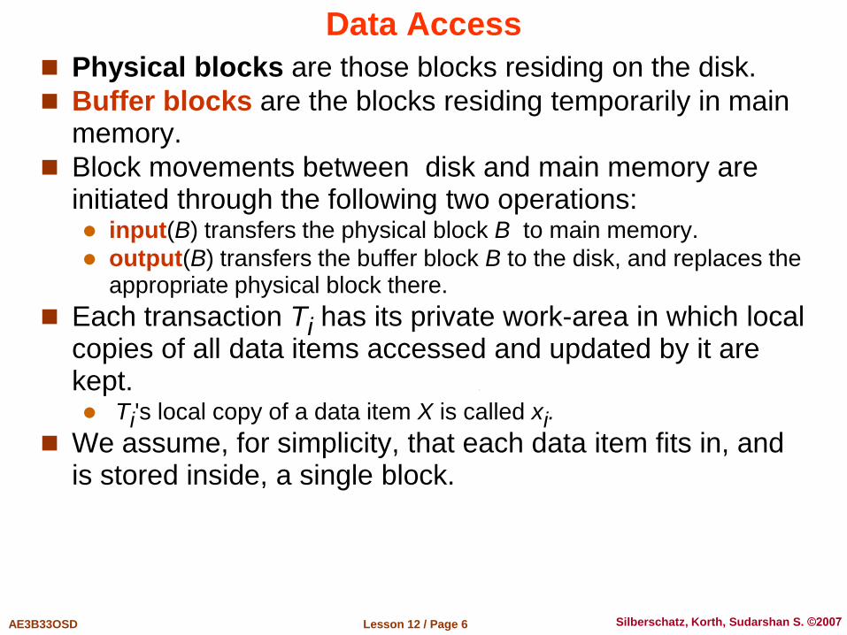
Physical blocks are those blocks residing on the disk.
Buffer blocks are the blocks residing temporarily in main memory.
Block movements between disk and main memory are initiated through the following two operations: input(B) transfers the physical block B to main memory.
output(B) transfers the buffer block B to the disk, and replaces the appropriate physical block there.
Each transaction Ti has its private work-area in which local copies of all data items accessed and updated by it are kept. Ti's local copy of a data item X is called xi.
We assume, for simplicity, that each data item fits in, and is stored inside, a single block.
Lesson 12 / Page 7 AE3B33OSD Silberschatz, Korth, Sudarshan S. ©2007
Data Access (Cont.)
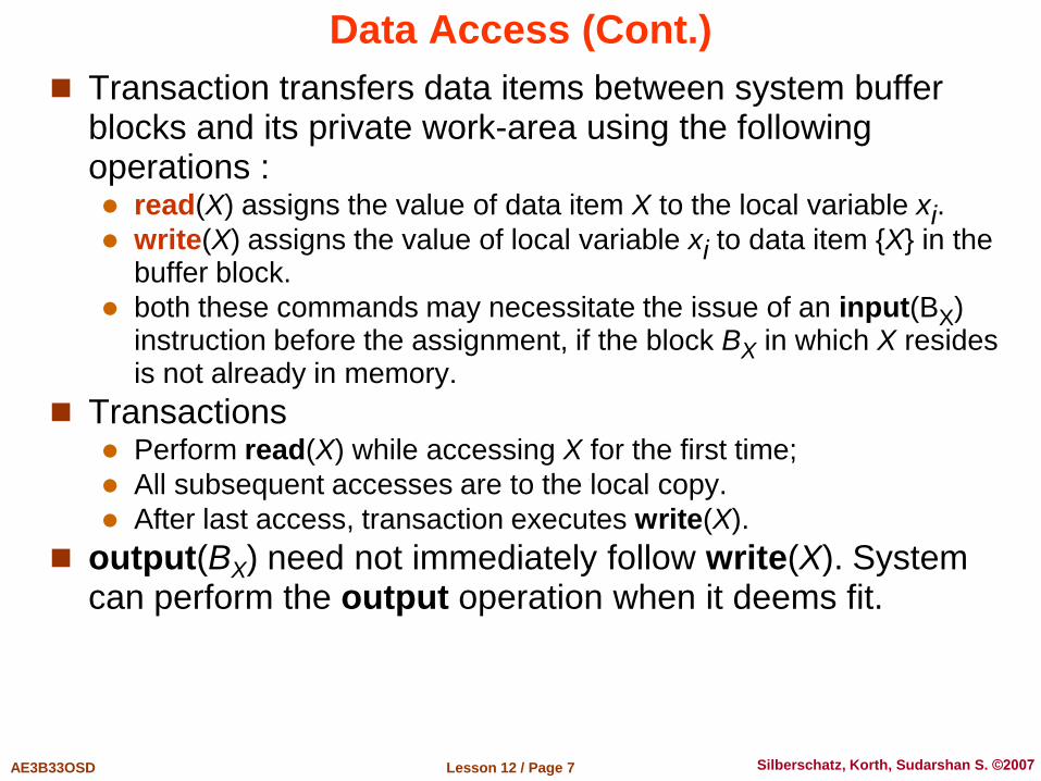
Transaction transfers data items between system buffer blocks and its private work-area using the following operations : read(X) assigns the value of data item X to the local variable xi.
write(X) assigns the value of local variable xi to data item {X} in the buffer block.
both these commands may necessitate the issue of an input(BX) instruction before the assignment, if the block BX in which X resides is not already in memory.
Transactions Perform read(X) while accessing X for the first time;
All subsequent accesses are to the local copy.
After last access, transaction executes write(X).
output(BX) need not immediately follow write(X). System can perform the output operation when it deems fit.
Lesson 12 / Page 8 AE3B33OSD Silberschatz, Korth, Sudarshan S. ©2007
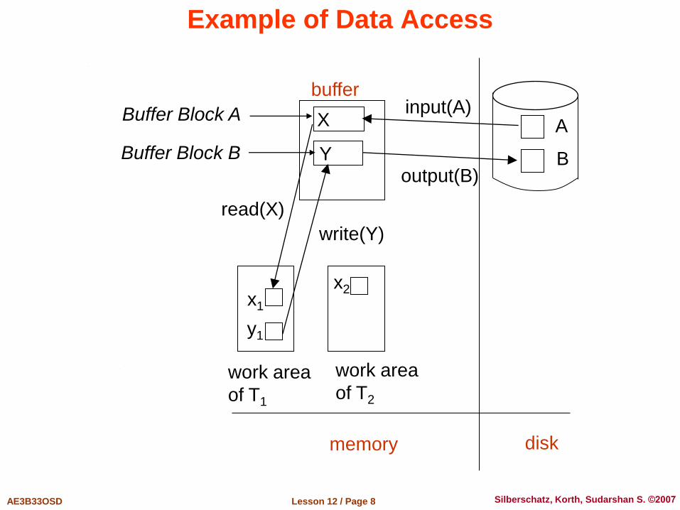
Example of Data Access
X
Y
A
B
x1
y1
buffer
Buffer Block A
Buffer Block B
input(A)
output(B)
read(X)
write(Y)
disk
work area
of T1
work area
of T2
memory
x2

Lesson 12 / Page 9 AE3B33OSD Silberschatz, Korth, Sudarshan S. ©2007
Recovery and Atomicity
Modifying the database without ensuring that the transaction will commit may leave the database in an inconsistent state.
Consider transaction Ti that transfers $50 from account A to account B; goal is either to perform all database modifications made by Ti or none at all.
Several output operations may be required for Ti (to output A and B). A failure may occur after one of these modifications have been made but before all of them are made
To ensure atomicity despite failures, we first output information describing the modifications to stable storage without modifying the database itself.
We will study two approaches: log-based recovery, and shadow-paging (block buffering)
We assume (initially) that transactions run serially, that is, one after the other.
Lesson 12 / Page 10 AE3B33OSD Silberschatz, Korth, Sudarshan S. ©2007
Log-Based Recovery
A log is kept on stable storage. The log is a sequence of log records, and maintains a record of
update activities on the database.
When transaction Ti starts, it registers itself by writing a <Ti start> log record
Before Ti executes write(X), a log record <Ti, X, V1, V2> is written, where V1 is the value of X before the write, and V2 is the value to be written to X. Log record notes that Ti has performed a write on data item Xj Xj
had value V1 before the write, and will have value V2 after the write
When Ti finishes it last statement, the log record <Ti commit> is written.
We assume for now that log records are written directly to stable storage (that is, they are not buffered)
Two approaches using logs Deferred database modification Immediate database modification
Lesson 12 / Page 11 AE3B33OSD Silberschatz, Korth, Sudarshan S. ©2007
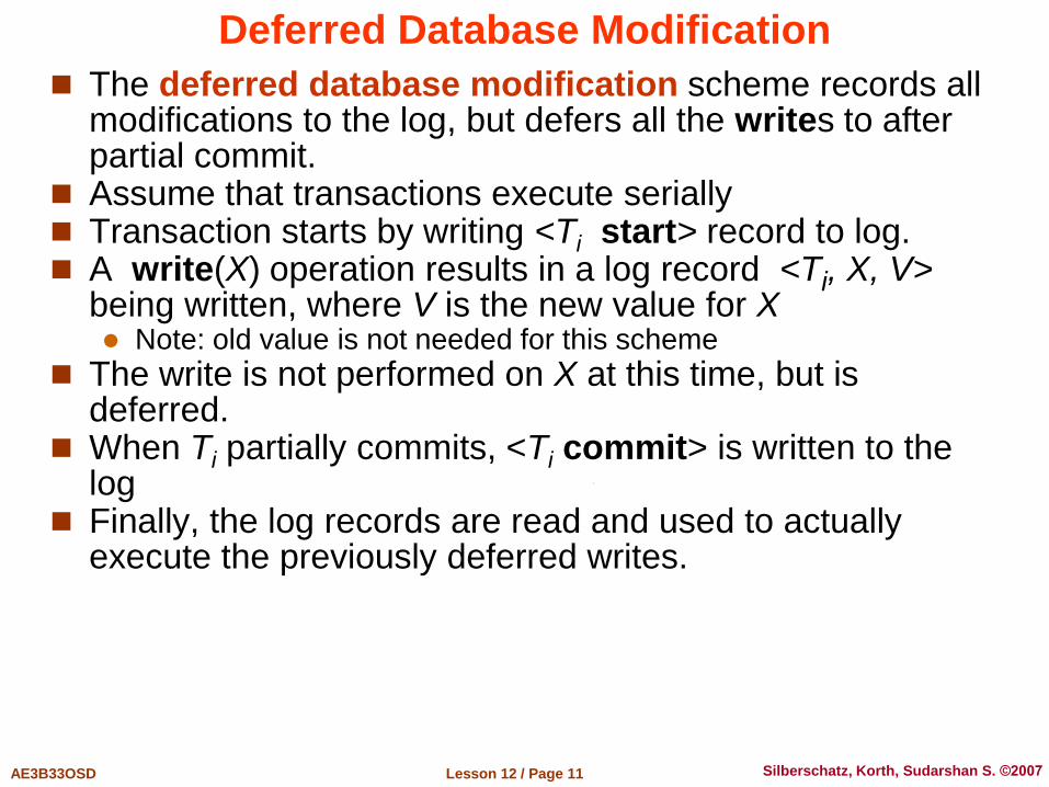
Deferred Database Modification
The deferred database modification scheme records all modifications to the log, but defers all the writes to after partial commit.
Assume that transactions execute serially Transaction starts by writing <Ti start> record to log. A write(X) operation results in a log record <Ti, X, V>
being written, where V is the new value for X Note: old value is not needed for this scheme
The write is not performed on X at this time, but is deferred.
When Ti partially commits, <Ti commit> is written to the log
Finally, the log records are read and used to actually execute the previously deferred writes.
Lesson 12 / Page 12 AE3B33OSD Silberschatz, Korth, Sudarshan S. ©2007
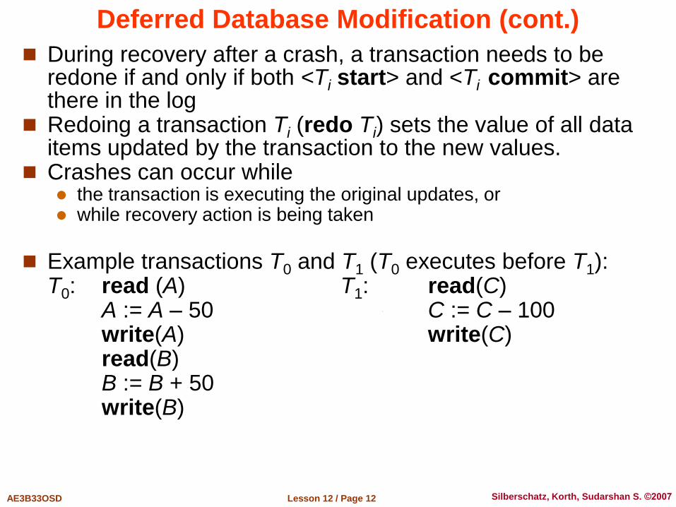
Deferred Database Modification (cont.)
During recovery after a crash, a transaction needs to be redone if and only if both <Ti start> and <Ti commit> are there in the log
Redoing a transaction Ti (redo Ti) sets the value of all data items updated by the transaction to the new values.
Crashes can occur while the transaction is executing the original updates, or while recovery action is being taken
Example transactions T0 and T1 (T0 executes before T1): T0: read (A) T1: read(C) A := A – 50 C := C – 100 write(A) write(C) read(B) B := B + 50 write(B)
Lesson 12 / Page 13 AE3B33OSD Silberschatz, Korth, Sudarshan S. ©2007
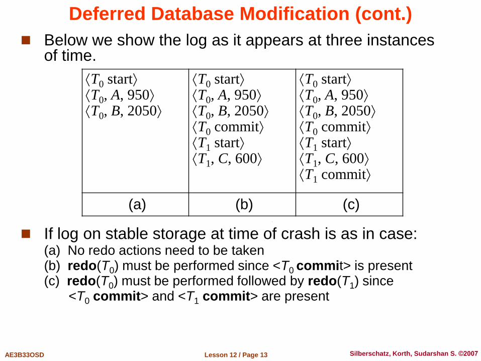
Below we show the log as it appears at three instances of time.
If log on stable storage at time of crash is as in case: (a) No redo actions need to be taken (b) redo(T0) must be performed since <T0 commit> is present (c) redo(T0) must be performed followed by redo(T1) since
<T0 commit> and <T1 commit> are present
Deferred Database Modification (cont.)
T0 start T0, A, 950 T0, B, 2050
T0 start T0, A, 950 T0, B, 2050 T0 commit T1 start T1, C, 600
T0 start T0, A, 950 T0, B, 2050 T0 commit T1 start T1, C, 600 T1 commit
(a) (b) (c)

Lesson 12 / Page 14 AE3B33OSD Silberschatz, Korth, Sudarshan S. ©2007
Immediate Database Modification
The immediate database modification scheme allows database updates of an uncommitted transaction to be made as the writes are issued since undoing may be needed, update logs must have both old
value and new value
Update log record must be written before database item is written We assume that the log record is output directly to stable storage Can be extended to postpone log record output, so long as prior to
execution of an output(B) operation for a data block B, all log records corresponding to items B must be flushed to stable storage
Output of updated blocks can take place at any time before or after transaction commit
Order in which blocks are output can be different from the order in which they are written.

Lesson 12 / Page 15 AE3B33OSD Silberschatz, Korth, Sudarshan S. ©2007
Immediate Database Modification Example
Log Write Output <T0 start> <T0, A, 1000, 950> <T0, B, 2000, 2050> A = 950 B = 2050 <T0 commit> <T1 start> <T1, C, 700, 600> C = 600 BB, BC <T1 commit> BA
Note: BX denotes block containing X

Lesson 12 / Page 16 AE3B33OSD Silberschatz, Korth, Sudarshan S. ©2007
Immediate Database Modification (cont.)
Recovery procedure has two operations instead of one: undo(Ti) restores the value of all data items updated by Ti to their
old values, going backwards from the last log record for Ti redo(Ti) sets the value of all data items updated by Ti to the new
values, going forward from the first log record for Ti
Both operations must be idempotent That is, even if the operation is executed multiple times, the effect is
the same as if it is executed once Needed since operations may get re-executed during recovery
When recovering after failure: Transaction Ti needs to be undone if the log contains the record
<Ti start>, but does not contain the record <Ti commit>. Transaction Ti needs to be redone if the log contains both the record
<Ti start> and the record <Ti commit>.
Undo operations are performed first, then redo operations

Lesson 12 / Page 17 AE3B33OSD Silberschatz, Korth, Sudarshan S. ©2007
Immediate DB Modification Recovery Example
Below we show the log as it appears at three instances of time.
Recovery actions in each case above are:
(a) undo(T0): B is restored to 2000 and A to 1000. (b) undo(T1) and redo(T0): C is restored to 700, and then A and B are
set to 950 and 2050 respectively. (c) redo(T0) and redo(T1): A and B are set to 950 and 2050
respectively. Then C is set to 600
T0 start T0, A, 1000, 950 T0, B, 2000, 2050
T0 start T0, A, 1000, 950 T0, B, 2000, 2050 T0 commit T1 start T1, C, 700, 600
T0 start T0, A, 1000, 950 T0, B, 2000, 2050 T0 commit T1 start T1, C, 700, 600 T1 commit
(a) (b) (c)

Lesson 12 / Page 18 AE3B33OSD Silberschatz, Korth, Sudarshan S. ©2007
Checkpoints
Problems in recovery procedures: 1. Searching the entire log is time-consuming
2. We might unnecessarily redo transactions which have already output their updates to the database.
Streamline recovery procedure by periodically performing checkpointing 1. Output all log records currently residing in main memory onto
stable storage.
2. Output all modified buffer blocks to the disk.
3. Write a log record <checkpoint> onto stable storage

Lesson 12 / Page 19 AE3B33OSD Silberschatz, Korth, Sudarshan S. ©2007
Checkpoints (cont.)
During recovery we need to consider only the most recent transaction Ti that started before the checkpoint, and transactions that started after Ti. 1. Scan backwards from end of log to find the most recent
<checkpoint> record 2. Continue scanning backwards till a record <Ti start> is found. 3. Need only consider the part of log following above start record.
Earlier part of log can be ignored during recovery, and can be erased whenever desired.
4. For all transactions (starting from Ti or later) with no <Ti commit>, execute undo(Ti). (Done only in case of immediate modification.)
5. Scanning forward in the log, for all transactions starting from Ti or later with a <Ti commit>, execute redo(Ti).
Lesson 12 / Page 20 AE3B33OSD Silberschatz, Korth, Sudarshan S. ©2007
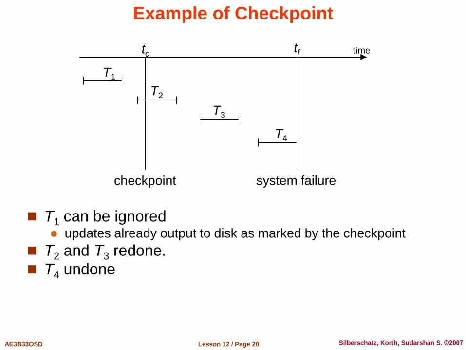
Example of Checkpoint
T1 can be ignored updates already output to disk as marked by the checkpoint
T2 and T3 redone.
T4 undone
tc tf
T1
T2
T3
T4
checkpoint system failure
time

Lesson 12 / Page 21 AE3B33OSD Silberschatz, Korth, Sudarshan S. ©2007
Recovery With Concurrent Transactions
We modify the log-based recovery schemes to allow multiple transactions to execute concurrently. All transactions share a single disk buffer and a single log A buffer block can have data items updated by one or more
transactions
We assume concurrency control using strict two-phase locking; i.e. the updates of uncommitted transactions should not be visible
to other transactions Otherwise how to perform undo if T1 updates A, then T2 updates A and
commits, and finally T1 has to abort?
Logging is done as described earlier. Log records of different transactions may be interspersed in the log.
The checkpointing technique and actions taken on recovery have to be changed since several transactions may be active when a checkpoint is
performed.

Lesson 12 / Page 22 AE3B33OSD Silberschatz, Korth, Sudarshan S. ©2007
Recovery With Concurrent Transactions (cont.)
Checkpoints are performed as before, except that the checkpoint log record is now of the form <checkpoint L>
where L is the list of transactions active at the time of the checkpoint We assume no updates are in progress while the checkpoint is
carried out (will relax this later)
When the system recovers from a crash, it first does the following: 1. Initialize undo-list and redo-list to empty 2. Scan the log backwards from the end, stopping when the first
<checkpoint L> record is found. For each record found during the backward scan: • if the record is <Ti commit>, add Ti to redo-list • if the record is <Ti start>, then if Ti is not in redo-list, add Ti to undo-list
3. For every Ti in L, if Ti is not in redo-list, add Ti to undo-list

Lesson 12 / Page 23 AE3B33OSD Silberschatz, Korth, Sudarshan S. ©2007
Recovery With Concurrent Transactions (cont.)
At this point undo-list consists of incomplete transactions which must be undone, and redo-list consists of finished transactions that must be redone.
Recovery now continues as follows: 1. Scan log backwards from most recent record, stopping when
<Ti start> records have been encountered for every Ti in undo-list. During the scan, perform undo for each log record that belongs to a
transaction in undo-list.
2. Locate the most recent <checkpoint L> record. 3. Scan log forwards from the <checkpoint L> record till the end of
the log. During the scan, perform redo for each log record that belongs to a
transaction on redo-list

Lesson 12 / Page 24 AE3B33OSD Silberschatz, Korth, Sudarshan S. ©2007
Log Record Buffering
Log record buffering for better performance Log records are buffered in main memory, instead of of being output
directly to stable storage. Log records are output to stable storage when a block of log records
in the buffer is full, or a log force operation is executed. Log force is performed to commit a transaction by forcing all its log
records (including the commit record) to stable storage.
Several log records can thus be output using a single output operation, reducing the I/O cost
The rules below must be followed if log records are buffered: Log records are output to stable storage in the order in which they
are created. Transaction Ti enters the commit state only when the log record
<Ti commit> has been output to stable storage. Before a block of data in main memory is output to the database, all
log records pertaining to data in that block must have been output to stable storage. This rule is called the write-ahead logging or WAL rule

Lesson 12 / Page 25 AE3B33OSD Silberschatz, Korth, Sudarshan S. ©2007
Database Buffering
Database maintains an in-memory buffer of data blocks When a new block is needed, if buffer is full an existing block needs
to be removed from buffer If the block chosen for removal has been updated, it must be output
to disk
If a block with uncommitted updates is output to disk, log records with undo information for the updates are output to the log on stable storage first (Write ahead logging)
No updates should be in progress on a block when it is output to disk. Can be ensured as follows: Before writing a data item, transaction acquires exclusive lock on
block containing the data item Lock can be released once the write is completed.
Such locks held for short duration are called latches.
Before a block is output to disk, the system acquires an exclusive latch on the block Ensures no update can be in progress on the block

Lesson 12 / Page 26 AE3B33OSD Silberschatz, Korth, Sudarshan S. ©2007
Buffer Management
Database buffer can be implemented either in an area of real main-memory reserved for the database, or in virtual memory
Implementing buffer in reserved main-memory has drawbacks: Memory is partitioned in advance between database buffer and
applications, limiting flexibility Requirements may change in time, and although operating system
knows best how memory should be divided up at any time, it cannot change the partitioning of memory
Lesson 12 / Page 27 AE3B33OSD Silberschatz, Korth, Sudarshan S. ©2007
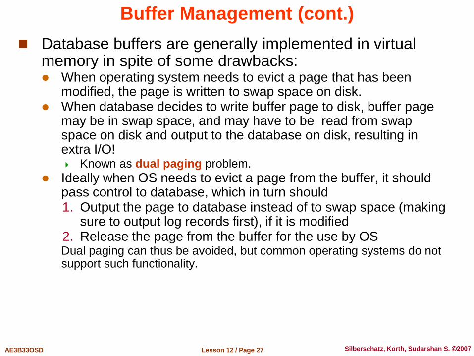
Buffer Management (cont.)
Database buffers are generally implemented in virtual memory in spite of some drawbacks: When operating system needs to evict a page that has been
modified, the page is written to swap space on disk. When database decides to write buffer page to disk, buffer page
may be in swap space, and may have to be read from swap space on disk and output to the database on disk, resulting in extra I/O! Known as dual paging problem.
Ideally when OS needs to evict a page from the buffer, it should pass control to database, which in turn should 1. Output the page to database instead of to swap space (making
sure to output log records first), if it is modified 2. Release the page from the buffer for the use by OS
Dual paging can thus be avoided, but common operating systems do not support such functionality.

ARIES Recovery Algorithm
Lesson 12 / Page 29 AE3B33OSD Silberschatz, Korth, Sudarshan S. ©2007
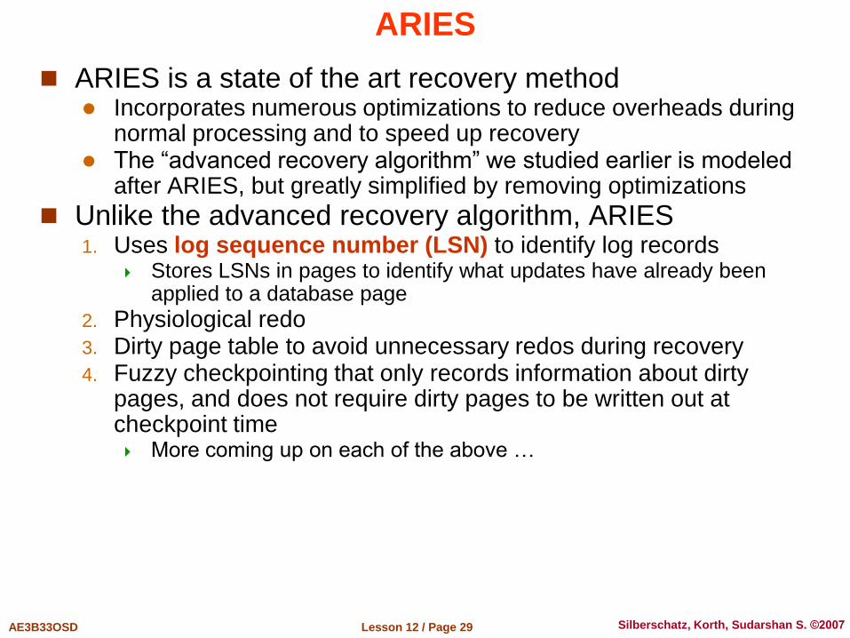
ARIES
ARIES is a state of the art recovery method Incorporates numerous optimizations to reduce overheads during
normal processing and to speed up recovery The “advanced recovery algorithm” we studied earlier is modeled
after ARIES, but greatly simplified by removing optimizations
Unlike the advanced recovery algorithm, ARIES 1. Uses log sequence number (LSN) to identify log records
Stores LSNs in pages to identify what updates have already been applied to a database page
2. Physiological redo 3. Dirty page table to avoid unnecessary redos during recovery 4. Fuzzy checkpointing that only records information about dirty
pages, and does not require dirty pages to be written out at checkpoint time More coming up on each of the above …

Lesson 12 / Page 30 AE3B33OSD Silberschatz, Korth, Sudarshan S. ©2007
ARIES Optimizations
Physiological redo Affected page is physically identified, action within page can
be logical Used to reduce logging overheads
– e.g. when a record is deleted and all other records have to be moved to fill hole » Physiological redo can log just the record deletion
» Physical redo would require logging of old and new values for much of the page
Requires page to be output to disk atomically – Easy to achieve with hardware RAID, also supported by some disk
systems – Incomplete page output can be detected by checksum techniques,
» But extra actions are required for recovery
» Treated as a media failure

Lesson 12 / Page 31 AE3B33OSD Silberschatz, Korth, Sudarshan S. ©2007
ARIES Data Structures
ARIES uses several data structures Log sequence number (LSN) identifies each log record
Must be sequentially increasing Typically an offset from beginning of log file to allow fast access
– Easily extended to handle multiple log files
Page LSN Log records of several different types Dirty page table
Lesson 12 / Page 32 AE3B33OSD Silberschatz, Korth, Sudarshan S. ©2007
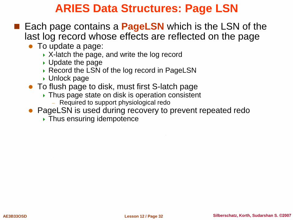
ARIES Data Structures: Page LSN
Each page contains a PageLSN which is the LSN of the last log record whose effects are reflected on the page To update a page:
X-latch the page, and write the log record Update the page Record the LSN of the log record in PageLSN Unlock page
To flush page to disk, must first S-latch page Thus page state on disk is operation consistent
– Required to support physiological redo
PageLSN is used during recovery to prevent repeated redo Thus ensuring idempotence
Lesson 12 / Page 33 AE3B33OSD Silberschatz, Korth, Sudarshan S. ©2007
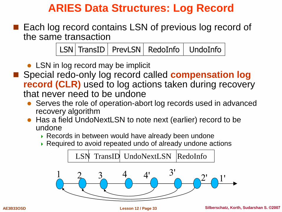
ARIES Data Structures: Log Record
Each log record contains LSN of previous log record of the same transaction LSN in log record may be implicit
Special redo-only log record called compensation log record (CLR) used to log actions taken during recovery that never need to be undone Serves the role of operation-abort log records used in advanced
recovery algorithm Has a field UndoNextLSN to note next (earlier) record to be
undone Records in between would have already been undone Required to avoid repeated undo of already undone actions
LSN TransID PrevLSN RedoInfo UndoInfo
LSN TransID UndoNextLSN RedoInfo
1 2 3 4 4' 3' 2' 1'
Lesson 12 / Page 34 AE3B33OSD Silberschatz, Korth, Sudarshan S. ©2007
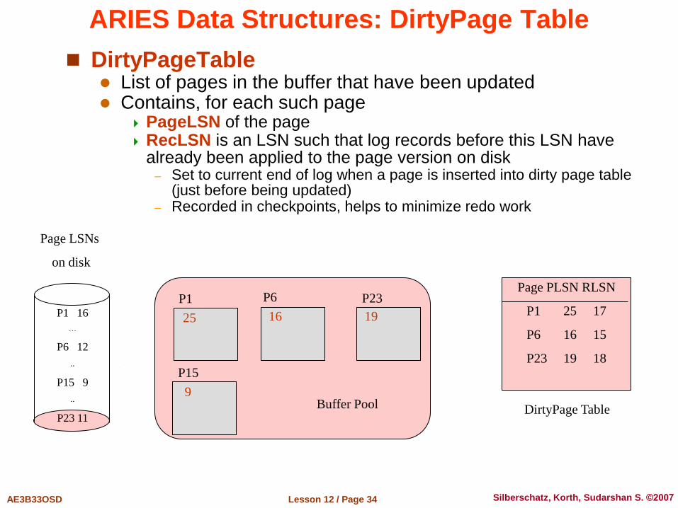
ARIES Data Structures: DirtyPage Table
DirtyPageTable List of pages in the buffer that have been updated Contains, for each such page
PageLSN of the page RecLSN is an LSN such that log records before this LSN have
already been applied to the page version on disk – Set to current end of log when a page is inserted into dirty page table
(just before being updated) – Recorded in checkpoints, helps to minimize redo work
Page PLSN RLSN
P1 25 17
P6 16 15
P23 19 18
25
P1
16
P6
19
P23
DirtyPage Table
9
P15
Buffer Pool
P1 16
…
P6 12
..
P15 9
..
P23 11
Page LSNs
on disk
Lesson 12 / Page 35 AE3B33OSD Silberschatz, Korth, Sudarshan S. ©2007
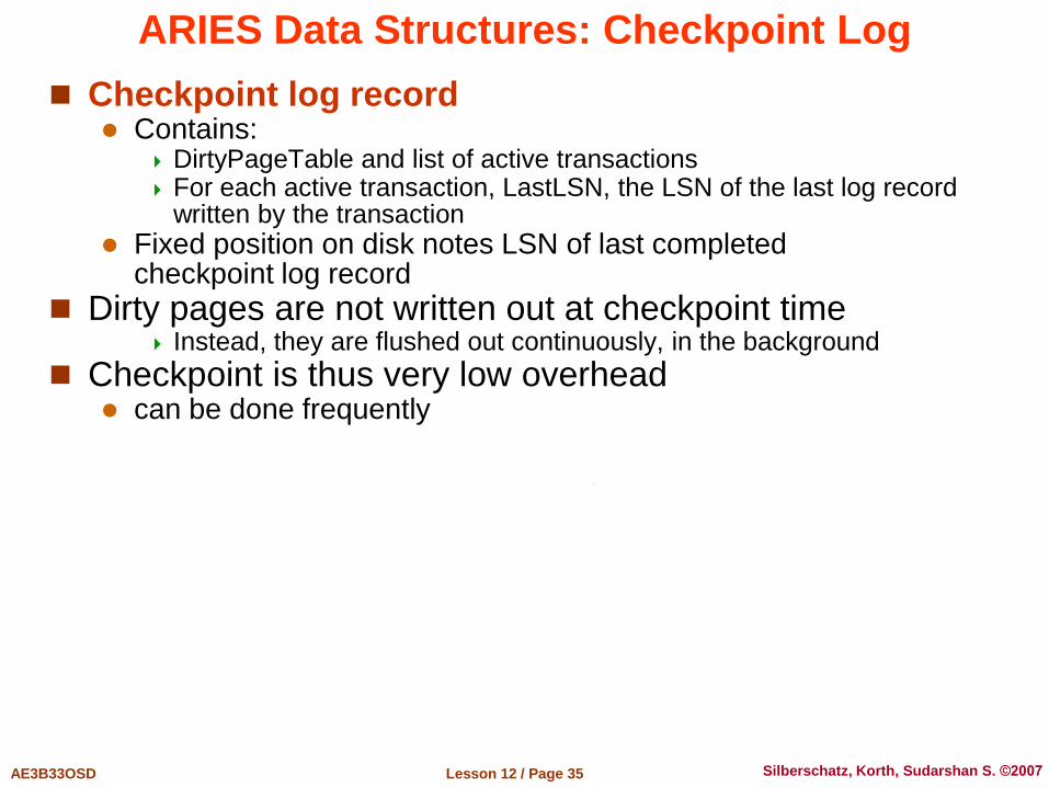
ARIES Data Structures: Checkpoint Log
Checkpoint log record Contains:
DirtyPageTable and list of active transactions For each active transaction, LastLSN, the LSN of the last log record
written by the transaction
Fixed position on disk notes LSN of last completed checkpoint log record
Dirty pages are not written out at checkpoint time Instead, they are flushed out continuously, in the background
Checkpoint is thus very low overhead can be done frequently

Lesson 12 / Page 36 AE3B33OSD Silberschatz, Korth, Sudarshan S. ©2007
ARIES Recovery Algorithm
ARIES recovery involves three passes Analysis pass: Determines
Which transactions to undo Which pages were dirty (disk version not up to date) at time of
crash RedoLSN: LSN from which redo should start
Redo pass: Repeats history, redoing all actions from RedoLSN
RecLSN and PageLSNs are used to avoid redoing actions already reflected on page
Undo pass: Rolls back all incomplete transactions
Transactions whose abort was complete earlier are not undone – Key idea: no need to undo these transactions: earlier undo actions
were logged, and are redone as required
Lesson 12 / Page 37 AE3B33OSD Silberschatz, Korth, Sudarshan S. ©2007
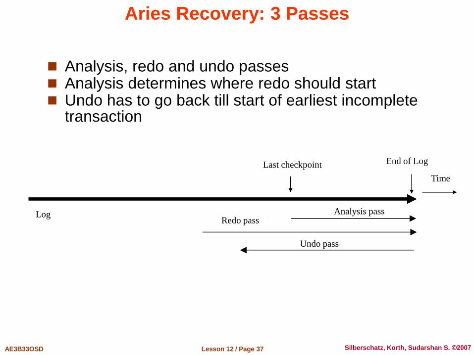
Aries Recovery: 3 Passes
Analysis, redo and undo passes Analysis determines where redo should start Undo has to go back till start of earliest incomplete
transaction
Last checkpoint
Log
Time
End of Log
Analysis pass Redo pass
Undo pass
Database System Architectures

Lesson 12 / Page 39 AE3B33OSD Silberschatz, Korth, Sudarshan S. ©2007
Centralized Systems
Run on a single computer system and do not interact with other computer systems
Centralized databases run on a general-purpose computer system with one or few CPUs
Everything in the database is executed locally. There is no or very low degree of concurrency Database technologies described in this course are used to speed-
up data access, only
Examples include simple single-user accounting systems inventory management in a small shop with just one cash desk management of CD’s in your home
Importance of such systems is very low from the DBMS point of view
Lesson 12 / Page 40 AE3B33OSD Silberschatz, Korth, Sudarshan S. ©2007
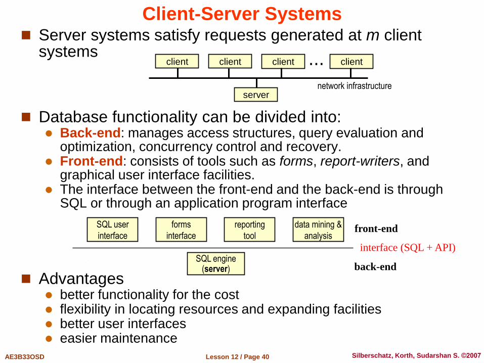
Client-Server Systems Server systems satisfy requests generated at m client
systems
Database functionality can be divided into: Back-end: manages access structures, query evaluation and
optimization, concurrency control and recovery. Front-end: consists of tools such as forms, report-writers, and
graphical user interface facilities. The interface between the front-end and the back-end is through
SQL or through an application program interface
Advantages better functionality for the cost flexibility in locating resources and expanding facilities better user interfaces easier maintenance
client client client client ...
server network infrastructure
SQL user
interface
forms
interface
reporting
tool
data mining &
analysis
SQL engine (server)
interface (SQL + API)
front-end
back-end

Lesson 12 / Page 41 AE3B33OSD Silberschatz, Korth, Sudarshan S. ©2007
Server System Architecture
Server systems can be broadly categorized into two kinds: transaction servers which are widely used in relational database
systems, and
data servers, used in object-oriented database systems
We treat here transaction servers, only, as object-oriented database systems were not discussed in this course

Lesson 12 / Page 42 AE3B33OSD Silberschatz, Korth, Sudarshan S. ©2007
Transaction Servers
Also called query server systems or SQL server systems Clients send requests to the server Transactions are executed at the server Results are shipped back to the client.
Requests are specified in SQL, and communicated to the server through a remote procedure call (RPC) mechanism
Transactional RPC allows many RPC calls to form a transaction
Open Database Connectivity (ODBC) is a C language application program interface (API) standard from Microsoft for connecting to a server, sending SQL requests, and receiving results.
JDBC standard is similar to ODBC, for Java developed by Sun Microsystems
Lesson 12 / Page 43 AE3B33OSD Silberschatz, Korth, Sudarshan S. ©2007
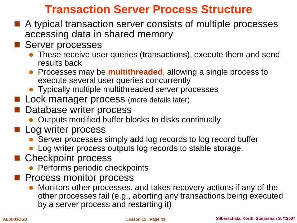
Transaction Server Process Structure
A typical transaction server consists of multiple processes accessing data in shared memory
Server processes These receive user queries (transactions), execute them and send
results back Processes may be multithreaded, allowing a single process to
execute several user queries concurrently Typically multiple multithreaded server processes
Lock manager process (more details later)
Database writer process Outputs modified buffer blocks to disks continually
Log writer process Server processes simply add log records to log record buffer Log writer process outputs log records to stable storage.
Checkpoint process Performs periodic checkpoints
Process monitor process Monitors other processes, and takes recovery actions if any of the
other processes fail (e.g., aborting any transactions being executed by a server process and restarting it)

Lesson 12 / Page 44 AE3B33OSD Silberschatz, Korth, Sudarshan S. ©2007
Transaction System Processes
process monitoring
other processes
user
process
user
process
user
process
server
process
server
process
server
process
lock manager process
data writer
process
ODBC
log writer
process
checkpoint
process
Buffer pool
Query plan cache
Log buffer Lock table
Shared
memory
JDBC
log disks
data disks
Lesson 12 / Page 45 AE3B33OSD Silberschatz, Korth, Sudarshan S. ©2007
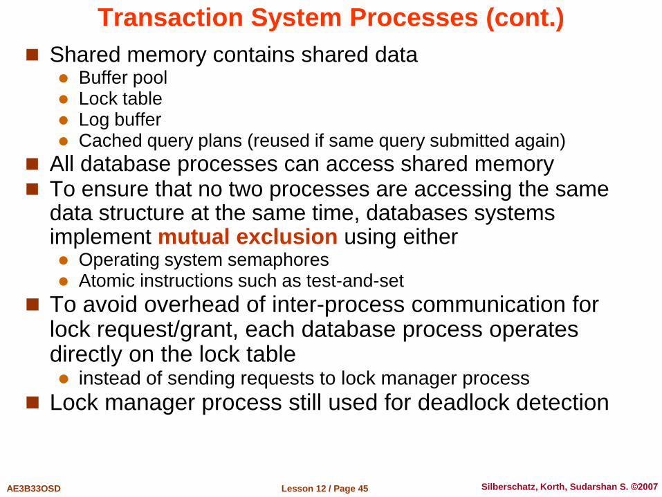
Transaction System Processes (cont.)
Shared memory contains shared data Buffer pool Lock table Log buffer Cached query plans (reused if same query submitted again)
All database processes can access shared memory To ensure that no two processes are accessing the same
data structure at the same time, databases systems implement mutual exclusion using either Operating system semaphores Atomic instructions such as test-and-set
To avoid overhead of inter-process communication for lock request/grant, each database process operates directly on the lock table instead of sending requests to lock manager process
Lock manager process still used for deadlock detection

Lesson 12 / Page 46 AE3B33OSD Silberschatz, Korth, Sudarshan S. ©2007
Parallel Systems
Parallel database systems consist of multiple processors and multiple disks connected by a fast interconnection network
A coarse-grain parallel machine consists of a small number of powerful processors
A massively parallel or fine grain parallel machine utilizes thousands of smaller processors
Two main performance measures: throughput – the number of tasks that can be completed in a given
time interval response time – the amount of time it takes to complete a single
task from the time it is submitted
Lesson 12 / Page 47 AE3B33OSD Silberschatz, Korth, Sudarshan S. ©2007
Parallel Database Architectures
Shared memory – processors share a common memory
Shared disk – processors share a common disk set
Shared nothing – processors share neither a common memory nor common disk
Hierarchical – hybrid of the above architectures

Lesson 12 / Page 48 AE3B33OSD Silberschatz, Korth, Sudarshan S. ©2007
Parallel Database Architectures
P
P
P
P
P
P
M
shared memory
PM
PM
PM
PM
PM
PM
shared disk
P M
PM
PM
PM
P M
shared nothing
P
P
P
P
P
P
MP
P
P
P
P
P
MP
P
P
P
P
P
M
hierarchical organization

Lesson 12 / Page 49 AE3B33OSD Silberschatz, Korth, Sudarshan S. ©2007
Shared Memory
Processors and disks have access to a common memory, typically via a bus or through an interconnection network.
Extremely efficient communication between processors – data in shared memory can be accessed by any processor without having to move it using software.
Downside – architecture is not scalable beyond about 32 processors since the bus or the interconnection network becomes a bottleneck
Widely used for lower degrees of parallelism (4 to 8).

Lesson 12 / Page 50 AE3B33OSD Silberschatz, Korth, Sudarshan S. ©2007
Shared Disk
All processors can directly access all disks via an interconnection network, but the processors have private memories. The memory bus is not a bottleneck
Architecture provides a degree of fault-tolerance – if a processor fails, the other processors can take over its tasks since the database is resident on disks that are accessible from all processors.
Examples: IBM Sysplex and DEC clusters (now part of Compaq) running Rdb (now Oracle Rdb) were early commercial users
Downside: bottleneck now occurs at interconnection to the disk subsystem.
Shared-disk systems can scale to a somewhat larger number of processors, but communication between processors is slower.
Lesson 12 / Page 51 AE3B33OSD Silberschatz, Korth, Sudarshan S. ©2007
Shared Nothing
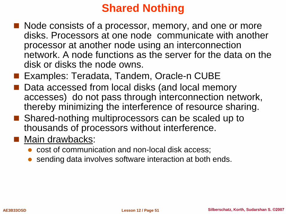
Node consists of a processor, memory, and one or more disks. Processors at one node communicate with another processor at another node using an interconnection network. A node functions as the server for the data on the disk or disks the node owns.
Examples: Teradata, Tandem, Oracle-n CUBE
Data accessed from local disks (and local memory accesses) do not pass through interconnection network, thereby minimizing the interference of resource sharing.
Shared-nothing multiprocessors can be scaled up to thousands of processors without interference.
Main drawbacks: cost of communication and non-local disk access;
sending data involves software interaction at both ends.

Lesson 12 / Page 52 AE3B33OSD Silberschatz, Korth, Sudarshan S. ©2007
Hierarchical Organization
Combines characteristics of shared-memory, shared-disk, and shared-nothing architectures.
Top level is a shared-nothing architecture nodes connected by an interconnection network, and do not share
disks or memory with each other.
Each node of the system could be a shared-memory system with a few processors.
Alternatively, each node could be a shared-disk system, and each of the systems sharing a set of disks could be a shared-memory system.
Reduce the complexity of programming such systems by distributed virtual-memory architectures Also called non-uniform memory architecture (NUMA)
Lesson 12 / Page 53 AE3B33OSD Silberschatz, Korth, Sudarshan S. ©2007
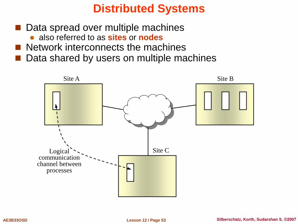
Distributed Systems
Data spread over multiple machines also referred to as sites or nodes
Network interconnects the machines Data shared by users on multiple machines
Site A Site B
Site C Logical communication channel between
processes

Lesson 12 / Page 54 AE3B33OSD Silberschatz, Korth, Sudarshan S. ©2007
Distributed Databases
Homogeneous distributed databases Same software & schema on all sites, data may be partitioned
among sites Goal: provide a feeling of a single database, hiding details of
distribution
Heterogeneous distributed databases Different software/schema on different sites Goal: integrate existing databases to provide useful functionality
Differentiate between local and global transactions A local transaction accesses data in the single site at which the
transaction was initiated. A global transaction either accesses data in a site different from the
one at which the transaction was initiated or accesses data in several different sites.
Lesson 12 / Page 55 AE3B33OSD Silberschatz, Korth, Sudarshan S. ©2007
Trade-offs in Distributed Systems
Sharing data – users at one site able to access the data residing at some other sites.
Autonomy – each site is able to retain a degree of control over data stored locally.
Higher system availability through redundancy – data can be replicated at remote sites, and system can function even if a site fails.
Disadvantage: added complexity required to ensure proper coordination among sites Software development cost. Greater potential for bugs. Increased processing overhead.
Lesson 12 / Page 56 AE3B33OSD Silberschatz, Korth, Sudarshan S. ©2007
Implementation Issues for Distributed Databases
Atomicity needed even for transactions that update data at multiple sites
The two-phase commit protocol (2PC) is used to ensure atomicity Basic idea: each site executes transaction until just before
commit, and the leaves final decision to a coordinator
Each site must follow decision of coordinator, even if there is a failure while waiting for coordinators decision
2PC is not always appropriate: other transaction models based on persistent messaging, and workflows, are also used
Distributed concurrency control (and deadlock detection) required
Data items may be replicated to improve data availability

End of Lesson 12
&
the Entire Course
Questions?