lesson 8 332a - siu
TRANSCRIPT

6/17/2015
1
ET 332a
Dc Motors, Generators and Energy Conversion Devices
1
Learning ObjectivesLearning Objectives
After this presentation you will be able to:
Compute the average output voltage of a dc generator given machine physical construction parameters.
Draw the schematic circuit model of a dc machine Find generator output voltage using a
magnetization curve and defining formulas. Compute generator voltage regulation.
2

6/17/2015
2
Average Induced Voltage in a
Generator
3
Where v = velocity of conductor
For rotating system
v = angular velocity dθ/dt = ω rad/s
Start with fundamental equation
)sin(vlBe θ⋅⋅⋅=
Frequency of e related to number of field poles and rotational speed by:
Angular velocity relates to frequency f (cycles/s or Hertz) by: ω = 2πf
120
nPf
⋅= Where: P = number of field poles
n = rotational speed (rpm)
4
Average Induced Voltage in a Generator
Substituting into fundamental equation and simplifying gives:
30
NPnE
pa
a
Φ⋅⋅⋅=
Where: P = number of polesn = rotational speedNa = # of turns in coilΦp = field fluxEa = average induced
voltage
Consider machine construction details and define another voltage formula

6/17/2015
3
5
Average Induced Voltage in a Generator
Define the number of conductors in field in terms of windings
2
zN aa =
za = Total number of armature conductors in the field.
Substitute into previous equation to get:
a60
zPnE
pa
a ⋅
Φ⋅⋅⋅=
Where:a = number of parallel paths
6
Average Induced Voltage in a Generator
The number of poles, parallel paths, and conductors are constant once the machine is constructed so define:
a60
zPk aG ⋅
⋅=
The constant kG also known as ke in some texts. Relates motor voltage to speed and field flux.
Where kG = emf constant
pepGa nknkE Φ⋅⋅=Φ⋅⋅=
Note : Ea is proportional to the flux and to the rotational speed. If conditions of machine are know at one n and Φp, another operating point can be found by equating ratios.

6/17/2015
4
Induced Voltage Examples
7
Example 1: A 2 pole dc motor armature rotates at 1800 rpm. It has 400 turns in the armature winding. The magnetic field flux is 0.0025 Wb. Compute the average induced voltage.
Example 2: A 4 pole dc machine rotates at 200 rad/s in a magnetic field of 0.0048 Wb. There are 4 parallel current paths that have 200 conductors. Find the induced voltage in the armature and the emf constant for the machine.
Convert ω τo n for formularpm 1910.8rad/s 200
2
60n =⋅
π
=
( )( )( )( )( )
Vdc 57.30460
Wb0048.02004rpm 8.1910
a60
zPnE
pa
a ==⋅
Φ⋅⋅⋅=
8
Induced Voltage ExamplesExample 2 Continued: Find the emf constant
Lump the constants and compute
( )( )( )
rpm-V/Wb 333.3460
2004
a60
zPk ae ==
⋅⋅
=
Example 3: A 4 pole 50 kW dc machine has a value of Ea = 110 V at 1100 rpm. What is the induced voltage if the speed is increased 20%?
No change in flux
Find Ea2 Ans

6/17/2015
5
9
Induced Voltage ExamplesExample 4: A 4 pole dc machine has a value of Ea = 50 V at 400 rpm. What is the value of Ea if the pole flux is doubled while the speed remains constant?
Assumes no saturation
Ans
10
Circuit Model of Dc Machines
Racir = dc resistance of the armature windings , interpoles, etcLa = inductance of armature circuitRf = dc resistance of the field windingsLf = inductance of the field windings
Ea = internally induced voltageVt = terminal voltage of machineVf = field electromagnetic source voltage
Vf
+
Ea
+ Vt
+
Lf
La
Rf
Racir Inductances have no effect when the values of dc current are not changing. Shown to indicate coils.

6/17/2015
6
Generator Circuit Model
11
Ea
+Lf
La
Rf
Racir
Vf
Ia
Vt
+
Generator model - mechanical power converted to electric power. Ia leaves the + terminal of armature
If
Field current produces field flux
From KVL around armature circuit
taciraa VRIE +⋅=
Total resistance of armature circuit Racir
CWIPaacir RRRR ++=
Where:Ra = armature resistanceRIP = interpole winding resistanceRcw = compensation winding resistance
Brush losses P=2 ·Ia1 volt drop for each brush
Brushdrop
12
Motor Circuit Model
Ea
+Lf
La
Rf
Racir
Vf
Ia
If
Brushdrop
Vt
+
Motor model - electric power converted tomechanical power. Ia enters the + terminal ofarmature
Analyze the field circuit
f
ff
R
VI =
R
fp
IN ⋅=Φ
Control If with field rheostat
Rc
Vf
Lf
Rf
If
Rc = field coil resistanceRf = field rheostat resistance
cf
ff
RR
VI
+=

6/17/2015
7
Separately Excited Dc Generator
13
Racir La
Ea
Lf
Rc
Rf
Vf
Vt
N
n
Separate source of supply develops field flux. Source called the exciter
RL
cf
ff
RR
VI
+=Model Equations: Field circuit current
Magnetic coupling to induced average voltage
R
Gfa
knINE
⋅⋅⋅=
pGa nkE Φ⋅⋅=Ea in terms of flux forconstant If
nkE ea ⋅=
Φp
Ea proportional to n for constant IfpGe kk Φ⋅=
If
14
Separately Excited Dc Generator
pGa nkE Φ⋅⋅=
Generally flux, Φ is non-linear with respect to the field current If.
Magnetizing curve for generator givesrelationship for Ea as a function of field current.
0 1 2 3 4 5 6 7 8 9 10 11 12 13 140
20
40
60
80
100
120
140
160
180
200
220
240
260
280
300
320
340
360
380
400
Field Current (A)
Induced EMF (V)
E ai
I fi
If If is in linear part of curve Ea is proportional to n and If.
Field Current, If (A)
Ind
uce
d E
MF,
Ea(
V)
ke valid here
Generator Magnetizing Curve

6/17/2015
8
Terminal Voltage Regulation
15
Voltage regulation finds the percent change in terminal voltage from no-load to full load
Vt
KVL around armature circuitwith switch closed
taciraa VRIE +⋅=
Ia
n
With switch closed and n constant Vt < Ea and decreases as Ia increases
Ia= 0 with switch open so:ta
tacira
VE
VRE
=
+⋅= 0No-load voltage = Ea
16
Terminal Voltage Regulation
rated
ratednl
V
VVVR%
−=
For rated terminal voltage
Where: %VR = percent voltage regulationVnl = no-load terminal voltageV rated = name plate rating of the terminal voltage
when generator delivers rated power.
How does terminal voltage change with delivered power?
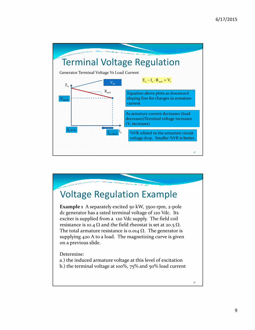
6/17/2015
9
17
Terminal Voltage Regulation
Ia
Ea
Ia, rated
Vrated
Vnltaciraa VRIE =⋅−
Racir
Generator Terminal Voltage Vs Load Current
Equation above plots as downwardsloping line for changes in armature current
Ia = 0
As armature current decreases (load decreases)Terminal voltage increases (Vt increases)
%VR related to the armature circuit voltage drop. Smaller %VR is better.
Voltage Regulation Example
18
Example 1 A separately excited 50 kW, 3500 rpm, 2-pole dc generator has a rated terminal voltage of 120 Vdc. Its exciter is supplied from a 120 Vdc supply. The field coil resistance is 10.4 Ω and the field rheostat is set at 20.5 Ω. The total armature resistance is 0.014 Ω. The generator is supplying 420 A to a load. The magnetizing curve is given on a previous slide.
Determine:a.) the induced armature voltage at this level of excitationb.) the terminal voltage at 100%, 75% and 50% load current
6/17/2015
10
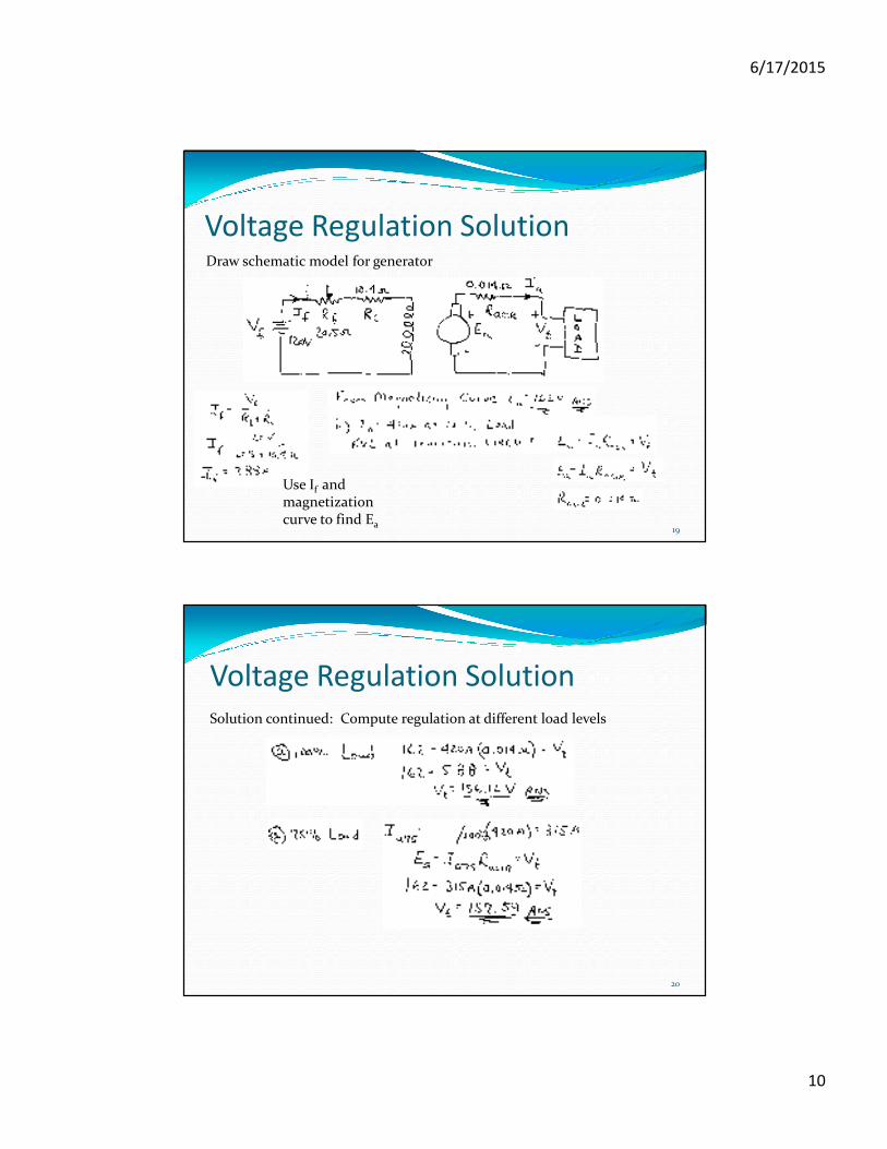
Voltage Regulation Solution
19
Draw schematic model for generator
Use If and magnetization curve to find Ea
20
Voltage Regulation Solution
Solution continued: Compute regulation at different load levels

6/17/2015
11
21
Voltage Regulation Solution
Solution continued: Compute regulation at different load levels
Summary of calculations
% Load Ia Vt
100 420 A 156.12
75 315 A 157.59 V
50 210 A 159.86 V
Terminal voltage increases on generator as the load current decreases
22
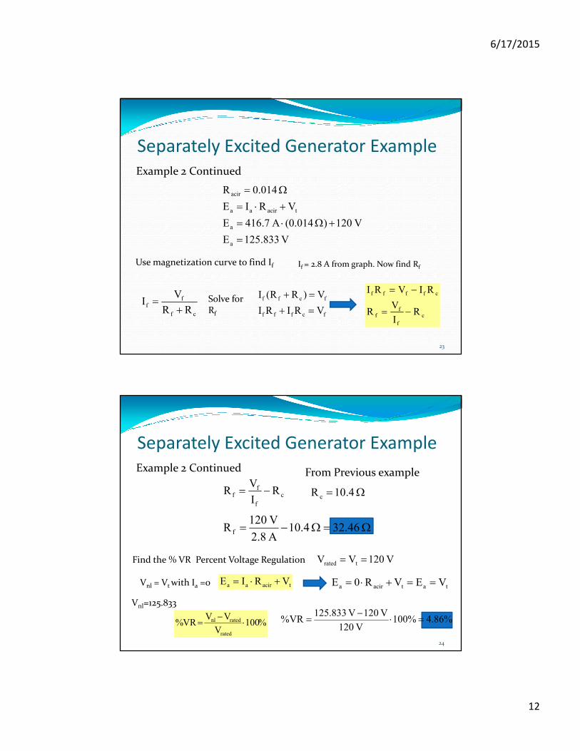
Example 2: For the machine in Example 1, ,determine the field rheostat setting for the machine to deliver rated output current at rated voltage. Also determine the %VR at rated load.
Separately Excited Generator Example
Solution
Calculate the current at rated load for the generator power rating
dc V 120VV
W50,000kW 50P
t rated
rated
==
== Find Rated I from power and voltage
A 7.416V 120
W000,50
V
PI
t
ratedrateda, ===
Now find value of Ea with Vt = 120 V using taciraa VRIE +⋅=
6/17/2015
12
23
Separately Excited Generator Example
Example 2 Continued
V 833.125E
V 120) (0.014A 7.416E
VRIE
014.0R
a
a
taciraa
acir
=
+Ω⋅=
+⋅=
Ω=
Use magnetization curve to find If If = 2.8 A from graph. Now find Rf
cf
ff
RR
VI
+= Solve for
Rf fcfff
fcff
VRIRI
V)RR(I
=+
=+
c
f
ff
cffff
RI
VR
RIVRI
−=
−=
24
Separately Excited Generator Example
Example 2 Continued
c
f
ff R
I
VR −= Ω= 4.10R c
Ω=Ω−= 32.46 4.10A 2.8
V 120R f
From Previous example
Find the % VR Percent Voltage Regulation V 120VV trated ==
Vnl = Vt with Ia =0 taciraa VRIE +⋅=tatacira VEVR0E ==+⋅=
Vnl=125.833
%100V
VVVR%
rated
ratednl ⋅−
= %86.4%100V 120
V 120V 833.125VR% =⋅
−=

6/17/2015
13
ET 332a
Dc Motors, Generators and Energy Conversion Devices
25