lesson 6. energy storage - educypediaeducypedia.karadimov.info/library/lesson6.pdf · energy...
TRANSCRIPT

Energy Technology A. Y. 2006-07
1
LESSON 6.ENERGY STORAGE
Energy Technology A. Y. 2006-07
2
Contents (I)• Introduction.• Choosing an energy storage method.• Classification of energy storage methods.• Mechanical energy storage methods.
– Pumped hydro storage.– Compressed air.– Flywheels.
• Chemical and electrochemical storage.– Hydrogen.– Batteries.

Energy Technology A. Y. 2006-07
3
Contents (II)• Chemical and electrochemical storage.
– Hybrid electric vehicles.– Reaction enthalpies.
• Thermal storage methods.– Sensible heat.– Latent heat.
• Electric and magnetic storage.– Capacitors.– Magnetic fields.
• Bibliography.
Energy Technology A. Y. 2006-07
4
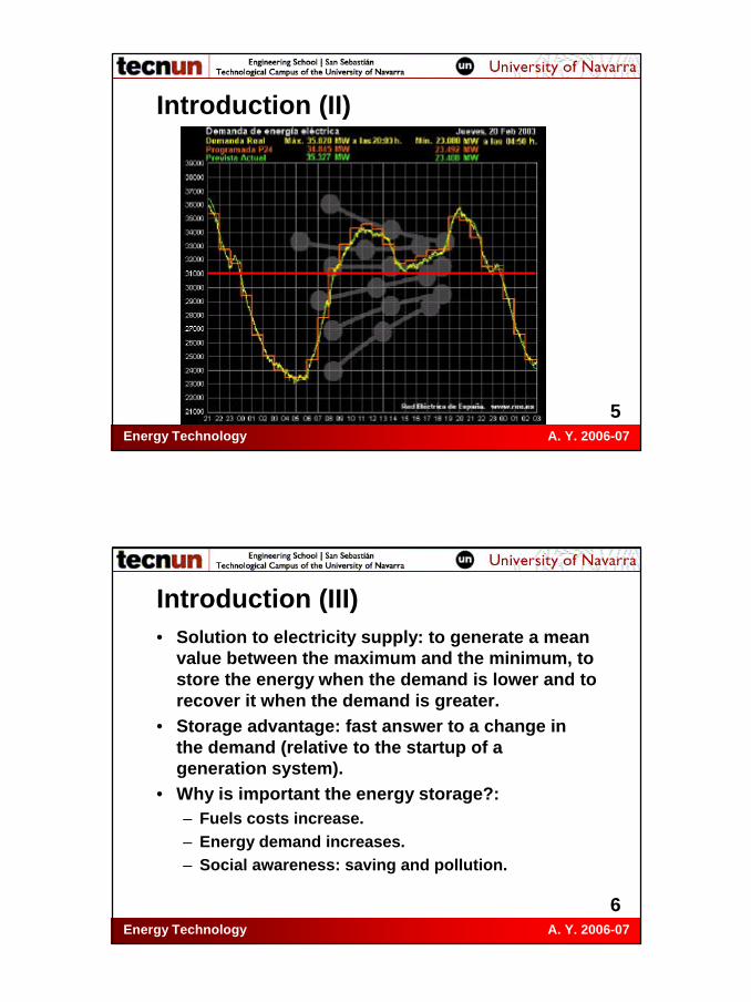
Introduction (I)• Main problem of an Energy System: to match
supply and demand of energy.• Transport sector: energy demand is variable
over time ⇒ engine (M.A.C.I.) ⇒ no storage, the clutch is used to produce or not toproduce movement (energy losses).
• Electricity supply: the demand varies alongthe day ⇒ power plants not adaptable.
• Electricity: principal application of energystorage.
Energy Technology A. Y. 2006-07
5
Introduction (II)
Energy Technology A. Y. 2006-07
6
Introduction (III)• Solution to electricity supply: to generate a mean
value between the maximum and the minimum, tostore the energy when the demand is lower and torecover it when the demand is greater.
• Storage advantage: fast answer to a change in the demand (relative to the startup of a generation system).
• Why is important the energy storage?:– Fuels costs increase.– Energy demand increases.– Social awareness: saving and pollution.

Energy Technology A. Y. 2006-07
7
Introduction (IV)• Large scale energy storage systems: electricity
power plants and large factories.• Medium and small scale: solar and wind power
plants. Variability of the supply due to weatherchanges.
• The energy storage system means a saving in initial investment (the power system works at a lower level of load) and in fuel. The energystorage system cost must be recouped.
• Disadvantage: energy storage density (J/kg orJ/m3) less than fossil fuels.
• Oil: 40 MJ/kg; coal: 29 MJ/kg; natural gas: 50 MJ/kg.
Energy Technology A. Y. 2006-07
8
Choosing the method (I)• Storage methods work by applying a
transformation to spare energy and applyingthe reverse transformation to recover it.
• The most important parameter is theefficiency of the transformations.
• Economic parameters:– Cost per kW of the transforming systems (to
store and to recover the energy).– Cost per kW of the storage system.

Energy Technology A. Y. 2006-07
9
Choosing the method (II)• Energy Parameters:
– Efficiency of the storage transformation.– Storage capacity of the system:
• Energy density.• Supply time to a steady load.
– Efficiency of the recovering transformation.– System useful life: number of storage/recovering
cycles.– System use function: storing system
output/production system output (relative tostorage capacity).
Energy Technology A. Y. 2006-07
10
Choosing the method (III)• Safety: storage system and transformation
systems designed to be non-destructive tolife and property.
• The choice must be a compromise betweenthe method with the highest storage capacityand the one which is most economicallyfavourable.

Energy Technology A. Y. 2006-07
11
Choosing the method (IV)• Ideal storage system equation:
• Es is the energy in the storage system.• is the input power.• is the output power demanded by the
user.• are the energy losses. Function of:
– System state properties (temperature, speed,…).
– Time.
)()()( tQtWtWdt
dEoutin
s &&& −−=
)(tWin&
)(tWout&
)(tQ&
Energy Technology A. Y. 2006-07
12
Choosing the method (V)• Storage system performance condition:
– The power input must be such as to make up for losses, to ensure that over a cycle time, tmax, the change in stored energy is zero:
• Storage efficiency:
( )∫∫∫ −=⇒= maxmaxmax tin
tout
t s dttQtWdttWdtdt
dE000
)()()(0 &&&
∫∫==
max
max
tin
tout
in
outs
dttW
dttW
EE
0
0
)(
)(
&
&η
Energy Technology A. Y. 2006-07
13
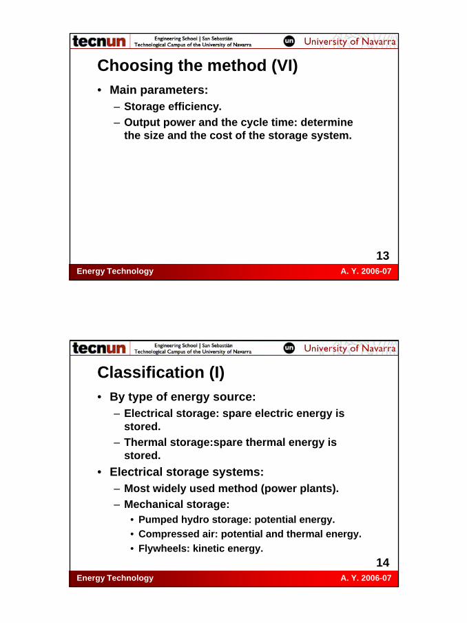
Choosing the method (VI)• Main parameters:
– Storage efficiency.– Output power and the cycle time: determine
the size and the cost of the storage system.
Energy Technology A. Y. 2006-07
14
Classification (I)• By type of energy source:
– Electrical storage: spare electric energy is stored.
– Thermal storage:spare thermal energy is stored.
• Electrical storage systems:– Most widely used method (power plants).– Mechanical storage:
• Pumped hydro storage: potential energy.• Compressed air: potential and thermal energy.• Flywheels: kinetic energy.

Energy Technology A. Y. 2006-07
15
Classification (II)• Electrical storage systems:
– Chemical and electrochemical storage:• Hydrogen.• Batteries.
– Electrical and electromagnetic storage:• Capacitors and ultracapacitors.• Magnetic fields and superconductor rings.
Energy Technology A. Y. 2006-07
16
Classification (III)• Comparing some electrical storage systems:
System Power Density (kW/kg)
Energy Density (Wh/kg - MJ/kg)
Mean life (No. of cycles)
Compressed air 10 180 - 0.65 10,000,000
Lead-acid battery 0.2 50 - 0.18 1,000
Nickel-cadmium battery 0.2 50 - 0.18 2,000
Steel flywheel 10 55 - 0.20 100,000
Fused silica flywheel - 870 - 3.13 100,000
Energy Technology A. Y. 2006-07
17
Classification (IV)• Thermal storage systems:
– Thermal storage:• Sensible heat.• Latent heat.
– Chemical storage:• Reversible endothermic reactions enthalpy.
Energy Technology A. Y. 2006-07
18
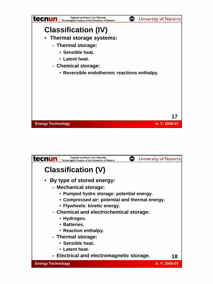
Classification (V)• By type of stored energy:
– Mechanical storage:• Pumped hydro storage: potential energy.• Compressed air: potential and thermal energy.• Flywheels: kinetic energy.
– Chemical and electrochemical storage:• Hydrogen.• Batteries.• Reaction enthalpy.
– Thermal storage:• Sensible heat.• Latent heat.
– Electrical and electromagnetic storage.
Energy Technology A. Y. 2006-07
19
Classification (VI)
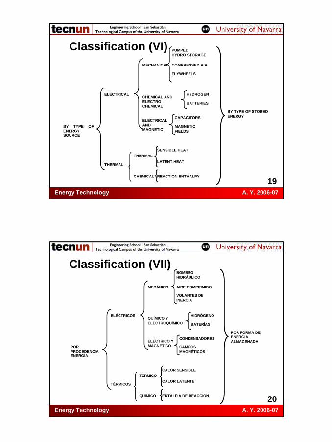
HYDROGEN
BATTERIES
BY TYPE OF ENERGY SOURCE
ELECTRICAL CHEMICAL AND ELECTRO-CHEMICAL
MECHANICAL
ELECTRICAL AND MAGNETIC
COMPRESSED AIR
PUMPED HYDRO STORAGE
FLYWHEELS
MAGNETIC FIELDS
CAPACITORS
THERMAL
CHEMICAL
THERMAL LATENT HEAT
SENSIBLE HEAT
REACTION ENTHALPY
BY TYPE OF STORED ENERGY
Energy Technology A. Y. 2006-07
20
Classification (VII)
HIDRÓGENO
BATERÍAS
POR PROCEDENCIA ENERGÍA
ELÉCTRICOS QUÍMICO Y ELECTROQUÍMICO
MECÁNICO
ELÉCTRICO Y MAGNÉTICO
AIRE COMPRIMIDO
BOMBEO HIDRÁULICO
VOLANTES DE INERCIA
CAMPOS MAGNÉTICOS
CONDENSADORES
TÉRMICOS
QUÍMICO
TÉRMICO CALOR LATENTE
CALOR SENSIBLE
ENTALPÍA DE REACCIÓN
POR FORMA DE ENERGÍA ALMACENADA

Energy Technology A. Y. 2006-07
21
Pumped hydro storage (I)• Most highly developed and widely used method.• Storage of a mass of water in form of
gravitational potential energy.• Example: 1,000 kg (= 1 m3) raised to 100 m ⇒ E =
m·g·z = 9.8·105 J ≈ 1 MJ = 0,2725 kWh.• It is neccesary to store great amounts of water at
large height.• Appropriate topography: two big reservoirs, big
height difference and small horizontal distance.• Elevated reservoir (dam) or natural underground
cavity.
Energy Technology A. Y. 2006-07
22
Pumped hydro storage (II)

Energy Technology A. Y. 2006-07
23
Pumped hydro storage (III)• Two types:
– Pure pumping power plant: diversion between two reservoirs or dams without supply of outside water (only for leakages).
– Mixed power plant with pumping: water provided by river in upper dam (hydroelectric power plant).
• They work with reversible pump-turbine.• Losses: pump and turbine efficiencies, piping
head losses, leakages and evaporation.
Energy Technology A. Y. 2006-07
24
Pumped hydro storage (IV)

Energy Technology A. Y. 2006-07
25
Pumped hydro storage (V)• Global efficiency: ≈ 65-75%.• Stored energy: between 200 and 2.000 MWh.• Main Spanish pumping power stations:
(*) Pure pumping power plant
Power plant River Province Power (MW) Villarino Tormes Salamanca 810
La Muela (*) Júcar Valencia 628 Estany-Gento-Saliente (*) Flamisell Lérida 451
Aldeadávila II Duero Salamanca 421 Tajo de la Encantada (*) Guadalhorce Málaga 360
Aguayo (*) Torina Cantabria 339 Conso Camba-Conso Orense 228
Valdecañas Tajo Cáceres 225 TOTAL 5.120
Energy Technology A. Y. 2006-07
26
Pumped hydro storage (VI)
Energy Technology A. Y. 2006-07
27
Pumped hydro storage (VII)
Energy Technology A. Y. 2006-07
28
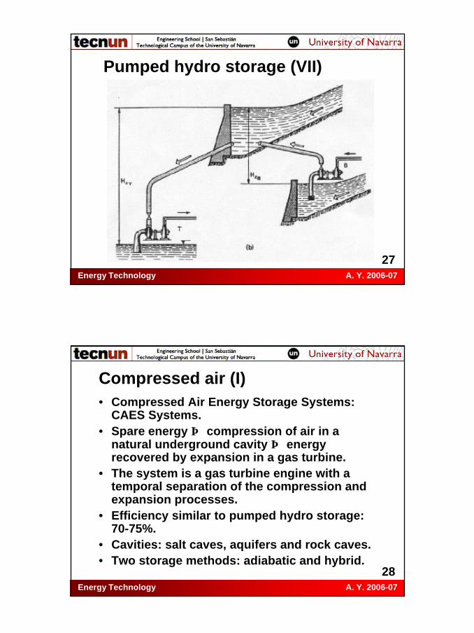
Compressed air (I)• Compressed Air Energy Storage Systems:
CAES Systems.• Spare energy ⇒ compression of air in a
natural underground cavity ⇒ energy recovered by expansion in a gas turbine.
• The system is a gas turbine engine with a temporal separation of the compression and expansion processes.
• Efficiency similar to pumped hydro storage: 70-75%.
• Cavities: salt caves, aquifers and rock caves.• Two storage methods: adiabatic and hybrid.

Energy Technology A. Y. 2006-07
29
Compressed air (II)
Energy Technology A. Y. 2006-07
30
Compressed air (III)• Adiabatic method:
– The energy of the heating during the compression is stored in the air or in an auxiliary system and it is returned before the expansion.
– Advantage: For the same pressure ratio, the work of the turbine is proportional to the input temperature.
• Hybrid method:– The compression heat is “removed” to the
environment and heat is added by combustion before the expansion.
– Additional costs of operation and maintenance.
Energy Technology A. Y. 2006-07
31
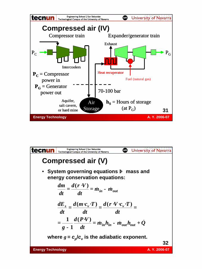
Compressed air (IV)Compressor train Expander/generator train
IntercoolersHeat recuperator
PC PG
Exhaust
AirStorage
Aquifer,salt cavern,
or hard mine
hS = Hours of storage(at PG)
PC = Compressorpower in
PG = Generatorpower out 70-100 bar
Compressor train Expander/generator train
IntercoolersHeat recuperator
PC PG
Exhaust
AirStorage
Aquifer,salt cavern,
or hard mine
hS = Hours of storage(at PG)
PC = Compressorpower in
PG = Generatorpower out 70-100 bar
Fuel (natural gas)
Energy Technology A. Y. 2006-07
32
Compressed air (V)• System governing equations ⇒ mass and
energy conservation equations:
where γ = cp/cv is the adiabatic exponent.
outin mmdt
Vddtdm
&& −==)·(ρ
Qhmhmdt
VPddt
TcVddt
Tcmddt
dE
outoutinin
vvs
&&& +−=−
=
===
)·(1
1
)···()··(
γ
ρ

Energy Technology A. Y. 2006-07
33
Compressed air (VI)• Work in the compressor:
• Heat in the combustor:
• Work in the turbine:
• Net efficiency:
( )[ ]c
pinpinc
PPTcmTTcmW
ηγγ
γγ 1121
121
1)(
−−−
=−=&
&&
comb
poutf
TTcmQ
η)( 34 −
=&&
( )[ ]γγηγ
γ 1344 1
1−−
−= PPTcmW pouttt &&
fc
ttotal QW
W+
=η
Energy Technology A. Y. 2006-07
34
Compressed air (VII)• The storage volume depends on pressure for
the same storage capacity ⇒ we are interested in high storage pressures to reduce volume and costs.
• Problems using the adiabatic method in salt caves: at P = 100 bar ⇒ T = 800 ºC ⇒ salt melts ⇒ auxiliary system to store the heat.

Energy Technology A. Y. 2006-07
35
Compressed air (VIII)• CAES plants examples:
– Huntorf, Germany (1978):
Energy Technology A. Y. 2006-07
36
Compressed air (IX)• CAES plants examples:
– Huntorf, Germany (1978):

Energy Technology A. Y. 2006-07
37
Compressed air (X)• CAES plants examples:
– McIntosh, Alabama (1991):• Power = 100 MW.• Cavern: Top of solution-mined salt cavern is
1,500 feet (457 m) underground and bottom of cavern is 2,500 feet (762 m) underground.
• The diameter of the cavern is 220 feet (67 m) and the volume is 10 million of cubic feet (283,000 m3).
• At full charge, air pressure is 1,100 pounds per square inch (75.8 bar). At full discharge, cavern air pressure is 650 pounds per square inch (44.8 bar).
Energy Technology A. Y. 2006-07
38
Compressed air (XI)• CAES plants examples:
– McIntosh, Alabama (1991):• Capacity: Compressed air flows through the
CAES plant generator at a rate of 340 pounds of air per second (154 kg/s).
• The fuel consumption during generation is equal to 4,600 Btu (1,35 kWh) (HHV) per kilowatt-hour (kWh) of electricity. There are about 20,750 Btu in each gallon of gasoline.
• The electricity consumed during compression is 0.82 kWh of peak load generation.

Energy Technology A. Y. 2006-07
39
Compressed air (XII)
Energy Technology A. Y. 2006-07
40
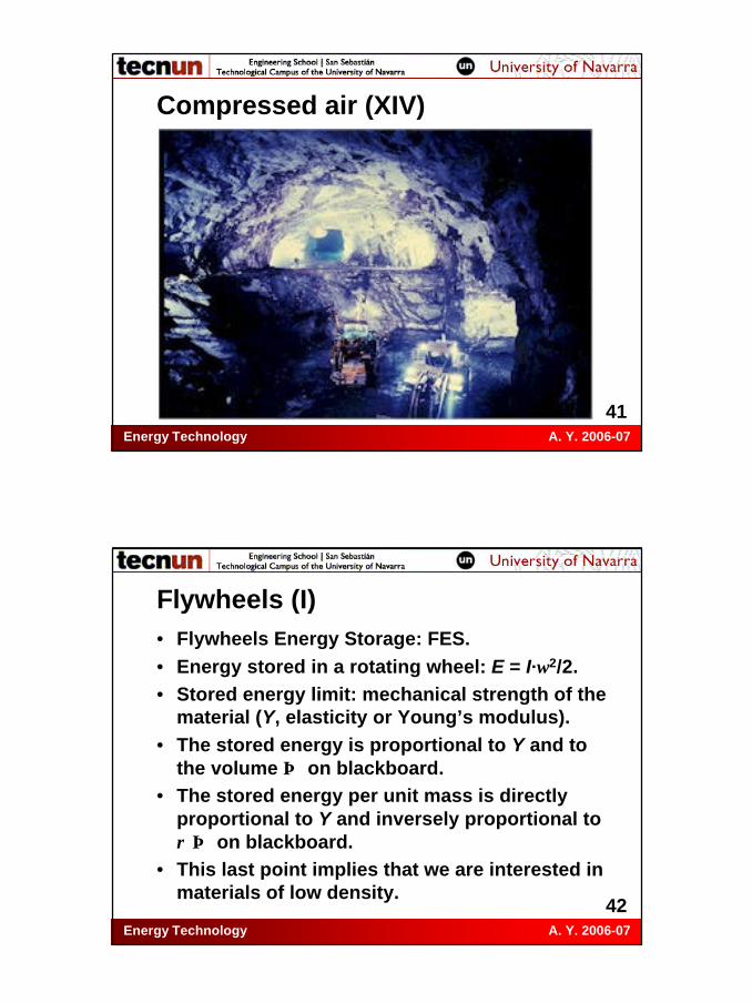
Compressed air (XIII)• CAES plants examples:
– Norton, Ohio (under development):• A 2,200-foot-deep limestone (cal) mine.• Working pressures: 800-1,600 psi (55-110 bar).• The power plant will be built in units brought on
line in increments of 300 megawatts as units are completed. Ultimately up to about 2,700 megawatts will be built, which will be enough generating capacity for about one million homes.
Energy Technology A. Y. 2006-07
41
Compressed air (XIV)
Energy Technology A. Y. 2006-07
42
Flywheels (I)• Flywheels Energy Storage: FES.• Energy stored in a rotating wheel: E = I·ω2/2.• Stored energy limit: mechanical strength of the
material (Y, elasticity or Young’s modulus).• The stored energy is proportional to Y and to
the volume ⇒ on blackboard.• The stored energy per unit mass is directly
proportional to Y and inversely proportional to ρ ⇒ on blackboard.
• This last point implies that we are interested in materials of low density.

Energy Technology A. Y. 2006-07
43
Flywheels (II)• The stored energy per unit mass is directly
proportional to (explained on blackboard):– The ratio RG/Rmax ⇒ thin annular ring ⇒ low
energy stored per unit volume.– The tip speed of the outermost element, VT ⇒
limited by the force balance between the centrifugal force and the stress of the material.
– The geometric parameter, Ks.– The speed asociated with the material
properties, am.
Energy Technology A. Y. 2006-07
44
Flywheels (III)• Values of the geometric parameter for
different flywheels designs:
Energy Technology A. Y. 2006-07
45
Flywheels (IV)• Properties of flywheel materials:
Material Density (kg/m3)
Emax (Wh/kg)
am (m/s)
Aluminium 2,700 20 190 Treated steel 8,000 55 280 E-glass fiber 2,500 190 570 Carbon fiber 1,800 200 600 S-glass fiber 2,500 240 660 Fused silica 2,100 870 1,200
Energy Technology A. Y. 2006-07
46
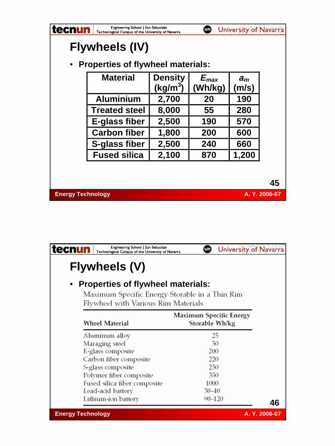
Flywheels (V)• Properties of flywheel materials:

Energy Technology A. Y. 2006-07
47
Flywheels (VI)• Properties of flywheel materials:
– Steels: very dense, small stress, danger if breakage (fragments dispersed).
– Fiber materials:• Disadvantages: very expensive and low
availability.• Advantages: anisotropy of properties and no
danger if breakage (dust).
• Reference values: D = 4.75 m and m = 100 -200 t ⇒ E = 10 MWh at 3.500 rpm with Power = 3 MW and η = 90%.
Energy Technology A. Y. 2006-07
48
Flywheels (VII)• Whole system:
– Housing for protection and sealing up: to avoid danger in case of breakage.
– Mechanical or magnetic bearings: to reduce the transmision and the friction losses.
– Vacuum pump: to eliminate the aerodynamic losses.

Energy Technology A. Y. 2006-07
49
Flywheels (VIII)
Energy Technology A. Y. 2006-07
50
Flywheels (IX)

Energy Technology A. Y. 2006-07
51
Flywheels (X)
Energy Technology A. Y. 2006-07
52
Flywheels (XI)

Energy Technology A. Y. 2006-07
53
Flywheels (XII)
Energy Technology A. Y. 2006-07
54
Hydrogen (I)• Chemical storage methods: Production of
chemical compounds by means of electrical or thermal spare energy for later conversion in electrical energy.
• Hydrogen advantages:– Compatible with any type of primary energy.– Unlimited quantities (water) and cyclic use.– Not pollutant. Combustion products: H2O and
traces of NOx.

Energy Technology A. Y. 2006-07
55
Hydrogen (II)• Production methods: Thermochemical and
Electrochemical.• Thermochemical production method:
– Fossil fuels reforming.– Efficiencies: 65-75%.– High temperatures are required.– Pollution: CO2, NOx, incomplete reactions.– It requires water and heat.
Energy Technology A. Y. 2006-07
56
Hydrogen (III)• Thermochemical production method:
– Types of reforming processes:• Steam reforming: Hydrogen production from
natural gas reacting with steam over a nickel catalyst at high temperature (840-950 ºC) and high pressure (20-30 bar). Endothermic.
• Partial oxidation reforming: At high temperature (1,200-1,500 ºC) and high pressure (20-90 bar). With oxygen and steam. Used for oil and coal. Exothermic.
• Autothermal reforming: Combination of the two previous processes.
• Thermal decomposition reforming: heat + hydrocarbon → coal + hydrogen.
Energy Technology A. Y. 2006-07
57
Hydrogen (IV)• Electrochemical production method:
– Electrolysis: water decomposition by passing an electric current through it.
– Low pressure electrolyser: temperature = 70-90 ºC; voltage = 1.85-2.25 V; electricity consumption = 4.5 kWh/m3; hydrogen purity > 99.8%.
– Efficiency > 50%, but it is expensive due to the high energy consumption and to the cost of the equipment.
Energy Technology A. Y. 2006-07
58
Hydrogen (V)• Electrochemical production method:
– Only 4% of hydrogen produced by electrolysis.– Electrolysis can be suitable when coupled with
a renewable energy source. – Components of an electrolyser:
• Electrolyte: conductor saline solution. Normally potassium hydroxide (KOH).
• Electrodes: nickel or low-carbon nickeled steel.• Porous membrane: to avoid mixture of oxygen
and hydrogen (ions).

Energy Technology A. Y. 2006-07
59
Hydrogen (VI)• Electrochemical production method:
– Anode reaction (oxidation):2 H2O (l) → O2 (g) + 4 H+ (sol) + 4e-.4 OH- (sol) → O2 (g) + 2 H2O (l) + 4e-.
– Catode reaction (reduction):4 H2O (l) + 4 e- → 2 H2 (g) + 4 OH- (sol).4 H+ (sol) + 4 e- → 2 H2 (g).
– Global reaction:2 H2O (l) → 2 H2 (g) + O2 (g).
Energy Technology A. Y. 2006-07
60
Hydrogen (VII)• Other production methods (under
development):– Water photolysis: use of photosensible
substances to split water directly from solar light (like in photosynthesis).
– Photobiological: using organisms (algae and bacteria) that produce hydrogen in their metabolic processes.
– Biomass gasification.

Energy Technology A. Y. 2006-07
61
Hydrogen (VIII)• Hydrogen storage:
– Low volumetric energy density ⇒ bigger storage tank.
– Higher mass energy density (140 MJ/kg). Unbalanced by the weight of the storage tanks.
– Great scale storage: like compressed air in salt caves, aquifers, rock caves or artificial caves.
– Low scale storage: compressed (gas), liquid or metal hydride.
Energy Technology A. Y. 2006-07
62
Hydrogen (IX)• Compressed hydrogen storage:
– Energy required to compress the gas.– Weight of the tank.– Most widely used method.
• Liquid hydrogen storage:– Cryogenic tanks (-253 ºC).– Liquefying process requires energy.– Under development.

Energy Technology A. Y. 2006-07
63
Hydrogen (X)
Energy Technology A. Y. 2006-07
64
Hydrogen (XI)• Metal hydrides:
– Combination of metallic alloys that absorb hydrogen and release it through a reversible process, changing the conditions of pressure or temperature.
– Advantage: safety.– Disadvantages: low hydrogen absorption (2-
7% in weight), purity of hydrogen, weight of the metal and high costs.
– Under development.
Energy Technology A. Y. 2006-07
65
Hydrogen (XII)• Hydrogen energy extraction:
– Brayton cycle.– Gas turbine.– Fuel cells.
Energy Technology A. Y. 2006-07
66
Batteries (I)• Electrochemical storage batteries: electric energy
⇒ chemical energy.• Battery: two electrodes immersed in an
electrolyte where they exchange ions and connected to an external circuit to exchange electrons.
• The lead-acid batteries used in vehicles are not suitable for great scale energy storage due to its:– Low energy density per unit of weight and per unit
of volume.– High cost.– Small useful life (charge-discharge cycles).
• R+D to eliminate these disadvantages.
Energy Technology A. Y. 2006-07
67
Batteries (II)
Energy Technology A. Y. 2006-07
68
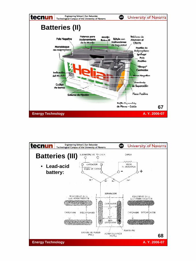
Batteries (III)• Lead-acid
battery:
+-
- +

Energy Technology A. Y. 2006-07
69
Batteries (IV)• Ni-Cd battery. Compared with lead-acid, they
have:– Half the weight.– Longer useful life.– More temperature tolerance.– Lower power density.– Greater cost.– Environmental problems with Cd.
Energy Technology A. Y. 2006-07
70
Batteries (V)• Nickel-Metal Hydride battery:
– Anode of metal hydride– Improvement in energy and power density.– High self-discharge rate.– Expensive.
• Ag-Zn battery: high storage density, but small useful life (30-300 cycles).
• Na-S battery: high storage density and long useful life, but it works at 300 ºC and has problems of leakage.

Energy Technology A. Y. 2006-07
71
Batteries (VI)• Lithium-ion battery:
– Three times energy density of lead-acid.– More expensive.
• Lithium-polymer battery: with solid polymer electrolyte.
• Li-Cl and Li-Te batteries: similar to Na-S.• Zn-Cl battery: it supplies a constant power
during discharge.• Zinc-air batteries: it absorbs oxygen from the
air during discharge.
Energy Technology A. Y. 2006-07
72
Batteries (VII)Type of battery
Pb-acid
Ni-Cd Ni-metal hydride
Na-S Li-ion
Li-poly
Zn-Cl
Zn-air
Li-FeS2
Vmax (V) 2.5 1.35 - 2.75 - - 2.12 - 2.4 Vmin (V) 1.75 - - 1.83 - - 1.98 - 1 T (ºC) 25 25 25 300-
350 25 50-70
30-50 - 400-
450 ηe 70-80 - - 85 - - 70 - 70
Life (No. of cycles)
1,500-2,000
1,500-3,000
1,000-2,000
1,000-2,000
500-1,000
500-1,000
500-1,000
200-300
200-1,000
Energy density (Wh/kg)
150-200 200 150-200 200 100 100-
200 150 200 170
Power density (W/kg)
100-150
150-200 150 100 200 >200 90 150 >100
Self-discharge
rate (%/month)
3-5 20-30 20-30 - 5-10 1-2 - 4-6 -

Energy Technology A. Y. 2006-07
73
Batteries (VIII)
Energy Technology A. Y. 2006-07
74
Batteries (IX)• Performance parameters:
– Capacity, C:• The electrical charge capable of storing
(measured in A·h = 3,600 C).• Function of charge-discharge regime and
temperature: C decreases if discharge is faster and increases slightly with T.
• Usually given for different times of discharge, 10 and 100 hours, C10 and C100.
• C is reduced with the number of accumulated cycles.
• End of life: when C is reduced by 80% of nominal value.
Energy Technology A. Y. 2006-07
75
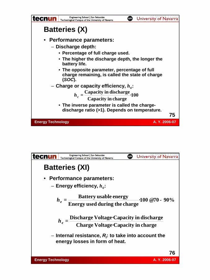
Batteries (X)• Performance parameters:
– Discharge depth:• Percentage of full charge used.• The higher the discharge depth, the longer the
battery life.• The opposite parameter, percentage of full
charge remaining, is called the state of charge(SOC).
– Charge or capacity efficiency, ηc:
• The inverse parameter is called the charge-discharge ratio (>1). Depends on temperature.
100·charge in Capacity
discharge in Capacity=cη
Energy Technology A. Y. 2006-07
76
Batteries (XI)• Performance parameters:
– Energy efficiency, ηc:
– Internal resistance, RI: to take into account theenergy losses in form of heat.
%9070100·charge the during used Energy
energy usable Battery−≅=eη
charge in pacityVoltage·Ca Chargedischarge in pacityVoltage·Ca Discharge
=eη
Energy Technology A. Y. 2006-07
77
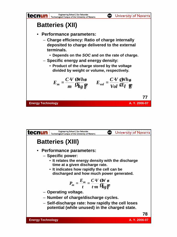
Batteries (XII)• Performance parameters:
– Charge efficiency: Ratio of charge internallydeposited to charge delivered to the externalterminals.
• Depends on the SOC and on the rate of charge.– Specific energy and energy density:
• Product of the charge stored by the voltagedivided by weight or volume, respectively.
=
=l
WhVol
VCE
kgWh
mVC
E volm·
·
Energy Technology A. Y. 2006-07
78
Batteries (XIII)• Performance parameters:
– Specific power:• It relates the energy density with the discharge
time at a given discharge rate.• It indicates how rapidly the cell can be
discharged and how much power generated.
– Operating voltage.– Number of charge/discharge cycles.– Self-discharge rate: how rapidly the cell loses
potential (while unused) in the charged state.
··
==kgW
mtVC
tE
P mm

Energy Technology A. Y. 2006-07
79
Batteries (XIV)• Performance parameters:
– Ragone plot: specific power versus specific energy.
Energy Technology A. Y. 2006-07
80
Batteries (XV)• Performance
parameters:– Ragone plot.

Energy Technology A. Y. 2006-07
81
Batteries (XVI)
Energy Technology A. Y. 2006-07
82
Hybrid electric vehicles (I)• Pollutant emisions reduction ⇒ development
of Hybrid Electric Vehicles (HEVs).• It is not possible a pure electric vehicle
powered by batteries only: for a 1,500 kg vehicle and a stored energy of 25 kWh it is necessary a Ni-Cd battery of 400 kg.
• Development of HEVs: utilizing either diesel or gasoline engines, alternative fuels (methanol, etahnol, LPG or CNG) engines, gas turbines, fuel cells or electric motors with an storage system (batteries or flywheels).

Energy Technology A. Y. 2006-07
83
Hybrid electric vehicles (II)• General diagram of a HEV:
Combustion
Engine
Transmission
Storage system
Generator
Electric Motor
Wheels
Wheels
Energy Technology A. Y. 2006-07
84
Hybrid electric vehicles (III)• Comparision between en Internal Combustion
Engine (ICE) and a HEV:
• There are three main types of configurations and designs of HEVs: series, parallel, and dual-mode.
ICE HEV Fuel 100 50 (+50)
Transmission losses -6 -6 Idling losses -11 0
Accessory loads -2 -2 Engine losses -65 -32
Regenerative braking 0 +4 Total energy remaining 16 14 (+50)

Energy Technology A. Y. 2006-07
85
Hybrid electric vehicles (IV)• Series HEV:
– Example:• A 22-foot bus owned and
operated by the Chattanooga Regional Area Transportation Authority (CARTA, Tennessee, USA).
• Vehicle manufactured by Advanced Vehicle Systems (AVS, http://www.avsbus.com).
• It has a Capstone turbine that rotates at 96,000 rpm and runs on compressed natural gas.
Energy Technology A. Y. 2006-07
86
Hybrid electric vehicles (V)• Series HEV:
– Entire drive power transmitted electrically.– May require larger batteries.– Requires on-board charging.– Requires some off-board charging.– Optimisation by separating engine speed from
vehicle speed.– Engine never idles, thus reduces overall
emissions.– Requires heavy-duty motor.
Energy Technology A. Y. 2006-07
87
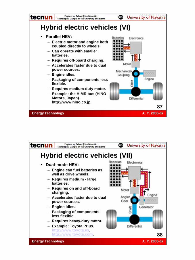
Hybrid electric vehicles (VI)• Parallel HEV:
– Electric motor and engine both coupled directly to wheels.
– Can operate with smaller batteries.
– Requires off-board charging.– Accelerates faster due to dual
power sources.– Engine idles.– Packaging of components less
flexible.– Requires medium-duty motor.– Example: the HIMR bus (HINO
Motors, Japan). http://www.hino.co.jp.
Energy Technology A. Y. 2006-07
88
Hybrid electric vehicles (VII)• Dual-mode HEV:
– Engine can fuel batteries as well as drive wheels.
– Requires medium - large batteries.
– Requires on and off-board charging.
– Accelerates faster due to dual power sources.
– Engine idles.– Packaging of components
less flexible.– Requires heavy-duty motor.– Example: Toyota Prius.
http://www.toyota.es. http://www.toyota.com.

Energy Technology A. Y. 2006-07
89
Hybrid electric vehicles (VIII)• Charge Sustaining and Charge Non-
Sustaining Hybrids:– Charge sustaining HEV: the hybrid power
source is capable of providing sufficient energy independent of the storage device to drive the vehicle just as it were a conventional vehicle.
– Charge non-sustaining HEV: the hybrid power source is only able to provide recharging energy and cannot supply the necessary energy to drive the vehicle by itself. This system must have additional energy from the storage device to meet the energy needs of the vehicle.
Energy Technology A. Y. 2006-07
90
Hybrid electric vehicles (IX)• Flywheel Energy Storage technology developed for NASA
by SatCon Technology Corporation plays a role in the drive train of experimental hybrid-electric automobiles.
• The SatCon Flywheel Energy Storage system provides 50 times the energy storage capacity of a conventional lead-acid battery.
Energy Technology A. Y. 2006-07
91
Reaction enthalpies (I)• Chemical reactions and other reversible
endothermic processes (solutions of solid in liquid and gas in solid).
• The energy is recovered with the inverse exothermic process. High storage density.
• Uses: at low temperature for the heating and air conditioning of buildings and at high temperature in power plants.
• Example:CO + Cl2 ⇔ COCl2 (fosgeno) ∆Ho = 112,6 kJ/g·mol
Energy Technology A. Y. 2006-07
92
Reaction enthalpies (II)• Example:
Ca(OH)2 (s) ⇔ CaO (s) + H2O (g) ∆Ho = 148,6 kJ/mol– Process:
1. Heat Ca(OH)2 from 25 ºC to 510 ºC: ∆Ho = +54,0 kJ/mol.
2. Decomposition at 510 ºC by heating: ∆Ho = +94,6 kJ/mol.
3. Cool the components to 25 ºC for storage only of the CaO: ∆Ho = -85 kJ/mol.
4. Add H2O (l) to close the cycle: ∆Ho = -63,6 kJ/mol.
– Efficiency: 63,6/148,6 = 42,8%.

Energy Technology A. Y. 2006-07
93
Reaction enthalpies (III)• Example:
CO + 3H2 ⇔ CH4 + H2O ∆Ho = 250,3 kJ/g·mol– Endothermic reaction from right to left.– For the inverse reaction at low T it is
necessary a catalyst ⇒ a long storage time.• Disadvantages:
– Development: it is necessary to work at high Tand a suitable catalyst.
– Security: storage at high P of poisonous andinflammable gases.
Energy Technology A. Y. 2006-07
94
Thermal storage methods• Wide T ranges: from refrigeration to 1.250 ºC.• Uses:
– Manufacture of cement, iron and steel, glass, aluminium, paper, plastics and rubbers.
– Food industry.– Air conditioning for buildings.
• Main problems:– To set a suitable surface for a fast heat
exchange.– Avoid heat leakages.

Energy Technology A. Y. 2006-07
95
Sensible heat (I)• The thermal energy is stored by raising the T
of some material (water, an organic liquid or a solid).
• Storage density:
• Materiales with high values of ρ·cp and α.• Disadvantages: working at variable T, small
density and possible volume variations(thermal expansion coefficient).
[ ]
=∆
33 · mJ
KTKkg
Jc
mkg
pρ
Energy Technology A. Y. 2006-07
96
Sensible heat (II)• Air conditioning: solid walls of high cp. Store
the energy during the day and return it during night.
• Water ponds to store solar heat for domestic hot water (d.h.w.) uses.
• Thermal power plants with steam turbine: pressured water. Excess of steam extracted from turbine and mixed with water ⇒pressured saturated water. Then it is re-evaporated and expanded in an auxiliary turbine. Storage T: 100 - 300º C.
Energy Technology A. Y. 2006-07
97
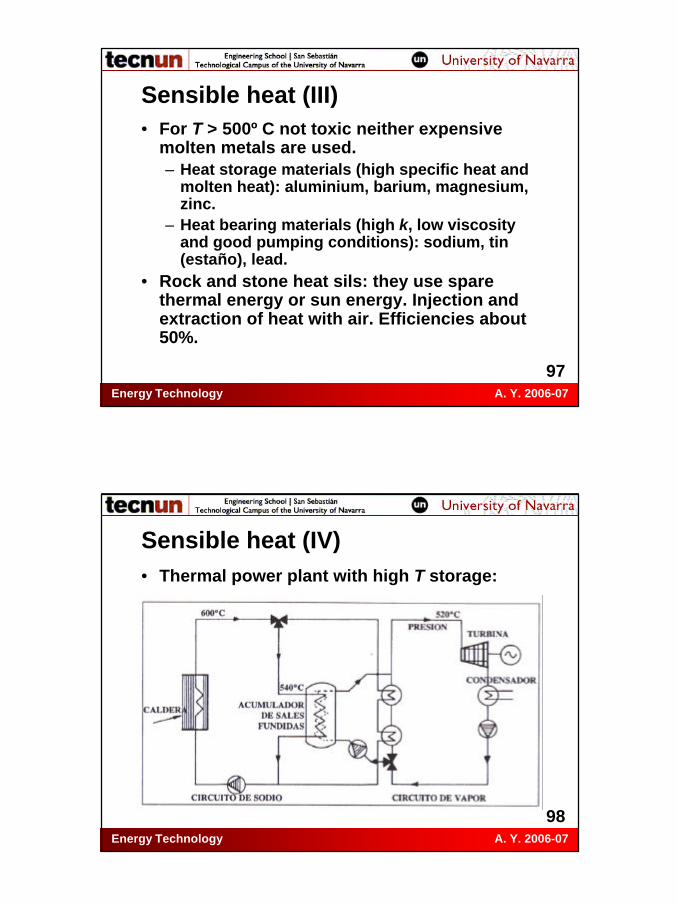
Sensible heat (III)• For T > 500º C not toxic neither expensive
molten metals are used.– Heat storage materials (high specific heat and
molten heat): aluminium, barium, magnesium, zinc.
– Heat bearing materials (high k, low viscosity and good pumping conditions): sodium, tin (estaño), lead.
• Rock and stone heat sils: they use spare thermal energy or sun energy. Injection and extraction of heat with air. Efficiencies about 50%.
Energy Technology A. Y. 2006-07
98
Sensible heat (IV)• Thermal power plant with high T storage:

Energy Technology A. Y. 2006-07
99
Sensible heat (V)• Heat sil:
Energy Technology A. Y. 2006-07
100
Sensible heat (VI)• Fireproof ball sils
and heat exchangers: sun concentrating collectors heat the balls (1,000-1,100º C), compressed air is heated with them and the air is expansioned in a turbine (900-1,000º C).

Energy Technology A. Y. 2006-07
101
Latent heat (I)• Energy stored by means of a phase change,
melting of a solid or vaporizing of a liquid. The energy is recovered with the inverse process, solidifying the liquid or condensing the steam.
• Storage density:
• Densities higher than in sensible heat.• Advantages: process at a constant T, without
volume change and with a wide variety of materials and working T.
=
3..3 mJ
kgJ
mkg
fcλρ
Energy Technology A. Y. 2006-07
102
Latent heat (II)• It can be combined with the storage by means of
sensible heat.• Maximum storage capacity: water vaporization
(2,257 J/kg), but the problem is to store the steam in a suitable container. It is not used.
• Phase Change Materials (PCMs): they can be organic or inorganic.
• Disadvantages:– The organic materials suffer a great change of
volume.– The inorganic materials have problems of
corrosion of metals and of stability after a lot of cycles.

Energy Technology A. Y. 2006-07
103
Latent heat (III)• Materials requirements:
– High phase change latent heat.– Suitable properties during the phase change.– High k.– Storage easiness.– Stability.– Absence of toxicity.– Low cost.
• Best material: eutectic fluorine mix (Tf = 680 ºC and density = 1,500 MJ/m3). But problems of corrosion and erosion due to the entry of oxygen and steam during the heat exchanges.
Energy Technology A. Y. 2006-07
104
Latent heat (IV)• Applications:
– Preservation and transport of temperature sensitive materials (biomedic products, organs, plants, electronic components...).
– Building heating and air conditioning applications.
– Water storage tanks (to avoid stratifying due to density variations).
– In air-air heat pumps to increase COP.
• In power plants is not used ⇒ there is no suitable material for a large scale storage.

Energy Technology A. Y. 2006-07
105
Capacitors• Simpler system to store electric energy. It
absorbs electric charges when subject to an electric field. A dielectric material between two plates.
• Stored energy:• Volume unit energy:• It depends on the dielectric material.
Currently densities of 0.15 Wh/m3 with a field of 10 million of V/m.
• Advantage of the capacitors: huge power density supply when short-circuited.
2/2CVE =dVEV 2/2ε=
Energy Technology A. Y. 2006-07
106
Magnetic fields (I)• A coil conected to a voltage source ⇒
intensity provokes a magnetic field. Thisenergy absorption can be released as a electric current in other circuit.
• Stored energy in the solenoid:• Volume unit energy:• Dense coils and materials with high values of
magnetic permitivity are needed.• Disadvantages: density values similar to
capacitors and they unload quickly if theelectric field stops.
µ2/2VBE =LINEV 2/22µ=

Energy Technology A. Y. 2006-07
107
Magnetic fields (II)• Materials called superconductors are being
investigated: at T close to 0 K show electricresistance null and high magnetic permitivity.
• Critical temperatures between –263 and –253 ºC. Criogenic tanks of liquid He vacuuminsulated.
• With the superconductors the current can be cut and the energy can be stored, theoretically, until infinity.
• Global efficiencies higher than 90%. Thefuture choice.
Energy Technology A. Y. 2006-07
108
Bibliography• Vicente Bermúdez et al., Tecnología
Energética, Servicio de Publicaciones de la Universidad Politécnica de Valencia, Valencia, 2000.
• F. Jarabo et al., El Libro de las Energías Renovables, 2ª Edición, S. A. de Publicaciones Técnicas, Madrid, 1991.
• Reiner Decher, Energy Conversion, Oxford University Press, New York, 1994.