lem transducers application note generic mounting rules · page 2 lem transducers generic mounting...
TRANSCRIPT
N°ANE120504/1
Ap
plic
atio
n N
ote
Contents1 Introduction 12 Mechanical theory and mounting method choice 13 Design rules for customer’s support 24 Choice of fastening hardware 45 Screw torque 76 Material compatibility 87 Ideal LEM configuration 9
List of figuresFig. 1: Transducer mounted on the primary bar OR using housing brackets 1
Fig. 2: Transducer mounted horizontally OR vertically 2
Fig. 3: First contact zone between LEM transducer and customer’s support badly located 2
Fig. 4: Badly designed customer’s support effect on LEM transducer’s bracket 2
Fig. 5: Local insert effect on customer’s support around screw head 3
Fig. 6: Insufficient contact on customer’s support around screw head 3
Fig.7: Examples of non flat customer support design around screw zone 3
Fig. 8: Screw axis not perpendicular to contact surface on customer’s support 4
Fig. 9: Washer types allowed for direct contact with LEM transducer’s brackets 4
Fig. 10: Large head screw example integrating washer function 5
Fig. 11: Potential risk due to the use of double washer mounting 5
Fig. 12: Loosening torque after 500 h at 23°C with self-locking system or elastic washer 6
Fig. 13 : Torque loss with standard ISO metric screw+flat plain washer at 23°C. 7
Fig. 14 : Corrosion effect on transducer secondary connection with badly chosen nuts. 8
Fig. 15 : Metals galvanic compatibility chart. 9
1. Introduction
The aim of this document is to explain which rules the customers have to respect when mounting LEM transducers in their applications. Respecting the rules described below will guarantee a good mounting of the product in its environment and a good behavior in time.
This document only concerns mechanical mounting of the transducers. For example, rules concerning electrical connections, electromagnetic environment… etc are not described here.
LEM Transducers Generic Mounting Rules
2. Mechanical theory and mounting method choice
When a solid object has to be mounted perfectly (no possible motion), you only have to constrain six possible movement modes, called DOF (“degrees of freedom”). For example, defining one point position (three translations) and orientation (three angles) enables to know exactly the position of an object in space.
Theoretically speaking, when less than six DOFs are blocked, the system is hypostatic and some possible motion modes remain. When more than six DOFs are constrained, the system is hyperstatic, that is to say, more constraints than necessary to mount the part are used and there is a risk of over-stressing it.
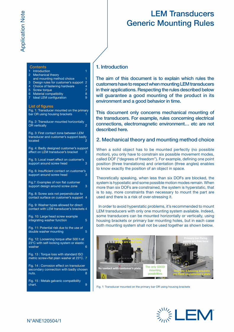
In order to avoid hyperstatic problems, it’s recommended to mount LEM transducers with only one mounting system available. Indeed, some transducers can be mounted horizontally or vertically, using housing brackets or primary bar mounting holes, but in each case both mounting system shall not be used together as shown below.
No contact with customer’s plate
Primary bar fixing points are free here
Only the 4 housing brackets are fixed on customer’s plate
Only primary bar fixing points are used here
The only GOOD mounting
possibilities
Fig. 1: Transducer mounted on the primary bar OR using housing brackets
Page 2
LEM
Tra
nsd
ucer
s G
ener
ic M
ount
ing
Rul
es Design rulesfor customer’s support
3 Design rules for customer´s support
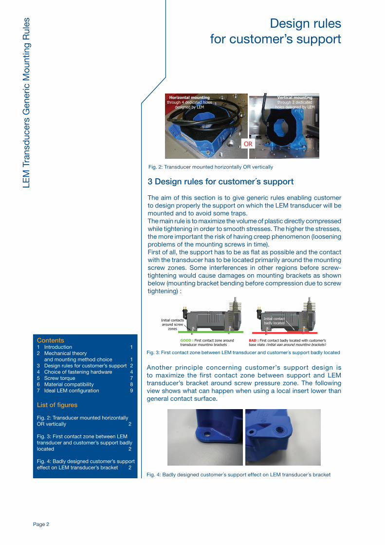
The aim of this section is to give generic rules enabling customer to design properly the support on which the LEM transducer will be mounted and to avoid some traps.The main rule is to maximize the volume of plastic directly compressed while tightening in order to smooth stresses. The higher the stresses, the more important the risk of having creep phenomenon (loosening problems of the mounting screws in time).First of all, the support has to be as flat as possible and the contact with the transducer has to be located primarily around the mounting screw zones. Some interferences in other regions before screw-tightening would cause damages on mounting brackets as shown below (mounting bracket bending before compression due to screw tightening) :
Another principle concerning customer’s support design is to maximize the first contact zone between support and LEM transducer’s bracket around screw pressure zone. The following view shows what can happen when using a local insert lower than general contact surface.
GOOD : First contact zone around transducer mounting brackets
BAD : First contact badly located with customer’s base plate (initial gap around mounting brackets)
Initial contacts around screw
zones
Initial contact badly located
OR
Horizontal mounting through 4 dedicated holes
designed by LEM
Vertical mounting through 2 dedicated
holes designed by LEM
Fig. 2: Transducer mounted horizontally OR vertically
Fig. 4: Badly designed customer´s support effect on LEM transducer´s bracket
Fig. 3: First contact zone between LEM transducer and customer´s support badly located
Contents1 Introduction 12 Mechanical theory and mounting method choice 13 Design rules for customer’s support 24 Choice of fastening hardware 45 Screw torque 76 Material compatibility 87 Ideal LEM configuration 9
List of figures
Fig. 2: Transducer mounted horizontally OR vertically 2
Fig. 3: First contact zone between LEM transducer and customer’s support badly located 2
Fig. 4: Badly designed customer’s support effect on LEM transducer’s bracket 2
Page 3
LEM
Tra
nsd
ucer
s G
ener
ic M
ount
ing
Rul
es Design rules for customer’s support
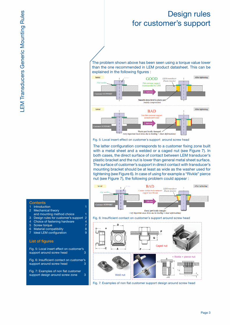
The problem shown above has been seen using a torque value lower than the one recommended in LEM product datasheet. This can be explained in the following figures :
The latter configuration corresponds to a customer fixing zone built with a metal sheet and a welded or a caged nut (see Figure 7). In both cases, the direct surface of contact between LEM transducer’s plastic bracket and the nut is lower than general metal sheet surface.The surface of customer’s support in direct contact with transducer’s mounting bracket should be at least as wide as the washer used for tightening (see Figure 6). In case of using for example a “Rivkle” pierce nut (see Figure 7), the following problem could appear :
Caged nut
Weld nut
« Rivkle » pierce nut
Fig. 6: Insufficient contact on customer´s support around screw head
Fig. 7: Examples of non flat customer support design around screw head
Fig. 5: Local insert effect on customer´s support around screw head
Contents1 Introduction 12 Mechanical theory and mounting method choice 13 Design rules for customer’s support 24 Choice of fastening hardware 45 Screw torque 76 Material compatibility 87 Ideal LEM configuration 9
List of figures
Fig. 5: Local insert effect on customer’s support around screw head 3
Fig. 6: Insufficient contact on customer’s support around screw head 3
Fig. 7: Examples of non flat customer support design around screw zone 3
Page 4
LEM
Tra
nsd
ucer
s G
ener
ic M
ount
ing
Rul
es Design rules for customer’s support
Choice of fasteninghardware
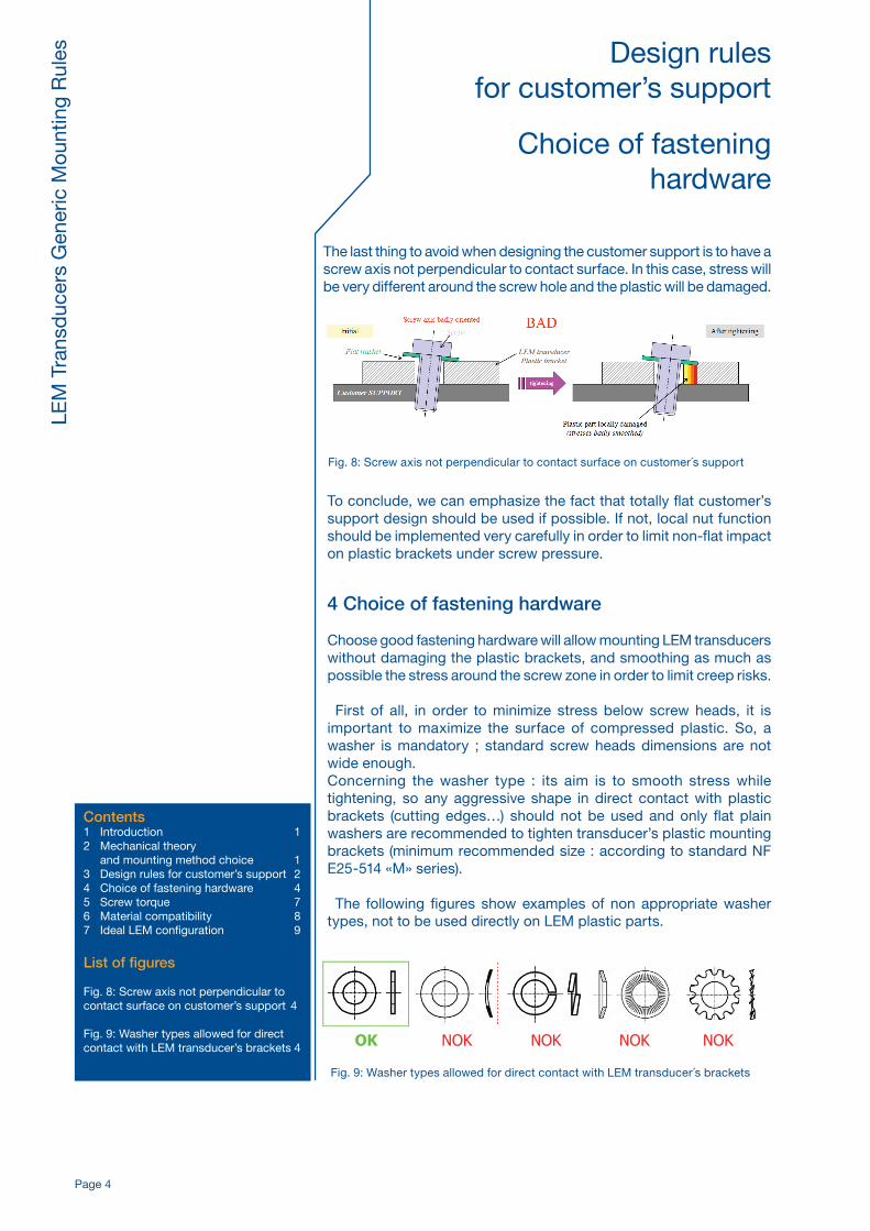
The last thing to avoid when designing the customer support is to have a screw axis not perpendicular to contact surface. In this case, stress will be very different around the screw hole and the plastic will be damaged.
To conclude, we can emphasize the fact that totally flat customer’s support design should be used if possible. If not, local nut function should be implemented very carefully in order to limit non-flat impact on plastic brackets under screw pressure.
4 Choice of fastening hardware
Choose good fastening hardware will allow mounting LEM transducers without damaging the plastic brackets, and smoothing as much as possible the stress around the screw zone in order to limit creep risks.
First of all, in order to minimize stress below screw heads, it is important to maximize the surface of compressed plastic. So, a washer is mandatory ; standard screw heads dimensions are not wide enough.Concerning the washer type : its aim is to smooth stress while tightening, so any aggressive shape in direct contact with plastic brackets (cutting edges…) should not be used and only flat plain washers are recommended to tighten transducer’s plastic mounting brackets (minimum recommended size : according to standard NF E25-514 «M» series).
The following figures show examples of non appropriate washer types, not to be used directly on LEM plastic parts.
OK NOK NOK NOK NOK
Fig. 8: Screw axis not perpendicular to contact surface on customer´s support
Fig. 9: Washer types allowed for direct contact with LEM transducer´s brackets
Contents1 Introduction 12 Mechanical theory and mounting method choice 13 Design rules for customer’s support 24 Choice of fastening hardware 45 Screw torque 76 Material compatibility 87 Ideal LEM configuration 9
List of figures
Fig. 8: Screw axis not perpendicular to contact surface on customer’s support 4
Fig. 9: Washer types allowed for direct contact with LEM transducer’s brackets 4
Page 5
LEM
Tra
nsd
ucer
s G
ener
ic M
ount
ing
Rul
es Choice of fasteninghardware
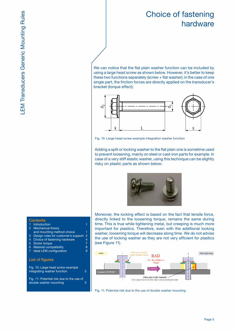
We can notice that the flat plain washer function can be included by using a large head screw as shown below. However, it’s better to keep these two functions separately (screw + flat washer); in the case of one single part, the friction forces are directly applied on the transducer’s bracket (torque effect).
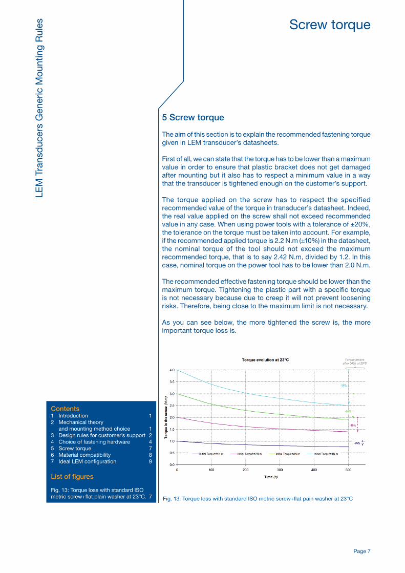
Adding a split or locking washer to the flat plain one is sometime used to prevent loosening, mainly on steel or cast-iron parts for example. In case of a very stiff elastic washer, using this technique can be slightly risky on plastic parts as shown below:
Moreover, the locking effect is based on the fact that tensile force, directly linked to the loosening torque, remains the same during time. This is true while tightening metal, but creeping is much more important for plastics. Therefore, even with the additional locking washer, loosening torque will decrease along time. We do not advise the use of locking washer as they are not very efficient for plastics (see Figure 11).
Fig. 10: Large head screw example integration washer function
Fig. 11: Potential risk due to the use of double washer mounting
Contents1 Introduction 12 Mechanical theory and mounting method choice 13 Design rules for customer’s support 24 Choice of fastening hardware 45 Screw torque 76 Material compatibility 87 Ideal LEM configuration 9
List of figures
Fig. 10: Large head screw example integrating washer function 5
Fig. 11: Potential risk due to the use of double washer mounting 5

Page 6
LEM
Tra
nsd
ucer
s G
ener
ic M
ount
ing
Rul
es Choice of fasteninghardware
Another way to prevent loosening is to use safety self-locking nuts or screws. In this case, anti-loosening system consists in adding a high friction material located in the thread zone. Even if plastic creeps, the necessary torque needed to loosen the screw remains higher than with lock washer solution.
The following graph shows the loss of tightening torque when tightening a typical LEM transducer mounting bracket at two different initial torques (1 or 3 N.m) : • With only “standard” flat plain washer, • With NF flat plain washer and lock washer, • With NF flat washer + safety self-locking nut.
As we can see above, “Nilstop” self-locking nut is a better way to prevent loosening on plastic parts than a lock washer. The lock washer uses plastic reaction below the screw head to prevent loosening but loosening is due to the fact that plastic creeps: its stiffness decreases in the time.Adding a lock washer has a very low impact concerning loosening risks. Self-locking nuts don’t work the same way: it adds a new friction torque due to the contact with elastomeric coating in the thread zone that is not directly impacted by bracket-plastic creeping.Finally, we can state that the wider the contact surface area between washer and plastic is, the more important maximum torque is. The simplified one dimension approach even shows that maximum torque is nearly proportional to this surface area.So, one way to improve acceptable torque by 50% is to increase the compressed surface area (surface of contact between plain washer and the plastic bracket…) by the same percentage.
Fig. 12: Loosening torque after 500h at 23°C with self-locking system or elastic washer
Contents1 Introduction 12 Mechanical theory and mounting method choice 13 Design rules for customer’s support 24 Choice of fastening hardware 45 Screw torque 76 Material compatibility 87 Ideal LEM configuration 9
List of figures
Fig. 12: Loosening torque after 500 h at 23°C with self-locking system or elastic washer 6
Page 7
LEM
Tra
nsd
ucer
s G
ener
ic M
ount
ing
Rul
es Screw torque
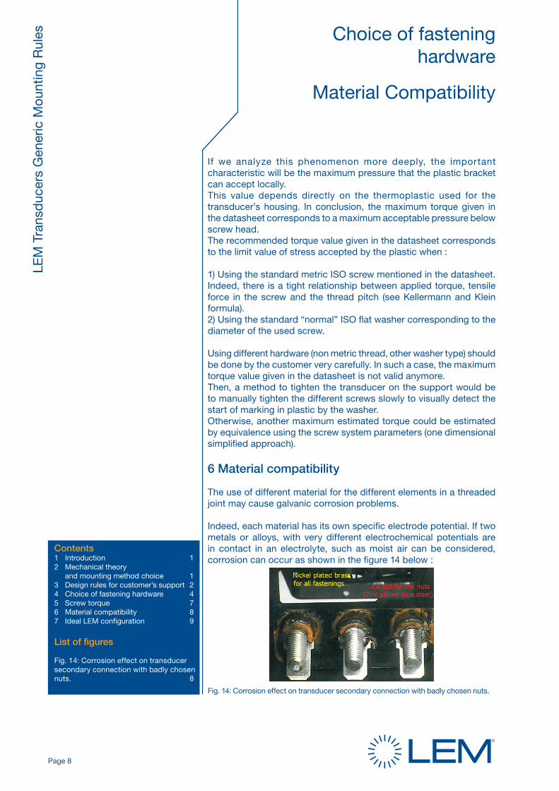
Fig. 13: Torque loss with standard ISO metric screw+flat pain washer at 23°C
Contents1 Introduction 12 Mechanical theory and mounting method choice 13 Design rules for customer’s support 24 Choice of fastening hardware 45 Screw torque 76 Material compatibility 87 Ideal LEM configuration 9
List of figures
Fig. 13: Torque loss with standard ISO metric screw+flat plain washer at 23°C. 7
5 Screw torque
The aim of this section is to explain the recommended fastening torque given in LEM transducer’s datasheets.
First of all, we can state that the torque has to be lower than a maximum value in order to ensure that plastic bracket does not get damaged after mounting but it also has to respect a minimum value in a way that the transducer is tightened enough on the customer’s support.
The torque applied on the screw has to respect the specified recommended value of the torque in transducer’s datasheet. Indeed, the real value applied on the screw shall not exceed recommended value in any case. When using power tools with a tolerance of ±20%, the tolerance on the torque must be taken into account. For example, if the recommended applied torque is 2.2 N.m (±10%) in the datasheet, the nominal torque of the tool should not exceed the maximum recommended torque, that is to say 2.42 N.m, divided by 1.2. In this case, nominal torque on the power tool has to be lower than 2.0 N.m.
The recommended effective fastening torque should be lower than the maximum torque. Tightening the plastic part with a specific torque is not necessary because due to creep it will not prevent loosening risks. Therefore, being close to the maximum limit is not necessary.
As you can see below, the more tightened the screw is, the more important torque loss is.
Page 8
LEM
Tra
nsd
ucer
s G
ener
ic M
ount
ing
Rul
es Choice of fasteninghardware
Material Compatibility
If we analyze this phenomenon more deeply, the important characteristic will be the maximum pressure that the plastic bracket can accept locally. This value depends directly on the thermoplastic used for the transducer’s housing. In conclusion, the maximum torque given in the datasheet corresponds to a maximum acceptable pressure below screw head.The recommended torque value given in the datasheet corresponds to the limit value of stress accepted by the plastic when :
1) Using the standard metric ISO screw mentioned in the datasheet. Indeed, there is a tight relationship between applied torque, tensile force in the screw and the thread pitch (see Kellermann and Klein formula).2) Using the standard “normal” ISO flat washer corresponding to the diameter of the used screw.
Using different hardware (non metric thread, other washer type) should be done by the customer very carefully. In such a case, the maximum torque value given in the datasheet is not valid anymore.Then, a method to tighten the transducer on the support would be to manually tighten the different screws slowly to visually detect the start of marking in plastic by the washer. Otherwise, another maximum estimated torque could be estimated by equivalence using the screw system parameters (one dimensional simplified approach).
6 Material compatibility
The use of different material for the different elements in a threaded joint may cause galvanic corrosion problems.
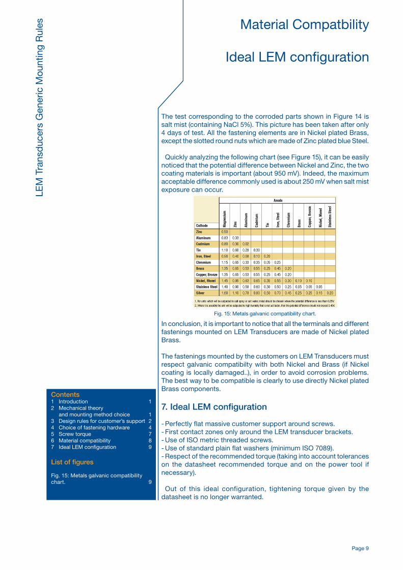
Indeed, each material has its own specific electrode potential. If two metals or alloys, with very different electrochemical potentials are in contact in an electrolyte, such as moist air can be considered, corrosion can occur as shown in the figure 14 below :
Fig. 14: Corrosion effect on transducer secondary connection with badly chosen nuts.
Contents1 Introduction 12 Mechanical theory and mounting method choice 13 Design rules for customer’s support 24 Choice of fastening hardware 45 Screw torque 76 Material compatibility 87 Ideal LEM configuration 9
List of figures
Fig. 14: Corrosion effect on transducer secondary connection with badly chosen nuts. 8
Page 9
LEM
Tra
nsd
ucer
s G
ener
ic M
ount
ing
Rul
es Material Compatbility
Ideal LEM configuration
Contents1 Introduction 12 Mechanical theory and mounting method choice 13 Design rules for customer’s support 24 Choice of fastening hardware 45 Screw torque 76 Material compatibility 87 Ideal LEM configuration 9
List of figures
Fig. 15: Metals galvanic compatibility chart. 9
The test corresponding to the corroded parts shown in Figure 14 is salt mist (containing NaCl 5%). This picture has been taken after only 4 days of test. All the fastening elements are in Nickel plated Brass, except the slotted round nuts which are made of Zinc plated blue Steel.
Quickly analyzing the following chart (see Figure 15), it can be easily noticed that the potential difference between Nickel and Zinc, the two coating materials is important (about 950 mV). Indeed, the maximum acceptable difference commonly used is about 250 mV when salt mist exposure can occur.
Fig. 15: Metals galvanic compatibility chart.
In conclusion, it is important to notice that all the terminals and different fastenings mounted on LEM Transducers are made of Nickel plated Brass.
The fastenings mounted by the customers on LEM Transducers must respect galvanic compatibilty with both Nickel and Brass (if Nickel coating is locally damaged..), in order to avoid corrosion problems. The best way to be compatible is clearly to use directly Nickel plated Brass components.
7. Ideal LEM configuration
- Perfectly flat massive customer support around screws.- First contact zones only around the LEM transducer brackets.- Use of ISO metric threaded screws.- Use of standard plain flat washers (minimum ISO 7089).- Respect of the recommended torque (taking into account tolerances on the datasheet recommended torque and on the power tool if necessary).
Out of this ideal configuration, tightening torque given by the datasheet is no longer warranted.