leica sp8 basic image acquisition laser scanning confocal sp8 basic... · basic image acquisition...
TRANSCRIPT

Leica SP8 Basic Image AcquisitionLaser Scanning Confocal
Kim Peifley
02/03/17

General Information

Available Lasers:
• 405nm
• 488nm
• 552nm
• 638nm
Available Objectives:
• 2.5x Dry
• 5x Dry
• 10x Dry
• 20x Multi- Immersion
• 63x Oil
• 100x Oil
Laser and Objective Information:

3 Color Image Acquisition

This is the acquisition work area.

1. On the top of the work area - Click Configuration.
2. Click the Laser Configuration button.
3. Turn on all the lasers.
The lasers available on this microscope are: 405nm, 488nm, 552nm, 638nm.
1
2
3

4. Click Acquire.
5. One way to set your light paths is to click on Leica Settings.
6. Select the dyes you are using.
7. You can also save your own settings. Click the save icon to create a user setting.
8. An alternative way is to click on the Dye assistant icon.
4
5
6
7
8

9. In dye assistant click on the … box.
10. Click on the dye you are using.
11. Repeat for all the dyes you have.
12. You will now see a listing of possible light path set ups. The
bottom one “Frame or track sequential” is similar to what we use
on the Zeiss microscopes.
13. Click the Apply button in that window.
9
10
12
13

14. You can adjust your emissions filters by clicking on the Sequence you wish to adjust. Seq1 in this example.
15. Click on the end of the filter and drag it to where you wish to have it.
16. The numbers on the bottom indicate the emission wavelength at that point.
17. Repeat for other Sequences.
14 16
15
16

Alternative way to change emission filter settings:
Click on the end of the emission filter
and a window will appear. You can type
in the number or use the arrows to
adjust the filter.

There are two ways to select the objective:
1. From the software: Click the Objective window and select from the drop down menu.
2. From the microscope touch screen: Select the Objective Icon. Then Select the objective you want.
The selected objective is highlighted in red.
1
2

If you click on the objective icon next
to the objective window it will open up
the Objective Configuration window.
This will give you the details of the
selected objective.

18. Clean the objective using lens paper and Sparkle.
19. Place oil on the slide or on the objective.
20. Place sample on microscope and use the clips to secure it in place.
21. Raise the objective by turning the focus knob away from you.
20
FineCourse
21
19
FineCourse
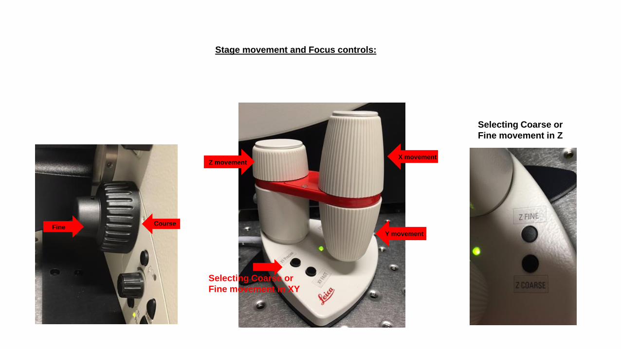
Stage movement and Focus controls:
Selecting Coarse or
Fine movement in Z
Z movement
Y movement
X movement
Selecting Coarse or
Fine movement in XY
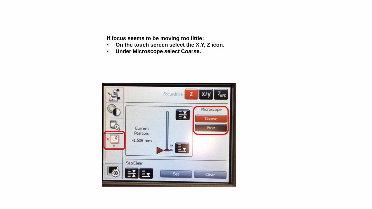
If focus seems to be moving too little:
• On the touch screen select the X,Y, Z icon.
• Under Microscope select Coarse.
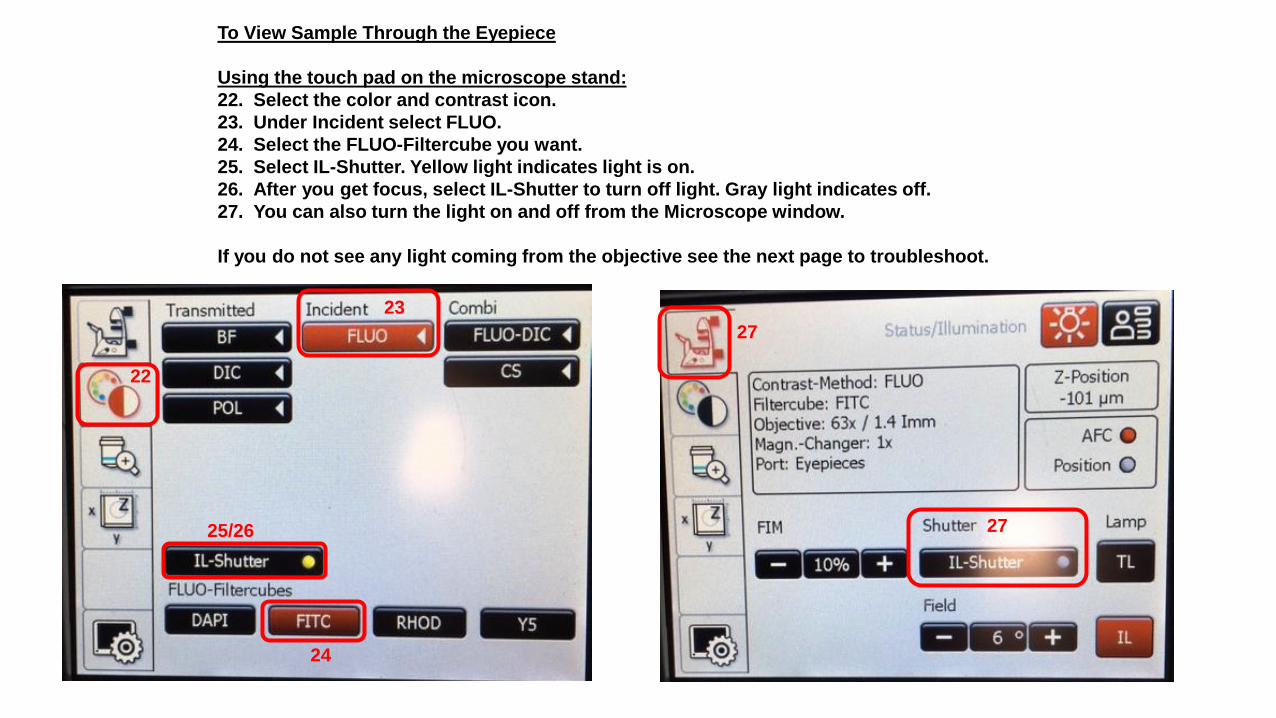
To View Sample Through the Eyepiece
Using the touch pad on the microscope stand:
22. Select the color and contrast icon.
23. Under Incident select FLUO.
24. Select the FLUO-Filtercube you want.
25. Select IL-Shutter. Yellow light indicates light is on.
26. After you get focus, select IL-Shutter to turn off light. Gray light indicates off.
27. You can also turn the light on and off from the Microscope window.
If you do not see any light coming from the objective see the next page to troubleshoot.
22
23
24
25/26 27
27

If you do not see any light coming from the objective.
• Check the light source box. The Intensity is likely too low. Turn it up. The second white dot is usually good enough.
• On the microscope check the side of the condenser arm. It should be Brightfield not Digital Lightsheet.

On the Microscope Touch Screen:
• Select the Objective Window.
• Check the “Port:” section – it should be the Eyepiece
icon in red not the camera icon.
Side port cameraEye piece

If you have a very small viewing area:
• Select Microscope icon on the touch pad.
• Adjust the Field by pressing the + button.
• A field of 6º is good.

Control Panel
Located beneath the monitor.
When you hit either high or low limit
of any control you will hear beeps.
Smart Gain:
Adjust the gain.
Zoom:
Adjust the Zoom.
Z Position:
Focus adjustment
and to set Z stack
Scan Field Rotate:
Rotating the field
of view.
Smart Offset:
Adjust the offset.
Pinhole:
Adjust pinhole
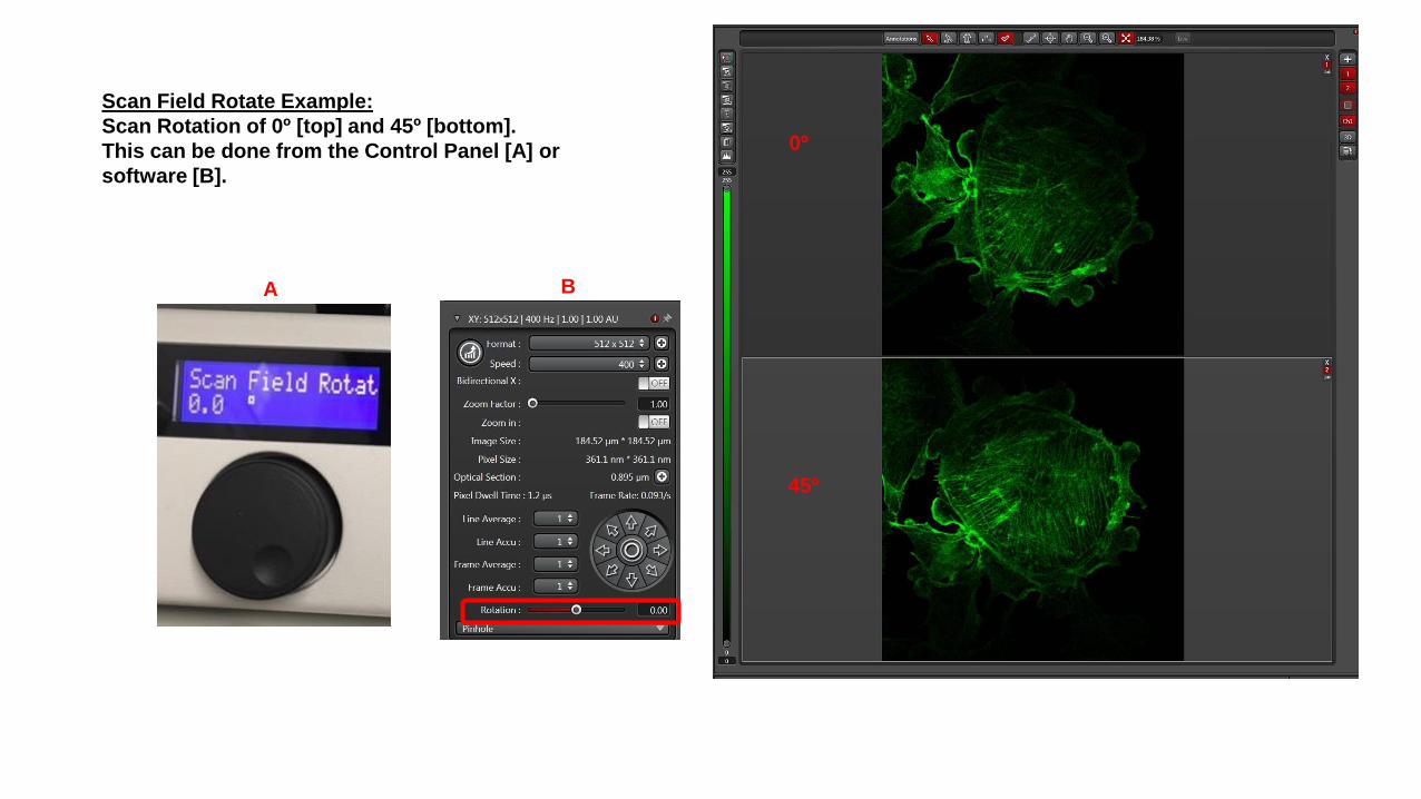
Scan Field Rotate Example:
Scan Rotation of 0º [top] and 45º [bottom].
This can be done from the Control Panel [A] or
software [B].
0º
45º
A B
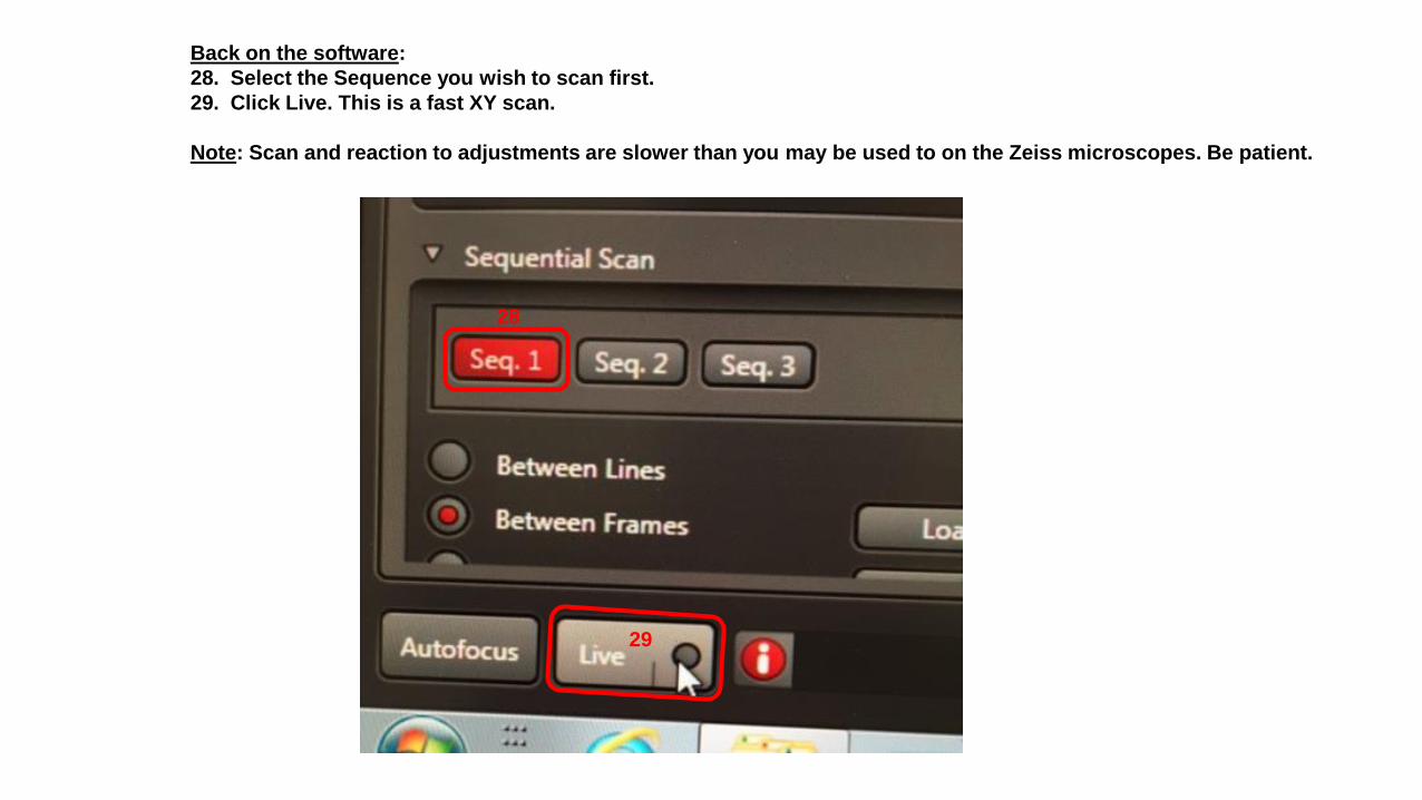
Back on the software:
28. Select the Sequence you wish to scan first.
29. Click Live. This is a fast XY scan.
Note: Scan and reaction to adjustments are slower than you may be used to on the Zeiss microscopes. Be patient.
28
29

30. Click the LUT button.
31. Blue is saturation. Green is below detection [not seen here].
30
31
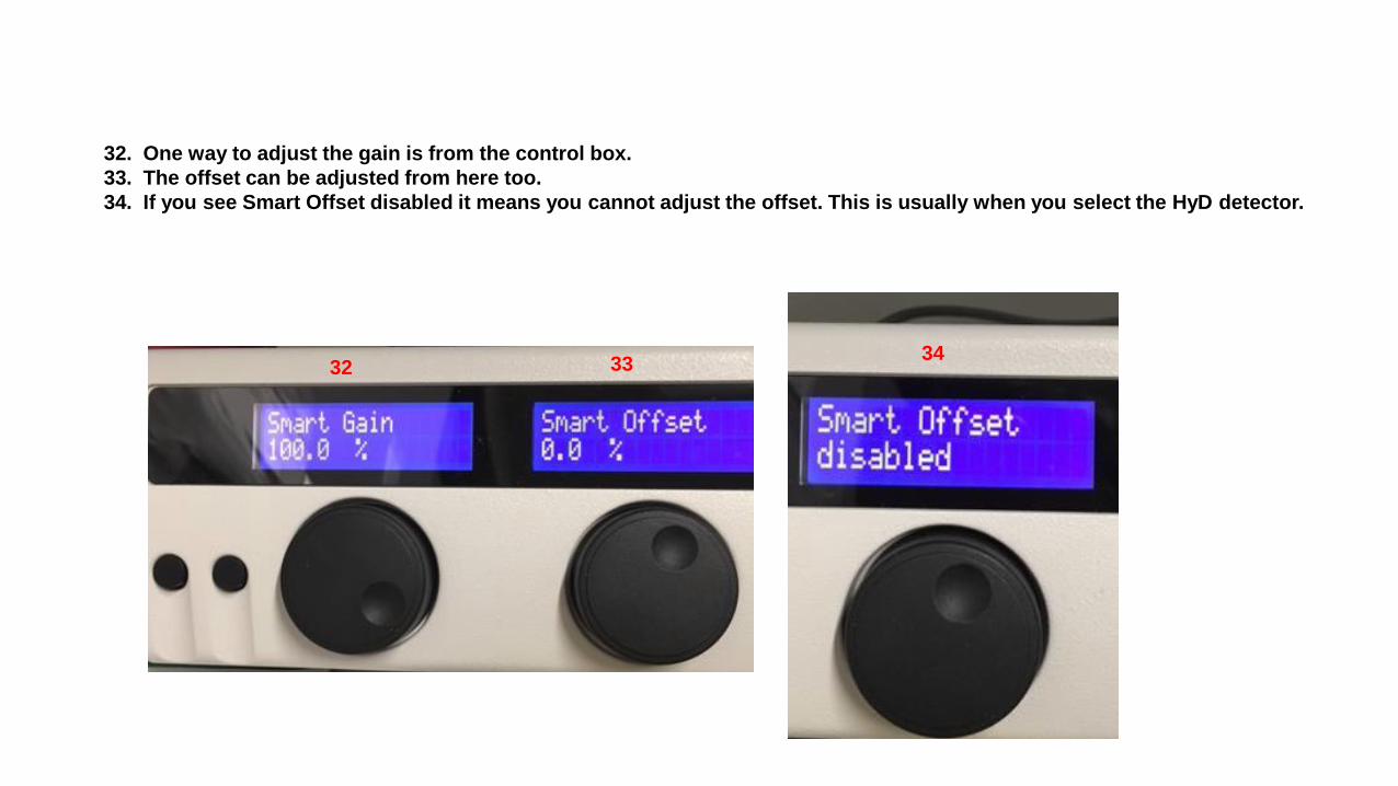
32. One way to adjust the gain is from the control box.
33. The offset can be adjusted from here too.
34. If you see Smart Offset disabled it means you cannot adjust the offset. This is usually when you select the HyD detector.
32 3334

35. Another way to adjust the gain is to click on the gain in the software which brings
up a slider. You can use the mouse to move the slider or the scroll bar on the
mouse to adjust the gain.
36. Select the next Sequence and repeat the steps.
37. Repeat until you have gone through all your dyes.
35
36
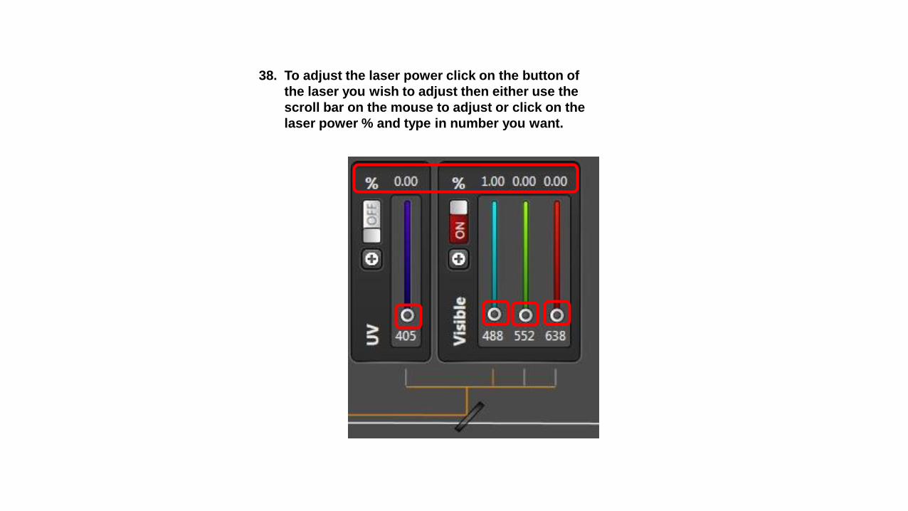
38. To adjust the laser power click on the button of
the laser you wish to adjust then either use the
scroll bar on the mouse to adjust or click on the
laser power % and type in number you want.
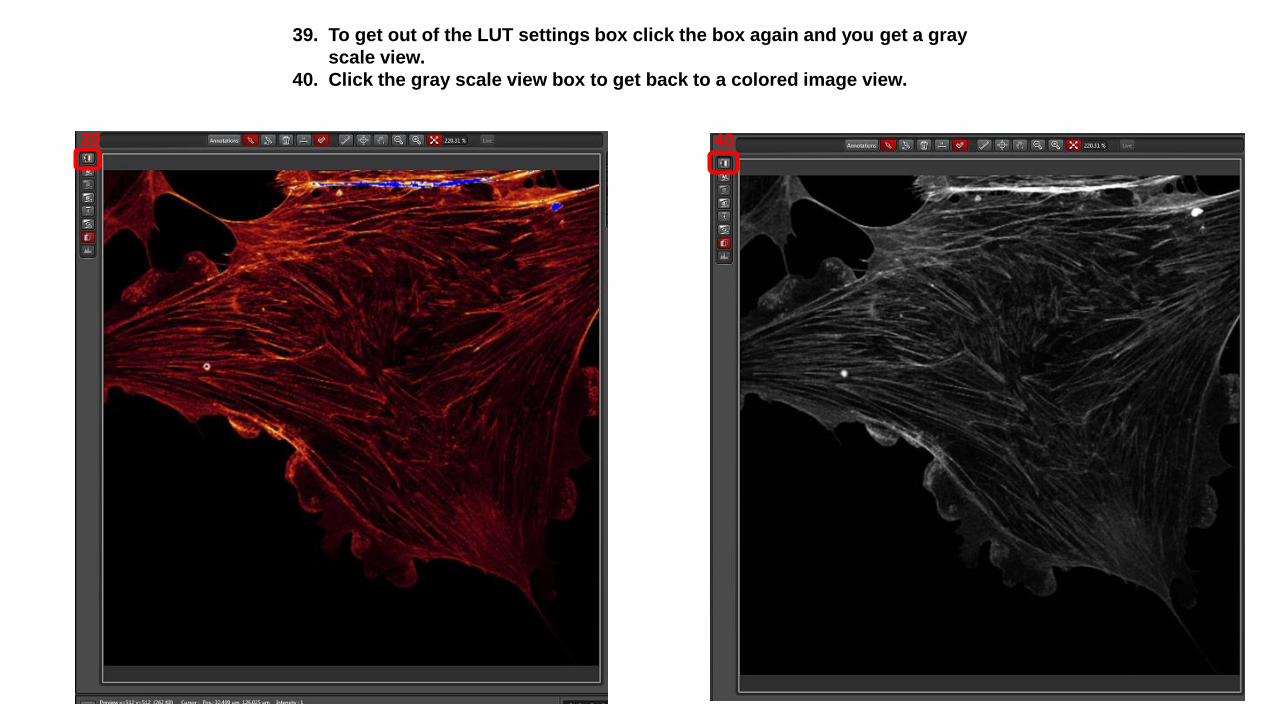
39. To get out of the LUT settings box click the box again and you get a gray
scale view.
40. Click the gray scale view box to get back to a colored image view.
39 40

41. The Pinhole can be adjusted from the Control Panel [A] or from the software [B].
A BBB

Selecting the Frame Average:
42. Go to the Frame Average window
43. From the drop down menu select 4.
44. See the average you selected in the window.
Frame average will collect sequence 1 then 2 then 3 and repeat this 4 times for the average.
4243 44

If you wish to Select the Line Average instead:
42. Go to the Line Average window
43. From the drop down menu select 4.
44. See the average you selected in the window.
Line average will create Sequence 1 4 times for the average and then repeat for other sequences.
4243
44

45. Click Start to acquire a multi-color image.
46. Click Capture Image to get a single color image. The color will be the Sequence that is selected. In this case Seq. 2.
46
4645
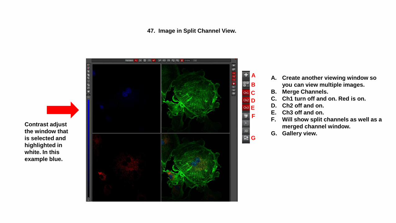
47. Image in Split Channel View.
Contrast adjust
the window that
is selected and
highlighted in
white. In this
example blue.
A. Create another viewing window so
you can view multiple images.
B. Merge Channels.
C. Ch1 turn off and on. Red is on.
D. Ch2 off and on.
E. Ch3 off and on.
F. Will show split channels as well as a
merged channel window.
G. Gallery view.
B
C
E
F
A
D
G

48. Image in Merge View.
E
A
D
F
C
B A. Create another viewing window so
you can view multiple images.
B. Split Channels.
C. Ch1 turn off and on. Red is on.
D. Ch2 off and on.
E. Ch3 off and on.
F. Gallery view.
Rotate
between
color, LUT
and gray
scale view
Add scale bar Zoom in and out

To Save Your Configuration:
1. Next to Leica Settings window
click on the floppy disc. If you
hover over it you will see Save
current Settings.
2. This opens up a window and you
will see Default_Name_1
3. Enter a configuration name.
4. Click ok.
5. Now when you click Leica
Settings you will see your
configuration.
6. Highlight and click to load the
configuration.
1
2 3
4
5
6

Saving Projects and Images

Saving Image:
1. Click Open Projects Tab.
2. Highlight Project you wish to save..
3. Click on floppy disc icon to right of Project
name. If you hover the mouse over it you
will see Save Project.
1
2
3
3

4. Select the Data (E:) drive to save data locally.
5. Select your folder or create a folder with your
name.
6. Click on folder to open.
7. Create folder for today’s work.
8. Click on that folder to open it.5
7
4

8. Name your project.
9. Click Save.
9
8

10. The project is now named. In this example Invitrogen Slide 1. All images
acquired will be listed under this project.

11. To name your image highlight
image and right click to get menu.
12. Select Rename.
13. Window will be highlights so you
can type in new name.
14. Hit enter to see name.11
12
13 14
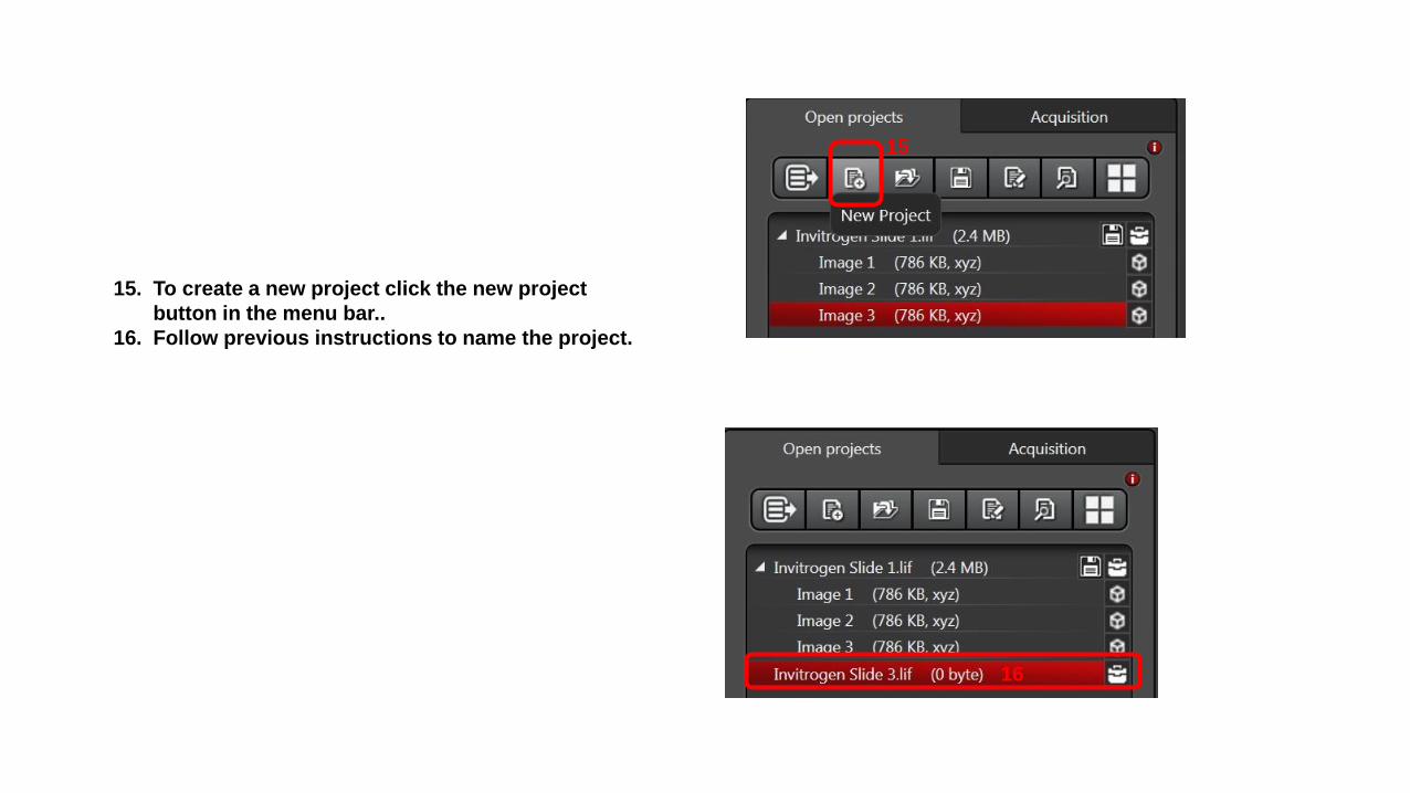
15. To create a new project click the new project
button in the menu bar..
16. Follow previous instructions to name the project.
15
16

17. This shows all the projects and images named for one imaging session.

To export images:
1. Make sure you are in Open Projects tab.
2. Highlight Image you want to Export.
3. Right click for menu and select Export.
1
2
3

4. Select file type you wish to save image as.
5. In Export to JPEG window click Browse.
6. Select the Destination file.
7. Click OK.
4
5
6
7

8. Check to make sure Destination folder
shows the folder you selected.
9. Make any selections you wish to have.
10. If you want a Scale Bar make sure the
“Micron Scale” box is checked.
11. Click Save.
8
9
10
11
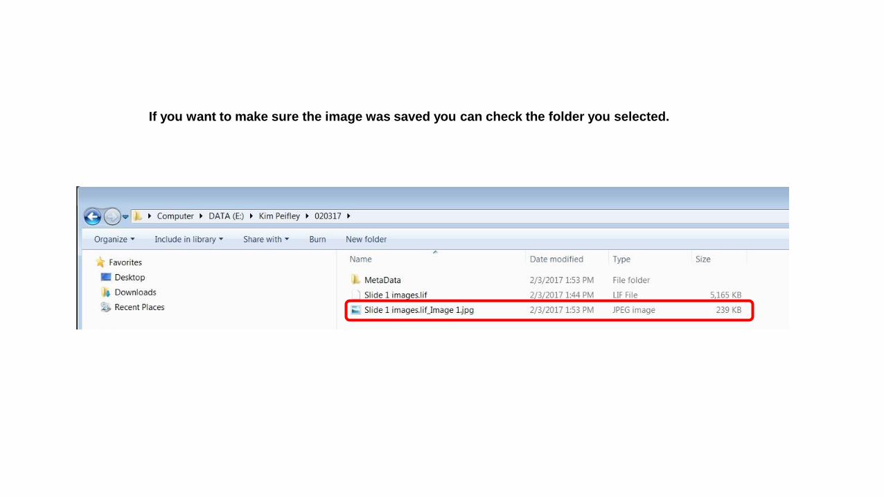
If you want to make sure the image was saved you can check the folder you selected.

This is the .jpeg image showing scale bar that was selected in Step 10.

Zoom/Crop an Image
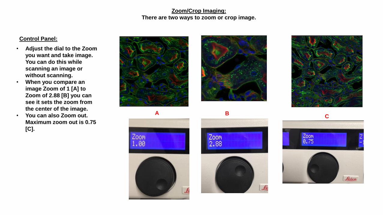
Zoom/Crop Imaging:
There are two ways to zoom or crop image.
Control Panel:
• Adjust the dial to the Zoom
you want and take image.
You can do this while
scanning an image or
without scanning.
• When you compare an
image Zoom of 1 [A] to
Zoom of 2.88 [B] you can
see it sets the zoom from
the center of the image.
• You can also Zoom out.
Maximum zoom out is 0.75
[C].
AC
B

Via the software:
1. Click on Zoom in to turn on.
2. You can now go to the image and draw a zoom window wherever you want. Green box.
3. To return to zoom of 1.0 click the reverse arrow.
1 1
2
3

Z Stack Imagingand
Maximum Intensity Projection

1. Select Sequence.
2. Click Live.
3. Using the Z position dial on the control panel,change
the focus to the point you wish to start imaging.
4. Click Begin.
5. Change focus to the point you wish to stop imaging.
6. Click End.
7. Click Stop.
1
2
4 6
7
Note: Focus has to be changed from the
control panel. If you use the focus knob on the
microscope it will not register that with the
software.

8. Select the way you want Z
stack acquired: Set number
of steps, Set Z step size
[slice size], System
optimized.
9. Z Step Size was selected to
set the slice size. Z-Step
size 1µ so there will be 15
steps.
8 9
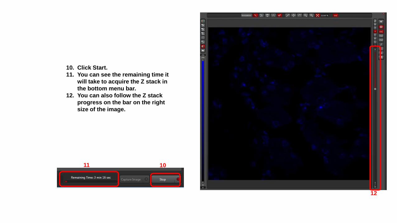
10. Click Start.
11. You can see the remaining time it
will take to acquire the Z stack in
the bottom menu bar.
12. You can also follow the Z stack
progress on the bar on the right
size of the image.
1011
12

13. When viewing your Z stack image you can move through the slices using the bar on the right.
14. To get Maximum Intensity Projection click the box below the last channel button.
15. This is your maximum intensity projection image.
13
14
15
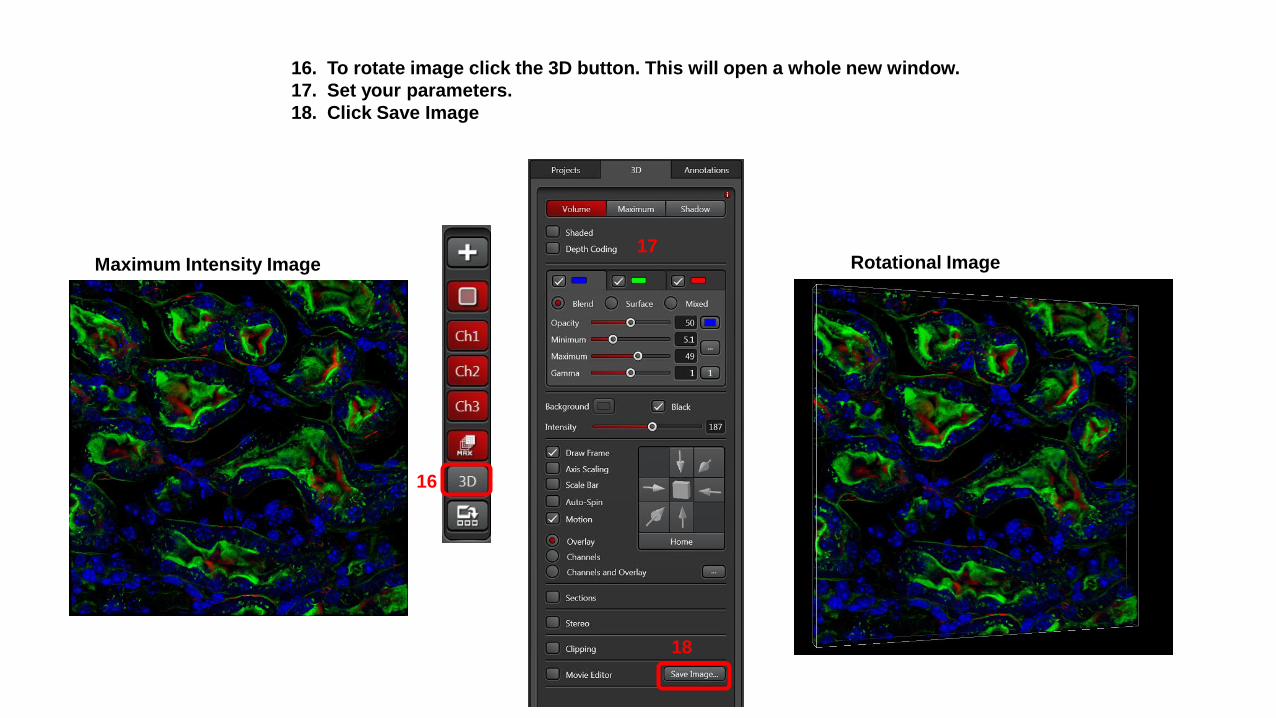
16. To rotate image click the 3D button. This will open a whole new window.
17. Set your parameters.
18. Click Save Image
Maximum Intensity Image
16
17
18
Rotational Image
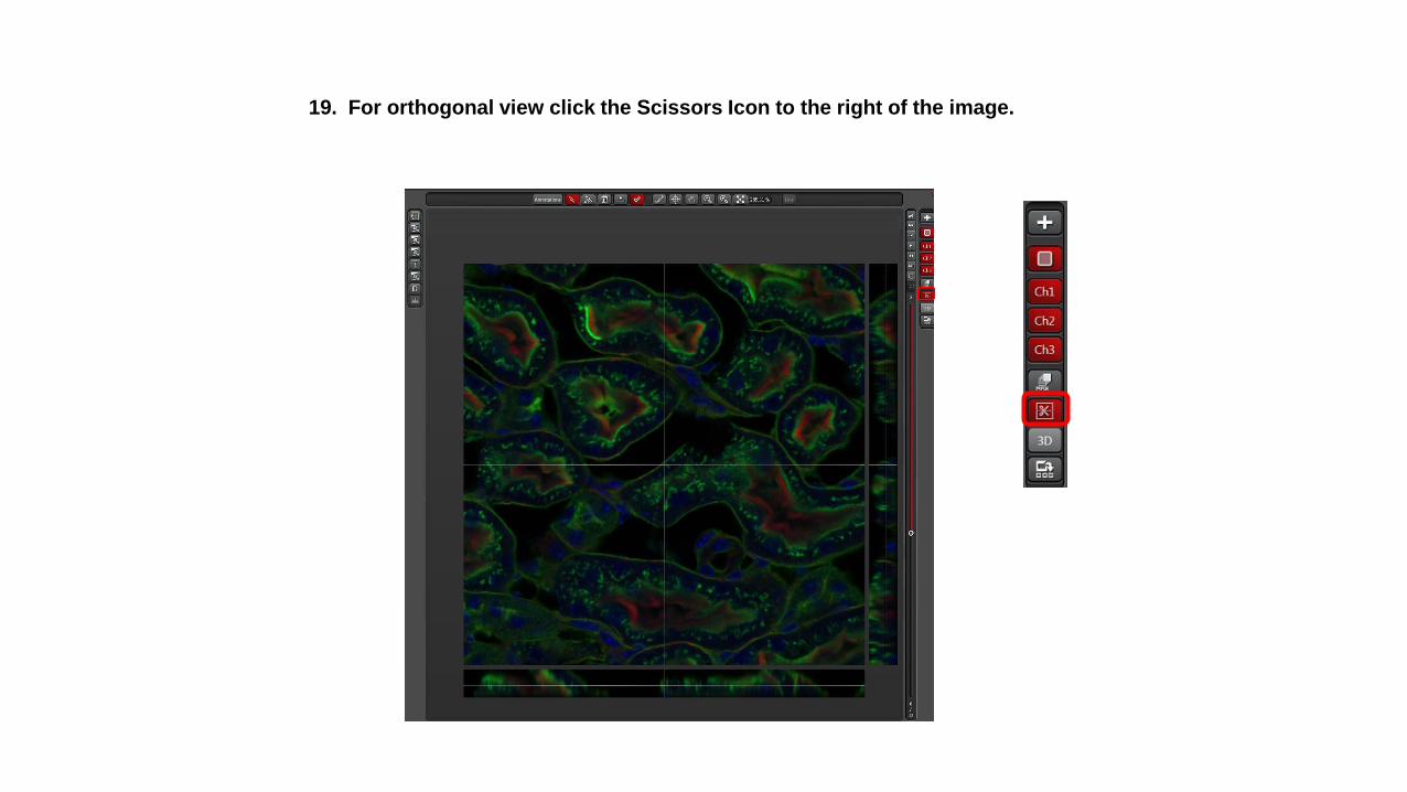
19. For orthogonal view click the Scissors Icon to the right of the image.

20. To turn off the Z stack click the Trash can icon.

Tiling

1. Set up your image like normal.
2. In Acquisition Mode window click on the icon for Define Tilescan Experiment.
3. If the Stage window does not open automatically, click the arrow next to Stage.
4. Set Field size.
5. Slick Start.
5
4
3
2

6. The remaining time to acquire
the tile is listed next to the start
button.
7. You can also follow the
progress of the tile from the
slider at the bottom of the
image window. In this image it
is now collecting tile 3 of 9.
6
7
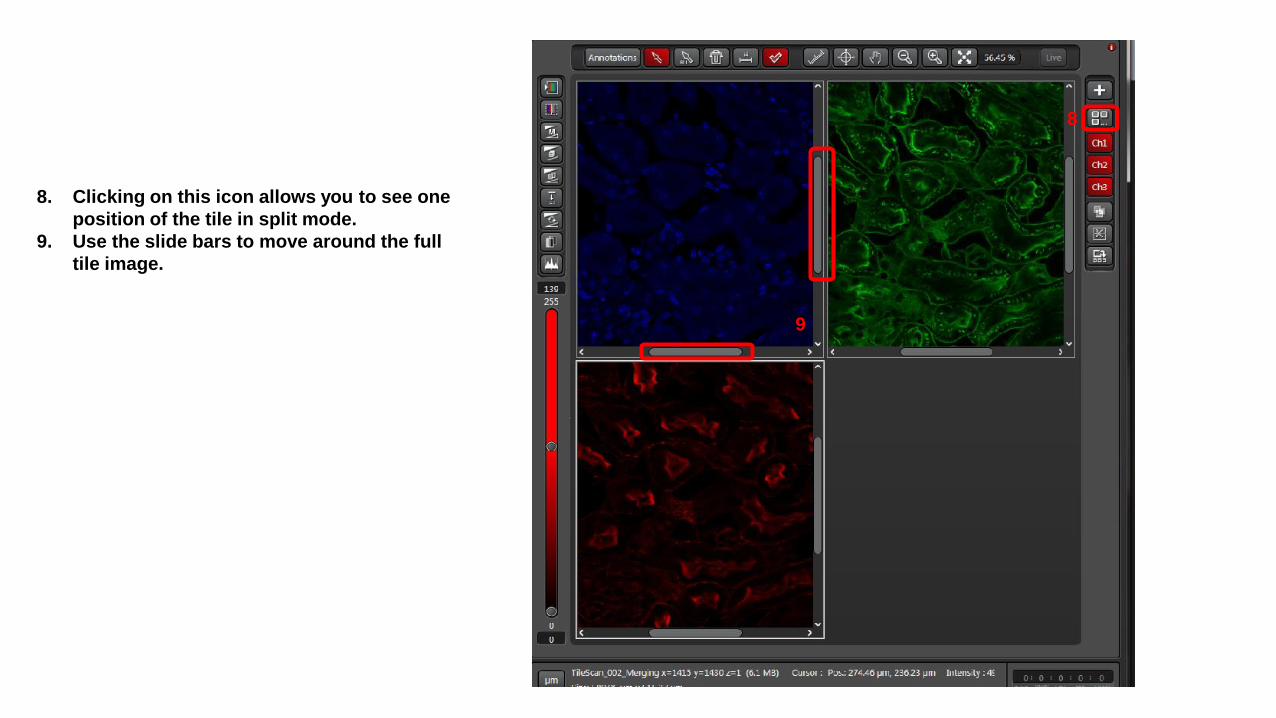
8. Clicking on this icon allows you to see one
position of the tile in split mode.
9. Use the slide bars to move around the full
tile image.
8
9
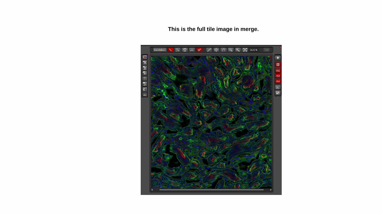
This is the full tile image in merge.
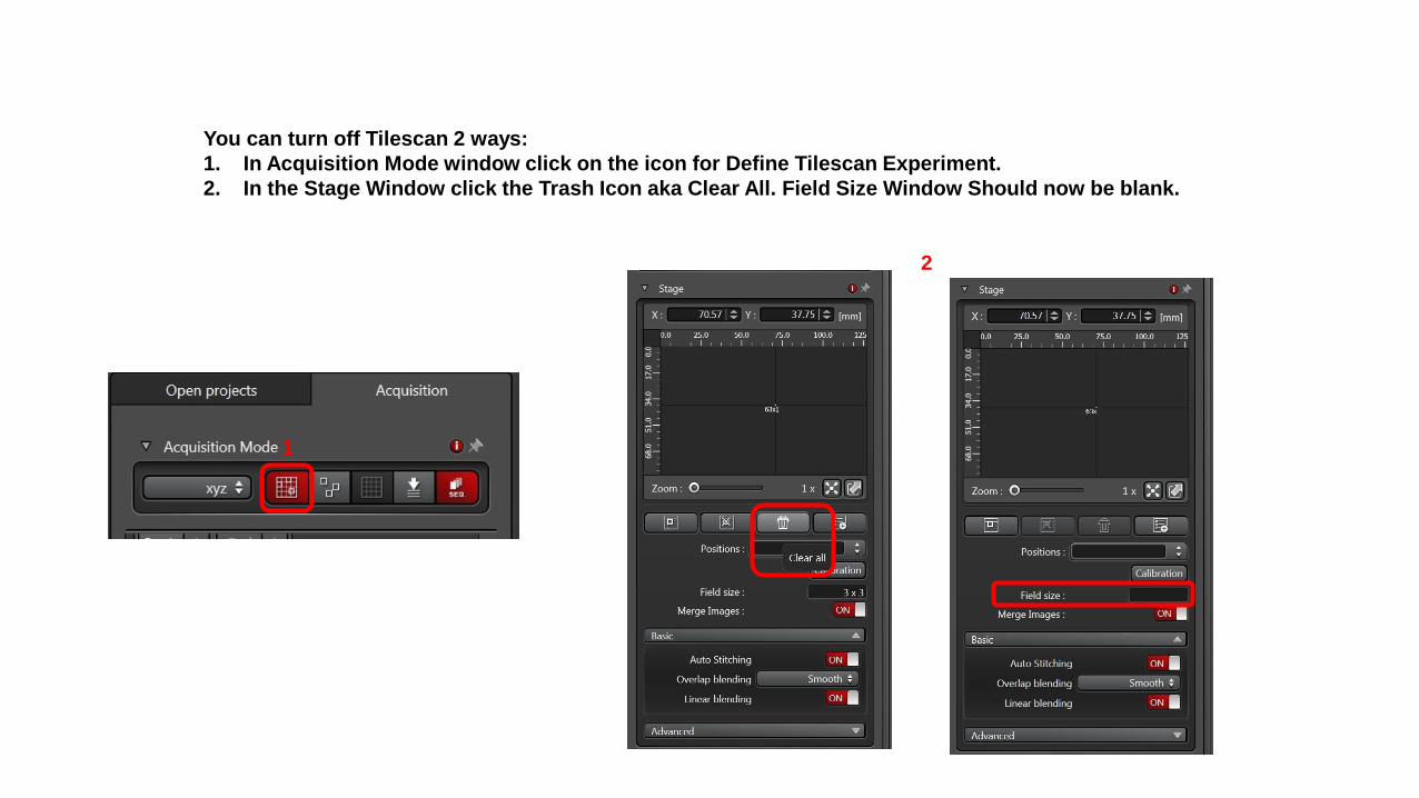
You can turn off Tilescan 2 ways:
1. In Acquisition Mode window click on the icon for Define Tilescan Experiment.
2. In the Stage Window click the Trash Icon aka Clear All. Field Size Window Should now be blank.
1
2