leica m844 leica m820 - frank's hospital workshop€¦ · manual also provides important...
TRANSCRIPT

Leica M844Leica M820User manual
10 713 294 – Version I
Living up to Life
Leica M844 – Leica M820 / Ref. 10 713 294 / Version I
Thank you for purchasing a Leica surgical microscope system.
In developing our systems, we have placed great emphasis on simple, self-explanatory operation. Nevertheless, we suggeststudying this user manual in detail in order to utilize all the benefits of your new surgical microscope.
For valuable information about Leica Microsystems products and services and the address of your nearest Leica representative,please visit our website,
www.leica-microsystems.com.
Thank you for choosing our pro ducts. We hope that you will enjoy the quality and performance of your Leica Microsystems surgical microscope.
Leica Microsystems (Schweiz) AG Surgical DivisionCH-9435 Heerbrugg
Chapter overview
1Leica M844 – Leica M820 / Ref. 10 713 294 / Version I
Introduction 3
Operating elements 8
Preparation before operation 21
Use 38
Safety notes 48
Care and maintenance 58
What to do if...? 62
Technical data 66
This manual covers the following systems:
Leica M844 F40Leica M844 F19Leica M844 C40Leica M844 CT40
Leica M820 F40Leica M820 F19Leica M820 C40Leica M820 CT40
Contents
2 Leica M844 – Leica M820 / Ref. 10 713 294 / Version I
Page
IntroductionDesign and function 4
Operating elementsStands/ceiling mounts 8Control unit 12Leica M844 and Leica M820 surgical microscopes 13Leica M844 accessories 14Leica M820 accessories 15Beam splitter, rotatable, 50/50% 15Leica M844 and Leica M820 accessories 16Foot/handswitches and handles 17Video and photo accessories for Leica M844 19Video and photo accessories for Leica M820 20
Preparation for operationPre-operation checklist 21Fitting optical accessories for Leica M844 22Fitting optical accessories for Leica M820 23Mounting beam splitter, rotatable 23Adjusting optical accessories – general information 24Adjusting optical accessories for Leica M844 25Fitting documentation accessories 26Selecting documentation accessories 27Fitting the slit lamp 28Adjusting the slit lamp 30Wide-angle observation system 32Stand settings (F40, C40, CT40) 33Stand settings (F19) 34Transport, transporting and rest positions 35Positioning at the operating table 36Sterile controls 37
UsePositioning the microscope 38Adjusting the microscope 39Touch panel 40Switching the microscope on 41 Selecting users 41Editing the user list 42Configuring users (User Settings menu) 42StepCycle 45Auto Reset 46The Maintenance menu 46The How to... menu 47The Service menu 47
Safety notesIntended use 48Directions for the person responsible for the instrument 48User qualifications 48Directions for the operator of the instrument 48Dangers of use 49
Page
Manufacturer's declaration of electromagnetic compatibility 51Signs and labels 55
Care and maintenanceMaintenance instructions 58Cleaning the touch panel 58Maintenance 58Changing fuses 59Changing bulbs 59Notes on reprocessing of sterilizable products 60Instructions 60Table: Sterilization 61
What to do if...?General 62Microscope 62Control unit 64Error messages on the control unit 64F40 stand 64C40 ceiling mount 64CT40 ceiling mount 65F19 stand 65TV, photography 65
Technical dataMicroscope 66Lamps 66Accessories 66Electrical data 67Auxiliary power socket 67Optical data 67Stands/ceiling mounts 68Ambient conditions 69Standards 69Limitations of use 69Dimensioning drawing (mm) Leica M844 F40 and Leica M820 F40 70Dimensioning drawing (mm) Leica M844 C40 and Leica M820 C40 71Dimensioning drawing (mm) for Leica M844 CT40 and Leica M820 CT40 72Dimensioning drawing (mm) for Leica M844 F19and Leica M820 F19 73

3Leica M844 – Leica M820 / Ref. 10 713 294 / Version I
Introduction
User manual
In addition to instructions for use, this user manual also provides important safety notes(see the chapter entitled, "Safety notes").Read the user manual carefully and thoroughlybefore placing the product in operation.
Product identification
The model code and serial number of your product are providedon the nameplate found on the underside of the swing arm.Write this data into your user manual and always refer to itwhen you contact us or the service workshop regarding anyquestions you may have.
Model: Serial No.:
Symbols in this user manual
The symbols used in this user manual have the following meanings:
Warning Warning regarding use hazard ornoncompliant use that can lead to seriousinjury or death.
Caution Warning regarding use hazard or noncompliant use that can lead to minorinjury, but significant article, property orenvironmental damage.
Useful information that can help the user operate the product correctly andefficiently.
Request for action; here, you are requested to take action.
➩

Introduction
4 Leica M844 – Leica M820 / Ref. 10 713 294 / Version I
1 Control unit2 Horizontal arm3 Swing arm4 XY unit5 Binocular tube6 0° assistant’s attachment (Leica M844 only)7 Handle8 Optics carrier
9 Tilt head10 Column11 Cable support12 Base13 Holding fixture for video control unit14 Handle15 Suspension device for footswitch
1 2
3
4
5
6
7
8
9
10
11
12
14
1315
Design and functionLeica M844 F40 and Leica M820 F40
Introduction
5Leica M844 – Leica M820 / Ref. 10 713 294 / Version I
1 2
3
4
5
6
7
8
9
10
11
12
14
13
15
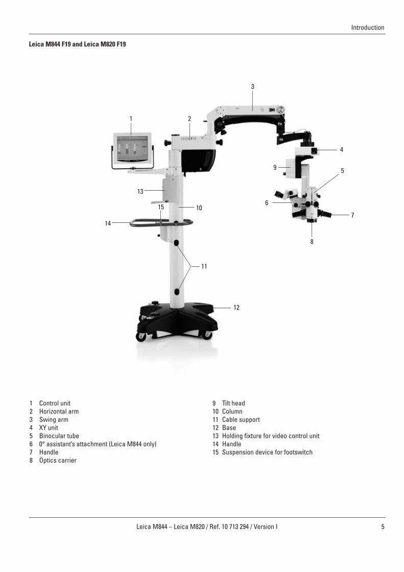
Leica M844 F19 and Leica M820 F19
1 Control unit2 Horizontal arm3 Swing arm4 XY unit5 Binocular tube6 0° assistant’s attachment (Leica M844 only)7 Handle8 Optics carrier
9 Tilt head10 Column11 Cable support12 Base13 Holding fixture for video control unit14 Handle15 Suspension device for footswitch

6 Leica M844 – Leica M820 / Ref. 10 713 294 / Version I
Introduction
Leica M844 C40 and Leica M820 C40
1 Control unit2 Horizontal arm3 Swing arm4 XY unit5 Binocular tube6 0° assistant’s attachment7 Handle8 Optics carrier
9 Tilt head13 Holding fixture for video control unit16 C40 ceiling mount17 Wall mount for control unit (optional)
4
6
7
9
21
16
13
5
8
3
17

7Leica M844 – Leica M820 / Ref. 10 713 294 / Version I
Introduction
Leica M844 CT40 and Leica M820 CT40
1 Control unit2 Horizontal arm3 Swing arm4 XY unit5 Binocular tube6 0° assistant’s attachment (Leica M844 only)7 Handle8 Optics carrier
9 Tilt head13 Holding fixture for video control unit17 Wall mount for control unit (optional)18 CT40 ceiling mount
4
6
7
9
21
18
13
5
8
3
17

8 Leica M844 – Leica M820 / Ref. 10 713 294 / Version I
Controls
Type 10448139SN 211004003Made in CH
h
Leica Microsystems (Schweiz) AGCH-9435 Heerbrugg
LEICA M844 F40100V -230V ~ 50/60Hz400VA 2x T6.3A/250V
MODEL
25 Power supply26 Fuse holder (2x 6.3 A, time-lag)27 Running-time meter for the surgical microscope28 Potential equalization socket29 Socket for remote brake release30 Auxiliary power outlet (max. output power 100 VA)
For requirements of use, see the Technical data, page 67.31 Fuse holder (1 A, time-lag)
25
3130
26 27 28 29
Caution 1Connecting unauthorized secondary devices to theauxiliary power socket can lead to damage to thesurgical microscope and to the secondary device!➩Never connect secondary devices to the auxiliary
power socket unless they conform to the specifica-tions. For requirements of use, see the Technicaldata, page 67.
23
1924
20
21
7
22
7 Handles19 Power switch20 Balancing knob21 Swing arm stop lever22 Footbrake release lever23 Footbrake24 Touch panel
Stands/ceiling mountsF40 floor stand

Controls
9Leica M844 – Leica M820 / Ref. 10 713 294 / Version I
23
19
24
20
83
85
84
7
22
85
85
27 2328 30 31 26 25
25 Power supply26 Fuse holder (2x 6.3 A, time-lag)27 Hour meter for the surgical microscope28 Potential equalization socket30 Auxiliary power outlet (max. output power 100 VA)
For requirements of use, see the Technical data, page 67.31 Fuse holder (1 A, time-lag)
Caution 1Connecting unauthorized secondary devices to theauxiliary power socket can lead to damage to thesurgical microscope and to the secondary device!➩Never connect secondary devices to the auxiliary
power socket unless they conform to the specifica-tions. For requirements of use, see the Technicaldata, page 67.
F19 floor stand
7 Handles19 Power switch20 Balancing knob22 Footbrake release lever23 Footbrake24 Touch panel83 Retaining hook (blocks swing arm)84 Retaining pin (holds retaining hook in released state)85 Articulation brakes (regulate ease of movement)

1924
25
2021
7
10 Leica M844 – Leica M820 / Ref. 10 713 294 / Version I
Controls
C40 ceiling mount
7 Handles19 Power switch20 Balancing knob21 Swing arm stop lever24 Touch panel26 No function27 Up28 Down
26
Remote control
28
27
Type 10448139SN 211004003Made in CH
h
Leica Microsystems (Schweiz) AGCH-9435 Heerbrugg
LEICA M844 C40100V -230V ~ 50/60Hz400VA 2x T6.3A/250V
MODEL
25 Power supply26 Fuse holder (2x 6.3 A, time-lag)27 Hour meter for the surgical microscope28 Potential equalization socket29 Socket for remote brake release30 Auxiliary power outlet (max. output power 100 VA)
For requirements of use, see the Technical data, page 67.31 Fuse holder (1 A, time-lag)
25
3130
26 27 28 29
Caution 1Connecting unauthorized secondary devices to theauxiliary power socket can lead to damage to thesurgical microscope and to the secondary device!➩Never connect secondary devices to the auxiliary
power socket unless they conform to the specifica-tions. For requirements of use, see the Technicaldata, page 67.

24
21
19
20
7
11Leica M844 – Leica M820 / Ref. 10 713 294 / Version I
Controls
CT40 ceiling mount
7 Handles19 Power switch20 Balancing knob21 Swing arm stop lever24 Touch panel27 Up28 Down
2827
Type 10448139SN 211004003Made in CH
h
Leica Microsystems (Schweiz) AGCH-9435 Heerbrugg
LEICA M844 CT40100V -230V ~ 50/60Hz400VA 2x T6.3A/250V
MODEL
25 Power supply26 Fuse holder (2x 6.3 A, time-lag)27 Hour meter for the surgical microscope28 Potential equalization socket29 Socket for remote brake release30 Auxiliary power outlet (max. output power 100 VA)
For requirements of use, see the Technical data, page 67.31 Fuse holder (1 A, time-lag)
25
3130
26 27 28 29
Caution 1Connecting unauthorized secondary devices to theauxiliary power socket can lead to damage to thesurgical microscope and to the secondary device!➩Never connect secondary devices to the auxiliary
power socket unless they conform to the specifi -cations. For requirements of use, see the Technicaldata, page 67.
Remote control

12 Leica M844 – Leica M820 / Ref. 10 713 294 / Version I
Controls
12
Control unitFront view
Connections
SERVICELCD
USB
DVI
RESET
VIDEOIN
IN/OUT IN/OUT EXTERN
FOOT/HAND ADF 1 1 1 2 2 2
24 Touch panel32 Brightness/contrast adjustment
Press once to adjust brightnessPress twice to adjust contrastPress three times to save adjustment and exit
33 Decrease value34 Increase value35 Video mode active LED36 Video mode/control unit (microscope) mode switch37 Control unit mode active LED
38 Service interface39 Reset button 40 USB connection41 Video input42 Internal CAN 143 Internal CAN 2
44 External CAN45 Footswitch or handswitch 146 Footswitch or handswitch 247 ADF Additional Function 148 ADF Additional Function 2
38 Service interface39 Reset button 40 USB connection41 Video input (BNC)42 Internal CAN 143 Internal CAN 2
44 External CAN45 Footswitch or handswitch 146 Footswitch or handswitch 247 ADF Additional Function 148 ADF Additional Function 2
ADF 1 and 2 are digital relay outputs that can switch24 V/2 A. During operation, use only the cables provided for CAN, video and footswitch in order to prevent malfunctions.
38 39 40
24 32 33 34 35 36 37
41 42 43 44 45 46 47
48

50
51
52
53
49 63 62
7 60
59
57
58
54
56
61
13Leica M844 – Leica M820 / Ref. 10 713 294 / Version I
Controls
13
Leica M844 and Leica M820 surgical microscopes
7 Handles49 Lamp cover opener 50 OCF – Optics Carrier Functions51 CAN bus52 Socket for external supply of slit lamp53 OttoFlex/slit lamp switch54 Rotary knob for focus fine adjustment (0° assistant’s
attachment for Leica M844 only)
56 Rotary knob for tilt drive (motorized)57 Magnification display with XY reverse display58 Focus reset59 XY reset60 Manual zoom emergency drive61 Quick-change lamp mount62 Slot for filter slide63 OttoFlexTM II iris diaphragm

14 Leica M844 – Leica M820 / Ref. 10 713 294 / Version I
Controls
14
Leica M844 accessories
A comprehensive range of accessories enables the Leica M844 surgical microscope to be matched to the requirements of the taskin hand. Your Leica representative will be pleased to help you select the appropriate accessories.
0° assistant’s attachment
Double wing
The Double Wing allows for a third observer in addition to thesurgeon and the assistant.
• the same image detail for each observer• 50 % light distribution with the assistant, still 100 % light for
the surgeon• 100 % stereopsis for all observers• ±15° horizontal rotation of binocular tubes
The M84x Double Wing (10446740) is available as anoptional accessory.
64 65
66
67
68
69
64 Documentation port65 Rotary ring for adjusting the diaphragm
Closing the diaphragm can affect the red reflex inthe video image.
66 Clamping screw for locking the binocular tube in place
Optionally, the clamping screw can be replacedwith the provided slotted screw.
67 Clamping screw for releasing the quick changer68 Focus fine adjustment knob69 Lever for turning the binocular tube by ±15°

Controls
15Leica M844 – Leica M820 / Ref. 10 713 294 / Version I
Leica M820 accessories
A comprehensive range of accessories enables the Leica M820 surgical microscope to be matched to the requirements of the taskin hand. Your Leica representative will be pleased to help you select the appropriate accessories.
Beam splitter
Attachment for second observer
Beam splitter, rotatable, 50/50%
• Allows viewing by a second person or documentation• Light distribution: 50% to the side, 50% backwards• The side exit allows a 180° rotation to the left and right• Rotate always completely to the left or right side and tighten
with clamping screw (1)
1

16 Leica M844 – Leica M820 / Ref. 10 713 294 / Version I
Controls
Leica M844 and Leica M820 accessories
6555
75
6555
75
Binocular tube 10° – 50°, low• adjustable viewing angle and height• adjustable interpupillary distance
Binocular tube, 180° variable• tilts 180°
Binocular tube 5° – 25°• adjustable viewing angle and height• adjustable interpupillary distance
Binocular tube, low• not tiltable
Binocular tube 30° – 150°• tilts 120°• adjustable interpupillary distance
Binocular tube 10° – 50° with PD• adjustable viewing angle and height• adjustable interpupillary distance
Binocular tube 10° – 50° UltraLowTM
II• with extra-low viewing height• adjustable viewing angle and height• adjustable interpupillary distance

17Leica M844 – Leica M820 / Ref. 10 713 294 / Version I
Controls
Foot/handswitches and handles
12-function footswitch, cross
12-function footswitch, long
16-function footswitch, cross
Handswitch
Handles
Standard configuration "Cataract"Here is an overview of all possible footswitches andhandswitches that you can use to control your Leica M820 andLeica M844 surgical microscopes with the standardconfiguration "Cataract".
Footswitches, handswitches and handles can beindividually assigned for each user in the configurationmenu (see page 43).

18 Leica M844 – Leica M820 / Ref. 10 713 294 / Version I
Controls
12-function footswitch, cross
12-function footswitch, long
16-function footswitch, cross
Handswitch
Handles
Standard configuration "Retina"Here is an overview of all possible footswitches andhandswitches that you can use to control your Leica M820 andLeica M844 surgical microscopes with the standardconfiguration "Retina".
Footswitches, handswitches and handles can beindividually assigned for each user in the configurationmenu (see page 43).
19Leica M844 – Leica M820 / Ref. 10 713 294 / Version I
Controls
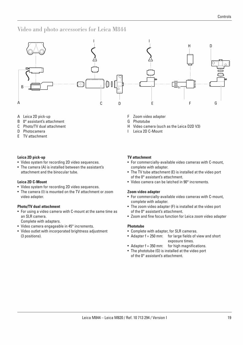
Video and photo accessories for Leica M844
Leica 2D pick-up• Video system for recording 2D video sequences.• The camera (A) is installed between the assistant’s
attachment and the binocular tube.
Leica 2D C-Mount• Video system for recording 2D video sequences.• The camera (I) is mounted on the TV attachment or zoom
video adapter.
Photo/TV dual attachment• For using a video camera with C-mount at the same time as
an SLR camera. Complete with adapters.
• Video camera engageable in 45° increments.• Video outlet with incorporated brightness adjustment
(3 positions).
TV attachment• For commercially-available video cameras with C-mount,
complete with adapter.• The TV tube attachment (E) is installed at the video port
of the 0° assistant’s attachment.• Video camera can be latched in 90° increments.
Zoom video adapter• For commercially-available video cameras with C-mount,
complete with adapter.• The zoom video adapter (F) is installed at the video port
of the 0° assistant’s attachment.• Zoom and fine focus function for Leica zoom video adapter
Phototube • Complete with adapter, for SLR cameras.• Adapter f = 250 mm: for large fields of view and short
exposure times.• Adapter f = 350 mm: for high magnifications.• The phototube (G) is installed at the video port
of the 0° assistant’s attachment.
A Leica 2D pick-upB 0° assistant’s attachmentC Photo/TV dual attachmentD PhotocameraE TV attachment
F Zoom video adapterG PhototubeH Video camera (such as the Leica D2D V3)I Leica 2D C-Mount
A
B
C FE G
IIH D
D

Controls
20 Leica M844 – Leica M820 / Ref. 10 713 294 / Version I
Video and photo accessories for Leica M820
Leica 2D pick-up• Video system for recording 2D video sequences.• The camera (A) is installed between the optics carrier and
the binocular tube.
Leica 2D C-Mount• Video system for recording 2D video sequences.• The camera (I) is mounted on the TV attachment or zoom
video adapter.
Photo/TV dual attachment• For using a video camera with C-mount at the same time as
an SLR camera. Complete with adapters.
• Video camera engageable in 45° increments.• Video outlet with incorporated brightness adjustment
(3 positions).
TV attachment• For commercially-available video cameras with C-mount,
complete with adapter.• The TV tube attachment (E) is installed at the beam splitter.• Video camera engageable in 90° increments.
Zoom video adapter• For commercially-available video cameras with C-mount,
complete with adapter.• The zoom video adapter (F) is installed at the beam splitter.• Zoom and fine focus function for Leica zoom video adapter
Phototube • Complete with adapter, for SLR cameras.• Adapter f = 250 mm: for large fields of view and short
exposure times.• Adapter f = 350 mm: for high magnifications.• The phototube (G) is installed at the beam splitter.
A Leica 2D pick-upB Beam splitter (50/50 % or 70/30 %)C Photo/TV dual attachmentD PhotocameraE TV attachment
F Zoom video adapterG PhototubeH Video camera (such as the Leica D2D V3)I Leica 2D C-Mount
A B C F GE
IIH
D
D
21Leica M844 – Leica M820 / Ref. 10 713 294 / Version I
Preparation for operation
Checklist: Before the operationCleaning the optical accessories➩Select the eyepieces, objective and the documentation
accessories (if used) and check them for cleanliness.➩Remove dust and dirt (see page 58).
Checking accessories➩Lock the swing arm.➩Outfit the microscope with all accessories for use
(see pages 22-24).➩Turn 0°-assistant’s attachment to the desired side
(Leica M844, see page 25) or install attachment for secondobserver on the desired side (Leica M820).
Balancing➩Release and balance swing arm
(see pages 33 and 34).
Function check➩Switch the microscope on.
Warning 1Motors return to their home positions➩Before switching on the microscope, ensure that the
travel paths of the X- and Y-axes and the focus motorare free of obstructions.
➩Check the Main Light 1, Main Light 2 and OttoFlexTM IIilluminators. Replace defective bulbs before the operation begins.
➩Test all handswitch and footswitch functions.➩Check the brake function using both the handles and
the remote brake release (see page 33).
Positioning at the OP table➩Position the surgical microscope at the operating table as
desired and secure the brakes on the floor stand. (see page 36).
Checking tube settings➩Check the tube and eyepiece setting for the selected user
(see page 24).➩Treat the eyepieces with an antifogging compound if
necessary.
Sterility➩Fit sterile components and sterile drape if used
(see page 59).
Warning 2Danger of fatal electric shock➩Operate the system only with all equipment in its
proper position (all covers fitted, doors closed).

22 Leica M844 – Leica M820 / Ref. 10 713 294 / Version I
Preparation for operation
Fitting optical accessories for Leica M844Warning 3Risk of injury from downward movement of surgicalmicroscope!➩Complete all preparations and adjustments to the
stand before the operation.➩Never balance or re-equip the instrument over the
field of operation.➩Before re-equipping, always lock the swing arm.➩After re-equipping, always rebalance the microscope
on the swing arm.➩Do not release the brakes when the instrument is in an
unbalanced state.➩Before re-equipping during the operation, first swing
the microscope away from the operating field.
Take care that the articulation brakes are tightenedand the swing arm is blocked before you mount accessories to your Leica M844 (see page 34).
Fitting objectives➩Screw the objectives onto the microscope (right-hand
threading).
Fitting the 0° assistant’s attachment
The 0° assistant’s attachment must be directly
attached to the optics carrier.
➩Unscrew the clamping screw as far as necessary using ascrewdriver.
➩Insert the 0° assistant’s attachment into the dovetail ring.➩While holding the 0° assistant’s attachment in place, tighten
the clamping screw.
Do not use a beam splitter in addition to the 0° assistant’s attachment.
Fitting the tube➩Release the clamping screw on the dovetail ring of the 0°
assistant’s attachment and remove the black protective cover.➩Carefully insert the second observer tube and tighten the
clamping screw.
Fitting eyepieces➩Fasten the eyepieces with the fixing rings in the tubes.
Fitting the Double Wing
We recommend mounting the longer arm of the DoubleWing on the side of the focus housing in order to achieve optimal ergonomic conditions.
➩Screw out the clamping screw until it stops by means of thescrewdriver.
➩Insert the attachment of theDouble Wing into the dovetailring so that the arrow ispositioned exactly over theclamping screw.
➩Hold the Double Wing firmly and tighten the clamping screw.
When the combination with the Double Wing is used we recommend that the main surgeon uses theUltraLowTM II binocular tube. The UltraLowTM IIbinocular tube offers better ergonomic conditions.
Clamping screw

Preparation for operation
23Leica M844 – Leica M820 / Ref. 10 713 294 / Version I
Fitting optical accessories for Leica M820Warning 3Risk of injury from downward movement of surgicalmicroscope!➩Complete all preparations and adjustments to the
stand before the operation.➩Never balance or re-equip the instrument over the
field of operation.➩Before re-equipping, always lock the swing arm.➩After re-equipping, always rebalance the microscope
on the swing arm.➩Do not release the brakes when the instrument is in an
unbalanced state.➩Before re-equipping during the operation, first swing
the microscope away from the operating field.
Take care that the articulation brakes are tightenedand the swing arm is blocked before you mount accessories to your Leica M820 F19 (see page 34).
Fitting objectives
➩Screw the objectives onto the microscope(right-hand threading).
Fitting the beam splitter
➩Unscrew the clamping screw to the stop.➩Insert the beam splitter into the dovetail ring and turn slightly
to the side until the positioning screw engages the guide.
1
Fitting the attachment for second observer
➩Install the attachment for second observer to the beamsplitter.
➩Align the attachment for second observer as required.➩Fit the tube and set up the image with the knurled ring.
Fitting the tube➩Release the clamping screw on the beam splitter and
attachment for second observer and remove the protectivecover.
➩Carefully insert the tube and tighten the clamping screw.
Fitting eyepieces➩Affix the eyepieces with the fixing rings in the tubes.
Mounting beam splitter, rotatable
• Remove the clamping screw (1)• Mount the grub screw (1)• Place beam splitter, rotatable into the
dovetail ring from above• Tighten the grub screw (1)
1
1Knurled ring
Tube➔
Preparation for operation
24 Leica M844 – Leica M820 / Ref. 10 713 294 / Version I
6555
75
Interpupillary distance scale
Setting wheel
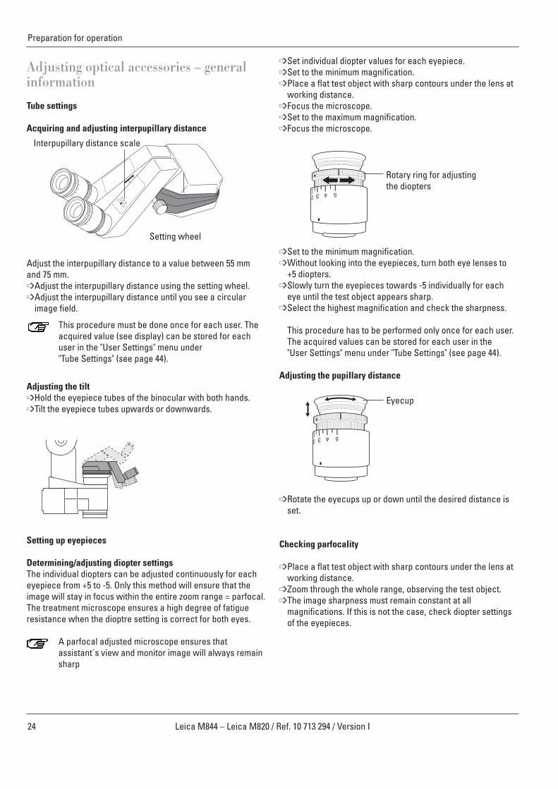
Adjusting optical accessories – generalinformation
Tube settings
Acquiring and adjusting interpupillary distance
Adjust the interpupillary distance to a value between 55 mmand 75 mm.➩Adjust the interpupillary distance using the setting wheel.➩Adjust the interpupillary distance until you see a circular
image field.
This procedure must be done once for each user. Theacquired value (see display) can be stored for eachuser in the "User Settings" menu under "Tube Settings" (see page 44).
Adjusting the tilt➩Hold the eyepiece tubes of the binocular with both hands.➩Tilt the eyepiece tubes upwards or downwards.
Setting up eyepieces
Determining/adjusting diopter settingsThe individual diopters can be adjusted continuously for eacheyepiece from +5 to -5. Only this method will ensure that theimage will stay in focus within the entire zoom range = parfocal.The treatment microscope ensures a high degree of fatigueresistance when the dioptre setting is correct for both eyes.
A parfocal adjusted microscope ensures thatassistant´s view and monitor image will always remainsharp
➩Set individual diopter values for each eyepiece.➩Set to the minimum magnification.➩Place a flat test object with sharp contours under the lens at
working distance.➩Focus the microscope.➩Set to the maximum magnification.➩Focus the microscope.
➩Set to the minimum magnification.➩Without looking into the eyepieces, turn both eye lenses to
+5 diopters.➩Slowly turn the eyepieces towards -5 individually for each
eye until the test object appears sharp.➩Select the highest magnification and check the sharpness.
This procedure has to be performed only once for each user.The acquired values can be stored for each user in the"User Settings" menu under "Tube Settings" (see page 44).
Adjusting the pupillary distance
➩Rotate the eyecups up or down until the desired distance isset.
Checking parfocality
➩Place a flat test object with sharp contours under the lens atworking distance.
➩Zoom through the whole range, observing the test object.➩The image sharpness must remain constant at all
magnifications. If this is not the case, check diopter settingsof the eyepieces.
Rotary ring for adjusting the diopters
Eyecup
25Leica M844 – Leica M820 / Ref. 10 713 294 / Version I
Preparation for operation
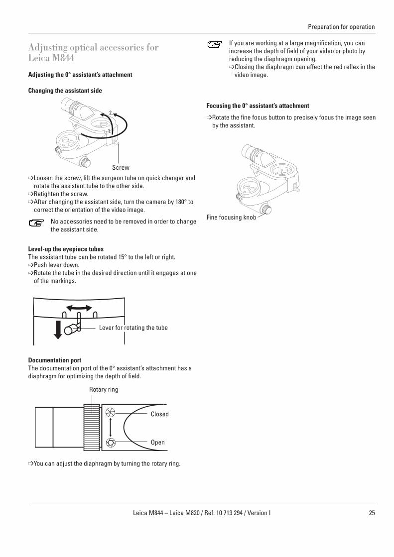
Adjusting optical accessories forLeica M844
Adjusting the 0° assistant’s attachment
Changing the assistant side
➩Loosen the screw, lift the surgeon tube on quick changer androtate the assistant tube to the other side.
➩Retighten the screw.➩After changing the assistant side, turn the camera by 180° to
correct the orientation of the video image.
No accessories need to be removed in order to changethe assistant side.
Level-up the eyepiece tubesThe assistant tube can be rotated 15° to the left or right.➩Push lever down.➩Rotate the tube in the desired direction until it engages at one
of the markings.
Documentation portThe documentation port of the 0° assistant’s attachment has adiaphragm for optimizing the depth of field.
➩You can adjust the diaphragm by turning the rotary ring.
If you are working at a large magnification, you canincrease the depth of field of your video or photo byreducing the diaphragm opening.➩Closing the diaphragm can affect the red reflex in the
video image.
Focusing the 0° assistant’s attachment
➩Rotate the fine focus button to precisely focus the image seenby the assistant.
1.
2.
Rotary ring
Closed
Open
Screw
Fine focusing knob
Lever for rotating the tube

26 Leica M844 – Leica M820 / Ref. 10 713 294 / Version I
Preparation for operation
Fitting documentation accessories
Fitting the Leica 2D➩See Leica 2D User Manual (10708979).
Fitting the photo/TV dual attachment➩Fit dual attachment on the assistant side of the
0°-assistant’s attachment (Leica M844) or on the beamsplitter (Leica M820).
➩Equip the video camera with the TV objective and insert intothe dual attachment.
➩Tighten the clamping screw.➩Equip the photo camera with the camera adapter. Screw the
photo objective to the camera adapter. Fit the camera to thedual attachment.
➩Tighten the clamping screw.➩Loosen the clamping screw and engage the video camera
until it latches in one of the 45° steps depending on the avail-able space.
➩Tighten the clamping screw.
The object image at the camera output is laterallyreversed!
Using the dial, the brightness of the video can be adjust-ed to 30%, 50% or 100%. One of these filters can beswitched with the 8% filter provided. To do so, removethe camera and change the filter in the TV output.
TV attachment / zoom video adapter➩Fasten the TV attachment to the video port of the
0° assistant’s attachment (Leica M844) or the beamsplitter (Leica M820).
➩Screw the adapter to the camera using the C-mount.➩Insert the camera with the adapter into the TV attachment
and tighten the clamping screw.
90° click-stop (TV attachment only):➩Loosen the clamping screw.➩Latch the camera at one of the 90° steps in accordance with
the space available and tighten the clamping screw.
Adjust parfocality of the zoom video adapter.➩Select the highest magnification.➩Place a flat test object with sharp contours under the
objective.➩Look through the eyepieces and focus the
microscope.➩Select the lowest magnification.➩Set the maximum magnification (f=100) on the zoom
video adapter.➩Focus the monitor image on the zoom video adapter.➩Set the desired image magnification at the zoom
video adapter.
Fitting the phototube
➩Fasten the phototube to the video port of the 0°-assistant’s attachment (Leica M844) or to the beam splitter(Leica M820).
➩Secure the camera adapter to the SLR camera.➩Connect the f = 250 mm or f = 350 mm adapter to the camera
adapter.➩Secure the camera, complete with adapter, in the phototube.
Tighten the clamping screw.
Clamping screw
Camera adapter
Camera
Focusing knob
Adjusting the magnification
Adapter
Phototube
Clamping screw
Video camera (such as the Leica D2D V3)
C-mount adapter
TV attachmentClamping screw
Video camera (such as the Leica D2D V3)

27Leica M844 – Leica M820 / Ref. 10 713 294 / Version I
Preparation for operation
250 mmPhoto/TV dual attachment
35 mm
DigitalPhotoCamera
350 mm
Selecting documentation accessories
Field of view
Monitor/image
70mm
1“
2/3 “
1/2 “
1/3 “
1/4 “
107mm100mm85mm60mm55mm35mm
PhotoTV dualattachment
TV attachment
TVattachment
TVattachment
PhotoTV dualattachment
Zoom video adapter Zoom video Adapter
28 Leica M844 – Leica M820 / Ref. 10 713 294 / Version I
Preparation for operation
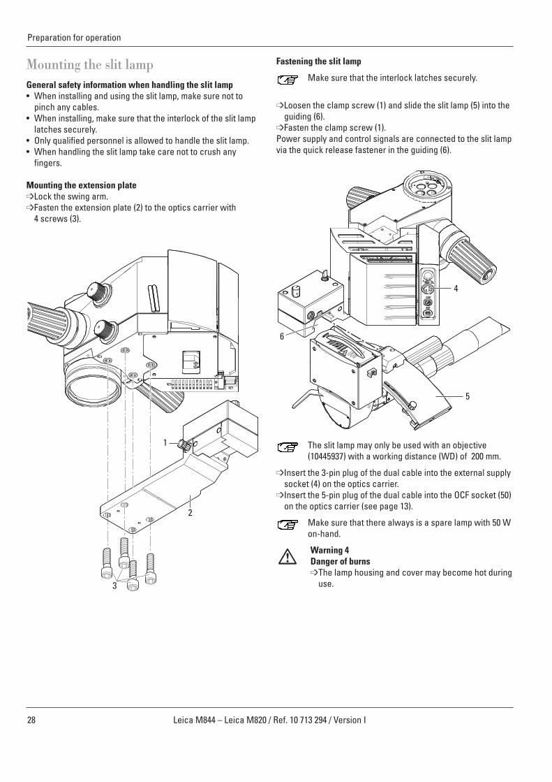
Mounting the slit lampGeneral safety information when handling the slit lamp• When installing and using the slit lamp, make sure not to
pinch any cables.• When installing, make sure that the interlock of the slit lamp
latches securely.• Only qualified personnel is allowed to handle the slit lamp.• When handling the slit lamp take care not to crush any
fingers.
Mounting the extension plate➩Lock the swing arm.➩Fasten the extension plate (2) to the optics carrier with
4 screws (3).
2
3
1
Fastening the slit lamp
Make sure that the interlock latches securely.
➩Loosen the clamp screw (1) and slide the slit lamp (5) into theguiding (6).
➩Fasten the clamp screw (1).Power supply and control signals are connected to the slit lampvia the quick release fastener in the guiding (6).
The slit lamp may only be used with an objective(10445937) with a working distance (WD) of 200 mm.
➩Insert the 3-pin plug of the dual cable into the external supplysocket (4) on the optics carrier.
➩Insert the 5-pin plug of the dual cable into the OCF socket (50)on the optics carrier (see page 13).
Make sure that there always is a spare lamp with 50 Won-hand.
Warning 4Danger of burns➩The lamp housing and cover may become hot during
use.
6
5
4
29Leica M844 – Leica M820 / Ref. 10 713 294 / Version I
Preparation for operation
Emergency operationIf the motor of the prism is inoperative, the prism may be movedby hand.
Dismounting the slit lamp
When dismounting the slit lamp, make sure that bothstoppers are in the bottom position.
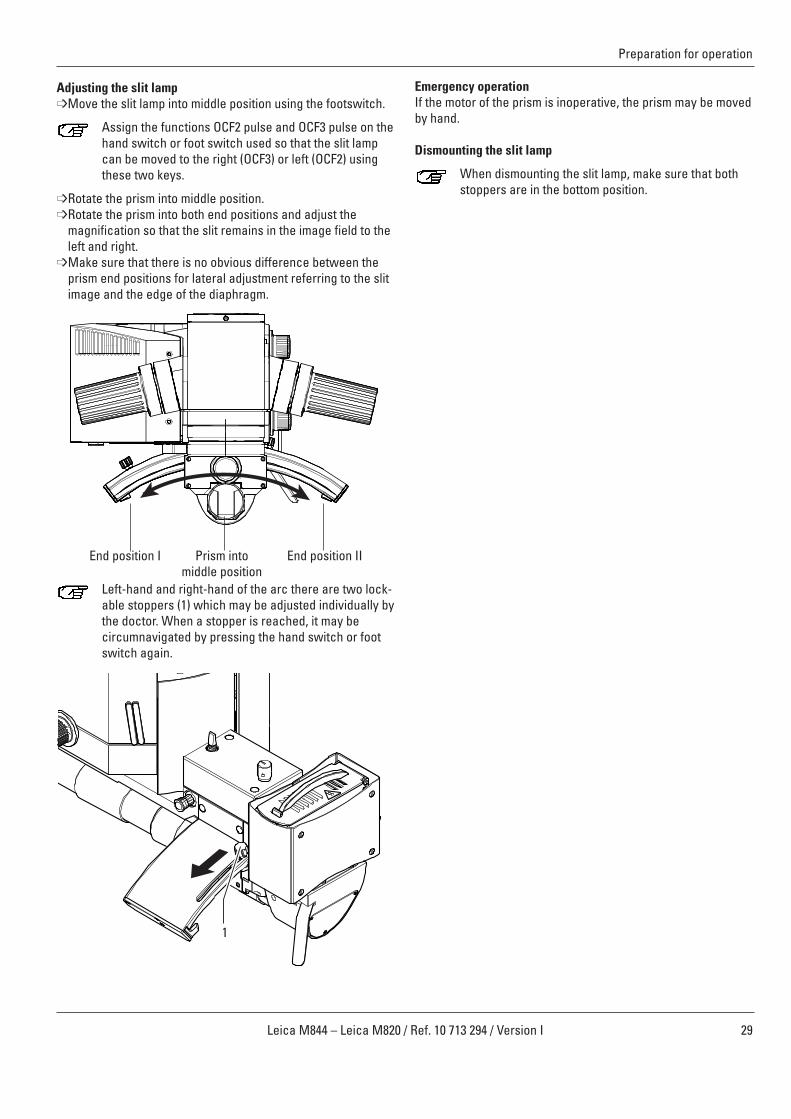
Adjusting the slit lamp➩Move the slit lamp into middle position using the footswitch.
Assign the functions OCF2 pulse and OCF3 pulse on thehand switch or foot switch used so that the slit lampcan be moved to the right (OCF3) or left (OCF2) usingthese two keys.
➩Rotate the prism into middle position.➩Rotate the prism into both end positions and adjust the
magnification so that the slit remains in the image field to theleft and right.
➩Make sure that there is no obvious difference between theprism end positions for lateral adjustment referring to the slitimage and the edge of the diaphragm.
Left-hand and right-hand of the arc there are two lock-able stoppers (1) which may be adjusted individually bythe doctor. When a stopper is reached, it may becircumnavigated by pressing the hand switch or footswitch again.
1
End position I End position IIPrism intomiddle position
30 Leica M844 – Leica M820 / Ref. 10 713 294 / Version I
Adjusting the slit lampCaution 2Danger of crushing due to moving parts!The parts of the slit lamp that are moved by motorsmay crush fingers or the hand when used improperly.➩When handling the slit lamp, take care not to crush
any fingers.
➩For activation of the slit lamp, use the Slitlamp/OttoFlexswitch (53) on the optics carrier (see page 13).
Adjusting the brightness of the slit lampWarning 5Danger of eye injuries!The light source of the slit lamp might be too brightfor the patient.➩Dim the slit lamp before switching it on.➩Slowly increase the brightness until the image is
illuminated optimally for the operating doctor.
➩To switch the slit lamp on or off, use the OttoFlex ON/OFFfunction on the hand switch or foot switch.
➩To adjust brightness, press the „+“ or „–“ -button, or directlypress the brightness bar of the slit lamp.
Clicking the „+“ or „–“ -button changes the brightnessvalue in increments of 1. Holding the mouse buttondown changes the value in increments of 5.
➩Brightness of the slit lamp may also be changed by using aconnected hand switch or foot switch with the OttoFlex +/–function.
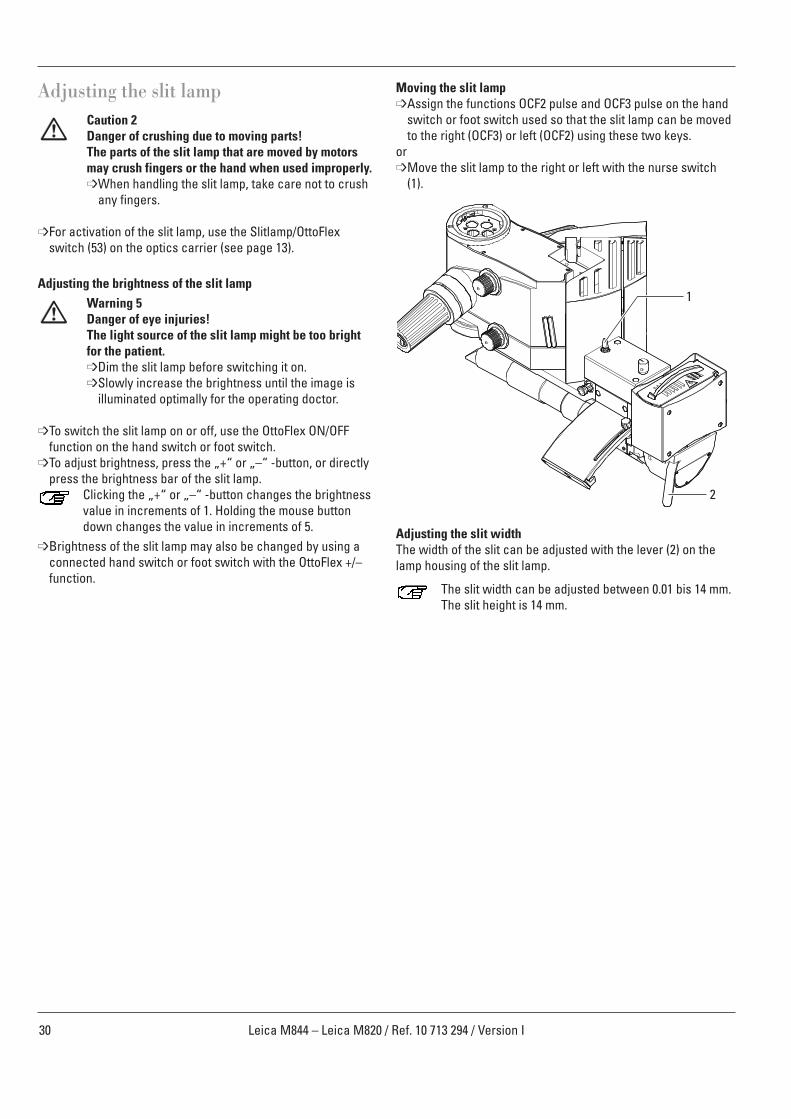
Moving the slit lamp➩Assign the functions OCF2 pulse and OCF3 pulse on the hand
switch or foot switch used so that the slit lamp can be movedto the right (OCF3) or left (OCF2) using these two keys.
or➩Move the slit lamp to the right or left with the nurse switch
(1).
Adjusting the slit widthThe width of the slit can be adjusted with the lever (2) on thelamp housing of the slit lamp.
The slit width can be adjusted between 0.01 bis 14 mm.The slit height is 14 mm.
1
2

31Leica M844 – Leica M820 / Ref. 10 713 294 / Version I
Connecting the BIOM to the slit lamp
➩Insert the plug of the BIOM into the socket (2) on the slit lamp.➩Use the rotary switch (1) to change between BIOM and slit
lamp.
Sterile covers for the slit tube The slit tube of the slit lamp can be protected by sterile cover(3), the lever for adjusting the slit width can be protected bysterile cover (4).
21
3
4
Phototoxic damage to the retina during eye surgery
Warning 6Damage to the eyes due to prolonged exposure!The light of the instrument may be harmful. Risk of eyedamage increases with the duration of exposure.➩Do not exceed the exposure limits.
An exposure to this instrument for longer than 2.8 minat maximum output power exceeds the exposure limits.
The following table shows the allowed surgery durations andtheir possible extension when reducing the slit width:
slit width [mm] time [s]>6 1645 1814 2333 2702 4551 909
➩Protect the patient by:• short illumination times• low brightness level• switching the light off when interrupting the surgeryIt is recommended to adjust the brightness to the minimum nec-essary for the surgery.Babies or aphacia patients, where the eye lens has not beenexchanged by an artificial lens with UV-protection, infants andpatients with eye sickness are at a greater risk.There also is a greater risk, if the patient was exposed to thesame or any other ophthamological instrument using a brightvisible light source within the previous 24 hours.This applies especially, if the eye was examined by retinaphotography.Decisions about brightness must be made case by case.In any case the surgeon has to make a risk-benefit analysisconcerning the applicable brightness.Despite any effort to minimize the risk of damage to the retinaby the surgical microscope, injuries still might occur.Photochemical damage to the retina is one possiblecomplication due to the necessity of using bright light to visual-ize eye structures during difficult ophthamologic processes.
32 Leica M844 – Leica M820 / Ref. 10 713 294 / Version I
Preparation for operation
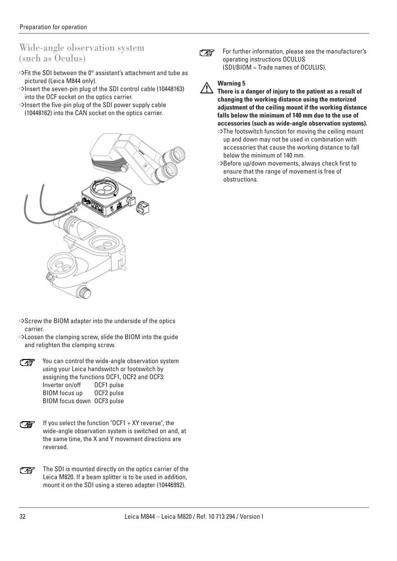
For further information, please see the manufacturer’soperating instructions OCULUS(SDI/BIOM = Trade names of OCULUS).
Warning 5There is a danger of injury to the patient as a result ofchanging the working distance using the motorizedadjustment of the ceiling mount if the working distancefalls below the minimum of 140 mm due to the use ofaccessories (such as wide-angle observation systems).➩The footswitch function for moving the ceiling mount
up and down may not be used in combination withaccessories that cause the working distance to fallbelow the minimum of 140 mm.
➩Before up/down movements, always check first toensure that the range of movement is free of obstructions.
Wide-angle observation system (such as Oculus) ➩Fit the SDI between the 0° assistant’s attachment and tube as
pictured (Leica M844 only).➩Insert the seven-pin plug of the SDI control cable (10448163)
into the OCF socket on the optics carrier.➩Insert the five-pin plug of the SDI power supply cable
(10448162) into the CAN socket on the optics carrier.
➩Screw the BIOM adapter into the underside of the optics carrier.
➩Loosen the clamping screw, slide the BIOM into the guideand retighten the clamping screw.
You can control the wide-angle observation systemusing your Leica handswitch or footswitch byassigning the functions OCF1, OCF2 and OCF3:Inverter on/off OCF1 pulse BIOM focus up OCF2 pulseBIOM focus down OCF3 pulse
If you select the function "OCF1 + XY reverse", thewide-angle observation system is switched on and, atthe same time, the X and Y movement directions arereversed.
The SDI is mounted directly on the optics carrier of theLeica M820. If a beam splitter is to be used in addition,mount it on the SDI using a stereo adapter (10446992).
33Leica M844 – Leica M820 / Ref. 10 713 294 / Version I
Preparation for operation
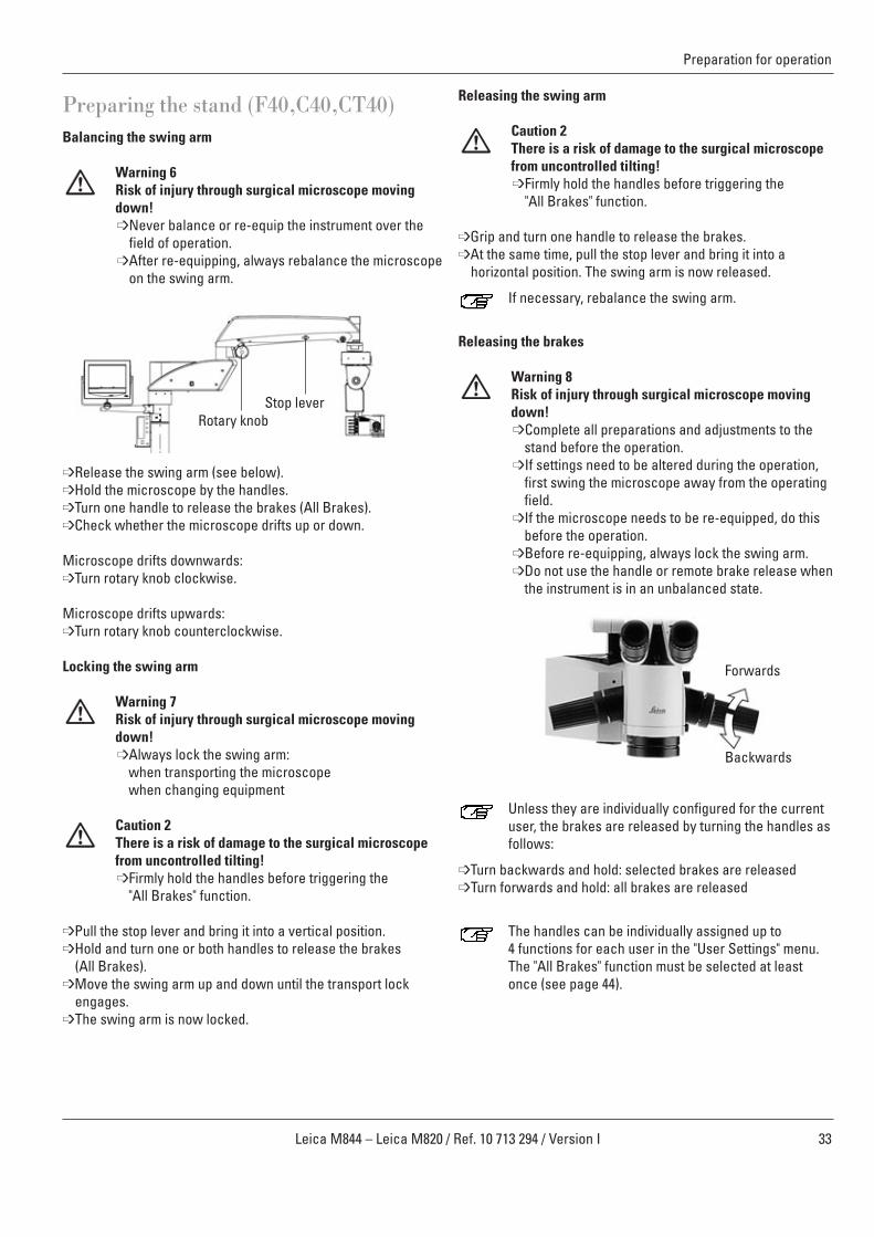
Preparing the stand (F40,C40,CT40)Balancing the swing arm
Warning 6Risk of injury through surgical microscope movingdown!➩Never balance or re-equip the instrument over the
field of operation.➩After re-equipping, always rebalance the microscope
on the swing arm.
➩Release the swing arm (see below).➩Hold the microscope by the handles.➩Turn one handle to release the brakes (All Brakes).➩Check whether the microscope drifts up or down.
Microscope drifts downwards:➩Turn rotary knob clockwise.
Microscope drifts upwards:➩Turn rotary knob counterclockwise.
Locking the swing arm
Warning 7Risk of injury through surgical microscope movingdown!➩Always lock the swing arm:
when transporting the microscope when changing equipment
Caution 2There is a risk of damage to the surgical microscopefrom uncontrolled tilting!➩Firmly hold the handles before triggering the
"All Brakes" function.
➩Pull the stop lever and bring it into a vertical position.➩Hold and turn one or both handles to release the brakes
(All Brakes).➩Move the swing arm up and down until the transport lock
engages.➩The swing arm is now locked.
Stop leverRotary knob
Releasing the swing arm
Caution 2There is a risk of damage to the surgical microscopefrom uncontrolled tilting!➩Firmly hold the handles before triggering the
"All Brakes" function.
➩Grip and turn one handle to release the brakes.➩At the same time, pull the stop lever and bring it into a
horizontal position. The swing arm is now released.
If necessary, rebalance the swing arm.
Releasing the brakes
Warning 8Risk of injury through surgical microscope movingdown!➩Complete all preparations and adjustments to the
stand before the operation.➩If settings need to be altered during the operation,
first swing the microscope away from the operatingfield.
➩If the microscope needs to be re-equipped, do thisbefore the operation.
➩Before re-equipping, always lock the swing arm.➩Do not use the handle or remote brake release when
the instrument is in an unbalanced state.
Unless they are individually configured for the currentuser, the brakes are released by turning the handles asfollows:
➩Turn backwards and hold: selected brakes are released➩Turn forwards and hold: all brakes are released
The handles can be individually assigned up to 4 functions for each user in the "User Settings" menu.The "All Brakes" function must be selected at leastonce (see page 44).
Forwards
Backwards
34 Leica M844 – Leica M820 / Ref. 10 713 294 / Version I
Preparation for operation
REM
OTE
BRAK
E
REL
EASE
UpCeiling mount
C40 remotecontrolC40 remotecontrol
Down
Up Down
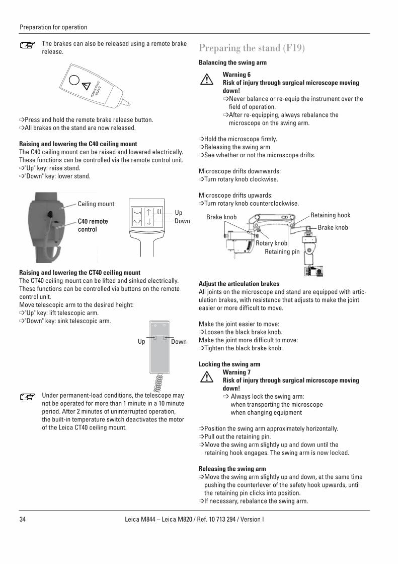
The brakes can also be released using a remote brakerelease.
➩Press and hold the remote brake release button.➩All brakes on the stand are now released.
Raising and lowering the C40 ceiling mountThe C40 ceiling mount can be raised and lowered electrically.These functions can be controlled via the remote control unit.➩"Up" key: raise stand.➩"Down" key: lower stand.
Raising and lowering the CT40 ceiling mountThe CT40 ceiling mount can be lifted and sinked electrically.These functions can be controlled via buttons on the remotecontrol unit.Move telescopic arm to the desired height:➩"Up" key: lift telescopic arm.➩"Down" key: sink telescopic arm.
Under permanent-load conditions, the telescope maynot be operated for more than 1 minute in a 10 minuteperiod. After 2 minutes of uninterrupted operation,the built-in temperature switch deactivates the motorof the Leica CT40 ceiling mount.
Preparing the stand (F19)Balancing the swing arm
Warning 6Risk of injury through surgical microscope movingdown!➩Never balance or re-equip the instrument over the
field of operation.➩After re-equipping, always rebalance the
microscope on the swing arm.
➩Hold the microscope firmly.➩Releasing the swing arm➩See whether or not the microscope drifts.
Microscope drifts downwards:➩Turn rotary knob clockwise.
Microscope drifts upwards:➩Turn rotary knob counterclockwise.
Adjust the articulation brakesAll joints on the microscope and stand are equipped with artic-ulation brakes, with resistance that adjusts to make the jointeasier or more difficult to move.
Make the joint easier to move: ➩Loosen the black brake knob.Make the joint more difficult to move: ➩Tighten the black brake knob.
Locking the swing armWarning 7Risk of injury through surgical microscope movingdown!➩ Always lock the swing arm:
when transporting the microscope when changing equipment
➩Position the swing arm approximately horizontally.➩Pull out the retaining pin.➩Move the swing arm slightly up and down until the
retaining hook engages. The swing arm is now locked.
Releasing the swing arm➩Move the swing arm slightly up and down, at the same time
pushing the counterlever of the safety hook upwards, untilthe retaining pin clicks into position.
➩If necessary, rebalance the swing arm.
Retaining hook
Retaining pin
Brake knob
Brake knob
Rotary knob
35Leica M844 – Leica M820 / Ref. 10 713 294 / Version I
Preparation for operation
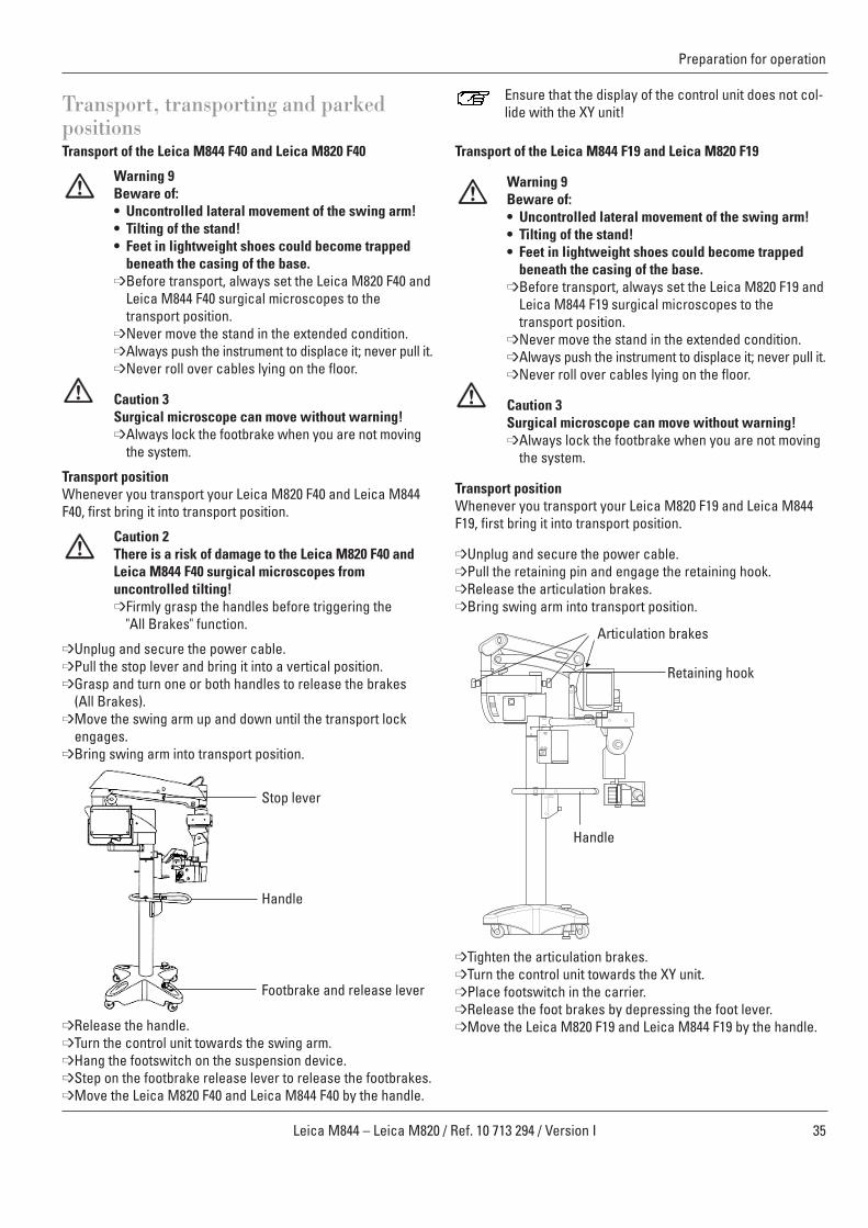
Transport, transporting and parked positionsTransport of the Leica M844 F40 and Leica M820 F40
Warning 9Beware of: • Uncontrolled lateral movement of the swing arm!• Tilting of the stand!• Feet in lightweight shoes could become trapped
beneath the casing of the base.➩Before transport, always set the Leica M820 F40 and
Leica M844 F40 surgical microscopes to thetransport position.
➩Never move the stand in the extended condition.➩Always push the instrument to displace it; never pull it.➩Never roll over cables lying on the floor.
Caution 3Surgical microscope can move without warning!➩Always lock the footbrake when you are not moving
the system.
Transport position Whenever you transport your Leica M820 F40 and Leica M844F40, first bring it into transport position.
Caution 2There is a risk of damage to the Leica M820 F40 andLeica M844 F40 surgical microscopes fromuncontrolled tilting!➩Firmly grasp the handles before triggering the
"All Brakes" function.
➩Unplug and secure the power cable. ➩Pull the stop lever and bring it into a vertical position.➩Grasp and turn one or both handles to release the brakes
(All Brakes).➩Move the swing arm up and down until the transport lock
engages.➩Bring swing arm into transport position.
➩Release the handle. ➩Turn the control unit towards the swing arm.➩Hang the footswitch on the suspension device.➩Step on the footbrake release lever to release the footbrakes.➩Move the Leica M820 F40 and Leica M844 F40 by the handle.
Ensure that the display of the control unit does not col-lide with the XY unit!
Transport of the Leica M844 F19 and Leica M820 F19
Warning 9Beware of: • Uncontrolled lateral movement of the swing arm!• Tilting of the stand!• Feet in lightweight shoes could become trapped
beneath the casing of the base.➩Before transport, always set the Leica M820 F19 and
Leica M844 F19 surgical microscopes to thetransport position.
➩Never move the stand in the extended condition.➩Always push the instrument to displace it; never pull it.➩Never roll over cables lying on the floor.
Caution 3Surgical microscope can move without warning!➩Always lock the footbrake when you are not moving
the system.
Transport positionWhenever you transport your Leica M820 F19 and Leica M844F19, first bring it into transport position.
➩Unplug and secure the power cable.➩Pull the retaining pin and engage the retaining hook.➩Release the articulation brakes.➩Bring swing arm into transport position.
➩Tighten the articulation brakes.➩Turn the control unit towards the XY unit.➩Place footswitch in the carrier.➩Release the foot brakes by depressing the foot lever.➩Move the Leica M820 F19 and Leica M844 F19 by the handle.
Stop lever
Retaining hook
Articulation brakes
Footbrake and release lever
Handle
Handle
36 Leica M844 – Leica M820 / Ref. 10 713 294 / Version I
Preparation for operation
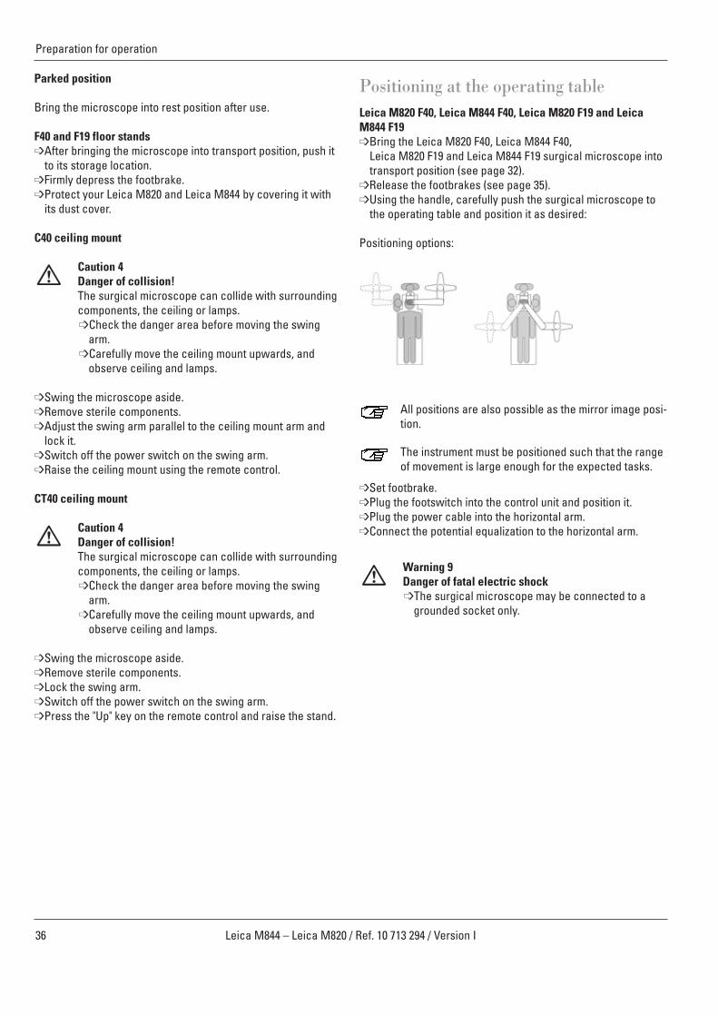
Positioning at the operating tableLeica M820 F40, Leica M844 F40, Leica M820 F19 and LeicaM844 F19➩Bring the Leica M820 F40, Leica M844 F40,
Leica M820 F19 and Leica M844 F19 surgical microscope intotransport position (see page 32).
➩Release the footbrakes (see page 35).➩Using the handle, carefully push the surgical microscope to
the operating table and position it as desired:
Positioning options:
All positions are also possible as the mirror image posi-tion.
The instrument must be positioned such that the rangeof movement is large enough for the expected tasks.
➩Set footbrake. ➩Plug the footswitch into the control unit and position it.➩Plug the power cable into the horizontal arm.➩Connect the potential equalization to the horizontal arm.
Warning 9Danger of fatal electric shock➩The surgical microscope may be connected to a
grounded socket only.
Parked position
Bring the microscope into rest position after use.
F40 and F19 floor stands➩After bringing the microscope into transport position, push it
to its storage location.➩Firmly depress the footbrake.➩Protect your Leica M820 and Leica M844 by covering it with
its dust cover.
C40 ceiling mount
Caution 4Danger of collision!The surgical microscope can collide with surroundingcomponents, the ceiling or lamps.➩Check the danger area before moving the swing
arm.➩Carefully move the ceiling mount upwards, and
observe ceiling and lamps.
➩Swing the microscope aside.➩Remove sterile components.➩Adjust the swing arm parallel to the ceiling mount arm and
lock it.➩Switch off the power switch on the swing arm.➩Raise the ceiling mount using the remote control.
CT40 ceiling mount
Caution 4Danger of collision!The surgical microscope can collide with surroundingcomponents, the ceiling or lamps.➩Check the danger area before moving the swing
arm.➩Carefully move the ceiling mount upwards, and
observe ceiling and lamps.
➩Swing the microscope aside.➩Remove sterile components.➩Lock the swing arm.➩Switch off the power switch on the swing arm.➩Press the "Up" key on the remote control and raise the stand.

37Leica M844 – Leica M820 / Ref. 10 713 294 / Version I
Preparation for operation
Sterile controlsThe controls indicated in the diagram can be provided withsteam-sterilizable handles or covers.
Use the sterilizable handles also when you use steriledisposable drapes; the controls will be easier to grasp.
7 Handles54 Rotary knob for focus fine adjustment56 Rotary knob for tilt head60 Manual zoom emergency drive63 OttoFlexTM II iris diaphragm70 Interpupillary distance setting wheel
Also refer to the "Sterilization" table on page 61.
Before the operation
➩Press the sterile controls into position so that they engage.The rotary knobs 54, 56, 60, 63 and 70 are identical.
Packaging the footswitch in a plastic bag protects itagainst dirt.
Sterile drape for stand
Caution 5Risk of infection!➩Leave sufficient space around the stand to ensure
that the sterile drape does not come into contactwith non-sterile components.
You can also use an optional sterile disposable drape.
➩Release the "All Brakes" functions (not available with LeicaM820 F19 and M844 F19) using the handle and extend theswing arm.
➩Put on sterile gloves.➩Attach all the sterile controls.➩Carefully unpack the sterile drape and pull it over the Leica
M820 and Leica M844 surgical microscopes up to the swingarm.
➩Clamp the protective glass (optional) onto the objective.➩Do not attach the sterile drape too tightly with the provided
ribbons. It must still be easy to operate the instrument.
Check the ease of movement of the instrument.
Follow the instructions provided by the manufacturer ofthe sterile drape.
Ensure that you pull the disposable drape only to theend of the swing arm and fasten it there! Do not coverthe horizontal arm.
70
6063
7
56
54
38 Leica M844 – Leica M820 / Ref. 10 713 294 / Version I
Use
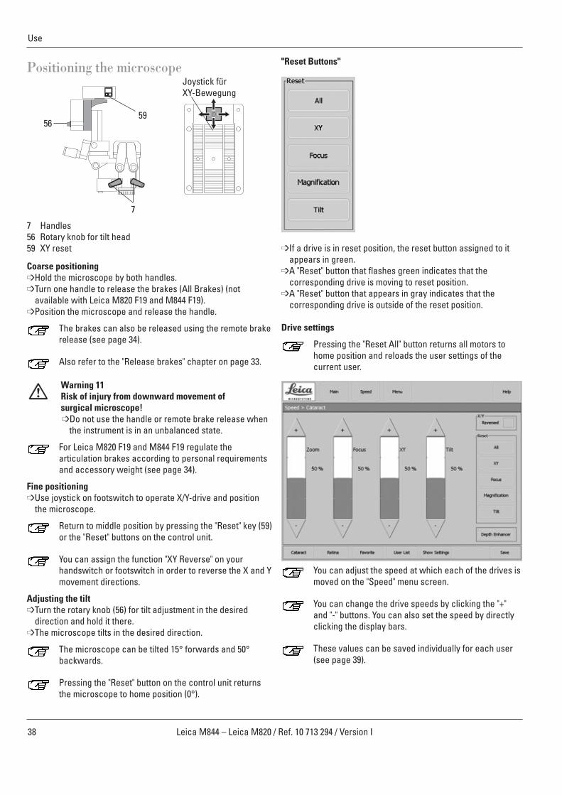
Positioning the microscope
7 Handles56 Rotary knob for tilt head59 XY reset
Coarse positioning➩Hold the microscope by both handles.➩Turn one handle to release the brakes (All Brakes) (not
available with Leica M820 F19 and M844 F19).➩Position the microscope and release the handle.
The brakes can also be released using the remote brakerelease (see page 34).
Also refer to the "Release brakes" chapter on page 33.
Warning 11Risk of injury from downward movement of surgical microscope!➩Do not use the handle or remote brake release when
the instrument is in an unbalanced state.
For Leica M820 F19 and M844 F19 regulate thearticulation brakes according to personal requirementsand accessory weight (see page 34).
Fine positioning➩Use joystick on footswitch to operate X/Y-drive and position
the microscope.
Return to middle position by pressing the "Reset" key (59)or the "Reset" buttons on the control unit.
You can assign the function "XY Reverse" on yourhandswitch or footswitch in order to reverse the X and Ymovement directions.
Adjusting the tilt➩Turn the rotary knob (56) for tilt adjustment in the desired
direction and hold it there.➩The microscope tilts in the desired direction.
The microscope can be tilted 15° forwards and 50°backwards.
Pressing the "Reset" button on the control unit returnsthe microscope to home position (0°).
"Reset Buttons"
➩If a drive is in reset position, the reset button assigned to itappears in green.
➩A "Reset" button that flashes green indicates that thecorresponding drive is moving to reset position.
➩A "Reset" button that appears in gray indicates that the corresponding drive is outside of the reset position.
Drive settings
Pressing the "Reset All" button returns all motors tohome position and reloads the user settings of the current user.
You can adjust the speed at which each of the drives ismoved on the "Speed" menu screen.
You can change the drive speeds by clicking the "+"and "-" buttons. You can also set the speed by directlyclicking the display bars.
These values can be saved individually for each user(see page 39).
5956
7
Joystick für XY-Bewegung
39Leica M844 – Leica M820 / Ref. 10 713 294 / Version I
Use
Adjusting the microscopeAdjusting the illumination
Warning 12Light which is too intensive can damage the retina.➩Safeguard your patients:
short exposure times,low brightness setting,use protective filters (GG420 built in).
We recommend setting the minimal required light intensity for theoperation. Infants, small children, aphakic patients who have nothad their lenses replaced by artificial lenses with UV protection,and persons with eye diseases are at higher risk. The risk is alsoelevated if the person to be treated has been exposed to illumina-tion from the same or a similar ophthalmological instrument withan intense visible light source within the previous 24 hours. Thisapplies especially to patients that have been examined via retinalphotography.The decision with regard to the light intensity to be used must bemade on a case-by-case basis. In any event, the surgeon mustevaluate the risks and benefits of the used light intensity.Damage may occur despite all efforts to minimize the risk of retinal injury by surgical microscopes. Photochemical retinadamage is a possible complication arising from the necessity touse intense light to make eye structures visible during difficultophthalmological processes.
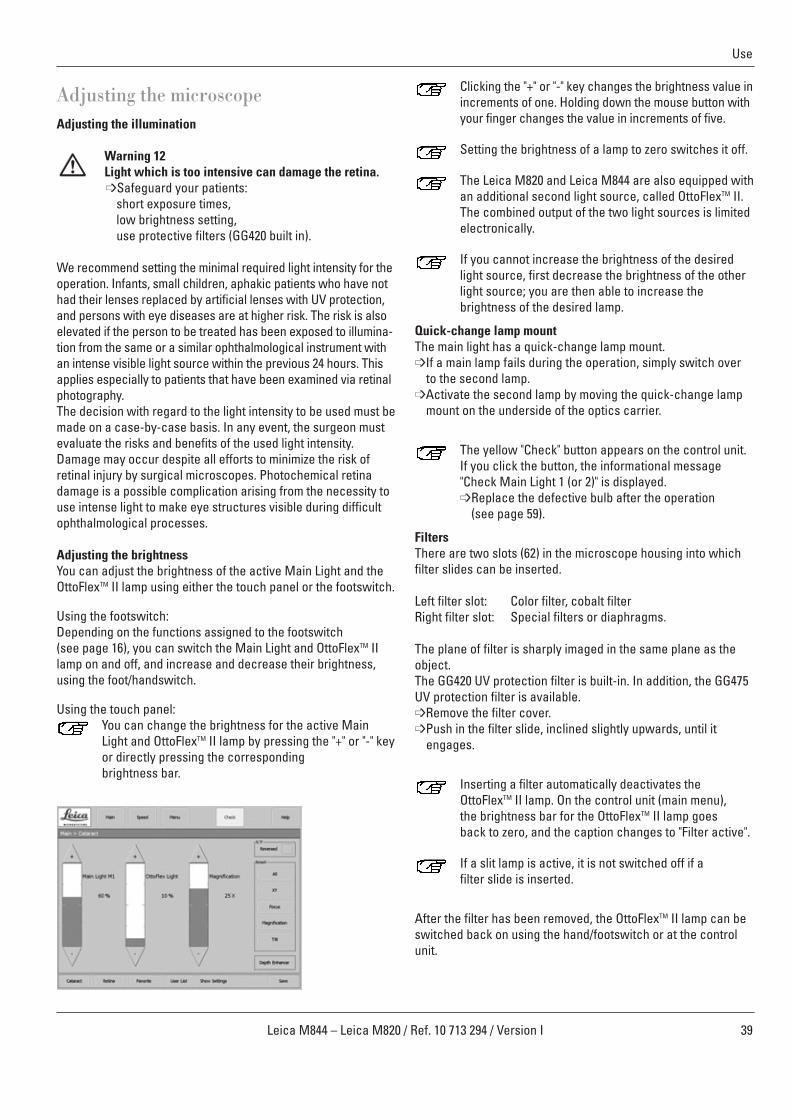
Adjusting the brightnessYou can adjust the brightness of the active Main Light and theOttoFlexTM II lamp using either the touch panel or the footswitch.
Using the footswitch:Depending on the functions assigned to the footswitch(see page 16), you can switch the Main Light and OttoFlexTM IIlamp on and off, and increase and decrease their brightness,using the foot/handswitch.
Using the touch panel:You can change the brightness for the active MainLight and OttoFlexTM II lamp by pressing the "+" or "-" keyor directly pressing the corresponding brightness bar.
Clicking the "+" or "-" key changes the brightness value inincrements of one. Holding down the mouse button withyour finger changes the value in increments of five.
Setting the brightness of a lamp to zero switches it off.
The Leica M820 and Leica M844 are also equipped withan additional second light source, called OttoFlexTM II.The combined output of the two light sources is limitedelectronically.
If you cannot increase the brightness of the desiredlight source, first decrease the brightness of the otherlight source; you are then able to increase thebrightness of the desired lamp.
Quick-change lamp mountThe main light has a quick-change lamp mount. ➩If a main lamp fails during the operation, simply switch over
to the second lamp.➩Activate the second lamp by moving the quick-change lamp
mount on the underside of the optics carrier.
The yellow "Check" button appears on the control unit.If you click the button, the informational message"Check Main Light 1 (or 2)" is displayed.➩Replace the defective bulb after the operation
(see page 59).
FiltersThere are two slots (62) in the microscope housing into whichfilter slides can be inserted.
Left filter slot: Color filter, cobalt filterRight filter slot: Special filters or diaphragms.
The plane of filter is sharply imaged in the same plane as theobject.The GG420 UV protection filter is built-in. In addition, the GG475UV protection filter is available. ➩Remove the filter cover.➩Push in the filter slide, inclined slightly upwards, until it
engages.
Inserting a filter automatically deactivates theOttoFlexTM II lamp. On the control unit (main menu),the brightness bar for the OttoFlexTM II lamp goesback to zero, and the caption changes to "Filter active".
If a slit lamp is active, it is not switched off if a filter slide is inserted.
After the filter has been removed, the OttoFlexTM II lamp can beswitched back on using the hand/footswitch or at the controlunit.

40 Leica M844 – Leica M820 / Ref. 10 713 294 / Version I
Use
40
Adjusting the magnification (zoom)You can adjust the magnification using the footswitch/handswitch or the "Magnification" adjustment bar in the mainmenu of the control unit.
Clicking the "+" or "-" key changes the magnificationvalue in increments of one. Holding down the mousebutton with your finger changes the value in incrementsof five.
You can change the speed at which the zoom motormoves in the "Speed" menu (see page 38).
You can return the zoom motor to the magnification setting saved for the current user using the "Reset Magnification" button (see page 38).
Depth EnhancerYou can activate a double-iris diaphragm to increase the depthof field using the "Depth Enhancer" button.
In the "User Settings" menu, you can assign a defaultstatus of the double-iris diaphragm for each user, orassign it as a footswitch function, under "Tube Settings".
Manually adjusting the magnification (zoom)
Caution 6Destruction of the zoom motor!➩Use the manual adjustment of the zoom motor only if
the zoom motor is defective.
If the zoom motor fails, the zoom can be manually adjusted usingthe rotary knob (60) on the optics carrier.➩Press the rotary knob.➩Set the desired magnification by turning the knob.
Adjusting the focusYou can focus the microscope using the focus keys on thefootswitch.
You can change the speed at which the focus motormoves in the "Speed" menu (see page 38).
You can return the focus motor to the reset position (1/3 up, 2/3 down) by pressing the "Reset" key (59) or the"Reset Focus" button (see page 38).
You can also refocus the 0° assistant’s attachment usinga fine focus adjustment knob (59).
Touch panel
Adjusting brightness and contrast➩Press the brightness/contrast (32) key once. ➩A bar for adjusting the brightness appears on the screen. ➩Change the brightness with the + and - buttons.➩Press the brightness/contrast (32) key again. ➩A bar for adjusting the contrast appears on the screen. ➩Change the contrast with the + and - buttons.➩Press the brightness/contrast button again (32) to save the
values you have set and hide the adjustment bars.
Changing operating modes➩You can switch your control unit between the video, control
unit and DVI modes using the video/control unit mode switch(36).
➩The active mode is indicated by an LED (35 or 37).➩If video mode is active, the video signal received at the video
input (41) is displayed on the monitor.➩If control unit mode is active, the touch panel displays a menu
interface in which the microscope can be controlled.➩If the DVI mode is active, the DVI signal (e.g. Leica MDRS4
video system) is displayed and both LEDs light up.
While video mode is active, any warning that mayoccur is indicated by an audible signal. This audiowarning signal can be deactivated by your servicepartner if desired.
Menu structure
71 Operational mode (light/magnification settings)72 Operational mode (drive settings)73 Configuration menu74 Static menu bar (does not change)75 Displays help texts for certain topics76 Dynamic button bar77 Display area with status bar78 Warning messages
71 72 73 74 78 75
7677
32 33 34 35 36 37

You can click the "User List" button to open a two-page user listfrom which you can select from up to 30 saved users.
➩Click the "1-15" or "16-30" button to switch between pages.
When the user list is open, it can be edited at any time(see page 42).
When you select a user, an informational screen forthat user appears that specifies the tube settings thatare needed, as well as the current footswitch/handswitch assignments. Press "Continue".
Before starting every operation make sure yourpersonal user settings are selected and make yourselffamiliarize with your footswitch configuration.
If you have assigned the "StepCycle" function to thefootswitch we recommend tthat you check the StepCycleTM procedure without patient before startingthe operation.
41Leica M844 – Leica M820 / Ref. 10 713 294 / Version I
Use
Switching the microscope on
Warning 13Motors return to their home positions➩Before switching on your Leica M820 / Leica M844,
ensure that the travel paths of the XY, zoom andfocus motors are free of obstructions. The tilt motoris not moved.
➩Switch on your microscope at the power switch of thehorizontal arm.
➩As soon as the main illuminator lights up, your microscope isready to use.
After the surgical microscope is switched on, thesettings of the last active user are loaded.
If the power supply of your microscope is accidentallyinterrupted for a short period (<20 ±5 seconds), themicroscope carries out a fast startup:
• All motors are in the same position as before.• All illumination settings remain the same.• XY reverse status is restored where applicable.• If the StepCycleTM function has been selected, it is in
step 0 (see page 45).• The fast start-up function can be disabled in the
Service menu.
In operational mode, the status bar displays the currentuser and specifies the current location in the menu atall times.
Selecting usersIn the "Main" and "Speed" menu screens, the four buttons"Cataract", "Retina", "Favorite" and "User List" appear in thedynamic button bar at all times.
The users "Cataract" and "Retina" are default users provided byLeica.
You can adjust the settings of these default users asdesired (see page 42).
You can store a frequently used profile under the user "Favorite"(see page 42).
You can click the "Show Settings" button at any time tosee an overview of the user settings of the currentuser.
42 Leica M844 – Leica M820 / Ref. 10 713 294 / Version I
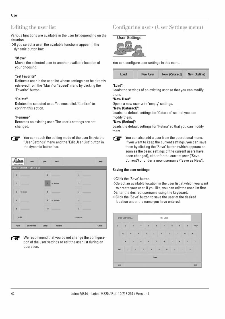
Editing the user listVarious functions are available in the user list depending on thesituation.➩If you select a user, the available functions appear in the
dynamic button bar:
"Move"Moves the selected user to another available location ofyour choosing.
"Set Favorite"Defines a user in the user list whose settings can be directlyretrieved from the "Main" or "Speed" menu by clicking the"Favorite" button.
"Delete"Deletes the selected user. You must click "Confirm" toconfirm this action.
"Rename"Renames an existing user. The user's settings are notchanged.
You can reach the editing mode of the user list via the"User Settings" menu and the "Edit User List" button inthe dynamic button bar.
We recommend that you do not change the configura-tion of the user settings or edit the user list during anoperation.
Use
Configuring users (User Settings menu)
You can configure user settings in this menu.
"Load":Loads the settings of an existing user so that you can modifythem."New User"Opens a new user with "empty" settings."New (Cataract)":Loads the default settings for "Cataract" so that you can modify them."New (Retina)":Loads the default settings for "Retina" so that you can modifythem.
You can also add a user from the operational menu.If you want to keep the current settings, you can savethem by clicking the "Save" button (which appears assoon as the basic settings of the current users havebeen changed), either for the current user ("SaveCurrent") or under a new username ("Save as New").
Saving the user settings:
➩Click the "Save" button.➩Select an available location in the user list at which you want
to create your user. If you like, you can edit the user list first.➩Enter the desired username using the keyboard.➩Click the "Save" button to save the user at the desired
location under the name you have entered.
43Leica M844 – Leica M820 / Ref. 10 713 294 / Version I
Use
Setting the light start values
You can set the start values for the main lamps, the OttoFlexTM IIlamp and the magnification on this screen.➩Clicking the "+" or "-" key changes the values in increments of
one.➩Holding down the key with your finger changes the value in
increments of five.
You can also set the desired value by directly clickingthe bars.
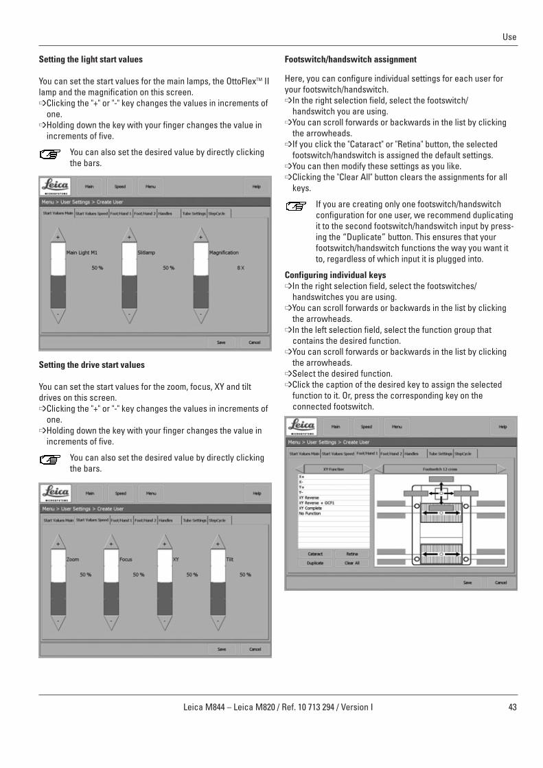
Setting the drive start values
You can set the start values for the zoom, focus, XY and tiltdrives on this screen.➩Clicking the "+" or "-" key changes the values in increments of
one.➩Holding down the key with your finger changes the value in
increments of five.
You can also set the desired value by directly clickingthe bars.
Footswitch/handswitch assignment
Here, you can configure individual settings for each user foryour footswitch/handswitch.➩In the right selection field, select the footswitch/
handswitch you are using. ➩You can scroll forwards or backwards in the list by clicking
the arrowheads.➩If you click the "Cataract" or "Retina" button, the selected
footswitch/handswitch is assigned the default settings.➩You can then modify these settings as you like.➩Clicking the "Clear All" button clears the assignments for all
keys.
If you are creating only one footswitch/handswitch configuration for one user, we recommend duplicatingit to the second footswitch/handswitch input by press-ing the “Duplicate” button. This ensures that yourfootswitch/handswitch functions the way you want itto, regardless of which input it is plugged into.
Configuring individual keys➩In the right selection field, select the footswitches/
handswitches you are using. ➩You can scroll forwards or backwards in the list by clicking
the arrowheads.➩In the left selection field, select the function group that
contains the desired function. ➩You can scroll forwards or backwards in the list by clicking
the arrowheads.➩Select the desired function.➩Click the caption of the desired key to assign the selected
function to it. Or, press the corresponding key on theconnected footswitch.

44 Leica M844 – Leica M820 / Ref. 10 713 294 / Version I
Use
Overview of function groupsDrive: Magnification +
Magnification -Focus +Focus -Tilt +Tilt-No function
Extra: AD.F.1 toggleAD.F.1 pulseAD.F.2 toggleAD.F.2 pulseOCF1 toggleOCF1 pulseOCF2 toggleOCF2 pulseOCF3 toggleOCF4 pulseStepCycleDepth Enhancer ToggleNo function
The "Toggle" function changes the status of a function(such as On/Off). The "Pulse" function continuouslychanges a status (such as increasing the brightness).
Light: Mainlight on/offOttoFlex Light on/offMainlight +Mainlight -OttoFlex Light +OttoFlex Light -All Lights on/offNo function
Reset: Reset MagnificationReset FocusReset TiltReset XYReset AllNo function
XY function: X+X-Y+Y-XY ReverseXY Reverse + OCF1XY CompleteNo function
With the "XY Complete" function, you can assign all fourfunctions of the joystick simultaneously.
Handle assignmentYou can assign up to three functions of your choosing to thehandle. The fourth function must always be "All Brakes".However, you can assign this function to any position you like.
➩Select the handle in the right selection field. ➩You can scroll forwards or backwards in the list by clicking
the arrowheads.➩In the left selection field, select the function group that
contains the desired function. ➩You can scroll forwards or backwards in the list by clicking
the arrowheads.➩Select the desired function.➩Click the caption of the desired key to assign the selected
function to it.
For the handle, the additional functiongroup with thefunctions "All Brakes" (releases all brakes) and "Selected Brakes" (releases all brakes except theup/down brake) are also available. (Not availablewith Leica M820 F19 and Leica M844 F19.)
If you would prefer a different brake assignment,please contact your service technician.
Tube SettingsOn this page, you can store the diopter values and interpupillarydistance for each user. You can also activate or deactivate the"Depth Enhancer" as a basic setting for each user.
45Leica M844 – Leica M820 / Ref. 10 713 294 / Version I
Use
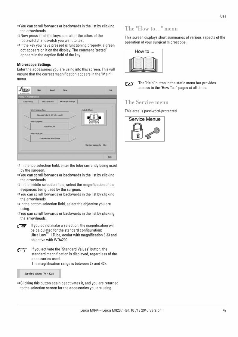
StepCycleTM
Using this function, you can save the following parameters forvarious frequently recurring phases (cycles) of the operation:
Main light brightnessOttoFlex brightnessMagnificationFocusDepth EnhancerOCF1AD.F.
Caution 7 Risk of injury➩Look especially after the required safety distance ifyou use the StepCycleTM function together with acces-sories from other manufacturers that reduces theworking distance to less than 140 mm (non-contactwide-angle observation systems) as focus togetherwith StepCycleTM a semiautomated function.
For the StepCycleTM function to be available, you mustfirst assign it to a key on your footswitch/handswitch.Then, the "Rec.Cycle" button appears in the dynamicbutton bar.
You can create an individual StepCycleTM procedure foreach user.
StepCycleTM recording mode➩From the "Main" or "Speed" menu, double-click the
"Rec. Cycle" button to activate it.➩Press the button on your footswitch/handswitch to which
you have assigned the "Rec.Cycle" function.➩The currently set values for the StepCycleTM parameters
are saved.➩You can save a maximum of 10 StepCycleTM settings.➩Exit the StepCycleTM teach-in mode by double-clicking
the "Rec. Cycle" button.➩Press "Save" to store your StepCycleTM settings.
It is only possible to store a complete StepCycleTM
cycle. Individual steps cannot be modified.
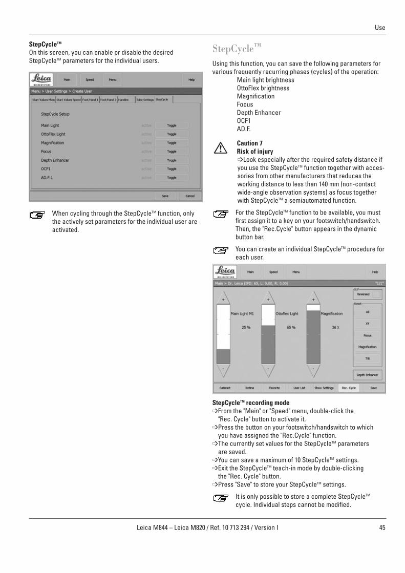
StepCycleTM
On this screen, you can enable or disable the desiredStepCycleTM parameters for the individual users.
When cycling through the StepCycleTM function, onlythe actively set parameters for the individual user areactivated.

46 Leica M844 – Leica M820 / Ref. 10 713 294 / Version I
Use
The Maintenance menu
Hour meter for the bulbs (Lamp History)This screen displays the operating hours for each of thefollowing bulbs: Main 1, Main 2 and Otto Flex Light.
➩Whenever you replace a bulb, reset the bulb's hour meter to0 by double-clicking the "Reset" button.
Check SwitchesOn this screen, you can test the footswitches/handswitchesand handles you are using.
➩In the top right selection field, select the connection you areusing.
➩You can scroll forwards or backwards in the list by clickingthe arrowheads.
➩In the bottom right selection field, select the footswitch/handswitch you want to check.
Running through the StepCycleTM
If StepCycleTM settings have been saved for a user, the right status bar displays information indicating which step the user iscurrently in, and how many steps there are total:
• Step 0 means: basic setting of the user• 1/x means: 1 of x steps
➩In the "Main" or "Speed" menu, deactivate the "Rec. Cycle"button.
➩Activate the key of your footswitch/handswitch to which the"StepCycle" function is assigned by clicking it.
➩You run through a continuous loop of the stored StepCycleTM
settings.
If you load a new user or trigger an Auto Reset, you arereturned to Step 0.
Auto ResetIf you move the swing arm up to its end position after the operation, you trigger the Auto Reset function:
• All of the motors–zoom, focus and XY–move to theirreset position.
• The tilt motor is not moved.• The current user settings are reloaded.• The illumination is switched off.
➩If you move your Leica M844 or Leica M820 back down overthe OP field, the illumination switches back on and your LeicaM844 or Leica M820 is ready to use immediately.
This function can be deactivated by your Leica servicetechnician.
47Leica M844 – Leica M820 / Ref. 10 713 294 / Version I
Use
The "How to..." menuThis screen displays short summaries of various aspects of theoperation of your surgical microscope.
The "Help" button in the static menu bar providesaccess to the "How To..." pages at all times.
The Service menuThis area is password-protected.
➩You can scroll forwards or backwards in the list by clickingthe arrowheads.
➩Now press all of the keys, one after the other, of thefootswitch/handswitch you want to test.
➩If the key you have pressed is functioning properly, a greendot appears on it on the display. The comment "tested"appears in the caption field of the key.
Microscope SettingsEnter the accessories you are using into this screen. This willensure that the correct magnification appears in the "Main"menu.
➩In the top selection field, enter the tube currently being usedby the surgeon.
➩You can scroll forwards or backwards in the list by clickingthe arrowheads.
➩In the middle selection field, select the magnification of theeyepieces being used by the surgeon.
➩You can scroll forwards or backwards in the list by clickingthe arrowheads.
➩In the bottom selection field, select the objective you areusing.
➩You can scroll forwards or backwards in the list by clickingthe arrowheads.
If you do not make a selection, the magnification willbe calculated for the standard configuration: Ultra Low
TMII Tube, ocular with magnification 8.33 and
objective with WD=200.
If you activate the "Standard Values" button, thestandard magnification is displayed, regardless of theaccessories used. The magnification range is between 7x and 42x.
➩Clicking this button again deactivates it, and you are returnedto the selection screen for the accessories you are using.

48 Leica M844 – Leica M820 / Ref. 10 713 294 / Version I
Safety notes
Intended use
• The Leica surgical microscope is an optical instrument forimproving the visibility of objects through magnification andillumination. It can be applied for observation and documen -tation and for human and veterinary medical treatment.
• The Leica surgical microscope may be used only in closedrooms and must be placed on a solid floor or attached to astrong ceiling.
• The Leica M820 and Leica M844 surgical microscopes are sub-ject to special precautionary measures for electromagnetic compatibility. They must be installed and put into operation inaccordance with the guidelines, manufacturer's declarationsand recommended safety distances (Tables 201, 202, 204, and206 from EN 60601-1-2:2001).
• Portable and mobile as well as stationary HF communicationsequipment can have a negative effect on the reliability of theLeica M820 and Leica M844 surgical microscopes.
Directions for the person responsible forthe instrument
➩Ensure that the surgical microscope is used only by personsqualified to do so.
➩Ensure that this user manual is always available at the placewhere the surgical microscope is in use.
➩Carry out regular inspections to make certain that the authorized users are adhering to safety requirements.
➩When instructing new users, do so thoroughly and explainthe meanings of the warning signs and messages.
➩Assign individual responsibilities for starting, operating andservicing the Leica surgical microscope and monitor theobservance of these responsibilities.
➩Only use the surgical microscope if it is free of defects.➩Inform your Leica representative or Leica Microsystems
(Schweiz) AG, Surgical Division, 9435 Heerbrugg, Switzerland,immediately if you detect a product defect that couldpotentially cause injury or harm.
➩If you use accessories made by third-party manufacturerswith the Leica surgical microscope, be sure that each suchmanufacturer confirms the safety-engineering, harmlessusability of the product and observe the product's user manual.
➩Modifications to or service on the surgical microscope maybe carried out only by technicians who are explicitlyauthorized by Leica to do so.
➩Only original Leica replacement parts may be used in servicing the product.
➩After service work or technical modifications, the unit mustbe reconfigured with observance to our technicalrequirements.
➩If the unit is modified or serviced by unauthorized persons,is improperly maintained (as long as maintenance was notcarried out by us), or is handled improperly, Leica will notaccept any liability.
➩The influence on other devices by the Leica surgicalmicroscope has been tested in accordance with EN 60 601-1-2. The system passed the emissions and immunity test. The standard preventive measures and safetyregulations pertaining to electromagnetic and other radiationhave to be observed
User qualifications
The Leica surgical microscope may only be used by physiciansand medical assistance personnel with appropriate qualifi -cations who have been instructed in the use of the instrument.Specific training is not required.
Directions for the operator of theinstrument
➩Follow the instructions described here.➩Follow the directions provided by your employer regarding
work organization and safety.
Stability (floor stands only)When moved in OP, the swing arm must be folded up andlocked and the brakes must be applied, otherwise the swingarm may drift out of control and the stand could topple.
Hazards due to moveable partsThis section describes uses that, inadvertently, could lead tohazardous situations.
• Add accessories and balance the stand before the operation,and never over the field of operation.
• Never put your hand between the gas spring and the swingarm; it could become trapped when the swing arm is moved.
• Do not put your fingers between the microscope and thefocusing drive; they could get crushed.
Floor stand:• When displacing the stand, push it. Do not pull it. Feet in
lightweight shoes could become trapped beneath the casingof the base.
• The footbrakes must remain engaged throughout theoperation.
Electrical connectionsThe control unit may be opened only by a Leica-approvedservice technician.
AccessoriesOnly the following accessories may be used with the LeicaM820 and Leica M844 surgical microscopes:• The Leica accessories described in this user manual.• Other accessories, provided that these have been expressly
approved by Leica as being technically safe in this context.

49Leica M844 – Leica M820 / Ref. 10 713 294 / Version I
Safety notes
Dangers of useWarning 1Motors return to their home positions➩Before switching on the microscope, ensure that the
travel paths of the X- and Y-axes and the zoommotor are free of obstructions.
➩Check the Main Light 1/2 and OttoFlexTM II lamps.Replace defective bulbs before the operationbegins.
➩Test all handswitch and footswitch functions.➩Check the function of the brakes using the handles
and remote brake release (see page 33).
Warning 2Danger of fatal electric shock➩Operate the system only with all equipment in its
proper position (all covers fitted, doors closed).
Warning 3Risk of injury through surgical microscope movingdown!➩Complete all preparations and adjustments to the
stand before the operation.➩Never balance or re-equip the instrument over the
field of operation.➩Before re-equipping, always lock the swing arm.➩After re-equipping, always rebalance the
microscope on the swing arm.➩Do not release the brakes when the instrument is in
an unbalanced state.➩Before re-equipping during the operation, first swing
the microscope away from the operating field.
Warning 4Danger of burns➩The lamp housing and cover may become hot during
use.
Warning 5There is a danger of injury to the patient as a result ofchanging the working distance using the motorizedadjustment of the telescopic stand if the working dis-tance falls below the minimum of 140 mm due to theuse of accessories (such as wide-angle observationsystems).➩The footswitch function for moving the telescopic
stand up and down may not be used in combinationwith accessories that cause the working distance tofall below the minimum of 140 mm.
➩Before up/down movements, always check first toensure that the range of movement is free of obstructions.
Warning 6Risk of injury through surgical microscope movingdown!➩Never balance or re-equip the instrument over the
field of operation.➩After re-equipping, always rebalance the
microscope on the swing arm.
Warning 7Risk of injury through surgical microscope movingdown!➩Always lock the swing arm:
• when transporting the microscope • when changing equipment
Warning 8Risk of injury through surgical microscope movingdown!➩Complete all preparations and adjustments to the
stand before the operation.➩If settings need to be altered during the operation,
first swing the microscope away from the operatingfield.
➩If the microscope needs to be re-equipped, do thisbefore the operation.
➩Before re-equipping, always lock the swing arm.➩Do not use the handle or remote brake release
when the instrument is in an unbalanced state.
Warning 9Beware of: • Uncontrolled lateral movement of the swing arm!• Tilting of the stand!• Feet in lightweight shoes could become trapped
beneath the casing of the base.➩Before transport, always set the Leica M820 F19 and
Leica M844 F19 surgical microscopes to thetransport position.
➩Never move the stand in the extended condition.➩Always push the instrument to displace it;
never pull it.➩Never roll over cables lying on the floor.
Warning 10Danger of fatal electric shock➩The surgical microscope may be connected to a
grounded socket only.
Warning 11Risk of injury through surgical microscope movingdown!➩Do not use the handle or remote brake release
when the instrument is in an unbalanced state.
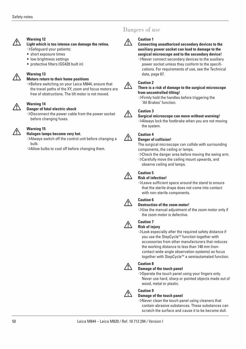
50 Leica M844 – Leica M820 / Ref. 10 713 294 / Version I
Safety notes
Dangers of useCaution 1Connecting unauthorized secondary devices to the auxiliary power socket can lead to damage to thesurgical microscope and to the secondary device!➩Never connect secondary devices to the auxiliary
power socket unless they conform to the specifi -cations. For requirements of use, see the Technicaldata, page 67.
Caution 2There is a risk of damage to the surgical microscopefrom uncontrolled tilting!➩Firmly hold the handles before triggering the
"All Brakes" function.
Caution 3Surgical microscope can move without warning!➩Always lock the footbrake when you are not moving
the system.
Caution 4Danger of collision!The surgical microscope can collide with surroundingcomponents, the ceiling or lamps.➩Check the danger area before moving the swing arm.➩Carefully move the ceiling mount upwards, and
observe ceiling and lamps.
Caution 5Risk of infection!➩Leave sufficient space around the stand to ensure
that the sterile drape does not come into contact with non-sterile components.
Caution 6Destruction of the zoom motor!➩Use the manual adjustment of the zoom motor only if
the zoom motor is defective.
Caution 7 Risk of injury➩Look especially after the required safety distance if
you use the StepCycleTM function together with accessories from other manufacturers that reducesthe working distance to less than 140 mm (non-contact wide-angle observation systems) as focustogether with StepCycleTM a semiautomated function.
Caution 8Damage of the touch panel➩Operate the touch panel using your fingers only.
Never use hard, sharp or pointed objects made out ofwood, metal or plastic.
Caution 9Damage of the touch panel➩Never clean the touch panel using cleaners that
contain abrasive substances. These substances canscratch the surface and cause it to be become dull.
Warning 12Light which is too intense can damage the retina.➩Safeguard your patients:• short exposure times• low brightness settings• protective filters (GG420 built in)
Warning 13Motors return to their home positions➩Before switching on your Leica M844, ensure that
the travel paths of the XY, zoom and focus motors arefree of obstructions. The tilt motor is not moved.
Warning 14Danger of fatal electric shock➩Disconnect the power cable from the power socket
before changing fuses.
Warning 15Halogen lamps become very hot.➩Always switch off the control unit before changing a
bulb.➩Allow bulbs to cool off before changing them.
51Leica M844 – Leica M820 / Ref. 10 713 294 / Version I
Guidance and manufacturer's declaration
Manufacturer's declaration of electromagnetic compatibility (EMC)This "Guidance and manufacturer's declaration" document is based on EN 60601-1-2:2001.
Table 201 from EN 60601-1-2:2001
Guidance and manufacturer's declaration – electromagnetic emissions
The Leica M820 and Leica M844 surgical microscopes are intended for use in the electromagnetic environment specified below. The customer or the user of the Leica M820 and Leica M844 surgical microscopes should assure that they are used in such anenvironment.
Emissions test Compliance Electromagnetic environment – guidance
HF emissions Group 1 The Leica M820 and Leica M844 surgical microscopes use HF energy according to CISPR 11 only for its internal function. Therefore, its HF emissions are very low and
are not likely to cause any interference in nearby electronic equipment.
HF emissions Class A The Leica Leica M820 and Leica M844 surgical microscopes are suitable according to CISPR 11 for use in establishments other than domestic and those directly
connected to the public low-voltage power supply network that suppliesbuildings used for domestic purposes.
Harmonic emissions Class AIEC 61000-3-2
Voltage fluctuations/ Compliantflicker emissionsIEC 61000-3-3

52 Leica M844 – Leica M820 / Ref. 10 713 294 / Version I
Guidance and manufacturer's declaration
Table 202 from EN 60601-1-2:2001
Guidance and manufacturer's declaration – electromagnetic immunity
The Leica M820 and Leica M844 surgical microscopes are intended for use in the electromagnetic environment specified below.The customer or the user of the Leica M820 and Leica M844 surgical microscopes should assure that they are used in such anenvironment.
Immunity test IEC 60601 test level Compliance level Electromagnetic environment – guidance
± 6 KV ± 6 KVcontact contact
± 8 kV air ± 8 kV air
± 2 KV for ± 2 KV forpower supply lines power supply lines
± 1 KV for input/ ± 1 KV for input/output lines output lines
± 1 KV ± 1 KV differential mode differential mode
± 2 kV ± 2 kVcommon mode common mode
<5% UT (>95% <5% UT (>95% dip in UT) dip in UT)for 1/2 period for 1/2 period
40% UT (60% 40% UT (60% dip in UT) dip in UT) for 5 cycles for 5 cycles
70% UT (30% 70% UT (30% dip in UT) dip in UT) for 25 cycles for 25 cycles
<5% UT (>95% <5% UT (>95% dip in UT) dip in UT) for 5 sec. for 5 sec.
3 A/m Not applicable
Note: UT is the a.c. mains voltage prior to application of the test level.
Floors should be of wood, concrete orceramic tile. If floors are covered withsynthetic material, the relative humidityshould be at least 30%.
Mains power quality should be that of a typical commercial or hospital environment.
Mains power quality should be that of a typical commercial or hospital environment.
Mains power quality should be that of a typical commercial or hospital environment.If the user of the Leica M820 and Leica M844surgical microscopes requires continuedoperation during power mains interruptions,it is recommended that the Leica M820 andLeica M844 surgical microscopes bepowered from an uninterruptible power supply or a battery.
Electrostaticdischarge (ESD) IEC 61000-4-2
Electrical fast transient/burst IEC 61000-4-4
Surges IEC 61000-4-5
Voltage dips,short interruptionsand voltage variations onpower supply lines IEC 61000-4-11
Power frequency (50/60 Hz)magnetic fieldIEC 61000-4-8
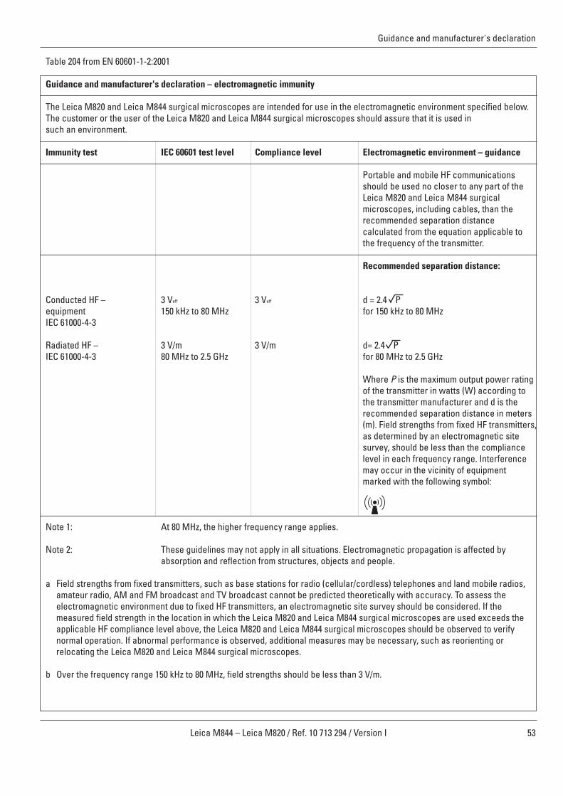
53Leica M844 – Leica M820 / Ref. 10 713 294 / Version I
Guidance and manufacturer's declaration
Table 204 from EN 60601-1-2:2001
Guidance and manufacturer's declaration – electromagnetic immunity
The Leica M820 and Leica M844 surgical microscopes are intended for use in the electromagnetic environment specified below. The customer or the user of the Leica M820 and Leica M844 surgical microscopes should assure that it is used in such an environment.
Immunity test IEC 60601 test level Compliance level Electromagnetic environment – guidance
Portable and mobile HF communicationsshould be used no closer to any part of theLeica M820 and Leica M844 surgicalmicroscopes, including cables, than therecommended separation distancecalculated from the equation applicable tothe frequency of the transmitter.
Recommended separation distance:
Conducted HF – 3 Veff 3 Veff d = 2.4 P equipment 150 kHz to 80 MHz for 150 kHz to 80 MHz IEC 61000-4-3
Radiated HF – 3 V/m 3 V/m d= 2.4 P IEC 61000-4-3 80 MHz to 2.5 GHz for 80 MHz to 2.5 GHz
Where P is the maximum output power ratingof the transmitter in watts (W) according tothe transmitter manufacturer and d is the recommended separation distance in meters(m). Field strengths from fixed HF transmitters,as determined by an electromagnetic sitesurvey, should be less than the compliancelevel in each frequency range. Interferencemay occur in the vicinity of equipmentmarked with the following symbol:
Note 1: At 80 MHz, the higher frequency range applies.
Note 2: These guidelines may not apply in all situations. Electromagnetic propagation is affected byabsorption and reflection from structures, objects and people.
a Field strengths from fixed transmitters, such as base stations for radio (cellular/cordless) telephones and land mobile radios,amateur radio, AM and FM broadcast and TV broadcast cannot be predicted theoretically with accuracy. To assess theelectromagnetic environment due to fixed HF transmitters, an electromagnetic site survey should be considered. If themeasured field strength in the location in which the Leica M820 and Leica M844 surgical microscopes are used exceeds theapplicable HF compliance level above, the Leica M820 and Leica M844 surgical microscopes should be observed to verify normal operation. If abnormal performance is observed, additional measures may be necessary, such as reorienting or relocating the Leica M820 and Leica M844 surgical microscopes.
b Over the frequency range 150 kHz to 80 MHz, field strengths should be less than 3 V/m.
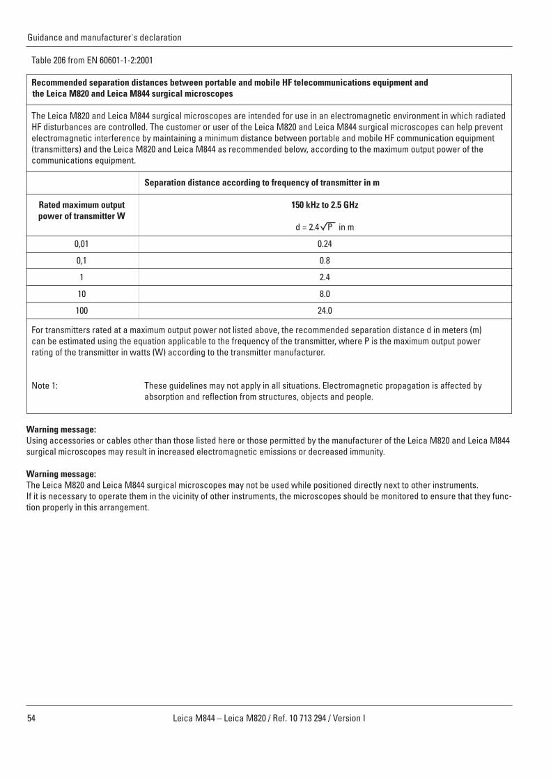
54 Leica M844 – Leica M820 / Ref. 10 713 294 / Version I
Guidance and manufacturer's declaration
Table 206 from EN 60601-1-2:2001
Recommended separation distances between portable and mobile HF telecommunications equipment and the Leica M820 and Leica M844 surgical microscopes
The Leica M820 and Leica M844 surgical microscopes are intended for use in an electromagnetic environment in which radiatedHF disturbances are controlled. The customer or user of the Leica M820 and Leica M844 surgical microscopes can help preventelectromagnetic interference by maintaining a minimum distance between portable and mobile HF communication equipment(transmitters) and the Leica M820 and Leica M844 as recommended below, according to the maximum output power of thecommunications equipment.
Separation distance according to frequency of transmitter in m
Rated maximum output 150 kHz to 2.5 GHzpower of transmitter W
d = 2.4 P in m
0,01 0.24
0,1 0.8
1 2.4
10 8.0
100 24.0
For transmitters rated at a maximum output power not listed above, the recommended separation distance d in meters (m)can be estimated using the equation applicable to the frequency of the transmitter, where P is the maximum output powerrating of the transmitter in watts (W) according to the transmitter manufacturer.
Note 1: These guidelines may not apply in all situations. Electromagnetic propagation is affected byabsorption and reflection from structures, objects and people.
Warning message:Using accessories or cables other than those listed here or those permitted by the manufacturer of the Leica M820 and Leica M844surgical microscopes may result in increased electromagnetic emissions or decreased immunity.
Warning message:The Leica M820 and Leica M844 surgical microscopes may not be used while positioned directly next to other instruments. If it is necessary to operate them in the vicinity of other instruments, the microscopes should be monitored to ensure that they func-tion properly in this arrangement.
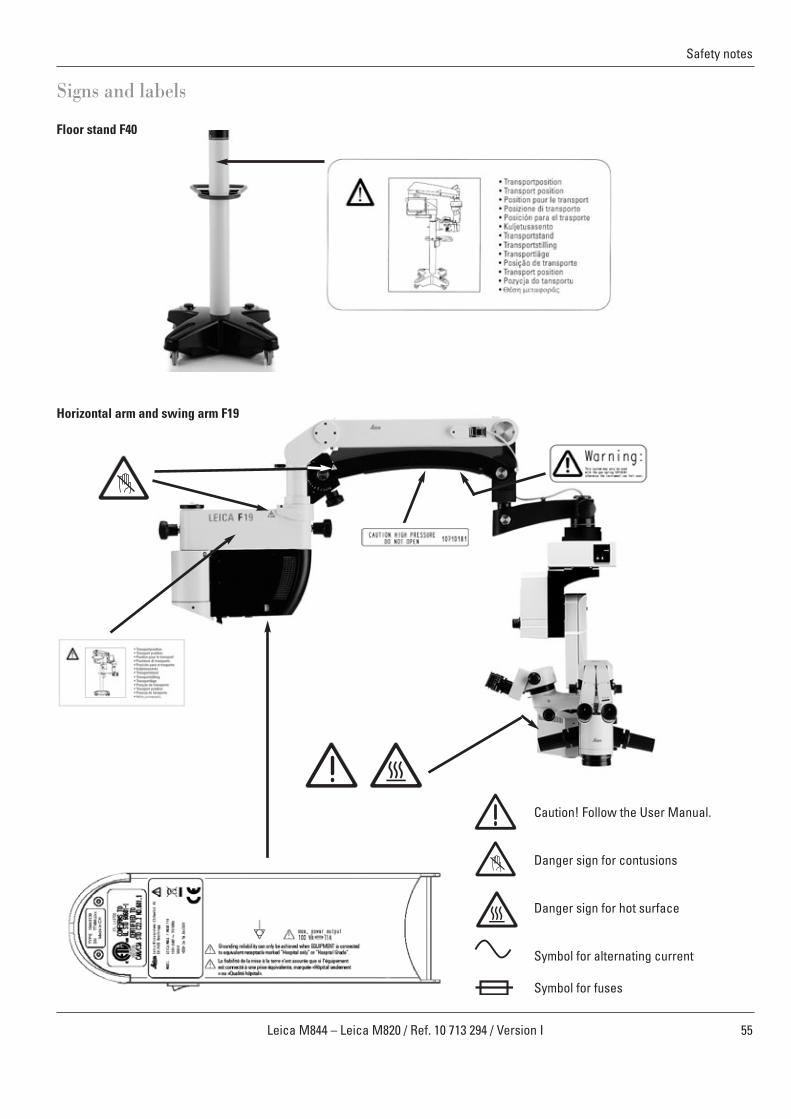
55Leica M844 – Leica M820 / Ref. 10 713 294 / Version I
Caution! Follow the User Manual.
Danger sign for contusions
Danger sign for hot surface
Symbol for alternating current
Symbol for fuses
Safety notes
Signs and labels
Floor stand F40
Horizontal arm and swing arm F19
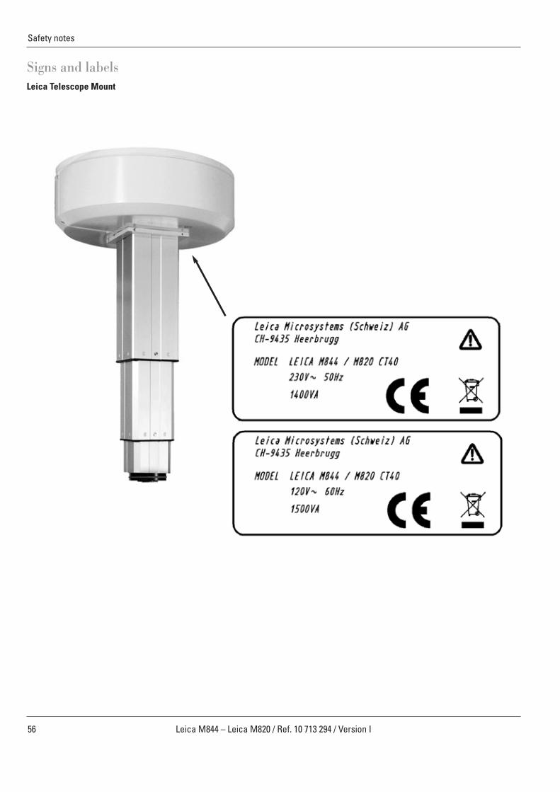
Safety notes
56 Leica M844 – Leica M820 / Ref. 10 713 294 / Version I
Signs and labelsLeica Telescope Mount
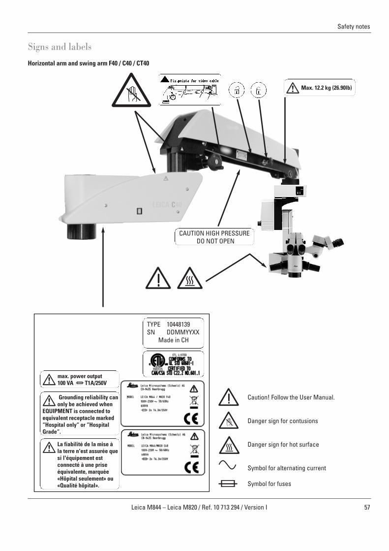
57Leica M844 – Leica M820 / Ref. 10 713 294 / Version I
Safety notes
Signs and labels
Grounding reliability canonly be achieved when
EQUIPMENT is connected toequivalent receptacle marked“Hospital only“ or “HospitalGrade“.
max. power output100 VA T1A/250V
La fiabilité de la mise àla terre n'est assurée quesi l'équipement estconnecté à une priseéquivalente, marquée«Hôpital seulement» ou«Qualité hôpital».
TYPE 10448139SN DDMMYYXX
Made in CH
Horizontal arm and swing arm F40 / C40 / CT40
Caution! Follow the User Manual.
Danger sign for contusions
Danger sign for hot surface
Symbol for alternating current
Symbol for fuses
CAUTION HIGH PRESSUREDO NOT OPEN
Max. 12.2 kg (26.90lb)

58 Leica M844 – Leica M820 / Ref. 10 713 294 / Version I
Care and maintenance
58
Maintenance instructions
• Put a dust cover over the instrument during breaks in work.• Keep accessories in a dust-free place when not in use.• Remove dust with a pneumatic rubber pump and a soft brush.• Clean the objectives and eyepieces with special optics
cleaning cloths and pure alcohol.• Protect the surgical microscope from damp, vapors, acids,
alkalis, and corrosive substances.Do not keep chemicals near the instrument.
• Protect the surgical microscope from improper handling.Install other device sockets or unscrew optical systems andmechanical parts only when explicitly instructed to do so inthis user manual.
• Protect the surgical microscope from oil and grease.Never oil or grease the guide surfaces or mechanical parts.
• Remove coarse debris with a moistened disposable cloth.• For disinfecting the surgical microscope, use compounds
from the surface disinfecting group based on the followingactive ingredients:aldehydes,alcohols,quaternary ammonia compounds.
Due to potential damage to the materials, never usesubstances based on
halogen splitting compounds,strong organic acids,oxygen splitting compounds.
Follow the disinfectant manufacturer’s instructions.
It is recommended to conclude a service contract withLeica Service.
Cleaning the touch panel
➩Before cleaning the touch panel, switch off your Leica M820and Leica M844 and disconnect it from the power supply.
➩Use a soft, lint-free cloth to clean the touch panel.➩Do not apply cleaning agent directly to the touch panel;
rather, apply it to the cleaning cloth.➩Use a commercially available glass/eyeglass cleaner or plas-
tic cleaner to clean the touch panel. ➩Do not apply pressure to the touch panel while cleaning it.
The touch panel is resistant to most disinfectants usedin the medical field.
Caution 8Damage of the touch panel➩Operate the touch panel using your fingers only.
Never use hard, sharp or pointed objects made outof wood, metal or plastic.
Caution 9Damage of the touch panel➩Never clean the touch panel using cleaners that
contain abrasive substances. These substances canscratch the surface and cause it to be become dull.
Maintenance
The operating microscopes Leica M820 F40, Leica M820 F19,Leica M820 CT 40 as well as Leica M844 F40, Leica M844 F19,Leica M844 CT40 in principle are maintenance free.
The operating microscopes Leica M820 C40 and Leica M844 C40(Leica ceiling mount with lift arm) – in order to keep safety andreliability – are subject to regular maintenance inspectionswith the following minimum time intervals:
At the latest 5 years after first bringing into service and then atleast once a year:
Inspection by trained technicians:
• Functional and visual inspection of the entire ceiling mount• Visual inspection of all cables• Electronically safety test• Check and test of the lift system, in particular all bearings
for free movement• Lubrication of the spindle
Only lubricate the spindle with STABURAGS NBU 12/300 KP (Klüber LubricationMünchen KG, Deutschland) No other lubricants are permissible.
➩In order to ensure the reliability of the entire system werecommend a frequent maintenance already after warrantyend carried out by our specialists. Please contact your localLeica (representative) service for an individual offer.
➩Only use original spare parts for servicing.

59Leica M844 – Leica M820 / Ref. 10 713 294 / Version I
Care and maintenance
59
Changing fuses
➩Pull out the fuse holder on the underside of the horizontal arm. ➩Remove the two fuses from the holder and replace them.
Use only 6.3 A time-lag fuses.
Warning 14Danger of fatal electric shock➩Before replacing the fuse, unplug the power cable from
the power socket.
Changing bulbsWarning 15Halogen lamps become very hot.➩Always switch the main switch off before changing a
bulb.➩Allow bulbs to cool for 20 minutes before changing
them (burn hazard!)
Main Light
Use only precision-formed original Leica 12 V/ 50 Whalogen bulbs.Never touch the glass bulb of halogen lamps with yourbare fingers.
Type 10448139SN 211004003Made in CH
h
OTTOFLEX M1 M2
➩Open the cover on the rear of the optics carrier by sliding thelamp cover opener to the right.
➩To replace lamp M1, the bulb slider must be all the way to theleft.
➩To replace lamp M2, the bulb slider must be all the way to theright.
➩Pull on the tab to remove the bulb socket complete with bulb.➩Insert the new bulb socket and bulb.
OttoFlexTM II
Use only precision-formed original Leica 12 V/ 50 W halogen bulbs.Never touch the glass bulb of halogen lamps with yourbare fingers.
➩Open the cover on the rear of the optics carrier by sliding thelamp cover opener to the right.
78 Reflector79 Bulb socket80 Lever81 Bulb slider82 Lamp cover opener
➩Make sure that the quick-change lamp mount is on MainLight 1 so that the bulb slider is all the way to the right.
➩Fold the reflector on the pin upwards and to the right.➩Pull on the tab to remove the bulb socket complete with bulb.➩Insert the new bulb socket and bulb.➩Fold the reflector back down until it engages.
Whenever you replace a bulb, reset the bulb's hourmeter to 0 (see page 46).
OTTOFLEX M1 M2
Fuse holder
Fuses
Bulb socket Bulb slider
Lampcoveropener
7878 79 80 81 82
60 Leica M844 – Leica M820 / Ref. 10 713 294 / Version I
Care and maintenance
Notes on reprocessing of resterilizableproducts
ProductsReusable products supplied by Leica Microsystems (Schweiz)AG such as rotary knobs, objective protective glasses and capping pieces.
Reprocessing restrictions:With regard to the processing of medical products used onpatients or suspected patients suffering from Creutzfeldt-Jacobdisease (CJD) or its variant (vCJD), the local legal regulationsmust be observed. As a rule, resterilizable products used forthese patients can be eliminated without danger by burning.
Occupational safety and health protectionParticular attention must be paid to the occupational safety andhealth protection of the persons responsible for preparing contaminated products. Current regulations of hospital hygieneand prevention of infection must be observed in thepreparation, cleaning and disinfection of the products.
Limitation of reprocessingFrequent reprocessing has little effects on these products.The end of the product life cycle is usually determined by wearand year and damage through use.
Instructions
WorkplaceRemove surface contamination with a disposable cloth / papercloth.
Storage and transportNo special requirements.It is recommended to perform the reprocessing of a productimmediately following its use.
Preparation for cleaningRemove the product from the surgical microscope.
Cleaning: manualEquipment: running water, rinsing agent, spirit, micro-fiber clothProcedure:• Rinse surface contamination off of the product (temp. <40 °C).
Use some rinsing agent depending upon degree of contamination.
• If the optics is heavily contaminated, e.g. finger marks,fat streaks, etc., use spirit for cleaning.
• Dry off products, except for optical components, with adisposable cloth/paper cloth. Dry off optical surfaces with amicro-fiber cloth.
Cleaning: automaticEquipment: Cleaning/disinfecting deviceIt is not recommended to clean products with opticalcomponents in a cleaning/disinfecting device. In addition, optical components must not be cleaned in ultrasonic baths inorder to prevent damage.
DisinfectionThe alcohol disinfection solution "Mikrozid, Liquid" may be usedin accordance with the instructions on the label.Please note that optical surfaces must be rinsed thoroughlywith fresh drinking water, followed by fresh demineralizedwater, after disinfection. The products must be dried thoroughlybefore the subsequent sterilization.
MaintenanceNo special requirements.
Control and functional testCheck the snap-on behavior of rotary knobs and handles.
PackagingSeparate: A standard PE bag may be used. The bag must belarge enough for the product so that the closure is not undertension.
SterilizationSee Table 1
StorageNo special requirements.
Additional informationNone
Contact information of manufacturerAddress of local agent
Leica Microsystems (Schweiz) AG verified that the aforemen -tioned instructions for the preparation of a product are suitablefor its reuse. The processing person is responsible for repro -cessing with the equipment, materials and personnel and forachieving the desired results in the reprocessing installation.In general, this requires validations and routine monitoring ofthe process. Every deviation from the supplied instructionsshould also be examined carefully by the processing person todetermine effectiveness and possible detrimentalconsequences.
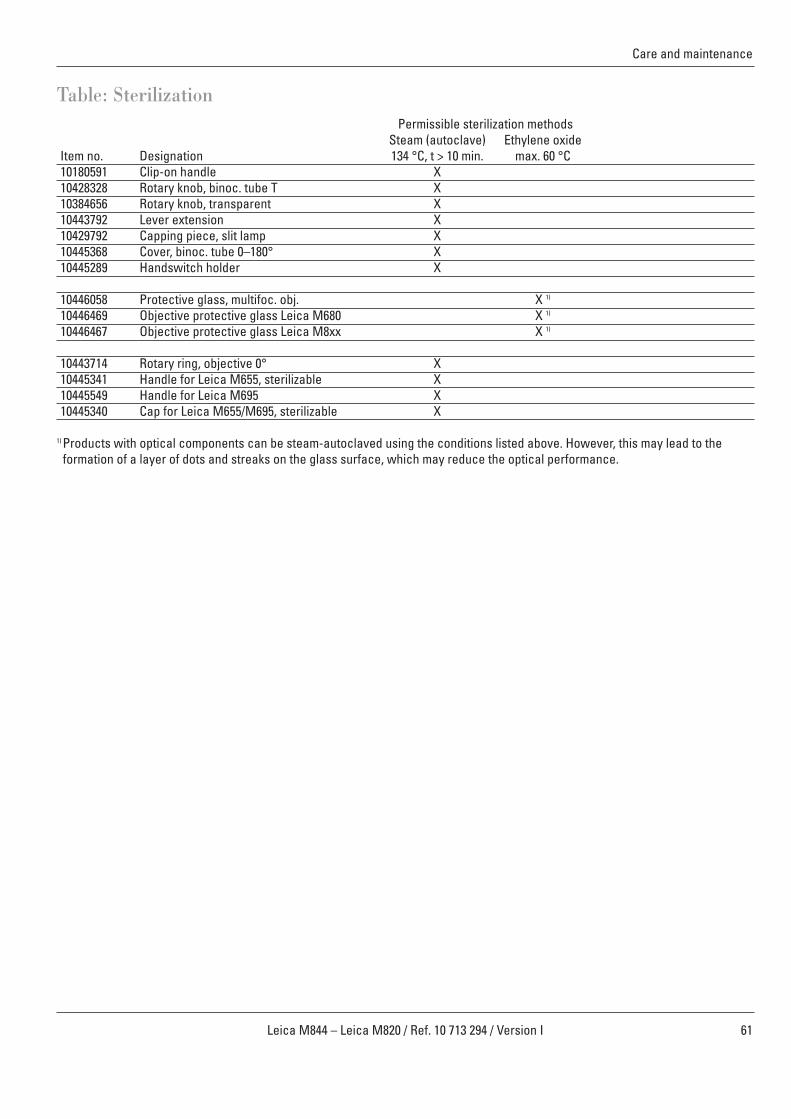
61Leica M844 – Leica M820 / Ref. 10 713 294 / Version I
Care and maintenance
Table: SterilizationPermissible sterilization methods
Steam (autoclave) Ethylene oxideItem no. Designation 134 °C, t > 10 min. max. 60 °C10180591 Clip-on handle X10428328 Rotary knob, binoc. tube T X10384656 Rotary knob, transparent X10443792 Lever extension X10429792 Capping piece, slit lamp X10445368 Cover, binoc. tube 0–180° X10445289 Handswitch holder X
10446058 Protective glass, multifoc. obj. X 1)
10446469 Objective protective glass Leica M680 X 1)
10446467 Objective protective glass Leica M8xx X 1)
10443714 Rotary ring, objective 0° X10445341 Handle for Leica M655, sterilizable X10445549 Handle for Leica M695 X10445340 Cap for Leica M655/M695, sterilizable X
1) Products with optical components can be steam-autoclaved using the conditions listed above. However, this may lead to theformation of a layer of dots and streaks on the glass surface, which may reduce the optical performance.

62 Leica M844 – Leica M820 / Ref. 10 713 294 / Version I
What to do if...?
Fault: The functions cannot be activated with the handswitchor footswitch
Cause 1: A cable connection has loosened.
Cause 2: Assignment entered incorrectly on the control unit.
Microscope
Fault: There is no light in the microscope.Cause 1: A cable connection has loosened.
Cause 2: Quick-change lamp mount not positioned correctly.
Cause 3: Bulb is defective (message "Check Mainlamp 1/2" appears).
Fault remedy:➩Check the power cable.➩Check the handle connections.
Fault remedy:➩Check the assignment of the footswitch/handswitch on the
control unit (see page 43).
Fault remedy:➩Check the electrical connections.➩Check the power cable.
Fault remedy:➩Slide the quick-change lamp mount to the other side
(see page 39).
Fault remedy:➩If the main light fails during the operation, switch to the other
lamp using the quick-change lamp mount.➩After the operation, check the bulbs and replace the defective
bulb (see page 59).
If electrically operated functions do not work properly,always check these points first:• Is the power switch switched on?• Is the power cable attached correctly?• Are all connecting cables attached correctly?
General
63Leica M844 – Leica M820 / Ref. 10 713 294 / Version I
What to do if...?
Fault: There is no OttoFlexTM
II light in the microscope.Cause 1: A filter slide is inserted.
Cause 2: The switch is set to the Slitlamp position.
Cause 3: Bulb is defective
Fault: The image goes out of focus.Cause 1: Eyepieces not seated properly
Cause 2: Dioptric correction is not set correctly.
Fault: Zoom cannot be adjusted electricallyCause 1: Zoom motor has failed.
Fault: Unwanted reflectionsCause 1: The sterile drape produces stray reflections
Fault: The surgical microscope does not move, or requiresundue force.
Cause 1: A cable is jammed.
Cause 2: The transport lock has not been released.
Cause 3: A brake is not released.
Fault remedy:➩Check to see whether a filter slide is inserted; if so, pull it out.
Switch the OttoFlexTM II back on.
Fault remedy:➩Check the position of the Otto Flex/
Slitlamp switch (see page 23) and set it to Otto Flex.
Fault remedy:➩Check the bulbs and replace any that are
defective (see page 59).
Fault remedy:➩Check the seating of the eyepieces and screw them in all the
way if necessary.
Fault remedy:➩Carry out the dioptric correction by following the instructions
exactly (see page 24).
Fault remedy:➩Push and turn the zoom rotary knob to manually adjust the
zoom (see page 13).
Fault remedy:➩Clamp the objective cover of the sterile drape to the objective
with the cover tilted slightly forwards.
Fault remedy:➩Move the jammed cable to another position.Fault remedy:➩Release the transport lock (see page 35).
Fault remedy:➩Contact your Leica representative.

64 Leica M844 – Leica M820 / Ref. 10 713 294 / Version I
What to do if...?
Two-in-One control unitFault: There is no picture in the display
Cause 1: The touch panel is in video mode, but is not receivinga video signal.
Cause 2: A cable connection has loosened.
Cause 3: The display is defective.
Error messages on the control unitFault:
• Check Main Lamp 1• Check Main Lamp 2• Check Slitlamp
Fault: Check Ottoflex
Fault:• Compact Stand Brake Controller not present• Zoom-Lamp Controller not present• Focus-Tilt Controller not present• XY Controller not present• Microscope Device Controller not present
(Command Interface)• Microscope Device Controller not present
(Config Interface)
F40 standFault: The surgical microscope does not move, or requires
undue force. Cause 1: A cable is jammed.
Cause 2: The transport lock has not been released.
Cause 3: A brake is not released.
C40 ceiling mountFault: Leica M844 C40 or Leica M820 C40 rotates.
Fault: The Leica M844 C40 or Leica M820 C40 drifts up or down.
Fault remedy:➩ Switch to control unit mode (see page 40).
Fault remedy:➩ Check to ensure that the cable connections are tight.
Fault remedy:➩ Contact your Leica representative.➩ You can still work with your Leica microscope.
All functions can still be operated using thefootswitch/handswitch.
Fault remedy:➩ Switch to the second lamp using the corresponding
quick-change lamp mount.➩ Replace the defective bulb as soon as possible.
Fault remedy:➩ Replace the defective bulb as soon as possible.
Fault remedy:➩ Contact your Leica representative.
Fault remedy:➩ Move the jammed cable to another position.Fault remedy:➩ Release the transport lock (see page 36).Fault remedy:➩ Contact your Leica representative.
Fault remedy:➩ Contact your Leica representative.➩ Have the adjustment of the suspension checked and
readjusted.
Fault remedy:➩ Contact your Leica representative.➩ Have your Leica service technician slightly brake the
corresponding axis using the built-in drift brakes.

65Leica M844 – Leica M820 / Ref. 10 713 294 / Version I
Fault remedy:➩ Wait approximately 30-45 minutes until the telescope motor
has cooled off.Fault remedy:➩ Check the clamping terminal.➩ Check the plug of the remote control.Fault remedy:➩ Replace the fuse.
Fault remedy:➩ Balance swing arm (see page 34).
Fault remedy:➩ Check the position of the cables, especially in case of
subsequently added video cables.
Fault remedy:➩ Reduce the total weight of the microscope and accessories
Fault remedy:➩ Adjust the articulation brakes so that you can position the
microscope easily (see page 34).
Fault remedy:➩ Optimize the settings for the camera and/or
monitor (see manufacturer's operating instructions).➩ Also refer to page 18.
Fault remedy:➩ Adjust the brightness or replace the filter in the dual
attachment.
Fault remedy:➩ Check the parfocality of the microscope (see page 24).
Fault remedy:➩ Focus precisely, insert graticule if necessary.
What to do if...?
CT40 ceiling mountFault: The Leica CT40 cannot be moved up or down.Cause 1: The Leica CT40 is protected by a temperature switch
that switches off in case of overheating.
Cause 2: Poor plug contact.
Cause 3: Customer's fuse defective.
F19 standFault: The swing arm moves up/down by itself.
Cause 1: Swing arm is not balanced.
Cause 2: Bad cabling.
Fault: The swing arm sinks even at the highest level of the balancing scale.
Cause: Maximum load of optics carrier exceeded.
Fault: The microscope is difficult to position.Cause: Articulation brakes are too tightened.
TV, photographyFault: The image on the monitor is too dark.Cause 1: The video camera and/or monitor are not set
correctly.
Cause 2: Filter in dual attachment is set incorrectly.
Fault: Photos are blurry.Cause 1: Parfocality of microscope has not been adjusted.
Cause 2: Object is out of focus.

66 Leica M844 – Leica M820 / Ref. 10 713 294 / Version I
Technical data
Microscope
Leica QuadZoom™ Optical system with four beam paths:100% stereopsis for surgeon andassistant (Leica M844 only)
Leica OptiChrome™ High-performance optics for highcontrast, brilliant colors, crisp imagedefinition, and outstanding resolution
Magnification changer 6:1 range, motorizedField diameter 7 mm to 80 mmWorking distances WD 175 mm, 200 mm, 225 mmFocusing Motorized, 54 mm,
with automatic resetLeica ErgonOptic™ Binocular tube 10° to 50°,
Low and UltraLowTM
II; variable 0-180°; variable 30-150°
Eyepieces Wide-field eyepieces for spectaclewearers 8.33×, 10×, 12.5*×
Objectives Leica OptiChromeTM
WD 175 mm/f = 200 mmWD 200 mm/f = 225 mmWD 225 mm/f = 250 mmWD: working distancef: focal length
X/Y coupling Motorized, 50 mm×50 mm, with automatic reset
Tilt drive Motorized, +15°/–50°Remote control 12-function footswitch with
long or cross pedals, 12-function handswitch,16-function footswitch with cross pedals
Weight 28.3 kg (with accessories andXY unit)
Lamps
Main light Integrated illumination concept for intense, uniform red reflex
Leica OttoFlexTM II Illuminator module for increasing red reflex, decreasing stray lightthrough the sclera and increasingimage contrast. Variable field diameter from 4 mm - 35 mm at WD 200 mmPrecision-formed halogen bulb 12 V/50 W
Quick-change lamp mount With two precision-formed (main light only) halogen bulbs 12 V/50 WFilters IR barrier filter and UV barrier filter
(GG420), integrated
Accessories
0° assistant’s 100% stereopsis at the same attachment magnification,
integrated fine focus, rotary ring for binocular tube(±15°),documentation port
Double wing for 3 simultaneous observersTV/photo Leica 2D video systems
Leica D2D digital video system Leica zoom video adapterf = 35-100 mm Photo/TV dual attachment f = 60/ 85/ 107 mm for TV f = 250/ 350 mm for 35 mm cameraTV tube f= 107 mm Phototube f= 250/350 mm
Wide-angle observation BIOM*, EIBOS*systemInverter AVI*, SDI*, OIVSL*, ROLS*Lasers Adapters for installation are
available from laser manufacturerSlit lamp Motorized, ±23°,
slit width 0.01-15 mm, slit length 3-15 mm, 180° revolving, quick-changelamp mount
Asepsis All operating elements can besterilized, sterile drapes are available
* Accessories from third-partymanufacturers

67Leica M844 – Leica M820 / Ref. 10 713 294 / Version I
Technical data
Electrical data
Power socketF40 floor stand Central on the horizontal arm
100–240 VAC (±10%), 50/60 HzF19 floor stand Central on the horizontal arm
100–240 VAC (±10%), 50/60 HzCT40 ceiling mount Terminal strip on the ceiling
100/120 VAC, 220/240 VAC (±10%), 50/60 Hz
C40 ceiling mount Terminal block on the ceiling 100/120 VAC, 220/240 VAC (±10%), 50/60 Hz
Fuse 2× 6.3 A, time-lag
Power consumptionLeica M844 / M820 F40 400 VALeica M844 / M820 F19 300 VALeica M844 / M820 C40 400 VA (without ceiling mount)Leica Ceiling Mount 400 VA (ceiling mount only)Leica M844 / M820 CT40 (120V ~60 Hz) 1500 VA
(whole system incl. telescope)Leica M844 / M820 CT 40 (230V ~50 Hz) 1400 VA
(whole system incl. telescope)
Protection class Class 1
Auxiliary power socket
Max. permitted power consumption of the secondary device: 100 VAMax. permitted ground leakage current of the secondary device: 200 µA at 110 V
300 µA at 230 VRequired conformity of the secondary device: EN 60601-1 (Europe)
UL 60601-1 (USA)If the device does not conform, it must be connected via anisolating transformer.If the ground leakage current exceeds the permitted limit value,the following measures are required:• Device does not conform to EN 60601-1 (Europe) / UL 60601-1
(USA): Connection via isolating transformer.• Device conforms to EN 60601-1 (Europe) / UL 60601-1 (USA):
Connection via potential equalization or isolating transformer.
Optical data
With UltraLowTM
II binocular tube
ObjectiveLeica OptiChrome™
WD = 175 mm/f = 200 mmEyepiece
Total magnification Field of view(∅ mm)
8.33× 3.4× – 20.4× 53.9 – 9.0
10× 4.1× – 24.5× 51.4 – 8.6
12.5× 5.1× – 30.7× 41.6 – 6.9
ObjectiveLeica OptiChrome™
WD = 200 mm/f = 225 mmEyepiece
Total magnification Field of view(∅ mm)
8.33× 3.0× – 18.2× 60.6 – 10.1
10× 3.6× – 21.8× 57.8 – 9.6
12.5× 4.5× – 27.3× 46.8 – 7.8
ObjectiveLeica OptiChrome™
WD = 225 mm/f = 250 mmEyepiece
Total magnification Field of view(∅ mm)
8.33× 2.7× – 16.3× 67.3 – 11.2
10× 3.3× – 19.6× 64.3 – 10.7
12.5× 4.1× – 24.5× 52.0 – 8.7

68 Leica M844 – Leica M820 / Ref. 10 713 294 / Version I
Technical data
Stands/ceiling mounts
F40 floor standCastors 4x 82.5 mmWeight Base: 174 kg
Column: 83 kg Total weight Approx. 330 kg with max. loadBrakes Four electromagnetic
brakes, operated by turning the handles,one stop lever for verticalmovement
Load Max. 12.2 kg frommicroscope/dovetail ring interface
Space requirement: Foot: 637 x 637 mmmin. height in rest position: 1949 mm
Range Extension 1492 mm max.Stroke 846 mmBalancing via gas springTurning range Axis 1 (near column): ±170°
Axis 2 (in the middle): +150°/-170°Axis 3 (over XY unit): ±270°
F19 floor standCastors 4x82,5 mm Weight of base 174 kg
Column: 20 kgTotal weight Approx. 270 kg with max. load Brakes 4 mechanical articulation brakes,
locking lever for vertical movement
Load Swing arm: Max 11.5 kg frommicroscope dovetail ring
Space requirement Foot: 637 x 637 mmmin. height in rest position: 1949 mm
Range Extension 1305 mm max.Stroke 652 mmBalancing via gas springTurning range Axis 1 (near column): 360°
Axis 2 (in the middle): ± 170°Axis 3 (over XY unit): ± 270°
C40 ceiling mountCeiling attachment Max. distance from concrete ceil-
ing to intermediate ceiling: 1200 mmAttachment to concrete shellconstruction ceiling: 470 mm hole circle 6 x M24 FHA 24/0/50Bor FHA 24/0/150B
Weight Ceiling mount: Max. 90 kg (at max. tube length) Normally approx. 85 kg Swing arm 44 kg
Brakes Swing arm:Four electromagnetic brakes, operated by turning the handles, one stop lever for vertical movement
Load Ceiling mount: Max. 85 kgSwing arm: Max. 12.2 kg frommicroscope/dovetail ringinterface
Range Ceiling mount extension: 957 mmSwing arm extension: 1492 mm
Travel range Ceiling mount: ±300 mm Swing arm: 846 mm
Balancing via gas springTurning range Ceiling mount: 330°Swing arm: Axis 1 (ceiling mount): ±90°
Axis 2 (in the middle): ±135°Axis 3 (over XY unit): ±270°

69Leica M844 – Leica M820 / Ref. 10 713 294 / Version I
Technical data
CT40 ceiling mountCeiling attachment Max. distance from concrete
ceiling to intermediate ceiling: 1200 mmAttachment to concrete shellconstruction ceiling: 440 mm hole circle 4 x M12 HSLB M12/15
Weight Swing arm: 44 kgTotal weight Approx. 146 kgBrakes Swing arm:
Four electromagnetic brakes, operated by turning the handles,one stop lever for vertical movement
Load Swing arm: Max. 12.2 kg frommicroscope/dovetail ringinterface
Range Extension 1492 mm max.Travel range Telescopic unit: 500 mm
Swing arm: 846 mmBalancing via gas springTurning range: Axis 1 (ceiling mount): ±90°
Axis 2 (in the middle): ±135°Axis 3 (over XY unit): ±270°
Ambient conditions
In use +10 °C to +40 °C+50 °F to +104 °F30% to 95% rel. humidity500 mbar to 1060 mbar atmospheric pressure
Storage –40 °C to +70 °C–40 °F to +158 °F10% to 100% rel. humidity500 mbar to 1060 mbar atmospheric pressure
Standards fulfilled
Conformity • Medical devices directive93/42/EEC Classification: Class I,in compliance with appendix IX,rule 1, with reference to rule 12 ofthe directive.
• Medical electrical equipment,Part 1: General requirements forsafety IEC 60601-1; EN 60601-1;UL60601-1; CAN/CSA-C22.2 NO.601.1-M90
• Electromagnetic compatibility IEC60601-1-2; EN 60601-1-2The Surgical Division, withinLeica Microsystems (Schweiz)AG, has the management systemcertificate for the internationalstandards ISO 9001:2000 / ISO13485:2003 and ISO 14001:2004relating to quality management,quality assurance andenvironmental management.
Limitations of use
The Leica M820 F40, Leica M820 C40, Leica M820 CT40, LeicaM820 F19, Leica M844 F40, Leica M844 F19 and Leica M844 CT40surgical microscopes may be used only in closed rooms andmust be placed on a solid floor or attached to a strong ceiling orwall.
For the Leica M820 F40 and Leica M844 F40, drift effectsmust be taken into account on floors which slant >0.3°.
.

70 Leica M844 – Leica M820 / Ref. 10 713 294 / Version I
Technical data
Dimensioning drawing (mm) for Leica M820 F40 and Leica M844 F40

71Leica M844 – Leica M820 / Ref. 10 713 294 / Version I
Technical data
Dimensioning drawing (mm) for Leica M820 and Leica M844 C40
Axes of rotation
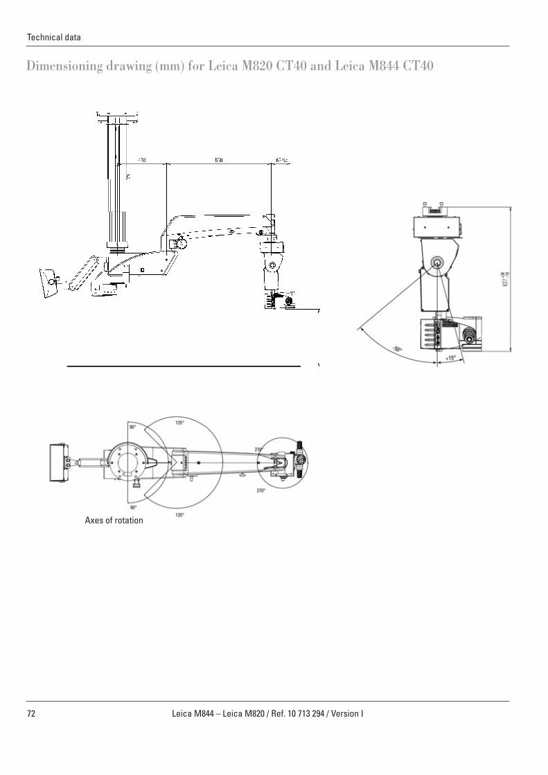
72 Leica M844 – Leica M820 / Ref. 10 713 294 / Version I
Technical data
Dimensioning drawing (mm) for Leica M820 CT40 and Leica M844 CT40
Axes of rotation

73Leica M844 – Leica M820 / Ref. 10 713 294 / Version I
Technical data
Dimensioning drawing (mm) for Leica M820 F19 and Leica M844 F19

www.leica-microsystems.com
Leica Microsystems operates globally in four divi sions, where we rank with the market leaders.
Life Science DivisionThe Leica Microsystems Life Science Division supports the imaging needs of the scientifi c community with advanced innovation and technical expertise for the visualization, measurement, and analysis of microstructures. Our strong focus on understanding scientifi c applications puts Leica Microsystems’ customers at the leading edge of science.
Industry DivisionThe Leica Microsystems Industry Division’s focus is to support customers’ pursuit of the highest quality end result. Leica Microsystems provide the best and most innovative imaging systems to see, measure, and analyze the micro-structures in routine and research industrial applications, materials science, quality control, forensic science inves-tigation, and educational applications.
Biosystems DivisionThe Leica Microsystems Biosystems Division brings his-topathology labs and researchers the highest-quality, most comprehensive product range. From patient to pa-thologist, the range includes the ideal product for each histology step and high-productivity workfl ow solutions for the entire lab. With complete histology systems fea-turing innovative automation and Novocastra™ reagents, Leica Microsystems creates better patient care through rapid turnaround, diagnostic confi dence, and close cus-tomer collaboration.
Surgical DivisionThe Leica Microsystems Surgical Division’s focus is to partner with and support surgeons and their care of pa-tients with the highest-quality, most innovative surgi cal microscope technology today and into the future.
“With the user, for the user”Leica Microsystems
The statement by Ernst Leitz in 1907, “with the user, for the user,” describes the fruitful collaboration with end users and driving force of innovation at Leica Microsystems. We have developed fi ve brand values to live up to this tradition: Pioneering, High-end Quality, Team Spirit, Dedication to Science, and Continuous Improvement. For us, living up to these values means: Living up to Life.
Active worldwide Australia: North Ryde Tel. +61 2 8870 3500 Fax +61 2 9878 1055
Austria: Vienna Tel. +43 1 486 80 50 0 Fax +43 1 486 80 50 30
Belgium: Groot Bijgaarden Tel. +32 2 790 98 50 Fax +32 2 790 98 68
Canada: Richmond Hill/Ontario Tel. +1 905 762 2000 Fax +1 905 762 8937
Denmark: Herlev Tel. +45 4454 0101 Fax +45 4454 0111
France: Rueil-Malmaison Tel. +33 1 47 32 85 85 Fax +33 1 47 32 85 86
Germany: Wetzlar Tel. +49 64 41 29 40 00 Fax +49 64 41 29 41 55
Italy: Milan Tel. +39 02 574 861 Fax +39 02 574 03392
Japan: Tokyo Tel. +81 3 5421 2800 Fax +81 3 5421 2896
Korea: Seoul Tel. +82 2 514 65 43 Fax +82 2 514 65 48
Netherlands: Rijswijk Tel. +31 70 4132 100 Fax +31 70 4132 109
People’s Rep. of China: Hong Kong Tel. +852 2564 6699 Fax +852 2564 4163
Portugal: Lisbon Tel. +351 21 388 9112 Fax +351 21 385 4668
Singapore Tel. +65 6779 7823 Fax +65 6773 0628
Spain: Barcelona Tel. +34 93 494 95 30 Fax +34 93 494 95 32
Sweden: Kista Tel. +46 8 625 45 45 Fax +46 8 625 45 10
Switzerland: Heerbrugg Tel. +41 71 726 34 34 Fax +41 71 726 34 44
United Kingdom: Milton Keynes Tel. +44 1908 246 246 Fax +44 1908 609 992
USA: Bannockburn/lllinois Tel. +1 847 405 0123 Fax +1 847 405 0164
and representatives in more than 100 countries
10 7
13 2
94en
/I• ©
Lei
ca M
icro
syst
ems
(Sch
wei
z) A
G •
CH-9
435
Hee
rbru
gg, 2
009
• Prin
ted
in S
witz
erla
nd –
IV.2
009
– RD
V –
Illus
trat
ions
, des
crip
tions
and
tech
nica
l dat
a ar
e no
t bin
ding
and
may
be
chan
ged
with
out n
otic
e.