lego beyond toys - christoph bartneck
TRANSCRIPT

1
LEGOBEYOND TOYS
Wireless sensor extension pack
Tom Frissens040915
December 2008
Faculty of Industrial DesignEindhoven University of Technology

2
TABLE OF CONTENT
CLASS INTRODUCTION PAGE 3
IDEA INTRODUCTION PAGE 4
WIRELESS TECHNOLOGY PAGE 5
LEARNING XBEE PAGE 6
USING XBEE PAGE 7
SENSOR DESIGN AND MECHANICS PAGE 12

3
CLA
SS
INT
RO
DU
CT
ION
This master class was done in eight weeks, spread over one semester. The over-all theme was “LEGO beyond toys”, which meant looking beyond the play factor of LEGO and see how the NXT platform could be used to apply theories like reinforcement learning and pattern recognition for example. Besides the software possibilities, attention was paid to hardware by looking closely to some mechanical principles and specific LEGO properties. Next to these lectures the over-all assignment was to create an extension for the LEGO Mindstorms set.This report will focus on the development of this extension pack.

4
IDEA INTRODUCTION
My LEGO Mindstorms extension idea came from a couple directions, first I wanted to make something which would be ‘plug and play’, so you would not need any difficult settings and programming for it to be useable. Secondly it should fit the current LEGO designs, meaning it shares the visual properties and mechanical construction as the already existing Mindstorm sensors. Finally I looked at interesting hardware I was still unexperienced with and which offers great possibilities for future use.
Putting these goals and ideas together, I was going to look at possibilities on how to create an extension pack which would create a wireless bridge between sensors and the NXT.Such extension could have a wide field of application, for example an awareness system. For such system I imagined a distance or light sensor which would detect if a door opens, so a robot can react on this. Other possibilities can be seen in moveable objects of which the NXT is not part, because of its weight for example.
Putting it in an other way, a wireless sensors cannot be done with the current hardware available. With the many imaginable possibilities, developing such extension would be a valuable contribution to the LEGO MIndstorms community and would offer great learning experiences.
Below is the scheme I made during the start of this project and shows where my extension should be put and how it should be connected.
NXT
Sensor
Wireless sensor extension pack for LEGO Mindstorm
XBee
XBee
Battery

5
WIR
ELE
SS
TE
CH
NO
LOG
Y
Building a wireless bridge between sensors and the NXT would at first need some insights in how the NXT and the different sensors work. For this I used the hardware developer kit, which is available from the LEGO Mindstorms website. This developer kit features in-depth information and instructions about how each different sensor works, which connections are required and what components are used.
From this I learned that there are three kind of sensors:active sensors; these sensors are the old sensors supplied with the RCX and through a special timing scheme, the NXT enables backward compatibility with these sensors.passive sensors; these sensors do not need special power/measurement timing and are the new Mindstorms sensors supplied with the NXT.digital sensors; These sensors use I2C communication and an external microcontroller built in the sensor.
Looking at how these different sensors work I was able to learn that I would need to wireless transfer up to two analog signals.
The NXT already features Bluetooth, the first solution in making sensors wireless was therefore seen in developing a brick which connects to the NXT through this Bluetooth connection. This would require the use of a microcontroller, since Bluetooth modules do not enable direct input and output. The biggest problem with using Bluetooth was that it would limit the range of the sensor to a maximum of ten meters. Looking at the possibilities, this would not be the optimal solution since there will be projects in which larger distances are preferred.
An other solution could be seen in the use of XBee modules, these small RF transceivers enable direct input and output pins, which enables a 1 on 1 mapping between the transmitter input and the receiver output pins. This in combination with a range of up to 1.6 kilometers if you use the PRO version looked perfect for my application.Because I was able to get easy access to XBee modules, I could immediately start experimenting without any long delivery dates and therefore the decision was made to use XBee modules for the wireless communication.

6
LEARNING XBEE
An XBEE module features 20 pins of which nine can be used for digital input or output, seven for analog input and two for PWM output. Before using the XBee, the modules have to be programmed in such a way that they accept data from each other and that they are communicating on the same channel. This is done by using special software which is provided by the manufacturer. It took me some time to figure everything out, but for a first demonstrator I was able to control a led by using either a digital input pin with a switch or an analog pin with a potentiometer to fade the led.
Basically the following configurations were made to the XBee modules:
Input module:ATID - 1234 (channel ID)ATMY - 2 (own identification number)ATDL - 1 (destination number)ATD0 - 2 (analog input)ATD1 - 3 (digital input)ATIR - 14 (20 milliseconds sample rate)ATIT - 5 (5 samples before transmitting)
Output module:ATID - 1234 (channel ID)ATMY - 1 (own identification number)ATDL - 2 (destination number)ATP0 - 2 (pwm output enabled)ATD1 - 5 (digital output high)ATIU - 1 (enable i/o output)ATIA - 2 (i/o input address is 2)
7
US
ING
XB
EE
Further developments featured connecting the NXT sensors to the XBee modules in order to read and send data. Before I was able to do this I needed some more detailed information in how to power each specific sensor and what signal they would output.
Using the hardware developer kit, I was able to make the following list:- Light Sensor; pin 1 should be the 9 Volt supply power, pin 2 and 3 are the ground connections, pin 4 is the 5 Volt supply power, pin 5 is the analog output value between 0 and 5 Volt, pin 6 remains unconnected
- Touch Sensor; pin 1 is the 9 Volt supply, which is connected to the ground pins 2 and 3 when pressed.
- Sound Sensor; pin 1 is the 9 Volt supply, and pin 2 and 3 are the ground pins again. Pin 4 is the 5 Volt supply and pin 5 and 6 are analog pins which give a value between 0 and 5 Volt.
- Ultrasonic Sensor; pin 1 is the 9 Volt supply, pin 2 and 3 are ground pins and pin 4 is the 5 Volt supply pin. pin 5 and 6 are two analog pins, which are used for I2C connection and pin 5 is therefore the data line and pin 6 the clock line of this connection.
Based on this information I was able to get the touch sensor working with my previous scheme which switched a led based on input on an other XBee.A problem I had to overcome was that the LEGO sensors operate on 9 and 5 Volt and that they output 0 to 5 Volt, while the XBee operates on 3.3 Volt. Using a 9 Volt power supply and two voltage resistors solved the power supply problem.
The output power problem was a little more complicated, since the sensors would give an output voltage from 0 to 5 Volt and the XBee only accepts 0 to 3.3 Volt analog input. Looking for solutions I came across a simple electronic scheme called a voltage divider (displayed on the left). R
2
With the formula Vout
= Vin
I was able to R
1 - R
2
calculate that I would need to set R1 to 5.1K Ohm if I would set R2 to 10K Ohm.
A bigger problem I ran into when trying to forward the received sensor data from the receiver XBee to the NXT was that the XBee outputs a PWM signal with a maximum of 3.3 Volt. A DC to DC circuit was needed, but because I had an Arduino mini laying around which is already able to output a voltage between 0 and 5 Volts I would be able to build this in to get my system working and even enable I2C sensors to be connected.

8
After the decision was made to implement Arduino in my extension, I was able to easily read sensor data from all the passive sensors, even without any voltage divider circuits because the Arduino accepts inputs up to 5 Volts. The way the XBee was used changed since I would use the “RX” and “TX” ports to Receive and Transmit data between both Arduinos.
Since I was already able to read the passive sensors I started with the active sensor which is implemented in the Mindstorms set, the ultrasonic sound sensor.Up to this point I neglected the Ultrasonic sensor since it used I2C and research learned that an XBee is not able to transmit this signal since it requires two lines which have to work parallel. An XBee sends data in one array, meaning that the signal would not be received simultaneous and would therefore be useless.Arduinos are able to communicate with I2C sensors with a special library called “Wire.h”. Looking for ways to read the sensor data from the ultrasonic sound sensor using I2C I learned that there are a couple of commands you are able to send. From the JAVA library I was able to find out the way the JAVA code requests data from the ultrasonic sound sensor:
Tracking this code further lead to an other JAVA class called I2CSensor, which used the following code to get the actual data:
/** * Return distance of object. * * @return distance or 255 if no object in range */ public int getDistance() { int ret = getData(0x42, buf, 1); return (ret == 0 ? (buf[0] & 0xff) : 255); }

9
/** * Executes an I2C read transaction and waits for the result. * * @param register I2C register, e.g 0x41 * @param buf Buffer to return data * @param len Length of the return data * @return status zero=success, non-zero=failure */ public int getData(int register, byte [] buf, int len) { int ret = port.i2cStart(address, register, len, buf, len, 0); if (ret != 0) return ret; while (port.i2cBusy() != 0) { Thread.yield(); } return 0; }
#include <Wire.h>
void setup() { Serial.start(9600); //initialize a serial port to read data}
void loop() { Wire.beginTransmission(0x02); //begin transmission on address 1 Wire.requestFrom(0x42,1); //request one byte on address Serial.println(int(Wire.receive())); //print the received data Wire.endTransmission(); //end the transmission}
Translating both findings to Arduino code should look something like this:
Unfortunately I was not able to read any sensor data this way and although I have tried many other possibilities I was not able to get this working before the deadline of this report. This part of my development has therefore be considered as work in progress and should be working during the exhibition which will take place in January.

10
Previously I told that I introduced an Arduino because of the communication with the NXT and because I would be able to read I2C sensors. I already explained my findings of how to read sensor signals from the ultrasonic I2C sensor. I will now briefly go into the part which communicates with the NXT.
My thanks here goes out to an other participant of the Techno Class, Martijn ten Bhomer. He developed a protocol to enable the communication between the NXT and an Arduino. Basically the JAVA code for communicating with the Arduino uses a six step process:
- Step 1: start an I2C connection with the Arduino, for this you have to define an address, which I set in my case to 123.- Step 2: This is where the actual protocol begins and at this step there are readings done every 10 milliseconds to decide what kind of data there is going to be send.- Step 3: pause 30 milliseconds to indicate to the Arduino that the datatype has been transmitted- Step 4: read the sensor to receive a confirmation of the datatype- Step 5: read the sensor to receive byte 35 (character #) to indicate that the data transfer starts- Step 6: receive a byte array with the actual data

11
Next to reading sensor values I have been experimenting with driving motors using XBee. For this I used the L293D motor driver IC and I was quickly able to control the motor speed using an Arduino with which I simulated the 0 to 3.3 output voltage from the XBee. Difficulty with this circuit was again that I was only able to apply voltage up to 3.3 Volt to the motor driver IC and therefore the motors would never be able to run at full speed.Just like discussed previously, this scheme would require a DC to DC circuit. I solved this problem by implementing an Arduino, which enables full 0 to 5 Volt PWM output.
A new problem occurred at the sender side of the communication, because the NXT changes the current (amperage) to regulate the motor speed. To measure the current and transform it to a signal I could use as analog input for the XBee, a current to voltage circuit had to be made.With the formula V = I x R I was easily able to calculate that I would need a 5 Ohm resistor to measure the current changes which in the NXT go from 0 to a maximum of 1 Amps.
The theory for driving motors wireless was all there, but because making the sensors wireless would offer more possibilities I focused on making the I2C sensors work.

12
DESIGN & MECHANICS
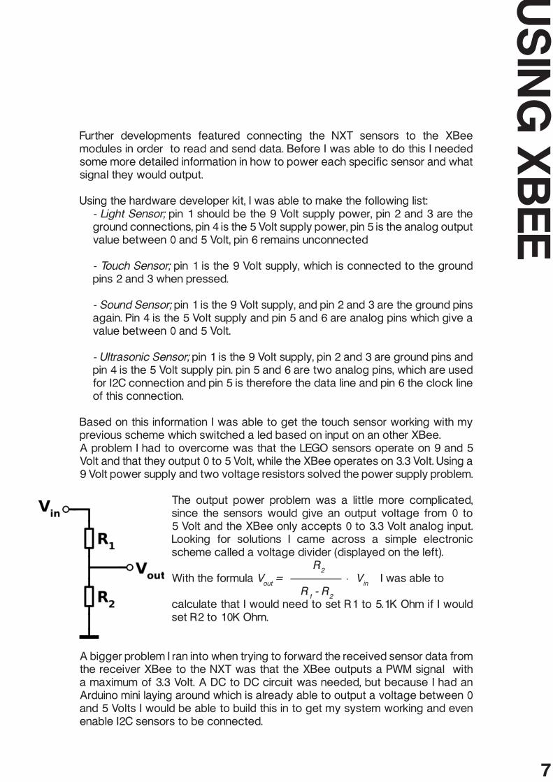
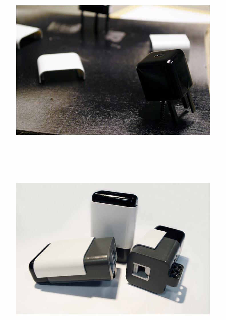
Simultaneous to my electronic developments, I worked on the design of my sensor. I wanted it to look as finished as possible, meaning I was going to 3D print the parts.
Because I was very interested in how the sensor of the Mindstorms set were mechanically put together, I forced one open to learn from it and to enable myself to design my own sensor in the same way.
Interesting to see was the way the electronics can easily be slid into the base casing and how the top cover locks it into place. The sensor casing is closed using snaps in three places, one on the bottom and two on the sides. Since the top cover covers these side snaps, it is very hard to open the sensor.
Based on these observations I started modeling my own casings, starting with the base. The base featured the LEGO connector holes, which after careful measurements were reproduced.
After the 3D print was finished, I cleaned and sanded the parts after which they were spraypainted.The final results are very nice casings which match the current sensors, but because I used the exact measurements of the LEGO holes, the pins require some force to stick them in and get them out again. This has to do with the tolerances and material properties of LEGO. LEGO is made of a special ABS which has some flexibility, but the fact that I spray painted my casings meant I added a very small extra layer to the inside of the holes causing them to be smaller and thus make the fitting even more tight.What I should have done is make the holes a little bit bigger to enable an extra layer of paint, but still enable the pins to go in and out smoothly.
Pictures of the process and technical drawings are displayed on the next pages.
DESIGN & MECHANICS

74.90
44.25
33.80

44,55
31,50
65
65
31.50
44.55

16
REFERENCES
http://mindstorms.lego.com/Overview/nxtreme.aspx
http://www.bartneck.de/work/education/masterClassLego/javaInstallNXT/index.html
http://www.daimi.au.dk/~u064552/esea4project/omnidirectional/java/lejos/nxt/UltrasonicSensor.java
http://www.faludi.com/2006/12/03/xbee-direct-io-with-adc/
http://forums.nxtasy.org/index.php?showtopic=2092
http://www.neufeld.newton.ks.us/electronics/?p=241
http://hsrc.static.net/Research/NXT%20I2C%20Communication/
http://tau.ac.il/~stoledo/lego/i2c-8574-l272/
http://letsmakerobots.com/node/2074?page=1
http://wiring.org.co/reference/libraries/Wire/index.html