legacy platinum cfr industrial battery charger · 2012-03-06 · 2 safety instructions warning this...
TRANSCRIPT

Installation, Operating & Service Instructions
Legacy Platinum CFR
Industrial Battery Charger
Douglas Battery Manufacturing Company500 Battery Drive Winston-Salem, North Carolina 27107
1-800-DOUGLAS http://www.douglasbattery.com
M-0375 Eff. 9-00
1
TABLE OF CONTENTS
SAFETY INSTRUCTIONS ................................................................................................ 2
RECEIPT AND INSPECTION .......................................................................................... 3
DESCRIPTION OF OPERATION...................................................................................... 3
CONTROL FEATURES..................................................................................................... 4
INSTALLATION................................................................................................................. 6
OPERATING PROCEDURE ............................................................................................. 9
CHARGER CABINETS ..................................................................................................... 12
SERVICING ...................................................................................................................... 13
START & FINISH RATE ADJUSTMENT........................................................................... 16
TROUBLESHOOTING GUIDE.......................................................................................... 17
REPLACEMENT PARTS ................................................................................................. 20
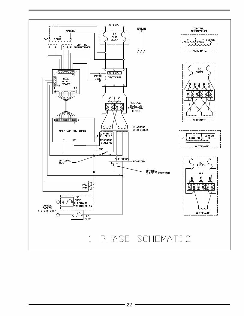
SCHEMATICS................................................................................................................... 22
MAINTENANCE RECORD................................................................................................ 24
2
SAFETY INSTRUCTIONS
WARNING THIS CHARGER CONTAINS LETHAL VOLTAGE LEVELS.
INSTALLATION AND SERVICING MUST BE PERFORMED BY QUALIFIED PERSONNEL.
IMPORTANT: SAVE THESE INSTRUCTIONS! READ AND FOLLOW ALL INSTRUCTIONS BEFORE INSTALLING, OPERATING, OR SERVICING CHARGER. ANY DEVIATION CAN CAUSE SERIOUS AND PERMANENT DAMAGE. FAILURE TO
FOLLOW THE INSTRUCTIONS VOIDS THE WARRANTY. 1. Install and ground the charger in accordance with the National Electric Code or your local electric
code. Failure to properly ground the charger could result in a fatal electric shock. 2. To reduce the risk of fire, install chargers on a floor of non-combustible material such as stone,
brick, or grounded metal. 3. This charger has been designed to charge flooded and absorbed electrolyte (sealed) lead-acid
batteries. It should not be used be used for charging other types of flooded batteries or gelled electrolyte batteries.
4. Connect only batteries of the same number of cells and ampere-hour rating as listed on the charger
nameplate. Damage to the battery could occur, particularly if the battery has fewer cells than the rating of the charger
5. Do not touch uninsulated parts of the output connector or the battery terminals. A possibility of
serious electrical shock exists. 6. During charge, batteries produce hydrogen gas which can explode if ignited. Never smoke, use an
open flame, or create sparks in the vicinity of the battery. Ventilate well when the battery is in an enclosed space.
7. Do not connect or disconnect the battery plug while the charger is on. Doing so will cause arcing
and burning of the connector resulting in charger damage or battery explosion. 8. Lead-acid batteries contain sulfuric acid which causes burns. Use proper personnel protective
equipment. Do not get in eyes, on skin, or on clothing. In cases of contact with eyes, flush immediately with clean water for 15 minutes. Seek medical attention immediately.
9. Do not operate the charger with the door open or with any panels removed. De-energize all AC and
DC power connections before servicing the charger. 10. The charger is not for outdoor use. Operating conditions should be 0° to 104° F and less than 70%
relative humidity. Do not expose the charger to water spray, rain or snow. 11. Do not operate the charger with damaged cables, including cables with exposed conductors or
damaged connectors. Replaced damaged cables before operation. 12. Do not operate the charger if it has been dropped, received a sharp blow, or otherwise damaged in
any way. Call your Douglas service representative. 13. Do not use or store flammable or combustible materials within 3 feet of any charger.
3
RECEIPT AND INSPECTION Upon receipt of the charger the information on the shipping carton should be checked against your order. Any discrepancies should be reported to the nearest authorized representative. Whenever possible, move the charger to the installation site before uncrating. All chargers can be handled with a lift truck by inserting the forks under the bottom of the charger. Remove the carton and inspect the charger for damage. If there is any damage, save the carton for inspection and notify the carrier immediately. Check the nameplate & labels against your order & specifications. Any discrepancies should be reported immediately to the nearest authorized Douglas Battery representative.
DESCRIPTION OF OPERATION LEGACY PLATINUM Industrial Battery Chargers are full wave, silicon rectified, pulse enhanced, ferroresonant chargers. Charging current and voltage are controlled by the control circuit. This charger is capable of charging ABSORBED ELECTROLYTE VRLA and FLOODED Lead Acid batteries. This charger is not to be used to charge GELLED electrolyte batteries. A solid state, pre-programmed microcomputer provides total control of the charge cycle, preventing both undercharging and overcharging. The microcomputer incorporates built-in fault detection to ensure correct battery connection and smooth operation. The charge is terminated automatically when the control determines that the battery is fully charged. The charger’s microprocessor maintains the output current at 18A /100 amp hrs until the battery voltage reaches 2.235V/cell. When 2.235V/cell is reached the battery voltage increases while the charging current is decreased to maintain the constant power condition until the gassing voltage is reached. Once the gassing voltage is reached, the charger maintains the battery voltage and allows the charging current to slowly decrease until it reaches the finish current value. When the current reaches the finish current the charger again returns to a constant current mode until dv/dt termination or time termination.
4
CONTROL FEATURES 1. Automatic five second delayed start upon connection of a proper sized battery in good condition. 2. Battery voltage sensing determines if there is a proper sized battery connected to the charger. This
prevents charging if there is a bad battery, no battery connected, bad battery to charger connection or battery voltage and charger mismatch.
3. Battery voltage and current are continuously monitored and controlled. 4. Automatic dv/dt charge termination. 5. Negative battery slope termination to prevent overcharge/thermal runaway. 6. Automatic 24 hour "REFRESH" charge adds a top off charge to a fully charged battery. The charger
will start a “refresh” charge 24 hours after a normal charge complete has been reached, assuming that the battery was not disconnected during that time.
7. Back-up Timers prevent extended charging of a damaged battery. The first timer starts at the
beginning of the charge cycle and runs for 9 hours. If the battery has not reached the gassing point the charger will shutdown. The second timer starts at the gassing point and runs 6 hours for flooded batteries and 4.5 hrs for sealed batteries. Consult section 5.7 of this manual. If the charger has not completed its cycle by then it will shutdown.
8. Automatic Shutdown Lock-out will not allow a charge to start after a manual or problem shutdown
occurs. Automatic Shutdown Lock-out is cleared after the "Shutdown" battery is disconnected. This allows a charge to begin upon connection of a proper sized battery.
9. Manual STOP switch - Will stop the charger from charging. The display will indicate “OFF” until the
battery is disconnected. When pressed with no battery connected, displays the delay start setting. 10. One to nine hour programmable delayed start thumbwheel switch. This rotary switch can be set
from 0 to 9 hours to delay the start of charge. 11. Equalize switch - The switch when depressed will turn on and off the three hour additional
equalizing charge. When the equalize function is turned on an “E” will be displayed in the left most digit of the display and the CHARGE COMPLETE led will flash on for 1/2 second and then off for 3 1/2 seconds until the charger goes into the equalize mode. The “E” will flash during the actual equalize charge cycle.
12. Refresh mode - When the CHARGING and 80% LED’s light continuously and the CHARGE
COMPLETE led is flashing the charger is in the refresh mode. The refresh cycle is an additional charge at the finish rate current. This added charge period will start when the charger is left connected to a battery for 24 hrs after a normal charge cycle is complete. The charger will automatically charge at the finish rate current until dv/dt is detected or until the ceiling voltage limit is reached.
5
13. Automatic shutdown occurs for any of the following seven failure conditions. The SHUTDOWN led will flash when a shutdown occurs.. a) Fault code “Lo U” - Low volts per cell - the battery voltage is less than 1.5 vpc. The charger will
not be “locked off”. The charger will automatically start charging when the battery voltage is greater than 1.5 vpc.
b) Fault code “ H i U ”-High volts per cell - greater than 2.65,2.75 or 2.80 vpc (set with 80% point) c) Fault code “dISC ” - Battery disconnected from charger during charge. d) Fault code “dur “ - Charge time duration exceeded - backup timer expired during “high rate”
charge. e) Fault code “Lo I”- Low charging current - charging current less than approximately 3 amps. f) Fault code “Hi I” - The charger will shut down for high current if the output current is
imbalanced or over the range for that model. g) Fault code “Ph ” (three phase units only) - the incoming AC Voltage has improper phase
rotation. Have a Qualified service person rotate the AC Input phasing to the charger. 14. LED Indicators
a) “CHARGING” - charger is charging the battery. b) “80%” - the battery voltage is greater than the preset gassing voltage, see section 5 for setting. c) “CHARGE COMPLETE” - the charge cycle has been terminated normally.
If flashing slow (1/2 second every 4 seconds), the charger is set to equalize at the end of the charge cycle. See Control Features - page 4 item 11.
If flashing on and off each second with the CHARGING and 80% LED’s light continuously then the charger is in the refresh mode.
d) “SHUTDOWN” - the unit has shut down for a fault. See Control Features - page 4 item 8 and page 5 item 13.
15. AMMETER/TIMER Readout will display the following information:
Charging current Fault codes Delay start time Equalize mode Number of charge cycles remaining until the next Auto Equalize mode. Amp-Hours returned for this charge cycle. Charging time - the length of time the charger was charging. Volts per Cell - the average battery cell voltage.
6
INSTALLATION Physical Location Charging areas should be clean and dry. The temperature of the charging room should be between 32°F (0°C) and 104°F (40°C). Combustible materials, open flames and smoking should not be permitted near or in the charging area.
WARNING A BATTERY ON CHARGE WILL EMIT EXPLOSIVE GAS. ENSURE ADEQUATE VENTILATION IN THE CHARGING AREA TO PREVENT GAS ACCUMULATION. Mounting Charger cabinets are designed for bench or floor mounting. Mounting holes are provided in the frame for bolting to a bench or floor. Input Power Connection
CAUTION THE LEGACY PLATINUM THREE PHASE CHARGERS ARE PHASE ROTATION SENSITIVE. ENSURE THAT PROPER PHASE ROTATION IS OBSERVED WHEN CONNECTING INPUT POWER. SEE PAGE 5 (CONTROL FEATURES - ITEM 13) FOR IMPROPER PHASE ROTATION FAULT CODE OR PAGE 17 (TROUBLESHOOTING GUIDE). LEGACY PLATINUM chargers are shipped from the factory connected for the input voltage specified on your purchase order. A "STOP" label, located inside the door, indicates the factory set input voltage. If the charger is to be used at a different AC voltage than the factory setting, the charger must be re-configured to operate for the different AC service. Refer to page 13 SERVICING - Charger Adjustments.
WARNING VERIFY THE AC ELECTRICAL SERVICE IS DISCONNECTED AT THE SOURCE BEFORE ATTEMPTING TO CONNECT AC POWER TO THE CHARGER. The AC input terminals are identified by a red on white AC INPUT sticker located on the base near the fuse block. The AC input cable is to be connected to the proper AC INPUT terminals within the charger cabinet. The fuse block’s input terminals are rated for 14 awg to 2 awg wire. The recommended torque is listed on the fuse block itself. The ground lug is rated for 14 awg to 6 awg wire with a recommended torque of 12 in-lbs. A green or green with yellow striped grounding wire is to be connected from the Grounding Terminal within the charger cabinet to the system ground. The Grounding Terminal is identified by a green on white Ground Terminal Label on the charger base. If a system ground is not available, the charger frame must be connected to a driven ground rod in accordance with National and Local electrical codes. Proper application and tight terminal connections are important in avoiding future problems. Output Power Connection The charger is normally furnished with an output charge plug or receptacle. Verify that the connectors on both the battery and the charger are correct. Verify that when connected, the positive polarity (red) of the charger is connected to the positive terminal of the battery. Setting Charger Dip Switches The LEGACY PLATINUM battery chargers are designed to charge both flooded and sealed (valve-regulated) batteries. The charger is equipped with switches that determine the charge profile settings for flooded or sealed batteries. The ** denotes factory default setting.
WARNING THE UTMOST CARE MUST BE USED WHEN CHANGING THE SWITCHES AS INCORRECT
7
SETTINGS CAN UNDERCHARGE, OVERCHARGE OR EVEN DAMAGE THE BATTERY AND / OR CHARGER.
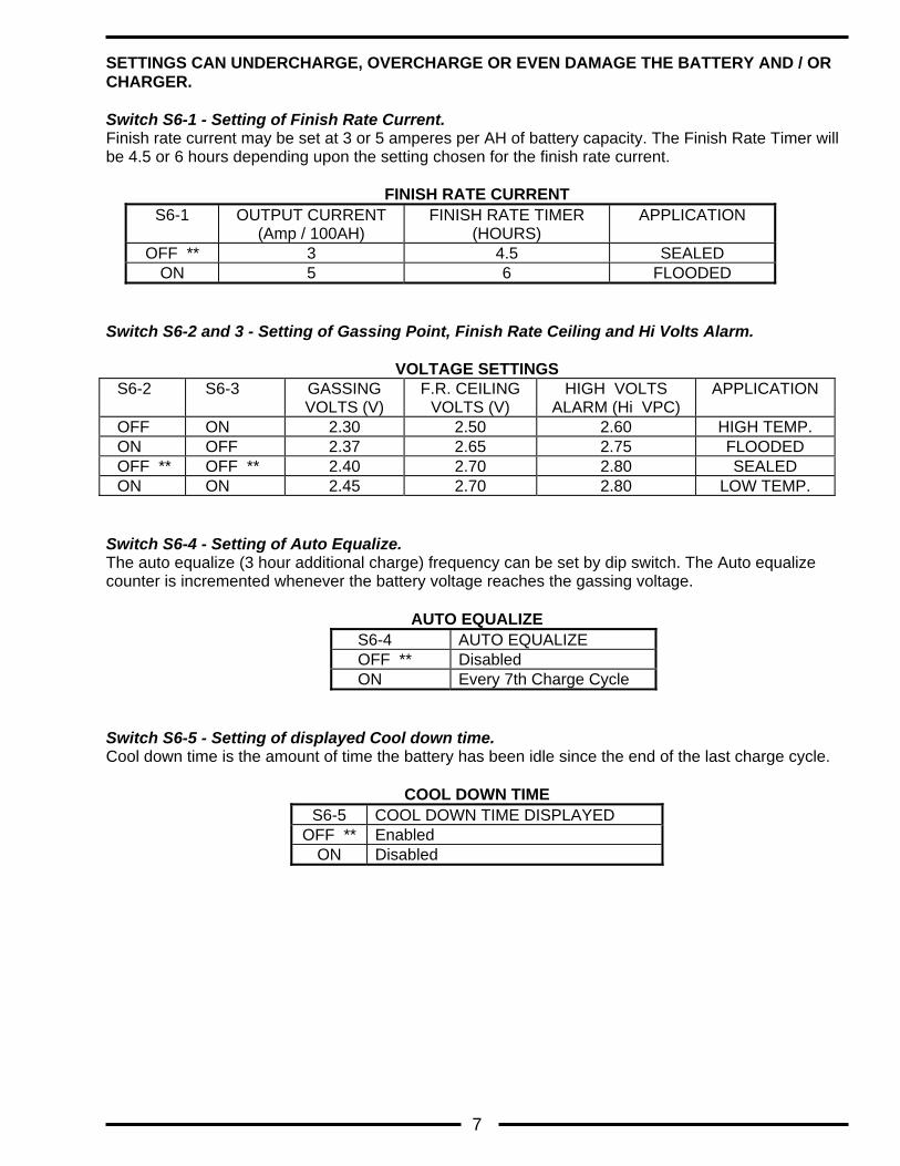
Switch S6-1 - Setting of Finish Rate Current. Finish rate current may be set at 3 or 5 amperes per AH of battery capacity. The Finish Rate Timer will be 4.5 or 6 hours depending upon the setting chosen for the finish rate current.
FINISH RATE CURRENT S6-1 OUTPUT CURRENT
(Amp / 100AH) FINISH RATE TIMER
(HOURS) APPLICATION
OFF ** 3 4.5 SEALED ON 5 6 FLOODED
Switch S6-2 and 3 - Setting of Gassing Point, Finish Rate Ceiling and Hi Volts Alarm.
VOLTAGE SETTINGS S6-2 S6-3 GASSING
VOLTS (V) F.R. CEILING
VOLTS (V) HIGH VOLTS
ALARM (Hi VPC) APPLICATION
OFF ON 2.30 2.50 2.60 HIGH TEMP. ON OFF 2.37 2.65 2.75 FLOODED OFF ** OFF ** 2.40 2.70 2.80 SEALED ON ON 2.45 2.70 2.80 LOW TEMP.
Switch S6-4 - Setting of Auto Equalize. The auto equalize (3 hour additional charge) frequency can be set by dip switch. The Auto equalize counter is incremented whenever the battery voltage reaches the gassing voltage.
AUTO EQUALIZE
S6-4 AUTO EQUALIZE OFF ** Disabled ON Every 7th Charge Cycle
Switch S6-5 - Setting of displayed Cool down time. Cool down time is the amount of time the battery has been idle since the end of the last charge cycle.
COOL DOWN TIME S6-5 COOL DOWN TIME DISPLAYED
OFF ** Enabled ON Disabled
8
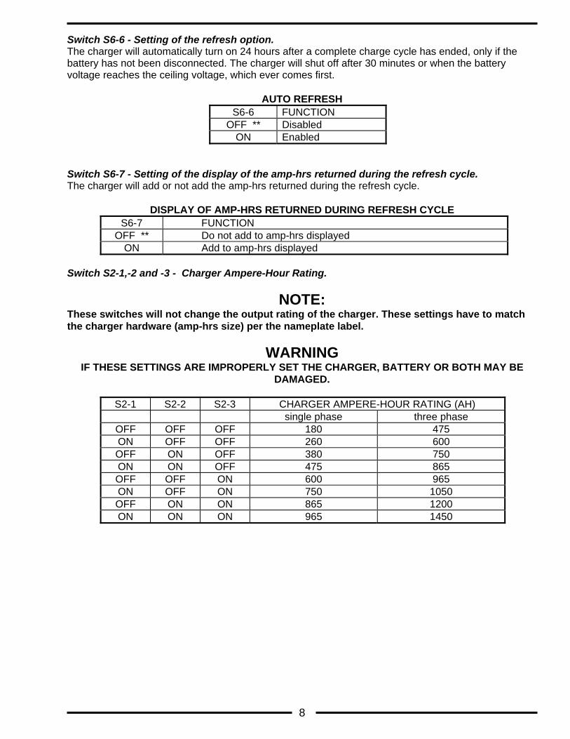
Switch S6-6 - Setting of the refresh option. The charger will automatically turn on 24 hours after a complete charge cycle has ended, only if the battery has not been disconnected. The charger will shut off after 30 minutes or when the battery voltage reaches the ceiling voltage, which ever comes first.
AUTO REFRESH S6-6 FUNCTION
OFF ** Disabled ON Enabled
Switch S6-7 - Setting of the display of the amp-hrs returned during the refresh cycle. The charger will add or not add the amp-hrs returned during the refresh cycle.
DISPLAY OF AMP-HRS RETURNED DURING REFRESH CYCLE S6-7 FUNCTION
OFF ** Do not add to amp-hrs displayed ON Add to amp-hrs displayed
Switch S2-1,-2 and -3 - Charger Ampere-Hour Rating.
NOTE: These switches will not change the output rating of the charger. These settings have to match the charger hardware (amp-hrs size) per the nameplate label.
WARNING IF THESE SETTINGS ARE IMPROPERLY SET THE CHARGER, BATTERY OR BOTH MAY BE
DAMAGED.
S2-1 S2-2 S2-3 CHARGER AMPERE-HOUR RATING (AH) single phase three phase
OFF OFF OFF 180 475 ON OFF OFF 260 600 OFF ON OFF 380 750 ON ON OFF 475 865 OFF OFF ON 600 965 ON OFF ON 750 1050 OFF ON ON 865 1200 ON ON ON 965 1450
9
OPERATING PROCEDURE Preliminary Set-Up With all power removed from the charger, verify that the DIP switches are properly set before attempting to charge a battery. Refer to the tables on pages 7-8 and to the DIP switch label inside the charger door. Once power has been applied to the charger, a "dash" will sequence across the display on the front panel. This indicates the charger is in the "IDLE MODE", awaiting a battery connection. Immediate/Delay Start The control may be programmed to delay the start of the charge from one to nine hours as well as an immediate start of the charge upon battery to charger connection. Note, all units are shipped from the factory set for immediate start (0 hour delay). If a power failure occurs, no damage will occur to the battery or the charger. If a battery is still connected when power returns, the LEGACY PLATINUM will override any delayed start setting and initialize an immediate start of the charge. Once the charge has been terminated, the delay start will function normally thereafter.
1. Remove AC power from the LEGACY PLATINUM SERIES charger.
2. Open the charger cabinet door.
3. Locate the DELAY START thumbwheel switch behind the front panel at the bottom of the control board. Adjust the DELAY START thumbwheel switch until the NUMBER INDICATOR on the switch yields the number of delay hours desired.
4. Close and secure the cabinet door.
5. Apply AC power to the LEGACY PLATINUM SERIES charger.
6. Without a battery connected the setting may be checked by pressing and holding the stop button. When a good, proper sized battery is connected to the LEGACY PLATINUM SERIES charger, the display will indicate the amount of time before the charge is initiated and the control will begin a count-down to charge.
Charging The Battery Compare the number of cells and amp-hour capacity of the battery to be charged with the charger rating found on the charger nameplate. The number of cells in the battery to be charged MUST match the nameplate data. The amp-hour ratings should also match for timely charging of the battery. Once the battery to be charged has been determined to match the charger, then connect the battery to the charger. The control will measure the average volts/cell of the connected battery.
1. If the control has verified the connection of a good battery (between 1.5 and 2.7 volts/cell), the display will show a countdown to charge initialization and the LED’s will be flashing. When the countdown reaches zero, the control will start the charging operation.
2. If the average volts/cell reading is less than 1.5 volts, the display shows “Lo U”, the charge will not begin and the red SHUTDOWN LED will be flashing. If the battery voltage “floats” above 1.5 vpc the charger will automatically begin a normal charge cycle.
3. To override the “Lo U” condition press and hold the Stop and Equalize buttons for ten seconds . The charger will begin charging. If the battery voltage does not rise above the 1.5 vpc limit within 5 minutes the charger will be locked off and the override function will not allow any additional “jump start” cycles.
10
4. When charging an overly discharged or sulfated battery the battery voltage may rise very quickly for the first few minutes and then return to the “normal” voltage. If the peak voltage reaches the gassing point and then falls more than 50 mV per cell below the gassing point the charger will shut off. The SHUTDOWN LED will be flashing and there will be no fault code displayed.
5. If the average volts/cell is greater than the High Volts Alarm, the display shows “ HI U”, the red SHUTDOWN LED will turn on. Again, the charge will not begin.
6. Once the charge begins, the display will count down from 9 to 0 then show the output charging current in amperes. The green CHARGING LED will be on. The chargers offer a three-stage charge cycle. The Green Charge LED will illuminate throughout the charge cycle.
Finish rate is split into two phases, constant voltage and constant current. The 80% Charged LED will illuminate during these phases. The constant voltage phase begins after the gassing point is reached. During the constant voltage phase, the charger voltage is regulated at the gassing point level, and the current is allowed to gradually drop. Once the current drops to the finish rate current setting (3 or 5 amps/AH, the charge phase will change from constant voltage to constant current. Changing from constant voltage to constant current is done by removing the gassing point voltage limit and allowing the voltage to rise, while at the same time setting the current limit lower, at 3 or 5 amps/AH. During this constant current stage, a ceiling voltage still remains in effect. If the battery voltage reaches this limit, the charger will come out of current limit and the finish rate current limit will begin to taper off gradually. During this phase, the charger will be shut off by dv/dt or finish rate time limit. Manual Termination Manual termination, while charging, is accomplished by pressing the STOP push-button switch located on the front panel.
CAUTION To remove a charging battery from the charger, it is important to press the STOP push-button switch first before disconnecting the battery from the charger. Failure to do this may damage the charger. When the charge has been terminated due to MANUAL TERMINATION, the red SHUTDOWN LED will be on solid until the battery is removed. The display will show “OFF”. Problem Shutdown Each of the PROBLEM SHUTDOWN termination’s are indicated by a flashing red SHUTDOWN LED and a FAULT code (page 5). After the battery is removed, the red SHUTDOWN LED will remain flashing. The fault code will remain until the battery is disconnected from the charger. Refer to page 5 , item 13, for a more complete explanation of the diagnostics. Refresh Charge When a battery remains connected to the charger for 24 hours after the charge has been completed, the control will restart another charge cycle. The charge rate of the battery will be monitored with dv/dt termination occurring typically within 30 minutes. When the charger is in this REFRESH mode the charge amps will be displayed and the CHARGING LED and the 80% CHARGE LED will be on and the CHARGE COMPLETE LED will be blinking.
11
Three Hour Equalize Button The equalize button when pushed will provide a timed three hour charge extension after dv/dt termination has been reached. When the Equalize button is depressed an “E” will appear in the left most digit of the display, and the charge complete led will flash (1/2 second on every 4 sec.). When the charger is actually in the equalize mode the “E” will be flashing. The equalize function can be disabled prior to the start of the equalize cycle by depressing the Equalize button a second time.
Display Mode Button 1. Press once to display the AMP-HRS returned this charge cycle. 2. Press twice to display the length of CHARGE this cycle. 3. Press three times to display the AVERAGE VOLTS per CELL of the battery. The display will show the above function for approximately 10 seconds and than return to display charge current or the sequencing dash.
12
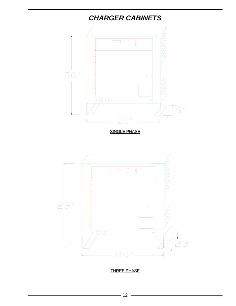
CHARGER CABINETS
SINGLE PHASE
THREE PHASE
13
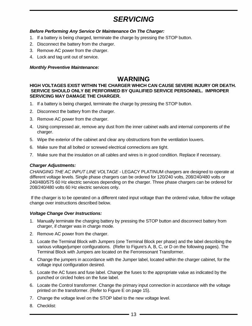
SERVICING
Before Performing Any Service Or Maintenance On The Charger: 1. If a battery is being charged, terminate the charge by pressing the STOP button. 2. Disconnect the battery from the charger. 3. Remove AC power from the charger. 4. Lock and tag unit out of service. Monthly Preventive Maintenance:
WARNING HIGH VOLTAGES EXIST WITHIN THE CHARGER WHICH CAN CAUSE SEVERE INJURY OR DEATH. SERVICE SHOULD ONLY BE PERFORMED BY QUALIFIED SERVICE PERSONNEL. IMPROPER SERVICING MAY DAMAGE THE CHARGER. 1. If a battery is being charged, terminate the charge by pressing the STOP button.
2. Disconnect the battery from the charger.
3. Remove AC power from the charger.
4. Using compressed air, remove any dust from the inner cabinet walls and internal components of the charger.
5. Wipe the exterior of the cabinet and clear any obstructions from the ventilation louvers.
6. Make sure that all bolted or screwed electrical connections are tight.
7. Make sure that the insulation on all cables and wires is in good condition. Replace if necessary. Charger Adjustments: CHANGING THE AC INPUT LINE VOLTAGE - LEGACY PLATINUM chargers are designed to operate at different voltage levels. Single phase chargers can be ordered for 120/240 volts, 208/240/480 volts or 240/480/575 60 Hz electric services depending on the charger. Three phase chargers can be ordered for 208/240/480 volts 60 Hz electric services only. If the charger is to be operated on a different rated input voltage than the ordered value, follow the voltage change over instructions described below. Voltage Change Over Instructions: 1. Manually terminate the charging battery by pressing the STOP button and disconnect battery from
charger, if charger was in charge mode.
2. Remove AC power from the charger.
3. Locate the Terminal Block with Jumpers (one Terminal Block per phase) and the label describing the various voltage/jumper configurations. (Refer to Figure's A, B, C, or D on the following pages). The Terminal Block with Jumpers are located on the Ferroresonant Transformer.
4. Change the jumpers in accordance with the Jumper label, located within the charger cabinet, for the voltage input configuration desired.
5. Locate the AC fuses and fuse label. Change the fuses to the appropriate value as indicated by the punched or circled holes on the fuse label.
6. Locate the Control transformer. Change the primary input connection in accordance with the voltage printed on the transformer. (Refer to Figure E on page 15).
7. Change the voltage level on the STOP label to the new voltage level.
8. Checklist:
14
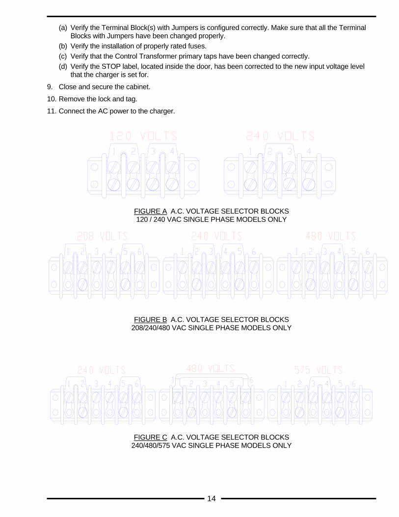
(a) Verify the Terminal Block(s) with Jumpers is configured correctly. Make sure that all the Terminal Blocks with Jumpers have been changed properly.
(b) Verify the installation of properly rated fuses. (c) Verify that the Control Transformer primary taps have been changed correctly. (d) Verify the STOP label, located inside the door, has been corrected to the new input voltage level
that the charger is set for.
9. Close and secure the cabinet.
10. Remove the lock and tag.
11. Connect the AC power to the charger.
FIGURE A A.C. VOLTAGE SELECTOR BLOCKS 120 / 240 VAC SINGLE PHASE MODELS ONLY
FIGURE B A.C. VOLTAGE SELECTOR BLOCKS 208/240/480 VAC SINGLE PHASE MODELS ONLY
FIGURE C A.C. VOLTAGE SELECTOR BLOCKS 240/480/575 VAC SINGLE PHASE MODELS ONLY
15
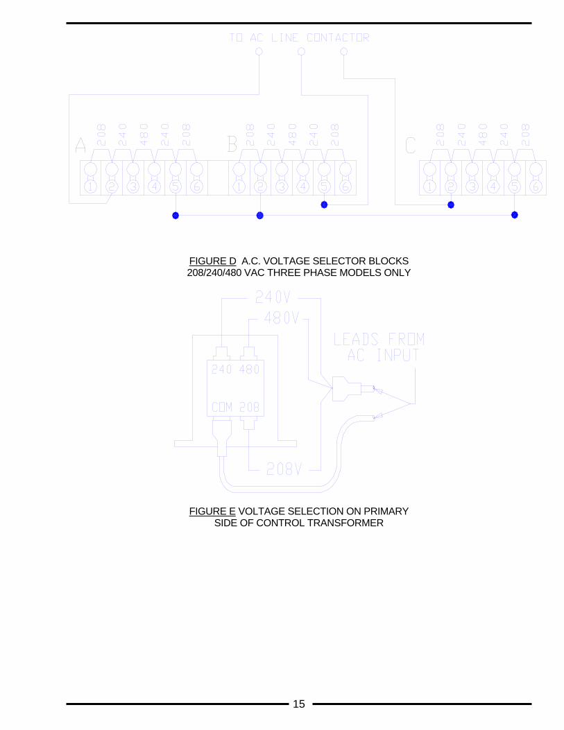
FIGURE D A.C. VOLTAGE SELECTOR BLOCKS 208/240/480 VAC THREE PHASE MODELS ONLY
FIGURE E VOLTAGE SELECTION ON PRIMARY SIDE OF CONTROL TRANSFORMER

16
START & FINISH RATE ADJUSTMENT
WARNING HIGH VOLTAGES EXIST WITHIN THE CHARGER WHICH CAN CAUSE SEVERE INJURY OR DEATH. SERVICE SHOULD ONLY BE PERFORMED BY QUALIFIED SERVICE PERSONNEL. IMPROPER SERVICING MAY DAMAGE THE CHARGER. The charge profile is determined by the control board settings. The capacitor taps are set for optimum performance at the factory. Do not attempt to adjust the capacitor taps without written factory instructions and approval.
17
TROUBLESHOOTING GUIDE
NOTE: REFER TO THE SCHEMATICS IN SECTION 10 TO LOCATE SPECIFIED COMPONENTS AND
CONNECTIONS
Symptom - Power Is Applied But The Display Is Not On: AC POWER CONNECTION - Make sure the AC input line, located at the AC FUSE BLOCK, is connected to the AC power outlet. Measure the voltage and verify that AC power is at the charger. CONTROL TRANSFORMER - Locate the Control Transformer. Measure the AC input voltage at the Control Transformer primary. If there is no voltage measured, repair open circuit.
Measure the Control Transformer secondary voltage across terminals 5 and 7. The AC voltage should be approximately (18 to 20) volts rms. If no voltage is measured, then the Control Transformer is defective and should be replaced. If the measured voltage is extremely high or low, verify that the AC line input is connected to the proper terminals of the Control Transformer. (Refer to page 13 Charger Adjustments: CHANGING THE AC INPUT LINE VOLTAGE.)
MAIN, CELL SELECT CONNECTIONS - Locate the Main board and Cell Select board on the front panel. Verify the proper connection and polarity of the board and cables. MAIN BOARD - If there is the appropriate voltage level across the Control Transformer disconnect AC power then reapply AC power. This action will reset the Micro controller. If the display is still not on, replace the main and/or cell select board. Symptom - Power Is Applied. Display Is In Idle Mode But Charger Will Not Start Or Charge Starts But Is Terminated Immediately: PROPER BATTERY - Verify that the number of cells of the battery to be charged matches the charger. Also, check the Fault codes on page 5. BATTERY CONDITION - Measure the total battery voltage. Divide the voltage value measured by the number of battery cells. This will yield an average volts per cell value. If the average volts per cell value is less than 1.5 volts or greater than 2.7 volts, then the battery is bad and should not be used. AC & DC FUSES - Disconnect the battery and AC input power from the charger. Verify that the fuses are not open. Replace any defective fuses and check the following:
Make sure that the battery to charger connector cables connect the battery to the charger with the proper polarity.
Verify that the Terminal Block with Jumpers is correctly configured for the AC input voltage currently being used. If the jumpers are not correctly configured, then go to page 13 Charger Adjustments: CHANGING THE AC INPUT LINE VOLTAGE.
Verify that AC power and battery has been disconnected from the charger. Locate the rectifier diodes on the heat sink. Remove the connecting wires from the diodes. Test the diodes and replace if faulty.
Make sure all connections are tight.
18
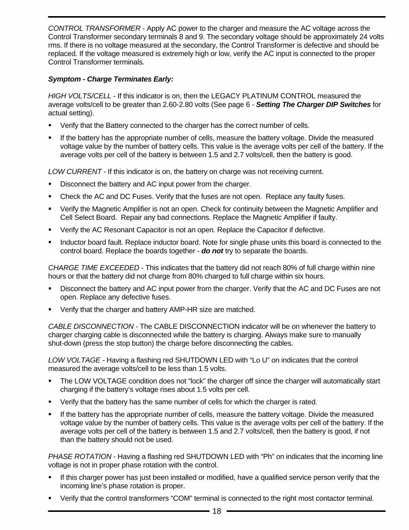
CONTROL TRANSFORMER - Apply AC power to the charger and measure the AC voltage across the Control Transformer secondary terminals 8 and 9. The secondary voltage should be approximately 24 volts rms. If there is no voltage measured at the secondary, the Control Transformer is defective and should be replaced. If the voltage measured is extremely high or low, verify the AC input is connected to the proper Control Transformer terminals. Symptom - Charge Terminates Early: HIGH VOLTS/CELL - If this indicator is on, then the LEGACY PLATINUM CONTROL measured the average volts/cell to be greater than 2.60-2.80 volts (See page 6 - Setting The Charger DIP Switches for actual setting).
Verify that the Battery connected to the charger has the correct number of cells.
If the battery has the appropriate number of cells, measure the battery voltage. Divide the measured voltage value by the number of battery cells. This value is the average volts per cell of the battery. If the average volts per cell of the battery is between 1.5 and 2.7 volts/cell, then the battery is good.
LOW CURRENT - If this indicator is on, the battery on charge was not receiving current.
Disconnect the battery and AC input power from the charger.
Check the AC and DC Fuses. Verify that the fuses are not open. Replace any faulty fuses.
Verify the Magnetic Amplifier is not an open. Check for continuity between the Magnetic Amplifier and Cell Select Board. Repair any bad connections. Replace the Magnetic Amplifier if faulty.
Verify the AC Resonant Capacitor is not an open. Replace the Capacitor if defective.
Inductor board fault. Replace inductor board. Note for single phase units this board is connected to the control board. Replace the boards together - do not try to separate the boards.
CHARGE TIME EXCEEDED - This indicates that the battery did not reach 80% of full charge within nine hours or that the battery did not charge from 80% charged to full charge within six hours.
Disconnect the battery and AC input power from the charger. Verify that the AC and DC Fuses are not open. Replace any defective fuses.
Verify that the charger and battery AMP-HR size are matched. CABLE DISCONNECTION - The CABLE DISCONNECTION indicator will be on whenever the battery to charger charging cable is disconnected while the battery is charging. Always make sure to manually shut-down (press the stop button) the charge before disconnecting the cables. LOW VOLTAGE - Having a flashing red SHUTDOWN LED with “Lo U” on indicates that the control measured the average volts/cell to be less than 1.5 volts.
The LOW VOLTAGE condition does not “lock” the charger off since the charger will automatically start charging if the battery’s voltage rises about 1.5 volts per cell.
Verify that the battery has the same number of cells for which the charger is rated.
If the battery has the appropriate number of cells, measure the battery voltage. Divide the measured voltage value by the number of battery cells. This value is the average volts per cell of the battery. If the average volts per cell of the battery is between 1.5 and 2.7 volts/cell, then the battery is good, if not than the battery should not be used.
PHASE ROTATION - Having a flashing red SHUTDOWN LED with “Ph” on indicates that the incoming line voltage is not in proper phase rotation with the control.
If this charger power has just been installed or modified, have a qualified service person verify that the incoming line’s phase rotation is proper.
Verify that the control transformers “COM” terminal is connected to the right most contactor terminal.

19
Verify that the wires from the AC FUSES go in order from A - B- C to the contactor terminals from left to right respectively.
20
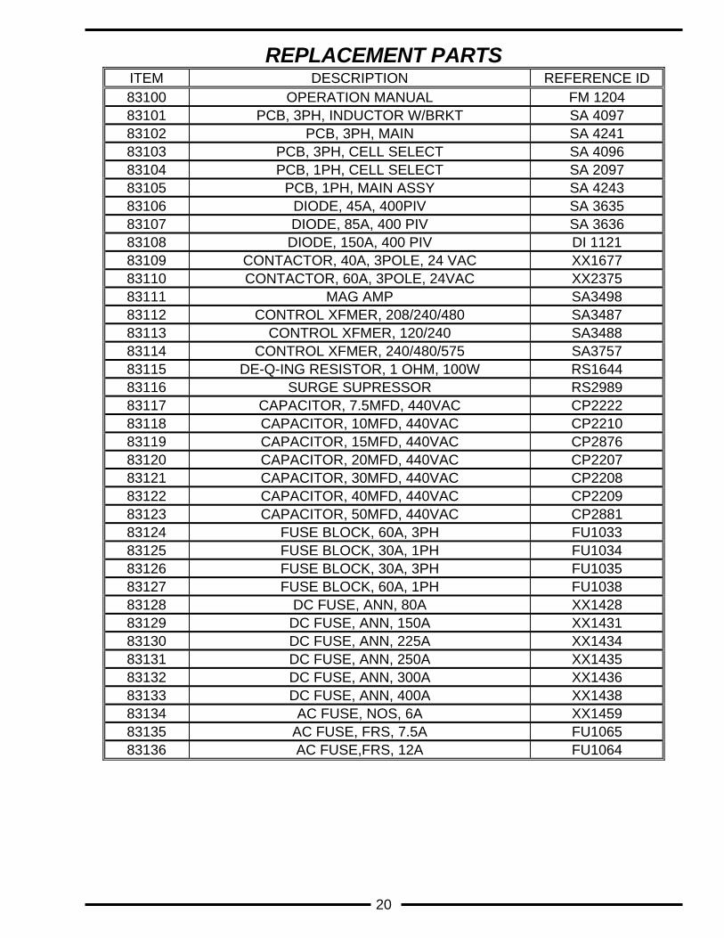
REPLACEMENT PARTS ITEM DESCRIPTION REFERENCE ID 83100 OPERATION MANUAL FM 1204 83101 PCB, 3PH, INDUCTOR W/BRKT SA 4097 83102 PCB, 3PH, MAIN SA 4241 83103 PCB, 3PH, CELL SELECT SA 4096 83104 PCB, 1PH, CELL SELECT SA 2097 83105 PCB, 1PH, MAIN ASSY SA 4243 83106 DIODE, 45A, 400PIV SA 3635 83107 DIODE, 85A, 400 PIV SA 3636 83108 DIODE, 150A, 400 PIV DI 1121 83109 CONTACTOR, 40A, 3POLE, 24 VAC XX1677 83110 CONTACTOR, 60A, 3POLE, 24VAC XX2375 83111 MAG AMP SA3498 83112 CONTROL XFMER, 208/240/480 SA3487 83113 CONTROL XFMER, 120/240 SA3488 83114 CONTROL XFMER, 240/480/575 SA3757 83115 DE-Q-ING RESISTOR, 1 OHM, 100W RS1644 83116 SURGE SUPRESSOR RS2989 83117 CAPACITOR, 7.5MFD, 440VAC CP2222 83118 CAPACITOR, 10MFD, 440VAC CP2210 83119 CAPACITOR, 15MFD, 440VAC CP2876 83120 CAPACITOR, 20MFD, 440VAC CP2207 83121 CAPACITOR, 30MFD, 440VAC CP2208 83122 CAPACITOR, 40MFD, 440VAC CP2209 83123 CAPACITOR, 50MFD, 440VAC CP2881 83124 FUSE BLOCK, 60A, 3PH FU1033 83125 FUSE BLOCK, 30A, 1PH FU1034 83126 FUSE BLOCK, 30A, 3PH FU1035 83127 FUSE BLOCK, 60A, 1PH FU1038 83128 DC FUSE, ANN, 80A XX1428 83129 DC FUSE, ANN, 150A XX1431 83130 DC FUSE, ANN, 225A XX1434 83131 DC FUSE, ANN, 250A XX1435 83132 DC FUSE, ANN, 300A XX1436 83133 DC FUSE, ANN, 400A XX1438 83134 AC FUSE, NOS, 6A XX1459 83135 AC FUSE, FRS, 7.5A FU1065 83136 AC FUSE,FRS, 12A FU1064
21
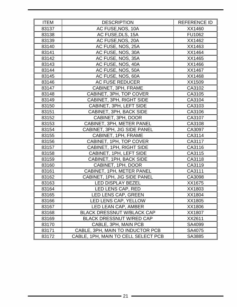
ITEM DESCRIPTION REFERENCE ID 83137 AC FUSE,NOS, 10A XX1460 83138 AC FUSE,DLS, 15A FU1062 83139 AC FUSE,NOS, 20A XX1462 83140 AC FUSE, NOS, 25A XX1463 83141 AC FUSE, NOS, 30A XX1464 83142 AC FUSE, NOS, 35A XX1465 83143 AC FUSE, NOS, 40A XX1466 83144 AC FUSE, NOS, 50A XX1467 83145 AC FUSE, NOS, 60A XX1468 83146 AC FUSE REDUCER XX1509 83147 CABINET, 3PH, FRAME CA3102 83148 CABINET, 3PH, TOP COVER CA3105 83149 CABINET, 3PH, RIGHT SIDE CA3104 83150 CABINET, 3PH, LEFT SIDE CA3103 83151 CABINET, 3PH, BACK SIDE CA3106 83152 CABINET, 3PH, DOOR CA3107 83153 CABINET, 3PH, METER PANEL CA3108 83154 CABINET, 3PH, JIG SIDE PANEL CA3097 83155 CABINET, 1PH, FRAME CA3114 83156 CABINET, 1PH, TOP COVER CA3117 83157 CABINET, 1PH, RIGHT SIDE CA3116 83158 CABINET, 1PH, LEFT SIDE CA3115 83159 CABINET, 1PH, BACK SIDE CA3118 83160 CABINET, 1PH, DOOR CA3119 83161 CABINET, 1PH, METER PANEL CA3111 83162 CABINET, 1PH, JIG SIDE PANEL CA3098 83163 LED DISPLAY BEZEL XX1675 83164 LED LENS CAP, RED XX1803 83165 LED LENS CAP, GREEN XX1804 83166 LED LENS CAP, YELLOW XX1805 83167 LED LEAN CAP, AMBER XX1806 83168 BLACK DRESSNUT W/BLACK CAP XX1807 83169 BLACK DRESSNUT W/RED CAP XX2611 83170 CABLE, 3PH, MAIN PCB SA4099 83171 CABLE, 3PH, MAIN TO INDUCTOR PCB SA4075 83172 CABLE, 1PH, MAIN TO CELL SELECT PCB SA3885
22
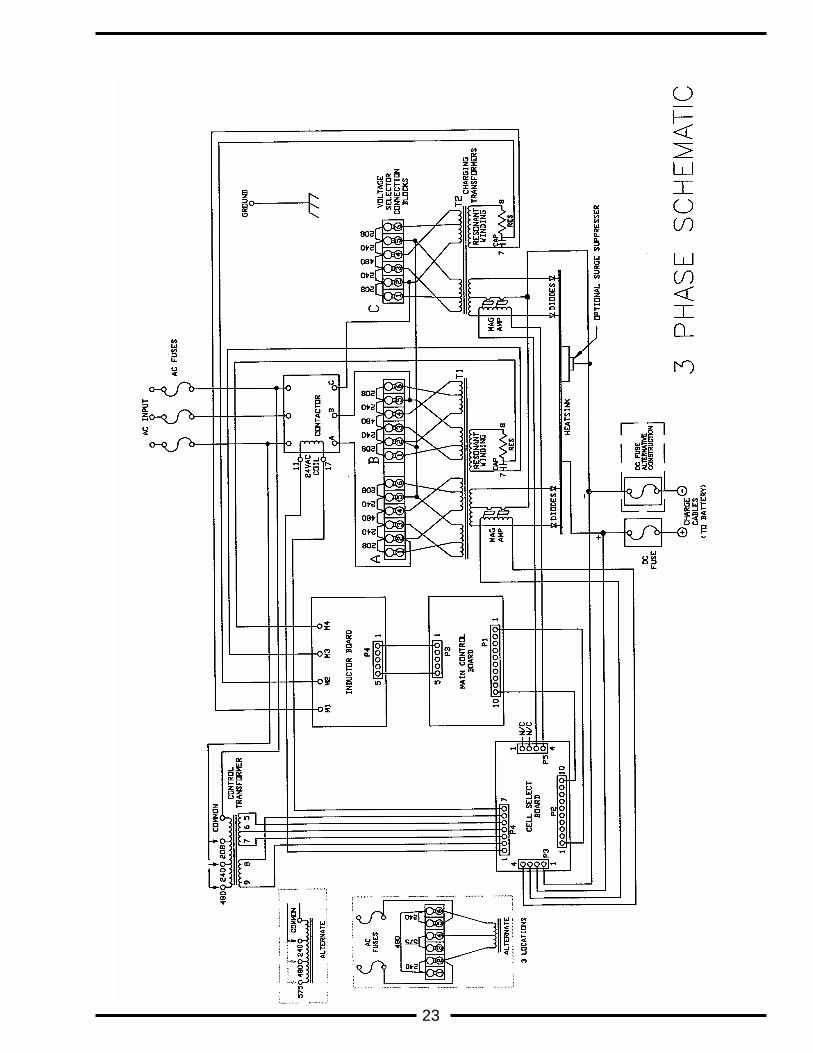
23
24
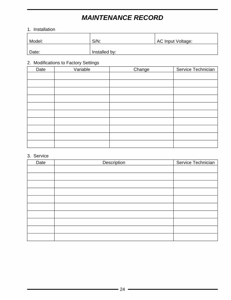
MAINTENANCE RECORD
1. Installation Model:
S/N:
AC Input Voltage:
Date:
Installed by:
2. Modifications to Factory Settings
Date Variable Change Service Technician
3. Service
Date Description Service Technician