le/esse4360 - payload design - york university · le/esse4360 - payload design ... goal is to...
TRANSCRIPT

LE/ESSE4360 - Payload Design
3.3 Optical Payloads
Dr. Jinjun Shan, Professor of Space Engineering
Department of Earth and Space Science and Engineering Room 255, Petrie Science and Engineering Building
Tel: 416-736 2100 ext. 33854 Email: [email protected]
Homepage: http://www.yorku.ca/jjshan
Earth, Moon, Mars, and Beyond

Optical Payloads 2Prof. Jinjun Shan
Goal
n Give necessary optics background to deal a space mission, which includes an optical payload

Optical Payloads 3Prof. Jinjun Shan
PART I

Optical Payloads 4Prof. Jinjun Shan
Optical Windows of Earth
SMAD
Optical Payloads 5Prof. Jinjun Shan
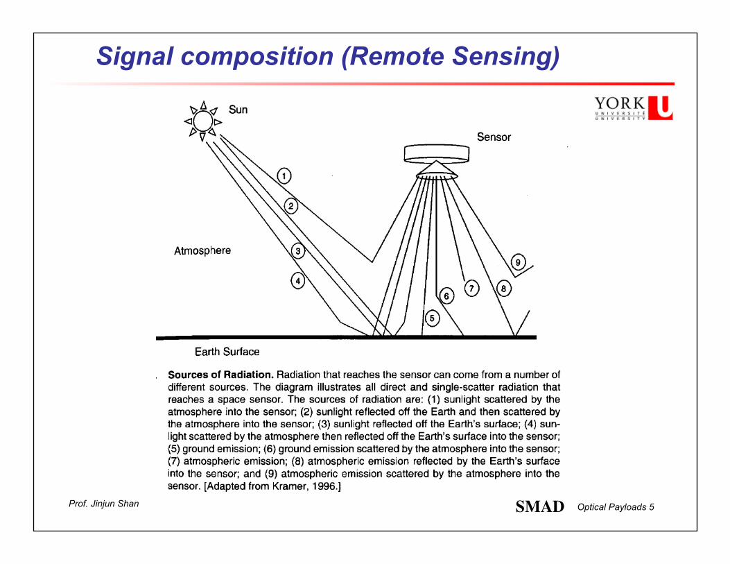
Signal composition (Remote Sensing)
SMAD

Optical Payloads 6Prof. Jinjun Shan
Typical Reflectance for Terrestrial Surfaces
n How many sensor bands are required to identify all four surfaces?

Optical Payloads 7Prof. Jinjun Shan
Two-band Sensor Solution
n Two spectral intervals are sufficient for this classification requirement.
n Obviously, would be also prudent to identify water, snow, ice, forest...
SMAD
Optical Payloads 8Prof. Jinjun Shan
Basic Telescope Optics
n Systems for gathering or transmitting optical and RF signals are identical in theory. Hardware is different.
n Optical systems divided into two classifications:
n Telescope?

Optical Payloads 9Prof. Jinjun Shan
Reflection-Mirrors

Optical Payloads 10Prof. Jinjun Shan
Transmission-Refraction
n Recall Snell’s law n Snell’s law is the
simple formula used to calculate the refraction of light when travelling between two media of differing refractive index.
§ Dispersion if index of refraction is wavelength dependent n(λ)
§ Refractive devices not popular in space imaging, since we need different lenses for UV, visual and IR.

Optical Payloads 11Prof. Jinjun Shan
Diffraction
n Light travels in straight lines through uniform air, however it begins to disperse or "diffract" when goes through a small hole. This effect is normally negligible, but increases for very small apertures.

Optical Payloads 12Prof. Jinjun Shan
Angular Resolution n Angular resolution describes the resolving power of a telescope. n Resolving power is the ability of the optical components of a telescope to
clearly separate, or resolve, two star points (i.e., two Airy discs). The term resolution is the minimum distance between distinguishable objects in an image.
n The resolving power of a lens is ultimately limited by diffraction.
n An empirical diffraction limit is given by the Rayleigh criterion θ = 1.22 λ / D
where θ is the angular distance from the center of the image to the first dark ring, λ is the wavelength of light, and D is the diameter of the lens.
n The factor 1.22 is used to approximate the ability of the human eye to
distinguish two separate point sources depending on the overlap of their Airy discs. Modern telescopes with video sensors may be slightly better than the human eye in their ability to discern overlap of Airy discs.
Optical Payloads 13Prof. Jinjun Shan
Diffraction Limited
n Goal is to design optical system to be diffraction limited at the wavelength of interest.
n The ability to produce optical images with angular separations as small as the instrument's theoretical limit. A telescope with this capability is said to be diffraction limited.
n Diffraction effects are the main contributors to this limit.
n What is resolution of human eye? n Optical telescopes on the Earth at ground level?
n Radiotelescopes? n Space-based telescopes?
n Compare hubble space telescope with Southern African Large Telescope (SALT).
n Can the Hubble Space Telescope see the Apollo craft on the moon?

Optical Payloads 14Prof. Jinjun Shan
Focal Length I
n Parallel rays incident on an optic converge or diverge from a focal point whose distance from the center of the optic is known as the focal length, f
n Focal length is the primary factor in size of required optical configuration and it determines overall instrument size.
n The focal point F and focal length f of a positive (convex) lens, a negative (concave) lens, a concave mirror, and a convex mirror.
n What is the focal length of human eye?
Optical Payloads 15Prof. Jinjun Shan
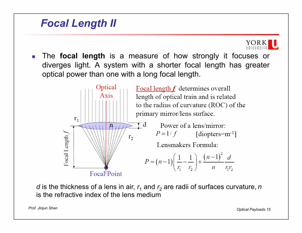
Focal Length II
n The focal length is a measure of how strongly it focuses or diverges light. A system with a shorter focal length has greater optical power than one with a long focal length.
d is the thickness of a lens in air, r1 and r2 are radii of surfaces curvature, n is the refractive index of the lens medium

Optical Payloads 16Prof. Jinjun Shan
Positive and negative lens
d is the thickness of a lens in air, R1 and R2 are radii of surfaces curvature, n is the refractive index of the lens medium

Optical Payloads 17Prof. Jinjun Shan
Field-Of-View (FOV)
n Determines the scope of the image. Defined by angle on the sky/ground we can see in one single image.
n Angular diameter of FOV:
n What is the FOV of human eye?
n What is the FOV of a rabbit?
Optical Payloads 18Prof. Jinjun Shan
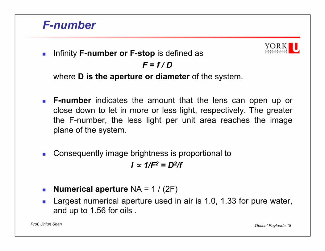
F-number
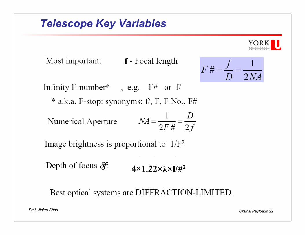
n Infinity F-number or F-stop is defined as F = f / D where D is the aperture or diameter of the system.
n F-number indicates the amount that the lens can open up or
close down to let in more or less light, respectively. The greater the F-number, the less light per unit area reaches the image plane of the system.
n Consequently image brightness is proportional to
I ∝ 1/F2 = D2/f
n Numerical aperture NA = 1 / (2F) n Largest numerical aperture used in air is 1.0, 1.33 for pure water,
and up to 1.56 for oils .
Optical Payloads 19Prof. Jinjun Shan
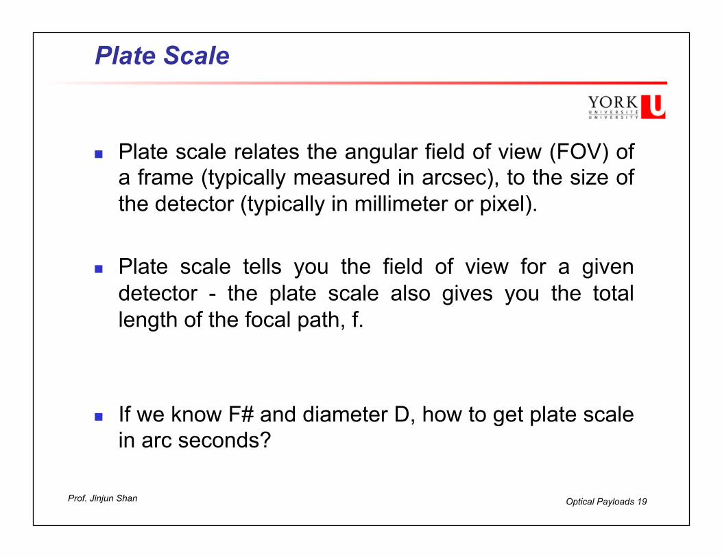
Plate Scale
n Plate scale relates the angular field of view (FOV) of a frame (typically measured in arcsec), to the size of the detector (typically in millimeter or pixel).
n Plate scale tells you the field of view for a given detector - the plate scale also gives you the total length of the focal path, f.
n If we know F# and diameter D, how to get plate scale in arc seconds?
Optical Payloads 20Prof. Jinjun Shan
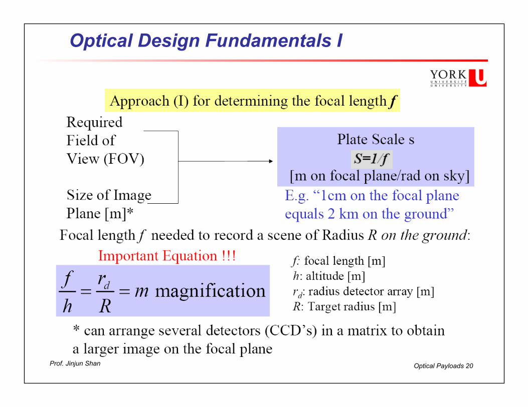
Optical Design Fundamentals I
Optical Payloads 21Prof. Jinjun Shan
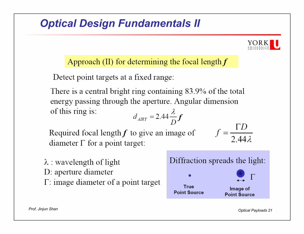
Optical Design Fundamentals II
f
Optical Payloads 22Prof. Jinjun Shan
Telescope Key Variables
4×1.22×λ×F#2

Optical Payloads 23Prof. Jinjun Shan
Depth of Focus and Depth of Field

Optical Payloads 24Prof. Jinjun Shan
Depth of Focus - Telecscope
Depth of Focus
F# in millimeters in micronsf/1 .003172 mm 3.172 µm
f/1.4 .006216 mm 6.216 µm
f/2 .012688 mm 12.688 µm
f/2.8 .024864 mm 24.864 µm
f/4 .050752 mm 50.752 µm
f/5.6 .099467 mm 99.467 µm
f/8 .203008 mm 203.008 µm
f/11 .383812 mm 383.812 µm
f/16 .812032 mm 812.032 µm

Optical Payloads 25Prof. Jinjun Shan
Space Based Imaging

Optical Payloads 26Prof. Jinjun Shan
Ground Resolution
Optical Payloads 27Prof. Jinjun Shan
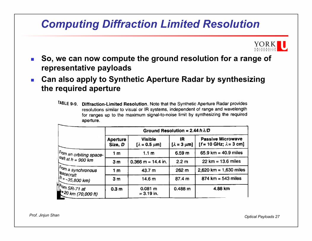
Computing Diffraction Limited Resolution
n So, we can now compute the ground resolution for a range of representative payloads
n Can also apply to Synthetic Aperture Radar by synthesizing the required aperture
Optical Payloads 28Prof. Jinjun Shan
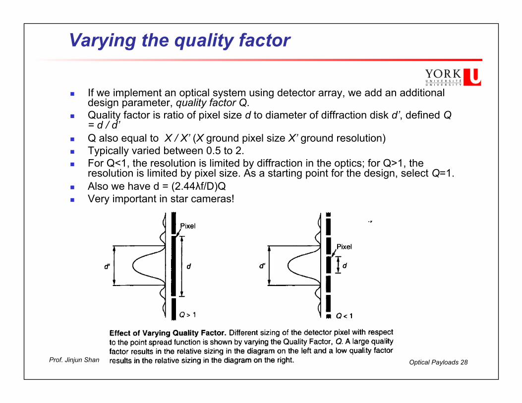
Varying the quality factor
n If we implement an optical system using detector array, we add an additional design parameter, quality factor Q.
n Quality factor is ratio of pixel size d to diameter of diffraction disk d’, defined Q = d / d’
n Q also equal to X / X’ (X ground pixel size X’ ground resolution) n Typically varied between 0.5 to 2. n For Q<1, the resolution is limited by diffraction in the optics; for Q>1, the
resolution is limited by pixel size. As a starting point for the design, select Q=1. n Also we have d = (2.44λf/D)Q n Very important in star cameras!
Optical Payloads 29Prof. Jinjun Shan
Optical Aberrations I
n Chromic Aberration: Dispersion of light due to variation of refractive index with wavelength or frequency
n Modern lenses are dispersion adjusted for several wavelengths n Spherical Aberration: Dispersion where light from element edges is
focussed too near the element. Solution is to use parabolic lens elements. Most telescopes are designed to eliminate this aberration.
n Coma: Dispersion of off-axis portions of the image (coma of a comet). Coma of a single lens can be minimized (in some cases eliminated) by choosing the curvature of the lens surfaces to match the application
n Astigmatism: An aberration where the image is focused differently in the horizontal plane than from the vertical. Very common in humans! It is generally associated with poorly made optics or collimation errors.
n Distortion: The alteration of the original shape (or other characteristic) of an object, image, sound, waveform or other form of information or representation. These distortions are minimized by using symmetric doublets
n Curvature of Field: Caused by the light rays not all coming to a sharp focus in the same plane. The center of the field may be sharp and in focus but the edges are out of focus and vice versa.

Optical Payloads 30Prof. Jinjun Shan
PART II

Optical Payloads 31Prof. Jinjun Shan
Basic Optical Configurations

Optical Payloads 32Prof. Jinjun Shan
Optical Design Trade-offs
n Triplet design allows correction for all types of distortion but requires more optical elements
n Also, has largest sensitivity to optic element placement and tilt n Even in perfectly focused image a point of light or star will appear
as a central bright spot surrounded by concentric rings of light

Optical Payloads 33Prof. Jinjun Shan
Typical Application: MOMS 2P

Optical Payloads 34Prof. Jinjun Shan
Primary Aperture Types
Examples: Hubble Space Telescope
Examples: James Webb Space Telescope
Examples: Very Large Telescope
Optical Payloads 35Prof. Jinjun Shan
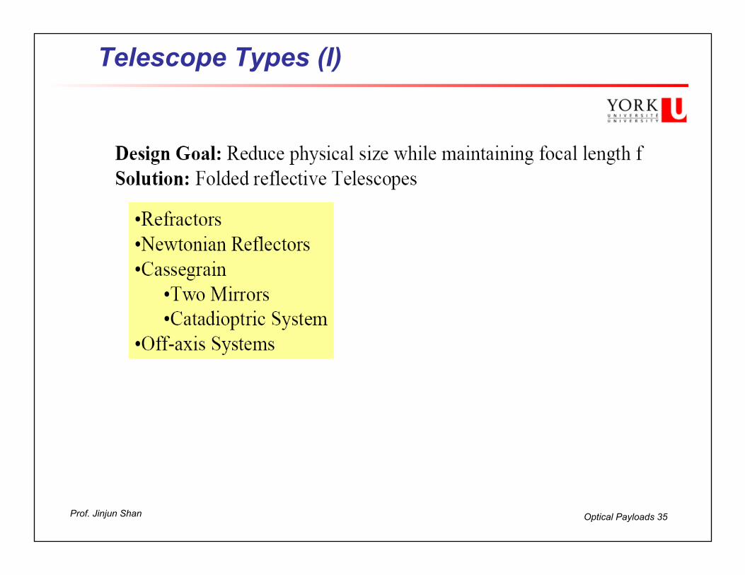
Telescope Types (I)

Optical Payloads 36Prof. Jinjun Shan
Telescope Type (II)
n A refractor telescope is a type of optical telescope that refracts or bends light at each end using lenses. This refraction causes parallel light rays to converge at a focal point; while those which were not parallel converge upon a focal plane.
n Single Mirror (Newtonian): A small diagonal mirror is inserted in the focusing beam. A more accessible focused Spot, but produces a central obscuration in the aperture and off-axis coma.

Optical Payloads 37Prof. Jinjun Shan
Telescope Types (III) – Cassegrain (Two Mirrors)
The Ritchey-Chrétien is free of coma and spherical aberration at a flat focal plane, making it well suited for wide field and photographic observations. Almost every professional reflector telescope in the world is of the Ritchey-Chrétien design.
Optical Payloads 38Prof. Jinjun Shan
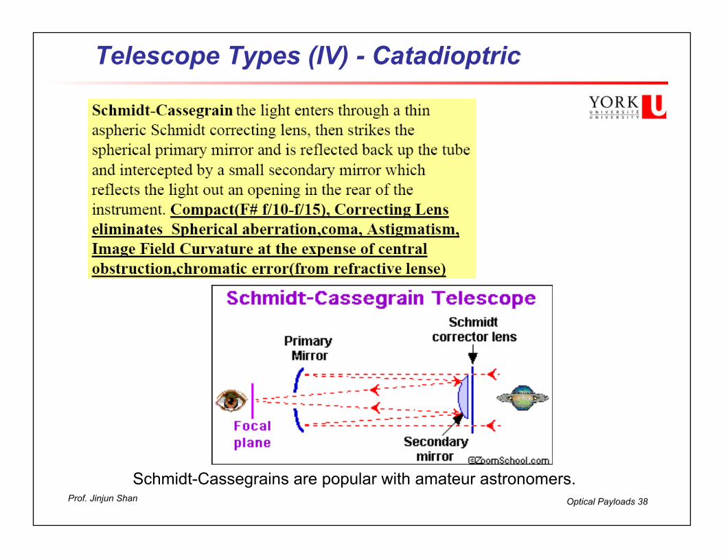
Telescope Types (IV) - Catadioptric
Schmidt-Cassegrains are popular with amateur astronomers.
Optical Payloads 39Prof. Jinjun Shan
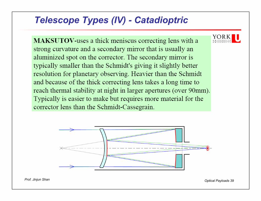
Telescope Types (IV) - Catadioptric

Optical Payloads 40Prof. Jinjun Shan
Interferometer Types

Optical Payloads 41Prof. Jinjun Shan
Technological Trends
n Lightweight (Low-Area-Density) Optics -15kg/m2
n Deployable Optics n Adaptive and Active Optics n Membrane Mirrors and Inflatables n Ultra-Large Arrays (CCD Mosaics) n Distributed Optical Arrays n Space Based Astronomy n White light interferometry

Optical Payloads 42Prof. Jinjun Shan
PART III - Detectors

Optical Payloads 43Prof. Jinjun Shan
What is Detector?

Optical Payloads 44Prof. Jinjun Shan
Classification of Optical Detectors
n Photo tube and photo multiplier tubes (110-1100 nm) are the examples of the photo emission type which has sensitivity in the region from ultra violet to visible light. n Photodiode, phototransistor, photo conductive detectors and linear array sensors are examples of optical excitation types, which have sensitivity in the infrared region. n Thermocouple bolometers and pyroelectric bolometers are examples of the thermal effect type, which has sensitivity from near infrared to far infrared regions. They must be cooled to liquid helium temperatures to avoid emission from the instrument itself.

Optical Payloads 45Prof. Jinjun Shan
Photo Tubes
n A phototube is a type of gas-filled or vacuum tube that is sensitive to light. These devices operate according to the photoelectric effect: incoming photons strike a photocathode, generating electrons, which are attracted toward the anode. Thus current flow is dependent on the frequency and intensity of incoming light. Unlike photomultiplier tubes, no amplification takes place, so the 'on' current is typically on the order of microamps.
n One major application of the phototube was the reading of optical sound tracks for projected films. They were used in a variety of light-sensing applications until they were superseded by photoresistors and photodiodes.

Optical Payloads 46Prof. Jinjun Shan
Photomultiplier Tubes (PMTS)
n Photomultiplier Tubes (PMTS) are light detectors that are useful in low intensity applications such as fluorescence spectroscopy. Due to high internal gain, PMTs are very sensitive detectors.
n PMTs are similar to phototubes. They consist of a photocathode and a series of dynodes in an evacuated glass enclosure. Photons that strikes the photoemissive cathode emits electrons due to the photoelectric effect. Instead of collecting these few electrons (there should not be a lot, since the primarily use for PMT is for very low signal) at an anode like in the phototubes, the electrons are accelerated towards a series of additional electrodes called dynodes. These electrodes are each maintained at a more positive potential. Additional electrons are generated at each dynode. This cascading effect creates 105 to 107 electrons for each photon hitting the first cathode depending on the number of dynodes and the accelerating voltage. This amplified signal is finally collected at the anode where it can be measured.

Optical Payloads 47Prof. Jinjun Shan
Photo-conductive Detectors
n Absorbed incident photons produce “free” charge carriers in surface.
n Changes the electrical conductivity of the semiconductor. n Resistance change can be measured by applying a bias
voltage which is proportional to incident flux. n Best devices have high dark resistance and low illuminated
resistance. n PbS, PbSe, MCT (Mercury-Cadmium-Telluride) and
HgCdZnTe are suitable materials.

Optical Payloads 48Prof. Jinjun Shan
Photodiodes – Modes of operation
n Junction Photodiodes have transistor like p-n junctions that allow incident photons to release electrons.
n Can be operated in two modes n Unbiased or Photovoltaic mode
n Electron-hole pairs migrate to opposite sides of the junction generating a charge.
n No bias voltage – hence no flicker noise. n Better NEP at low sample frequencies (<100Khz). n Small linear dynamic range without additional circuitry.
n Biased or Photoconductive mode n A reverse voltage bias is applied to junction. n An incident photon flux dramatically alters the
conductance across the junction that can be measured as a current.
n Careful operation near breakdown bias voltage can give further avalanche effect to amplify signal.
n Bias current causes flicker noise – preferred for high frequency pulsed operation.
p
V
n
Photon

Optical Payloads 49Prof. Jinjun Shan
Photodiodes – frequency characteristics
n Photodiode detection mechanisms wavelength dependent.
n A long wavelength cut-off occurs because incident photons do not have enough energy to create electron-hole pairs.
n A short wavelength cut-off occurs because photons get absorbed before reaching the p-n boundary region.
n Surface reflection also contributes to non-ideal behaviour, reflecting photons instead of absorbing them
200nm 1200nm
1 Quantum Efficiency (Si-Type)
0

Optical Payloads 50Prof. Jinjun Shan
Photodiodes - Types
n Si – type: Most common covering UV, Visible and near-IR 0.8 – 2.5µm.
n GaN – type: Good UV characteristics while rejecting IR.
n InSb – type: Require liquid nitrogen cooling but offer excellent performance in 2-5µm range.
n Ge, InGaAs – types: Similar to Si but require cooling.
n HgCdZnTe – small band gap gives wide IR performance from 2 to 12µm. Require cooling.

Optical Payloads 51Prof. Jinjun Shan
Thermal - Pyroelectric Detectors
n Pyroelectric materials exhibit an electric polarisation.
n When heated pyroelectric materials change their crystalline structure and consequently also their polarisaion.
n This change induces a charge build-up like a capacitor which can be measured.
n Transient Effect – detectors only respond to pulsed or modulated radiation.
n A typical pyroelectric detector consists of a sandwich of pyroelectric material, electrodes and a blackened coating.
n They can be made extremely thin (100µm thick) improving thermal response time.
n Particularly applicable in devices where radiation is already modulated like FT-IR.
V
Black Coating Electrode
Pyroelectric Electrode

Optical Payloads 52Prof. Jinjun Shan
Thermal - Bolometers
n A bolometer has a sensing element that changes resistance with temperature. We use bolometers to detect light in the far-infrared and mm-waves.
n Platinum or semiconductors (mixed metal oxides) exhibit this property.
n Tend to have a long response time (thermal mass) larger than 10ms though there have been recent advances in technology.
n Good infrared sensitivity. n Can be employed with chopper or shutter reference.
Das Bolometer Array
Optical Payloads 53Prof. Jinjun Shan
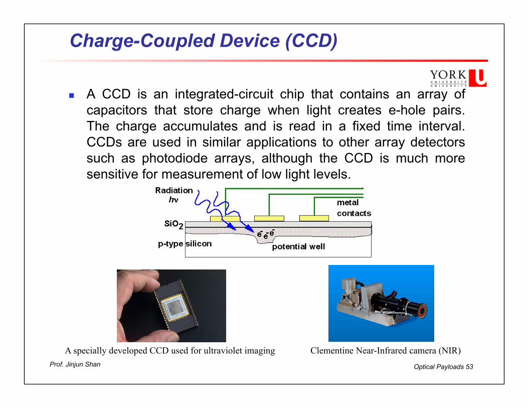
Charge-Coupled Device (CCD)
n A CCD is an integrated-circuit chip that contains an array of capacitors that store charge when light creates e-hole pairs. The charge accumulates and is read in a fixed time interval. CCDs are used in similar applications to other array detectors such as photodiode arrays, although the CCD is much more sensitive for measurement of low light levels.
A specially developed CCD used for ultraviolet imaging Clementine Near-Infrared camera (NIR)
Optical Payloads 54Prof. Jinjun Shan
Applications - CCDs
n CCDs are used in digital cameras, optical scanners and video cameras as light-sensing devices. They commonly respond to 70% of the incident light (meaning a quantum efficiency of about 70%) making them more efficient than photographic film, which captures only about 2% of the incident light.
n An interesting astronomical application is to use a CCD to make a fixed telescope behave like a tracking telescope and follow the motion of the sky. The charges in the CCD are transferred and read in a direction parallel to the motion of the sky, and at the same speed. In this way, the telescope can image a larger region of the sky than its normal field of view.
n CCDs are typically sensitive to infrared light, which allows infrared photography, night-vision devices, and zero lux (or near zero lux) video-recording/photography. Because of their sensitivity to infrared, CCDs in astronomy are usually cooled to liquid nitrogen temperatures. Cooling also reduces the array's dark current, improving the sensitivity of the CCD to low light intensities, even for ultraviolet and visible wavelengths.
Optical Payloads 55Prof. Jinjun Shan
Detector Characteristics
n Responsivity: Ratio of detector input vs. detector output R = Sout / Sin= (Sout-S0) / Sin
n Usually an energy ratio [Watts]. n Response Time: Time taken by detector to respond to a step
change in irradiance and reach (1-1/e) or ~63% of its final value [seconds].
n Linearity Range: Range over which detector will behave “linearly”. Usually quoted in terms of flux input power [W].
n Bandwidth Δf : The frequency with which we make the measurement [Hz]. Equal to 1/(2πτ) of the time τ [s] over which we make the measurement.
n Quantum Efficiency (QE): Ratio of detector electrons produced to incident photons (photon detectors). It is an accurate measurement of the device's sensitivity and is often measured over a range of different wavelengths to characterize a device's efficiency at each energy. Photographic film typically has a QE of much less than 10%, while CCDs can have a QE of well over 90% at some wavelengths.
Optical Payloads 56Prof. Jinjun Shan
Noise Equivalent Power (NEP)
n NEP is the incident photon flux that will produce a signal of a magnitude equal to the Root Mean Squared (RMS) noise output from the detector.
n Corresponds to a Signal to Noise ratio S/N = 1. n Function of detector area, spectral frequency,
modulation frequency, temperature and bandwidth. n Units are Watts, but usually quoted with normalised
bandwidth (1Hz) and units are Watts Hz-1/2.
Optical Payloads 57Prof. Jinjun Shan
Normalised Detectivity D* I
n Detectivity is the reciprocal of NEP (D = 1 / NEP) and gives a “figure of merit” to compare sensors.
n Higher Detectivity = more sensitive detector. n Normalised detectivity corrects for area and bandwidth. n As we measure for longer our signal increases linearly in
measurement time τ, but the noise increases as the square root (an effect of RMS averaging).
n Consequently, D x (1/ τ)2 = D x Δf1/2 is constant (all other things being the same).
n The same applies to the area of the detector: the signal increases linearly with detector area, and so the noise increases as the square root (or D x A1/2 is constant).

Optical Payloads 58Prof. Jinjun Shan
Normalised Detectivity D* II
n We can therefore define a new quantity “normalised detectivity” D* = D(A . Δf)1/2 = (A . Δf)1/2 / NEP where NEP is “unnormalised” or measured NEP in Watts.
n This allows a comparison of different types of detectors that is independent of detector area and bandwidth.

Optical Payloads 59Prof. Jinjun Shan
Where Does Detector Noise Come From?
n Shot Noise Energy quantised into photons that arrive at random points in time. Causes variations in number of photons sampled over a discrete period.
n Generation-recombination Noise
Where both positive and negative charge carriers are generated, spontaneous recombination of charge elements or spontaneous generation can cause variations in the signal.
Time
Sample 1 Sample 2
Optical Payloads 60Prof. Jinjun Shan
Where Does Detector Noise Come From II? n Johnson (or thermal) Noise
Thermal energy causes random motion of charge carriers inducing changes in resistance of detector or components in series.
n Flicker or 1/f noise
Excess noise at low sample frequencies in detectors that require a bias current. Mechanism is not well understood but likely a conductive effect related to local capture and release of charge carriers in surface oxide layer of detectors. Scales as 1/f n (0.8<n<1.2).
n Readout Noise
Transfer of charge between quantum well and storage register introduces measurement variations.
n Also Microphonic Noise, Electronic Noise and Temperature
Noise
Optical Payloads 61Prof. Jinjun Shan
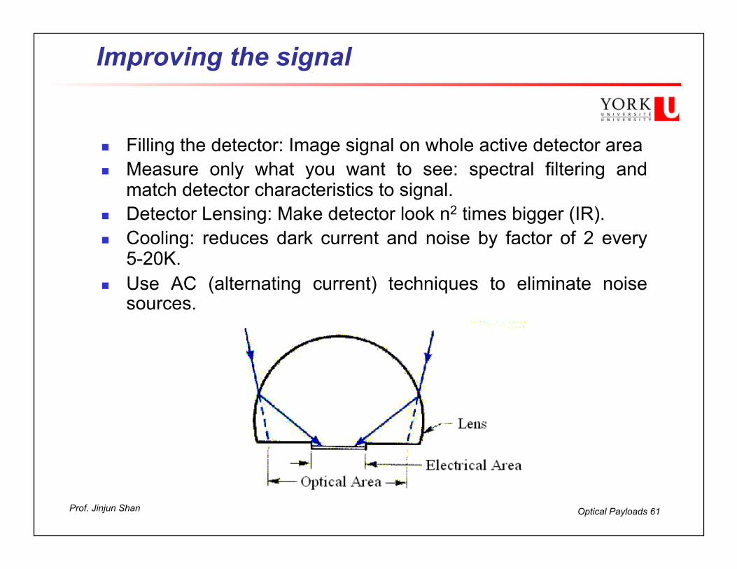
Improving the signal
n Filling the detector: Image signal on whole active detector area n Measure only what you want to see: spectral filtering and
match detector characteristics to signal. n Detector Lensing: Make detector look n2 times bigger (IR). n Cooling: reduces dark current and noise by factor of 2 every
5-20K. n Use AC (alternating current) techniques to eliminate noise
sources.

Optical Payloads 62Prof. Jinjun Shan
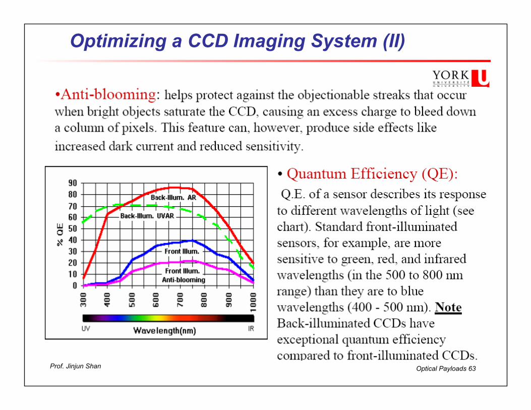
Optimizing a CCD Imaging System (I)
n Sensitivity : Rather than the total amount of signal in an image (which depends on gain in the camera's electronics), sensitivity is the signal-to-noise ratio (S/N) obtained with a given exposure time. The S/N is a measure of quality; the higher the ratio, the less gritty an image will appear.
n A very good deep sky object at least 25 S/N. n Smaller pixel(9µm)=>longer exposure time (lower sensitivity)
n a faint deep sky object may be oversampled n Larger pixel(24µm)=> greater sensitivity, undersampled for bright
source.
Optical Payloads 63Prof. Jinjun Shan
Optimizing a CCD Imaging System (II)
Optical Payloads 64Prof. Jinjun Shan
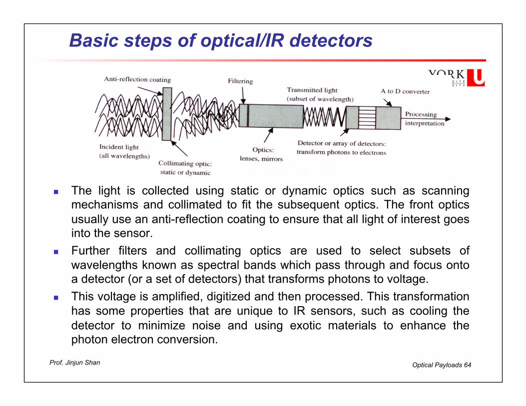
Basic steps of optical/IR detectors
n The light is collected using static or dynamic optics such as scanning mechanisms and collimated to fit the subsequent optics. The front optics usually use an anti-reflection coating to ensure that all light of interest goes into the sensor.
n Further filters and collimating optics are used to select subsets of wavelengths known as spectral bands which pass through and focus onto a detector (or a set of detectors) that transforms photons to voltage.
n This voltage is amplified, digitized and then processed. This transformation has some properties that are unique to IR sensors, such as cooling the detector to minimize noise and using exotic materials to enhance the photon electron conversion.

Optical Payloads 65Prof. Jinjun Shan
Example: Sony DSC-W50 DC
n Imaging Device: 1/ 2.5” CCD n Megapixel: 6.0 n Focal Length: 6.3 – 18.9 n Lens aperture: F/2.8-5.2 n Compensation: ±2.0EV, 1/3EV steps n Image sizes:
• 2816 x 2112 • 2048 x 1536 • 1632 x 1224 • 640 x 480
Optical Payloads 66Prof. Jinjun Shan
Observation Payload Design I
n The E&M radiation that forms the basis of remote sensing arises as a by-product of energy being transferred from one to another.
n In S/C remote sensing we are concerned with processing measurements from four primary spectral types: n Visible systems: UV (~0.3 micron) – Visual spectrum (~0.75
micron).
n Infrared systems: operate in various bands through infrared spectrum (~1-100 microns)
n Microwave radiometers: radio frequency range (20-200 GHz).
n Radar systems.

Optical Payloads 67Prof. Jinjun Shan
Observation Payload Design II
n There are a number different approaches for linking the fundamental physics of the Planck function to the practical design of remote sensing systems.
n Depending on the spectral range, we define three basic categories of Earth observation.

Optical Payloads 68Prof. Jinjun Shan
Observation Payload Design III
n Figure shows the radiance available from direct and reflected radiation sources
n According to Planck’s law, the thermal emitted radiance of the earth increases with wavelength, reflected radiance decreases with wavelength.

Optical Payloads 69Prof. Jinjun Shan
Scanning or Active Pointing
n Electro-optical imaging instruments use mechanical or electrical means to scan the scene on the ground.
n May also take advantage of spacecraft motion over the ground to observe
n Point observation instruments can be turned into scanning instruments with addition of single scan mirror
n Can also slew spacecraft (obvious trade) though operationally more complex.

Optical Payloads 70Prof. Jinjun Shan
Scanning Approach Trade-off